PhD Course in Engineering and Chemistry of Materials and Constructions
XXXIII cycle
Lightweight structures
for marine applications
:
From testing to design
Giulia Palomba
Tutor: Prof. Vincenzo Crupi
SSD: ING/IND-02 - Costruzioni e impianti navali e marini
Abstract
The main objective of the thesis was to promote a broader integration of lightweight sandwich structures in the marine industry. Amongst all possible material combinations, all-aluminium sandwich structures were selected as the focus of the study.
Weight reduction and materials sustainability are becoming of primary im-portance for marine structures, but the simultaneous application of both of these approaches is seldom considered. The literature review regarding the use of sandwich structures for marine applications, highlighted the predom-inance of the composite category, whose disposal and recycling are both dif-ficult and expensive. Therefore, a solution to both lightweight requirements and environmental issues could lie in the application of all-metal sandwich structures, and in particular of aluminium sandwich structures, which com-bine low-density and excellent mechanical properties with good recyclability and sustainability. In view of these considerations, a deeper knowledge on aluminium sandwich structures, based on experimental and analytical anal-ysis, is required to support a safe and reliable design and encourage their application.
For this purpose, aluminium sandwich structures (AHS) with honeycomb core were chosen to perform an extensive experimental investigation. Par-ticular attention was paid to two of the most critical loading condition, which may result from common in-service events: impact and fatigue loading. Low-velocity impact tests were performed on six different AHS configura-tions, both single and double-layer. The latter were introduce in order to improve the crashworthiness of sandwich structures. Double-layer panels displayed a progressive collapse sequence, depending on the core arrange-ment and on the cell size. Such observations suggested the possibility to obtain energy absorbing structures with a controlled deformation.
A theoretical evaluation was applied to investigate the mono-layer impact response and preliminary considerations on the existence of a size effect were drawn.
The fatigue analysis, which was seldom considered in previous literature on AHS, was performed applying three-point bending loading conditions. A preliminary static analysis was performed both under three and four point
bending conditions. The static tests allowed the identification of the static bending strength and the identification of cell walls buckling buckling as the main phenomena involved in AHS bending response. The influence of boundary conditions on fatigue life and on collapse modes were investigated by considering different supports spans. For one condition the S-N curve was obtained and its equation was compared to literature results. Two different collapse mechanisms were observed depending on the supports span: for larger supports span a fracture of the tensioned skin was observed, whereas lower supports span produced core shear. In both cases, failure occurred suddenly and this should be taken into consideration in real applications. An analytical model was applied to predict fatigue collapse modes and limit loads. A fatigue failure map describing the relationship between supports span, collapse modes and fatigue limit loads was obtained, in order to provide a quantitative tool for aluminium honeycomb sandwich structures design. Other innovative and efficient solution to the requirements of lightness and good mechanical performance for marine structures - with particular atten-tion to crashworthiness - could be provided by the applicaatten-tion of biomimetic principles. The idea of taking inspiration from natural strategies and struc-tures to cope with engineering problems, was introduced and developed in collaboration with Trinity College of Dublin.
Bamboo was selected as the natural structure to analyse and mimic, espe-cially for what concerns impact behaviour. Bamboo samples were subjected to impact both on the outside and on the inside surface. It was found that the impact strength is correlated to the thickness and to the impact side. Impact tests were also performed on specimens whose outside surface had been abraded and on whole cylindrical sections. The role of graded and hierarchical structure in impact response, suggested some guidelines for bio-inspired structures design. Four bamboo-bio-inspired structures were designed, based on the idea of combining corrugated panels with different geometri-cal characteristics to resemble bamboo graded and hierarchigeometri-cal structure. The design choices took into considerations also the feasibility limitations for large components, which is often the case for marine structures. Some samples of the bio-inspired solutions were made using 3D printing and tested in compression. The best performance was obtained by the structure which more closely replicates bamboo’s hierarchy. In addition, buckling theory was
applied to predict bio-inspired structures performance and good agreement between experimental and analytical results was observed.
Finally, a comparison of the performances of aluminium honeycomb sand-wich structures and glass-fibre reinforced plastics (GFRP) sandsand-wich pan-els for marine applications was provided, in order to assess the feasibility and the benefits of AHS application. The comparison was first based on the identification of the bending stiffness as a mechanical parameter equiva-lence, to guide the replacement of existing GFRP sandwich panels with AHS. Material charts reporting bending stiffness against other design parameters showed the significant improvements in terms of weight and volume reduc-tion achievable with aluminium sandwich structures. Starting from bending stiffness equivalence, further suggestions for the design of AHS were intro-duced: a graphical approach based on plots of stiffness requirements, weight reduction goal and failure modes was applied for the identification of the main design variables. In conclusion, a case study regarding the possible substitution of a GFRP-based ship balcony overhang with an equivalent aluminium honeycomb sandwich structure was outlined. A preliminary nu-merical investigation to support the design of full-scale tests was developed. The results showed the possibility to simultaneously significantly reduce the weight, leave the geometry almost unchanged, and improve the mechanical response.
Keywords: Marine structures; Blue economy; Lightweight structures;
Sand-wich structures; Honeycomb structures; Mechanical behaviour; Fatigue; Im-pact; Energy absorption; Crashworthiness; Prediction models; Collapse modes; Failure map; Biomimetics; Bioinspired design; Green design; Material charts.
1 Introduction 1
1.1 Background . . . 1
1.2 Marine industry: toward a green route . . . 3
1.3 Lightweight structures in marine applications: challenges and sustainability . . . 5
1.4 Biomimetics and lightweight philosophy . . . 8
1.5 Objective of the thesis . . . 12
1.6 Outline of the thesis . . . 13
2 Sandwich structures: basics, mechanics and applications 15 2.1 Basics . . . 15
2.2 Classification of Sandwich Structures . . . 19
2.3 Sandwich structures basic mechanics . . . 21
2.3.1 Sandwich beams under three-point bending . . . 22
2.3.2 Sandwich plate under a uniformly distributed load . . 29
2.3.3 Impact on sandwich structures . . . 31
2.3.4 Fatigue behaviour of sandwich structures . . . 36
2.3.5 Failure modes of sandwich structures . . . 38
2.4 Applications of sandwich structures . . . 41
2.4.1 Sandwich structures for marine applications . . . 42
2.4.1.1 Marine applications of composite sandwich structures . . . 43
2.4.1.2 Marine applications of hybrid sandwich struc-tures . . . 48
2.4.1.3 Marine applications of all-metal sandwich structures . . . 53
3 Aluminium honeycomb sandwich structures: a lightweight
solution to discover 61
3.1 Honeycomb sandwich panels under impact loading . . . 64 3.1.1 Investigation on single and double-layer honeycomb
sandwich structures . . . 66 3.1.1.1 Low velocity impact tests . . . 70 3.1.1.2 Comparison on Specific Absorbed Energy . . 81 3.1.1.3 Computed tomography analysis on impacted
specimens . . . 87 3.1.1.4 Theoretical analysis for small and
large-size single-layer panels . . . 90 3.1.1.5 Boundary conditions and size effect . . . 93 3.1.1.6 Final remarks . . . 99 3.2 Honeycomb sandwich panels under
fatigue bending loading . . . 100 3.2.1 Investigation on honeycomb sandwich structures
un-der fatigue bending loading . . . 102 3.2.1.1 Crashworthiness evaluation . . . 104 3.2.1.2 Preliminary quasi-static bending tests . . . . 105 3.2.1.3 Three-point bending fatigue tests . . . 111 3.2.1.4 Collapse modes under three-point bending
fatigue conditions . . . 114 3.2.1.5 Final remarks . . . 121 4 Biomimetics and lightweight concept:
a proposal for marine applications 123
4.1 Low-velocity impact investigation on
bamboo structure . . . 127 4.1.1 Impact tests on the outside and inside of bamboo samples129 4.1.2 Impact tests on bamboo abraded samples . . . 134 4.1.3 Impact tests on whole cylindrical bamboo samples . . 137 4.1.4 Optical microscopy and CT analysis . . . 139 4.2 Preliminary design of bamboo-inspired structures . . . 142
4.2.1 Theoretical prediction of bio-inspired structures
4.3 Final remarks . . . 155 5 Comparison of GFRP and aluminium
honeycomb sandwich panels for marine structures 159
5.1 Mechanical properties equivalence and evaluation . . . 161 5.2 Failure map-driven design
for honeycomb sandwich structures . . . 169 5.3 Replacement of GFRP sandwich with
aluminium honeycomb sandwich:
the case of a ship balcony overhang . . . 176 5.3.1 Preliminary numerical analysis . . . 184 5.4 Final remarks . . . 192
6 Conclusions 195
1
Introduction
1.1 Background
Structures design has changed over the past decades as a consequence of advances in manufacturing technologies, materials science, technical software availability, laws requirement, economical and environmental constraints. Some of the main demands for mechanical design concern structures lightness and materials sustainability.
Lightweight concept has acquired considerable importance in numerous fields for several reasons. The transportation industry has a particular interest in adopting lightweight solutions, in order to reduce energy consumption and, as a consequence, CO2 emissions.
According to the 2020 report about clean energy progress tracking of the International Energy Agency (IEA) [1], transports are responsible for 24%
of direct CO2 emissions. Among all the transportation means, shipping and aviation are in a critical situation, being the only sectors were emis-sions are increasing. A decisive effort in such fields is therefore required to achieve emissions reduction demanded by international organizations and agreements.
Updating structural design philosophy in the transportation industries by taking into account weight reduction and materials environmental impact, could be beneficial not only for vehicles’ fuel consumption, but also for the energy expense involved in upstream processes, which include fuels extrac-tion and processing or energy distribuextrac-tion and conversion [2]. Lightweight design is not only advantageous for energy-related purposes but it is able to provide other positive outcomes, depending on the field of application and on the objectives of the design. Giving a closer look to marine indus-try, lightweight concept can be successfully exploited for several purposes, among which is worth mentioning easiness of building process, available vol-ume increase and displacement decrease with consequent payload increment, stability and manoeuvrability improvement, volume and mass of building materials reduction with consequent costs and time savings for shipping, speed increase for a selected power. Hence, it is clear that a clever appli-cation of lightweight principles would be beneficial at different levels, from production, to use and even probably reuse and disposal.
Weight decrease can be achieved via two combined actions: a proper mate-rial selection and the adoption of innovative lightweight solutions. Sandwich structures are an ideal alternative for structural lightening [3]: they provide excellent mechanical properties at low densities and they allow the design of their mechanical properties through an adequate selection of face-sheet and core materials and configurations. Considering such interesting advantages, sandwich structures have gained a significant importance in the transporta-tion industry, mainly in marine and aeronautical applicatransporta-tions [4], [5]. The benefits of sandwich structures could be further increased by introducing new
technologies and processes, such as additive manufacturing (AM) techniques, which have opened novel paths to structure optimisation and materials inno-vation, owing to the possibility of producing components with complicated and customised geometries in a relatively short time [6].
1.2 Marine industry: toward a green route
According to the European Union (EU) definition [7], the expression “Blue Economy” indicates all activities that are marine-based or marine-related. The former are all those “activities undertaken in the ocean, sea and coastal areas”, whereas the latter include “the activities which use products and/ or produce products and services from the ocean or marine based activities like [. . . ] shipbuilding and repair, port activities, technology and equipment, digital services, etc”.
The EU Blue Economy Report 2020 [8] points out that the EU shipbuilding industry is an innovative and competitive sector, which in the last decade specialised, with its 300 shipyards, in products with high level of technology and added value, such as cruise ships, mega-yachts, research vessels, offshore support vessels, etc. In addition, the EU plays a leadership role for high-tech and advanced maritime equipment and systems, as a results of the investments in research and innovation promoted by the major actors of the sector.
The same EU report suggests that the commitment of marine industry for further reduction of environmental emissions is required and this could rep-resent an opportunity for maritime equipment suppliers and shipyards to expand their market share.
In this scenario, the concept of green shipbuilding is attracting the atten-tion of all the players of the sector. The purpose of green shipbuilding is to minimise the environmental emissions starting from the design phase, to manufacturing and service [9]. Green shipbuilding strongly relies on green
design, which is aimed at reducing the materials and energy waste during manufacturing and service, as well as increasing the share of recycling and reuse of parts during ships maintenance and disposal. In addition, ship-yards should be based on a green philosophy too, in order to promote an efficient use of materials and manufacturing processes and methods with low environmental impact and minimum waste of resources.
Building techniques are also affected by green design and their improvement toward more sustainable solutions include a wider integration of modular concept which would improve the work efficiency.
One of the challenges for green shipbuilding and green ship design is the ma-terials selection [9, 10], which should be based on the following key features:
• safety in production and use for people and environment; • possible and convenient reuse and recycling;
• efficient materials manufacturing with high utilisation ratio;
• weight reduction to increase the ship loading capacity and ease the logistic issues.
The importance of material selection and ship recycling was assessed by the Hong Kong International Convention for the safe and environmentally sound recycling of ships in 2009, overseen by the International Maritime Or-ganization (IMO). The Convention [11] addresses the design, construction, operation and preparation of ships, which should be aimed at facilitating a safe and environmentally sound recycling, without compromising the safety and operational efficiency of ships. In addition the Conventions promoted some guidelines to setup a mechanism for ship recycling, incorporating cer-tification and reporting requirements.
The path to achieve a “green” status for the marine industry is paved with challenges and only a continuous commitment to research and innovation will produce successful results.
1.3 Lightweight structures in marine applications: challenges and sustainability
Weight saving and materials sustainability are attractive topics for marine field, since increasing attention is paid to energy efficiency and environmen-tal issues in this area. The warning of the IEA [1] on emissions growth in the shipping sector, highlights the urgency for massive actions to limit emissions with all possible strategies. In this scenario, structural weight reduction could play a critical role since it produces displacement decrease with con-sequent resistance reduction and therefore fuel consumption decrement [12]. Lightweight structures adoption would also results in material use reduction, in possible increment of payload and in speed increase at a given power [12]. Marine structures lightening could benefit from the application of appropri-ate sandwich structures, whose selection and design need to consider specific criteria such as manufacturing feasibility for large structures, sustainability issues, safety requirements, economical boundaries and materials compatibil-ity with the aggressive marine environment. Lightweight sandwich structures could also be advantageous for damping purposes [13, 14], which should be considered to ensure the functionality and comfort of marine vehicles and structures. Current applications of lightweight sandwich structure in ma-rine industry include: hulls, overheads, decks, dividers, furnitures, partition walls, berths, masts, spars [15] [16].
When applied in marine industry, lightweight structures are often demanded to fulfil also crashworthiness requirement. Crashworthiness refers to the ability of a structure to protect its occupants during an impact. When replacing traditional structures with lightweight alternatives it is necessary to assess their energy absorption capabilities to ensure their safe application. Impact resistance should be guaranteed both for localised low-velocity im-pacts and for large collisions events. The former [17] are usually the result
of interactions with floating debris, other craft, docks or small accidents during manufacturing a assembly phases. Other localised and impact phe-nomena are those resulting from wave impact and slamming. The capability of lightweight structures energy absorption during similar events could be evaluated with small-scale experimental tests and numerical analysis, involv-ing, when necessary, the interaction of fluid and structure [18].
Collisions events with other ships and large structures are more difficult to reproduce. The crashworthiness evaluation, for these cases is often based on numerical studies and seldom large-scale experimental investigations are performed [19]. In addition, crashworthiness is affected by corrosion and ageing of ship structures [20].
In the last decades ship collisions events increased, as a result of the growing marine traffic and of the development of the motorways of the sea. This pro-duced severe consequences on shipping safety and on environmental issues. Serious accidents are often at the base of structural innovations in the ma-rine industry: a striking example was the disaster of the 1989 caused by oil spilling from the Exxon Valdez, which led to the double hulls (or alternative designs ensuring the same level of protection against pollution in the event of a collision or stranding) being compulsory for tankers.
The European Maritime Safety Agency (EMSA) [21] registered in 2018 an increase of 14.5% in very serious casualties and of 2.5% in serious casualties, in relation to the average of the previous five years. On the other hand, according to the preliminary data of the EMSA [22], 2019 was a positive year with 9% reduction in the overall number of accidents and a 40% reduction in the number of fatalities, when compared with the average over the past six years.
Therefore, dealing with ship collisions events is necessary to guarantee both maritime safety, by ensuring ships integrity, and marine environment pro-tection, by avoiding oil spills.
and environment protection could be the adoption of metal lightweight struc-tures, with high energy absorption capabilities.
A wide variety of lightweight materials and sandwich structures are used in the marine industry, but the most common solution at the moment is repre-sented by fibre reinforced plastic (FRP) [23]. The extensive presence of FRP laminates and sandwich panels in marine constructions, raises the issue of material sustainability. FRP disposal at the ships end of life, is troublesome requiring difficult and expensive procedures [24]. Consequently, alternative materials with good sustainability properties for lightweight marine struc-tures would further support the improvement of this industry toward more environmental-friendly horizons.
Aluminium structures could represent one of the response to the quest for improved sustainability. Differently from most FRP-based materials, alu-minium has a good recyclability [25], which is crucial to make this material sustainable. Indeed, the production of secondary (i.e. recycled) aluminium requires less than the 93% of the direct energy used for primary aluminium production [26]. This means that the path to the reduction of aluminium alloys environmental impact is strongly dependent on recycling. Hence, the more these materials are applied in a responsible and conscious way, the more their recycling cycle will improve, even though, as observed by Soo et al. [27] the recycling market is often driven by profit logic, rather than environmental outcomes.
In addition, aluminium recycling convenience is dependent on the efficiency of the recycling processes. Therefore, new and more efficient technologies are constantly searched and developed. An example was provided by Fo-gagnolo et al. [28], who suggested a method for recycling aluminium alloy and aluminium matrix composites chips by cold and hot pressing followed by hot extrusion. Their experimental investigation pointed out that the process was able to recycle aluminium chips, rather than aluminium
pow-der, and also to treat aluminium composite chips without the segregation of the reinforcement particles. Another solution was proposed by Ingarao et al.[29], who analysed Friction Stir Extrusion as a solid-state technology for aluminium alloys recycling. During such process metal chips or solid billet are transformed into wires and rods. The authors observed that for these products, the Friction Stir Extrusion results in a primary energy demand reduction with respect to other traditional processes. Behrens et al. [30] in-vestigated the potentialities of recycling of cold pressed aluminum chips by a hot backward extrusion process. Despite the method has to be optimised, it showed the potential to produce semi-finished components from aluminium waste, resulting in a reduction of post-treatment necessity.
These are only few examples of the endless search for improving aluminium recycling efficiency, which, together with a wider and responsible use of this material, will promote a virtuous cycle of aluminium use and re-use.
1.4 Biomimetics and lightweight philosophy
Innovative alternatives for numerous engineering applications, including lightweight marine structures, may be suggested by the observation of solu-tions provided by nature, according to the principles of biomimetics. The term “biomimetcs” was coined in 1969 by Schmitt [31], referring to the trans-fer of solutions, concepts and ideas from biology to technology. Millions of years of natural selection led to the development of incredibly complex structures, evolved for multiple functions [32], which can inspire original engineering designs.
The application of biomimicry could offer a holistic perspective in the reso-lution approach of engineering problems. A complete and thorough observa-tion of natural soluobserva-tions and strategies is not limited to an isolated funcobserva-tion or property, but involves also the relationship of the object with the environ-ment throughout its entire life, considering also its production and disposal.
Therefore, biomimetic science can be addressed not only at improving an object performance, but also at rethinking its overall impact, aiming at imi-tating the natural processes in terms of use and reuse of resources. The Blue Economy philosophy [33], which is inspired by these biomimetic principles, will consequently acquire increasing importance in the engineering design. The interest toward bio-inspired engineering solutions is rising also thanks to the growing accessibility to additive manufacturing techniques, which allow the production of complex design solutions, as bio-inspired structures may be [34]. However, for an effective imitation of natural structures, simple observation is not sufficient, but a deep investigation of their structure and its effect on properties is required [35]. Focusing the attention on weight reduction, nature represents an endless and promising source of inspiration, not only to optimise mechanical design from a structural perspective, but also to promote sustainable and resource-savings improvements [36], which are basic criteria for natural structures evolution, whereas engineering struc-tures often underestimate their importance. Several examples of bio-inspired lightweight structures and design protocols exist in scientific literature, prov-ing the growprov-ing interest toward the subject and the possibility to achieve promising results.
For instance, Zhao et al. [36] suggested a methodology for lightweight bionic design of mechanical structures, with the aim of providing a systematic ap-proach for a rational selection of natural solutions to be used as models for engineering design. They proposed to base the bionic design on different stages and levels. The first point to assess is the technical purpose, such as the lightweight design of mechanical structures. Then it is necessary to determine what kind of biological solutions exist for the problem, such as minimising resources or maximising efficiency. In the third stage three selection factors (structure, loading and function) are used to detect simi-larities between the engineering structure and biological structures. In the
last phase, a classification based on structural principles, such as material distribution, type of load resistance and dominant mechanical property, is performed. The performed classification should support the design in the selection of the most significant similarities, which are processed through a fuzzy assessment method, and in the application of the related configuration principles, instead of taking inspiration only from a natural structure, cho-sen without a guided procedure.
Another interesting example which explores the synergy among biomimetic approach, lightweight design and 3D printing technology, was presented by Kaminski et al. [34].They took inspiration from the structure of the plant motherwort stems, which are organised, in the longitudinal direction, into hollow internodes and solid nodes with a squared shape. They prepared dif-ferent CAD models based on plant structure measurements, with increasing degree of abstraction from the reference stem structure and they manufac-tured some sample with selective laser sintering process using polyamide powder. The specimens were tested under four-point bending and torsion conditions. In order to quantitatively assess the lightweight benefits ob-tained with the bio-inspired design, an efficiency ratio was evaluated. The results highlighted that the design which differed the most from the natu-ral model was the most efficient one, with regard to flexunatu-ral and torsional efficiency. Consequently, it was proved that a simple imitation of natural structure is not useful, if not supported by intelligent evaluations. Indeed, natural structures are optimised for multiple and coupled functions, hence their reproduction for structures addressed to one function only and man-ufactured with a homogenous and isotropic material could not be effective, without any additional adjustments.
Among numerous biological structures, eligible to be mimicked for lightweight purposes, Li et al. [37] selected the glass sponges, whose porous, light,
tough and strong skeleton was used as the archetype for two bionic tube-like lightweight structures. The observations with a super-depth-of-field mi-croscope allowed an accurate identification of the cylindrical glass sponge structure, which consists of a fibrous network structure and octagon mesh, crossed by orthogonal diagonally-oriented struts which surrounds the main cylindrical structure in spirals. The first bio-inspired structure was shaped as a tube whose walls are made with an octagonal mesh; the second bionic structure adds to the octagonal mesh a double helix outer ridge surround-ing the tube. The prototypes of the bio-inspired structures were manufac-tured with stereolithography 3D printing technology. They used lightweight numbers, defined as the ratio between the maximum load, in different test-ing conditions, and the weight, to assess the lightweight efficiency of each model, with respect to a tube whose walls were shaped with a common honeycomb mesh. The lightweight numbers of the bio-inspired structures demonstrated significant improvements in lightweight properties. Further advances were obtained by an optimisation procedure based on neural net-works. The promising results endorsed the possibility to apply similar thin-walled tubular structures for aerospace, vehicles and ships applications.
One of the industry which could benefit from lightweight bio-inspired de-sign is the marine one. An example was provided by Leidenfrost [38], who presented a concept for a bionic hull structure to be adopted in a 46 m yacht. The bio-inspired design was motivated by the necessity of integrating large glass windows into the sailing yacht and, in particular, in the areas where the highest global loads usually act. This required an unconventional approach to the design phase, and the exoskeletons of some planktonic or-ganisms were taken as a source of inspiration. Several topology optimisation iterations were performed and the result was a bio-inspired hull structure with truss elements following the main load paths, which allow the presence of large windows in positions not possible with traditional design.
The above mentioned examples prove the endless potentialities of design solutions inspired by nature, which can contribute to chart the way towards ground-breaking innovations in structural design.
1.5 Objective of the thesis
The current thesis deals with the theme of marine structures weight reduc-tion through the applicareduc-tion of lightweight solureduc-tions.
The main objective and novelty of the thesis was to develop and design lightweight structures for marine applications, by applying metal sandwich structures in substitution to traditional solutions. The development of struc-tural elements for marine applications, based sandwich concept followed some guiding principles: the necessity to guarantee lightweight properties, the crashworthiness capabilities, the importance of green design and the innovation achievable through biomimicry.
The thesis aims to promote a broader integration of lightweight sandwich structures in the marine industry, with particular attention to the aluminium sandwich structures (AHS). Indeed, these are able to combine low-density and excellent mechanical properties with good recyclability and sustainabil-ity.
Despite their advantages, the application of sandwich structures in the ma-rine industry is often limited to non-structural components. Indeed the design of sandwich structural elements cannot be performed following the rules and criteria of traditional materials, bot in static and dynamic condi-tions. Therefore, an efficient integration of lightweight sandwich elements with structural functions, requires a reliable and safe design methodology, based on a significant amount of experimental evidences. The objective of the thesis is to contribute to such goal by combining experimental results with theoretical evaluations and critical considerations.
fatigue bending conditions was performed, with the aim of investigating some critical conditions for AHS applications and deriving some guidelines for design purposes.
In addition, it was suggested the possibility to apply biomimetic principles to find innovative lightweight solutions for the marine industry. Starting from observations on low-velocity impact response of bamboo, some bio-inspired structures were suggested and tested.
Finally, a comparison between aluminium honeycomb sandwich structures and glass-fibre reinforced plastics (GFRP) sandwich panels for marine ap-plications was provided, in order to assess the feasibility and the benefits of AHS application. A case study regarding the possible substitution of a GFRP-based ship balcony overhang with an equivalent aluminium honey-comb sandwich structure was outlined and the results showed the benefits, in terms of weight saving and mechanical performance improvement, of AHS use.
1.6 Outline of the thesis The thesis will be outlined as follows:
• Chapter 2 will discuss the basics of sandwich structures and the main theories for sandwich structures mechanics, with particular attention to bending, low-velocity impact and fatigue conditions. Then, the ma-rine applications of sandwich structure, distinguished for the different material categories, were reviewed.
• Chapter 3 will deal with investigation on aluminium honeycomb sand-wich structures. Two main loading conditions were investigated: low-velocity impact and fatigue. For the former, an extensive experimental analysis on single and double-layer honeycomb sandwich structures will be described and correlated to structures configurations. A theoretical
approach will be applied to single-layer structures to define contact parameters, useful for design purposes.
The fatigue analysis on AHS will be focused on three-point bending conditions. Collapse mechanism under fatigue conditions will be de-scribed and compared to static failure mechanism. An analytical model for fatigue collapse modes and limit loads prediction will be developed. A fatigue failure map describing the relationship between supports span, collapse modes and fatigue limit loads is introduced.
• Chapter 4 will propose the application of biomimetics to design in-novative lightweight crashworthy structures for marine applications. An experimental analysis on low-velocity impact response of bamboo structures will be described, along with the main conclusions regarding the correlation between bamboo impact behaviour and its structure. Some bamboo-inspired structures were designed and tested and an an-alytical model was applied to predict their response.
• Chapter 5 will present a comparison between AHS and GFRP sandwich structures for marine applications. An equivalence parameter to guide the replacement of existing GFRP sandwich panels with AHS will be defined. Material charts for materials and sandwich structures selec-tion will be drawn. A graphical approach for the identificaselec-tion of the main design variables will be introduced. In conclusion, a case study regarding the possible substitution of a GFRP-based ship balcony over-hang with an equivalent aluminium honeycomb sandwich structure will be outlined.
2
Sandwich structures:
basics, mechanics and applications
2.1 Basics
Sandwich structures consists of two thin and stiff facings (or skins) which enclose a tick and low density core. The basic principle of sandwich struc-tures is to maintain a low weight, while ensuring a high bending stiffness, according to the same principle of I-beams. The facings sustain mainly bending and in-plane load, similarly to the flanges of an I-beam. The core acts as the web of an I-beam, carrying the shear load and improving the bending stiffness by separating the skins but, differently from an I-beam, it allows a regular supports to the skins, distributing the loads and producing a uniformly stiffened panel [39]. The core keeps two stiff facings separated,
increasing the distance from the neutral axis and therefore maximising the area moment of inertia I (or second moment of area) and the section mod-ulus (W ) to which is proportional the bending stiffness. Considering the lightweight properties of core, such increase in bending stiffness is generally achieved with a small weight increment. The so-called “sandwich effect” is illustrated in Figure 2.1, where the density of the skins was assumed to be 20 times higher than the core.
Figure 2.1. Example of ”Sandwich effect”.
The bond between core and skins is usually provided by an adhesive layer, which joins the parts in a rigid way so as to make the assembly to respond as a whole component. Depending on the materials, core and skins adhesion is also achievable via welding, blending or other techniques. In general the core-facings interface is a critical part of the sandwich panel.
Core material and structure are selected in order to provide a proper load distribution between the two skins and to resist compression maintaining the adequate distance between the face-sheets, whereas the facings act as a protection for the low-density core.
The peculiarity of sandwich structures lies in their properties versatility, depending on the infinite combinations of facings and core materials and configurations.
Despite countless sandwich structures with different properties are possible, some common advantages and disadvantages can be identified. The strengths of sandwich structures include [4], [40]:
• high stiffness/weight and strength/weight ratios; • excellent crashworthiness;
• good damping properties;
• possibility to combine different properties within a single material con-struction, by a proper choice of the parts;
• reduction of parts number by integrating different functions in the sandwich design;
• improved quality of the parts due to prefabrication; • time and costs saving for assembly;
• possibility to reduce the necessity of secondary stiffening and support-ing elements, simplifysupport-ing the architecture of components and increassupport-ing the available volume. For the structure of a ship, this is exemplified in Figure 2.2.
The potential benefits offered by sandwich structures are insufficient to guar-antee a high degree of diffusion, since numerous questions to practical ap-plication are still open [4]; these include:
• difficult design, as a consequence of different materials combination and structure configurations, which produce also a wide range of failure modes;
Figure 2.2. Comparison of traditional design and sandwich design for a ship.
• lack of standardised procedures for testing, inspection, safety, repair for all applications;
• possible long certification processes, as a result of complex mechanical response;
• lack of scientific information and data to support the design of sand-wich structure-based components;
• necessity to develop and spread new approaches for design and pro-duction.
On the basis of the above considerations, it is straightforward that sandwich structures have incredible potentialities to be applied in numerous fields, improving and innovating countless systems. Nevertheless, an extensive ap-plication of sandwich structures needs to be by deeper knowledge on their behaviour in different conditions, in order to extend designers’ confidence area and aid the development of adequate design procedures.
2.2 Classification of Sandwich Structures
Despite the wide variety of sandwich structures makes their classification difficult and susceptible to omissions, some key features can be considered to distinguish the main categories. The most significant classifications for sandwich structures are based on:
• material of skins and core; • core configuration.
The material-based classification is summarised in Figure 2.3. The core-based classification is presented in Figure 2.4.
Typical materials for all-metal sandwich structures are steel, aluminium and titanium alloys. Usually, skins and core of all-metal sandwich structures are made with the same material. Common core configurations for metallic sandwich structures are honeycomb, foam, corrugations, beams, lattice or truss.
Honeycomb cores, both metallic and non-metallic, is a one of the most inter-esting structure for its excellent stiffness and shear strength combined with lightweight properties. Honeycomb core, which are more expensive than other solutions, were developed to be used in high-performance applications such as aerospace and aeronautical, but their use is now spread in several fields, from naval to buildings.
Lattice core can have complex geometries and are difficult to obtain with traditional processes, but they are becoming increasingly wide-spread thanks to additive manufacturing techniques [41].
In composite sandwich structures, facings are commonly made with fibre-reinforced polymer (FRP) material, where fibres of different types (glass fibre, carbon fibre, natural fibre, etc,), with different possible forms and
Figure 2.3. Materials-based sandwich structures classification.
arrangements (continuous, discrete, random, oriented), are dispersed in a polymeric matrix (termosetting such as epoxy or phenolic or thermoplas-tic such as polypropylene). FRP skins usually consists of a laminate made by a sequence of bonded plies, where each ply can have different fibres ar-rangements. Common cores for composite sandwich structures are polymeric foams, aramid paper or polymeric honeycomb, polymeric corrugated stiffen-ers, elastomers laystiffen-ers, wood layers (e.g. balsa).
Figure 2.4. Core-based sandwich structures classification.
materials, with the aim of combining their properties and obtain an ideal integration of features of different material categories. Typical examples are sandwich panels with polymeric foam or aramid honeycomb core with metallic skins, often used for marine and aeronautical applications.
2.3 Sandwich structures basic mechanics
The following section aims at presenting some basic information on sandwich structures mechanics. The formulations and the theory described below, address some specific cases, which are functional to the activities developed in the following chapters. More general information can be found in the reference literature.
2.3.1 Sandwich beams under three-point bending
The theoretical analysis of sandwich beams is based on the Timoshenko beam theory, which takes into account shear stress and transverse shear de-formations. The extension of the theory to sandwich structures was first developed by Plantema [42] and Allen [43] and was reviewed by many au-thors, like Zenkert [44].
Figure 2.5 is the illustration of the sandwich beam with its geometrical pa-rameters, loading and boundary conditions, which will be used in the ana-lytical formulations.
Figure 2.5. Sandwich beam scheme. The assumptions made for the analysis are the following:
• the loading configuration is static • the deflections are elastic;
• the skins are firmly bonded to the core; • the materials of facings and core are isotropic;
• the stiffness of the skins material is significantly larger than the core; • the beam is narrow, making the stress in the y direction negligible.
According to the considered assumptions, when a beam is loaded in bend-ing with a point load, the curvature (1/Rc) is proportional to the bending moment (M ), according to equation 2.1:
M EIx
=− 1
Rc
. (2.1)
The quantity EIx in an ordinary beam is the bending stiffness of the beam (D). A sandwich beam consists of two parts, the core and the facings, hence its flexural stiffness is the sum of the contributes from the two constituents, calculated about the neutral axis of the entire section. Naming Ef and Ec the modulus of elasticity of the facings and the core respectively, equation 2.2 expresses the bending rigidity for a sandwich beam:
D = Ef bt3 6 + Ef btd2 2 + Ec bc3 12. (2.2)
The first two terms represent the bending stiffness of the skins and the third term is the bending stiffness of the core, calculated about the neutral axis. In common sandwich panels, the second term is the dominant one. Indeed, if the conditions in equations 2.3 and 2.4 are satisfied, the first and third terms respectively are negligible, being their value less than 1% of the second term. 3 ( d t )2 > 100 (2.3) 6 Ef Ec t c ( d c )2 > 100. (2.4)
at the beam midspan and the resulting strains and stresses in the face-sheets (εf, σf) and the core (εc, σc) are respectively:
εf = M z D ; σf = M z D Ef (2.5) εc= M z D ; σc= M z D Ec (2.6)
where z is the coordinate measured respectively within the facing and the core. It is straightforward that the maximum stresses in the facing and in the core, are reached in the farthest sections from the neutral axis:
σf =± M D h 2Ef (2.7) σc=± M D c 2Ec. (2.8)
The normal stress distribution is linear within each component, with a dis-continuity at the interface between facings and core, due to different Young’s modulus. If the skins material is considerably stronger than the core ma-terial (i.e. Ef >> Ec), which is a common situation, the elastic modulus of the core can be neglected (Ec = 0) and the normal stress in the core is assumed to be null. In addition, if the skins are thin (c >> t), hence the conditions 2.3 and 2.4 are both fulfilled, the normal stress distribution in the facings is approximated as constant:
σf =± M
btd (2.9)
The normal stress distribution, at different level of approximation, is illus-trated in Figure 2.6.
Figure 2.6. Normal stress in a sandwich beam under 3 point bending, according to different approximations.
In a homogenous beam, the shear stress τ in a section produced by a shear force Tz in that section is expressed by equation 2.10:
τxz =
TzSx(z) Ixb(z)
(2.10)
where Sx(z) isthe first moment of area about the neutral axis in function of the coordinate z and b is the width of the section in function of the coordinate
z. However, for a sandwich beam is necessary to take into consideration the
presence of different parts and materials, thus equation 2.10 is modified into equation 2.11: τxz = Tz Db(z) ∑ Sx(z)iEi (2.11)
where D is the bending stiffness of the entire section and ∑Sx(z)iEi is the sum of the products of Sx(z) and E for all sandwich components. The shear stress in the core τxzc is equal to:
τxzc = Tz D(z) [ Ef td 2 + Ec 2 ( c2 4 − z 2 )] . (2.12)
Therefore, the maximum shear stress in the core is at the neutral axis, where
z = 0 and the minimum shear stress in the core is at the interface with the
core, where z = c
2, which corresponds to the maximum shear stress in the skins. Equation 2.13 shows the maximum and minimum values of τxzc:
τxzc,max = Tz D ( Eftd 2 + Ecc2 8 ) ; τxzc,min = τxzf,max = Tz D ( Eftd 2 ) . (2.13)
Approximation to the above expressions can be considered in many practical cases, depending on the properties and the geometry of the core and skins. For instance, the ratio between τxzc,max and τxzc,min yields:
1 +1 4 Ec Ef c2 td. (2.14)
If the second part of expression 2.14 satisfies the following condition:
4 Ef Ec t c d c > 100 (2.15)
therefore, the ratio between the maximum and minimum shear stress (eq. 2.14) is close to 1. Consequently, the shear stress in the core can be assumed to be constant. Considering that, for common sandwich structures, the ratio
d/c assumes values near to 1, the conditions expressed in equations 2.15 and
2.4 are almost superimposable. Both assumption are satisfied if the facings elastic modulus is significantly higher than the core elastic modulus. The resulting deduction is that when the core is considerably weaker than the skins, its contribution to the sandwich structure bending stiffness is
negli-gible and the shear stress along the core is approximately constant. Hence, considering null the core elastic modulus (Ec = 0) the shear stress in the core can be expressed as:
τc= Tz
D Eftd
2 . (2.16)
Moreover, if also the bending stiffness of the facings with respect to their own centroid axes in negligible, i.e. the condition 2.3 is satisfied being the core thickness predominant on the facings thickness, the shear stress in the core is further simplified as:
τ = Tz
bd. (2.17)
The corresponding shear strain for this condition is the following:
γ = Tz Gcbd
(2.18)
where Gcis the shear modulus of the core.
The shear stress distribution is represented in Figure 2.7, where different level of approximations are compared.
The deflection δ of a sandwich beam is the result of a bending (δb) and a shear contribute (δs), according to equation 2.19:
δ = δb+ δs= kbP l3 D + ksP l AGc (2.19)
Figure 2.7. Shear stress in a sandwich beam under 3 point bending, according to different approximations. where: A = bd 2 c , (2.20)
The product AGc is known as the shear stiffness of the sandwich beam, kb and ks are deflection coefficients, relative to bending and shear respectively, dependent on boundary and loading conditions. For a simply-supported beam under three point bending loading, kb = 481 and ks= 14. The bending component produces a rotation of the beam sections, which made them remaining perpendicular to the neutral axis. The shear component produces an additional vertical displacement of the beam sections. The deflection of a simply-supported three-point bending sandwich beam is illustrated in Figure 2.8:
2.3.2 Sandwich plate under a uniformly distributed load In practical applications, sandwich structures are often use in the form of plates, where the ratio between the width b and the length a of the panel is greater than 1/3. The sandwich plate geometrical parameters are illustrated in Figure 2.9.
Figure 2.9. Sandwich plate.
In order to analyse the mechanics of a sandwich plate under a uniformly distributes normal load, simply-supported along all four edges, the following assumptions are considered:
• skins and core are isotropic; • the deflections are small;
• stresses along the z axis are negligible both in the facings and in the core;
• the core elastic modulus in the x−y plane is negligible in comparison to skins, hence the core does not contribute to sandwich bending stiffness and the core shear stresses are constant throughout the entire core; • the facings are thin, thus their local bending stiffness is negligible and
The maximum deflection for a simply-supported plate subjected to a normal load uniformly distributed, occurs at the centre of the panel (x = a/2, y =
b/2) and it is expressed by equation 2.21:
δp = qb4 Dp
(β1+ ρβ2) (2.21)
where q is the load per unit area, Dp is the bending stiffness of the sandwich plate, which is equal to:
Dp = Ef td2
2(1− νf2), (2.22)
ρ isa non dimensional parameter, which is function of the ratio between the flexural stiffness Eftd2/2(1− νf2) and the shear stiffness Gcd:
ρ = π 2 b2 Eftd 2Gc(1− νf2) (2.23)
β1 and β2 are parameters function of ratio a/b whose expressions and graph-ical representations can be found in literature [43], [4], [44]. The maximum stresses are usually of interest for design purposes. In the facings, the normal stresses are maximum at the centre (x = a/2; y = b/2) and the shear stress at the corners (x = 0, y = 0; x = a, y = 0; x = a, y = b; x = 0, y = b). The corresponding expressions are reported below:
σx = qb2 dt (β3+ νfβ4); (2.24) σy = qb2 dt (β4+ νfβ5); (2.25) τxy = qb2 dt (1− νf)β5. (2.26)
edges of length b (x = 0, y = b/2; x = a, y = b/2) and the shear stress τyz is maximum at the middle section of the sided of length a (x = a/2, y = 0; x = a/2, y = b). The expressions for the maximum stresses in the core are the following:
τzx= qb dβ6; (2.27) τyz = qb dβ7. (2.28)
In equations 2.24-2.28 β3−7 are parameters depending on the ratio a/b. 2.3.3 Impact on sandwich structures
Impact loading consists of dynamic contact between a mass, with different possible shapes, and a target object. Depending on the speed at which the event occurs, it is common to distinguish:
• low-velocity impact: ≤ 10 m/s; • high-velocity impact: > 10 m/s.
Impact is a dynamic event which usually produces non-linear responses on the target element. Several analytical models were developed for impact de-scription, with different levels of approximations, depending on the required accuracy. A thorough review of impact modelling and sandwich structures impact response was provided by Abrate [45], which will be the main refer-ence for the current section.
Two fundamental models will be addressed in the following description, con-sidering that they are widely applied in scientific literature and have proved their effectiveness:
• the spring-mass model; • the energy-balance model.
One of the most common and effective solution is to model the structure as an equivalent spring-mass system, as first proposed by [46]. Such analysis provides an accurate description of impact phenomenon in some cases, es-pecially during small-size laboratory tests. In the most general version, the spring-mass model allows the description of impact behaviour even when the structure experiences large deformations, introducing geometrical non-linearities and possible membrane stiffening effects. The equivalent system of is displayed in Figure 2.10.
Figure 2.10. Spring-mass model. The model, which has two degree of freedom, consists of:
• two linear springs in series, which account for the linear stiffness of the structure correlated to the effect of bending (Kb) and shear (Ks) deformation; the spring series can be replaced by a single spring for both effects (Kbs);
• a spring for the non-linear membrane stiffness (Km); • a mass m1, which is the projectile mass;
• a mass m2, which represents the real mass of the sandwich structure; • a spring representing the non-linear contact stiffness (Kc).
The motion of the system, for both the degrees of freedom, is described by equations 2.29: m1x¨1+ P = 0 m2x¨2+ Kbsx2+ Kmx23− P = 0 (2.29)
where P is the contact force. The model can be simplified when geometrical non-linearities are negligible and the indentation is small compared to the global deformation of the structure. In similar cases, a single degree of freedom equivalent system is acceptable: assuming that the mass of the structure is negligible and the impactor and the structure move together immediately after contact, the resulting equation of motion is:
m1x + K¨ bsx = 0. (2.30)
The general solution for equation 2.30 yields:
x = A sin ωt + B cos ωt (2.31)
where A and B are constant dependent on the initial conditions and ω2 is equal to:
ω2 = Kbs
m1
(2.32) Naming v the impact velocity, the initial conditions are:
¨
x(t = 0) = v, x(t = 0) = 0 (2.33)
leading to the following solution for equation 2.31:
x = v
According to the previous assumptions, the contact force equals the force in the linear spring, therefore the contact force history is:
P = Kbsx = v(Kbsm1)
1
2 sin ωt. (2.35)
From equation 2.35, it is clear that the maximum contact force is directly proportional to the impact velocity and to the square root of the impacting mass and the structure stiffness Kbs. The application of spring-mass models to impact problems, allow contact force history evaluation, giving that the structure stiffness is known.
Impact phenomena can be analysed from another perspective referring to the balance of energy involved in the event. The underlying principle is to consider that the kinetic energy of the impacting mass is spent to deform the target structure. If a quasi-static approximation is acceptable to describe the behaviour of the impacted structure, it follows that when the maximum deflection of the structure is achieved, the velocity of the impacting mass becomes zero and the entire kinetic energy was used to deform the struc-ture. When the damage caused by an impact event is negligible, and so is the energy required to cause it, the energy-balance includes only the energy amount spent for bending (Eb), shear (Esh) and membrane (Em) deforma-tions and for indentation in the contact region (Ecn). The energy-balance is thus described by equation 2.36:
1 2m1v
2= E
b+ Esh+ Em+ Ecn (2.36)
where m1 is the impacting mass and v its speed. Referring to the spring-mass model, the relation between contact force and deflection at impact point (wb) equals to:
Therefore, the energy contributions for bending, shear and membrane effects can be expresses as:
Eb+ Esh+ Em= 1 2Kbsw 2 b max+ 1 4Kmw 4 b max. (2.38)
In order to explicit the energy related to contact phenomenon, it is required a contact law, which expresses the relationship between the contact force and the indentation (α), defined as the relative displacement between the indentor and the target. A common contact law, often applied in impact problems, is the Meyer contact law, whose formulation is reported in equa-tion 2.39:
P = Kcαn (2.39)
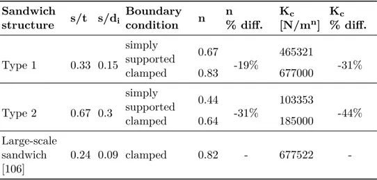
where n is a non-dimensional parameter. Meyer’s contact law refers to static contact conditions; therefore, its application to impact events is subjected to some limitations. In general, the impact response of sandwich panels is dependent on wave propagation effects, especially through the core thick-ness [47]. Nonetheless, it was demonstrated [48] that when the impactor mass is large, compared to the target panel, and when the impact velocities are low, compared to the wave velocity in the target medium, quasi-static approximations yield adequately accurate results. The energy absorbed in contact effects is obtained integrating Meyer contact law, between 0 and the maximum indentation (αmax), obtaining the following result:
Ecn = ∫ αmax 0 P dα = P 1+n1 max (n + 1)K 1 n c . (2.40)
Neglecting the membrane effects (Km = 0) and combining equations 2.37, 2.38 and 2.40, the initial kinetic energy in equation 2.36 can be expressed
as: 1 2mv 2= E b+ Esh+ Ecn= 1 2 Pmax2 Kbs + P 1+n1 max (n + 1)K 1 n c . (2.41)
The energy balance model allow the evaluation of the maximum contact force, provided that the required structure properties are known.
2.3.4 Fatigue behaviour of sandwich structures
In numerous real applications, repetitive dynamic loads act on sandwich structures, which may lead to fatigue phenomena. Fatigue response and fa-tigue life prediction is a complex and troublesome subject even for traditional materials but it gets even more challenging for sandwich structures, where infinite combinations of skin and core materials are possible and numerous damage mechanisms may arise, interacting with each other and affecting in different ways the fatigue response.
Unlike other loading conditions, sandwich structures fatigue behaviour can-not be analysed with a standard procedure nor univocal fatigue life predic-tion is viable. Therefore, the issue of sandwich structure fatigue response will be examined by presenting some approaches applied in scientific literature, which cannot be exhaustive for all possible combinations and conditions but provide useful insight on the topic.
An overall review of the main approaches for the evaluation of fatigue be-haviour of foam and honeycomb sandwich structures was provided by Sharma et al. [49], who highlighted that the majority of scientific works focus on fa-tigue response of laminates rather than sandwich structures. When it comes to all-metal sandwich structures, the fatigue-related scientific works are even fewer. A common approach to investigate fatigue life is based on S-N curves, which are derived from experimental tests. Kanny and Mahfuz [50] tested
sandwich panels with GFR skins and PVC foam core, under three-point fatigue bending. They fitted the experimental points with a logarithmic function, of the type:
log ∆σ =−1
mlog N +
log C
m (2.42)
where ∆σ is the stress range and C and m are empirical constants. Thus the obtained expression can provide a prediction for fatigue life for sandwich panels and conditions similar to the investigated ones.
Burman and Zenkert [51] introduced another data-fitting method, based on a two parameter Weibull function. They investigated sandwich structures with polymeric (PVC and PMI) foam core and fibre-reinforced facings under four-point fatigue bending. They observed that the failure mode for the applied load was core shear and they expressed the fitting Weibull function in terms of shear stress, as follows:
τ (N ) = τth+ (ˆτ − τth) e− log(
N a)
b
(2.43) where τth is the endurance limit, ˆτ is the static stress level, a and b are
fitting parameters for the curve, obtained by a quadratic error minimisation procedure. As for the previous case, the Weibull function can be used for fatigue life evaluation, provided that the required structure parameters are known after an extensive experimental campaign.
The Weibull fitting function was applied by the same authors [52] also for undamaged and damaged sandwich panels made of Nomex honeycomb core and carbon fibre epoxy prepegs skins. In order to account for the defects presence, a static strength reduction factor was suggested.
The same approach was extended by Belingardi et al. [53] to sandwich panels with aluminium honeycomb core and carbon-fibre reinforced facings, subjected to four-point fatigue bending. They proved that Burman’s [52]
method for fatigue life prediction of damaged specimens does not yield ac-ceptable results. The main reason for this conclusion lies probably in the significant difference of collapse modes for non-defected and defected speci-mens.
This proves that theoretical considerations for sandwich structures cannot be easily generalised and need to be supported by experimental evidence. Other procedures developed for sandwich structures fatigue life assessment, evaluate the strength or the stiffness degradation. For both methods, the evaluation of parameters involved in strength ad stiffness degradations is complex and requires to be calibrated for each structure type. In addition, stiffness degradation is not registered for all kinds of sandwich structures. Another perspective on sandwich structures fatigue response was offered by Harte et al. [54], who analysed the fatigue strength of all-aluminium sandwich structures with foam core under four-point fatigue bending. For each failure mode experienced by specimens in the considered conditions, they adapted the known formulations for static collapse strength by replacing the static strength of core and facing with their endurance strengths. This approach allowed the identification of fatigue failure maps, which were in good accordance with experimental results and therefore provide an effective tool for sandwich design.
2.3.5 Failure modes of sandwich structures
A thorough knowledge of sandwich failure modes is required to properly design them, by a correct prediction of their strength, and to aid an intel-ligent selection of the constituent materials. Scientific literature has widely investigated sandwich structures collapse [55], [56], which is produced by the failure of one of their constitutive parts: skins, core or bonding layer. For each component, failure can occur with different modes, depending on
the boundary conditions and on the characteristics of the parts. The main failure modes for sandwich skins and core are summarised below.
• Face yielding. Skins can fail when the axial stress σx in one of the skins equals the in-plane strength σf y of the face material
σx= σf y. (2.44)
In three-point bending conditions, for instance, one of the skin is sub-jected to tension and the other to compression. Depending on the material, tension and compression may produce different risk level: e.g. for composite facings, compression is more critical whereas for metal skins, tension is more likely to produce the failure.
• Face wrinkling. A compression loading acting in the in-plane direction of one of the skins can produce a local buckling of the facings with a wavelength grater than the cell width, when the core has a cellular structure. Buckling deformation can be directed both in towards the core or outwards, depending on the bonding strength and on the core stiffness in compression. The simplest solution for the critical wrinkling stress, was derived by Allen [43], by modelling the facing as an infinitely long strut attached to an elastic foundation extended to infinity on one side of the strut.In similar conditions, the critical compressive stress for wrinkling σf w is:
σf w= 3 [12(3− νcxz)2(1 + νcxz)2] 1 3 E 1 3 fE 2 3 3 (2.45)
where νcxz is the out-of-plane Poisson’s ratio of the core and E3 is the out-of plane Young’s modulus of the core.
• Intra-cell dimpling. When the core has a cellular structure, like a honeycomb, compression acting in-plane on the skins may result in
buckling where the facing is unsupported by the core cells walls. The critical in-plane stress in the skin for intra-cell dimpling σf i is:
σf i= 2Ef x 1− νf xy2 ( 2t s )2 (2.46) where νf xy is the Poisson’s ratio of the skin in the axial direction and s is the core cell size.
• Core shear. One of the most common failure mode observed in sand-wich structures is produced by shear in the core. As observed in sec-tion 2.3.1, in a sandwich beam subjected to three-point bending, the shear stress along the core thickness is constant, if the facings are sig-nificantly stiffer and thinner than the core. In this case, the mean shear τcxz stress in the core is expressed by equation 2.17. Core shear failure occurs when the applied stress τcxz equals the shear strength of the core τcs:
τcxz= τcs (2.47)
• Local indentation. The action of a loading element with a small contact surface compared to the core thickness, may provoke the local inden-tation of the sandwich panel, after core crushing under the indenter. An empirical approach used to predict the failure for local indentation, assumes that, when the indenter is a cylinder, such as during a three-point bending test, the compressive stress in the core σz is the ratio between the applied load P and the contact length l. Consequently, the local indentation occurs when the compressive stress in the core equals the out-of-plane compressive strength σcc of the core:
The described failure modes are schematised in Figure 2.11.
Figure 2.11. Sandwich structures failure modes [56].
2.4 Applications of sandwich structures
The demand for sandwich structures is increasing in all fields, due to the growing need of high-performance lightweight materials.
Sandwich structures were first used for military purposes during World War II: the Mosquito aircraft of the Royal Air Force is recognised as the first ex-ample of sandwich construction structural application [57], with the majority of its components made with plywood-based sandwich structures.
Since then, sandwich structures concept spread in all sectors: marine, auto-motive, railway, aeronautical, aerospace, buildings, energy production, pack-aging, furniture, are only some examples of fields which make large use of sandwich structures to cope with different requirements, ranging from weight reduction to temperature resistance, from acoustic insulation to chemical compatibility.
A general and exhaustive review of all possible sandwich structures appli-cations lies outside the scope of the current thesis. On the other hand, an insight of lightweight sandwich structures applications in the marine field is
![Figure 2.15. Hybrid joint area and large-scale experimental setup of ref.[66], reprinted with permission from Elsevier.](https://thumb-eu.123doks.com/thumbv2/123dokorg/4574645.38437/56.748.100.623.588.844/figure-hybrid-joint-large-experimental-reprinted-permission-elsevier.webp)
![Figure 2.16. Possible configurations for SCS in a RoRo deck [69].](https://thumb-eu.123doks.com/thumbv2/123dokorg/4574645.38437/59.748.139.662.437.759/figure-possible-configurations-scs-in-a-roro-deck.webp)
![Figure 2.18. Sandwich barrier concept, reprinted from [72] with permission from Elsevier.](https://thumb-eu.123doks.com/thumbv2/123dokorg/4574645.38437/61.748.172.611.643.849/figure-sandwich-barrier-concept-reprinted-permission-elsevier.webp)
![Figure 2.22. Traditional design of a hoistable car deck and two alternatives with steel sandwich structures suggested in Ref.[40].](https://thumb-eu.123doks.com/thumbv2/123dokorg/4574645.38437/66.748.168.538.148.560/figure-traditional-design-hoistable-alternatives-sandwich-structures-suggested.webp)


![Table 3.6. Out-of-plane displacement w b measured on CT images. Sandwich structure Impact energy[J] w b [mm] Type1 81 5.02 Type2 81 5 Type3 210 4.55 Type4 210 7.2 Type 5 210 6.08 Type 6 210 5.28](https://thumb-eu.123doks.com/thumbv2/123dokorg/4574645.38437/99.748.208.580.204.381/table-displacement-measured-images-sandwich-structure-impact-energy.webp)