UNIVERSITA' DEGLI STUDI DI MESSINA
DIPARTIMENTO DI SCIENZE CHIMICHE, BIOLOGICHE,FARMACEUTICHE ED AMBIENTALI
Corso di Dottorato in Scienze Chimiche – XXXIII Ciclo
Curriculum Progettazione, Sintesi, Analisi e Proprietà di Sistemi Molecolari Funzionali
Photocatalytic CO
2Reduction by Multinuclear
Metal Complexes - A Journey Towards
High-Nuclearity Supramolecular Photocatalysts
Ambra Maria Cancelliere
Coordinator Prof.ssa Paola Dugo
Supervisor
Prof. Sebastiano Campagna
Introduction 1
Outline of the thesis 2
References 4 Chapter 1 Artificial Photosynthesis 5 References 8 Chapter 2
Photoinduced Electron Transfer 9
2.1 The Marcus Theory 9
2.2 Electron Transfer via Hopping or Tunnelling (or
Superexchange) Mechanism 13
References 21
Chapter 3
Properties of Ruthenium Polypyridine Complexes 23
References 28
Chapter 4
Basic Concepts about CO2 Reduction 31
4.1. Introduction 31
4.2. Redox photosensitizer 35
4.3 Catalysts 37
4.4 Electron Donors 38
4.4.2 Dihydrobenzoimidazole Derivatives 40
References 41
Chapter 5
Photocatalytic CO2 Reduction by Multinuclear Metal Complexes 45
5.1 Ligand bpy2Ph and its metal complexes 46
5.1.1 Synthesis of ligand bpy2Ph 46
5.1.2 Synthesis of RuRe complex 47
5.1.2.1 Absorption Spectra and Photophysical Properties 49
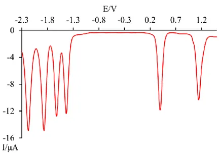
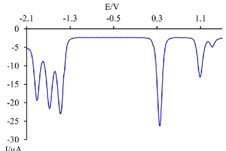
5.1.2.2 Redox Properties 52
5.1.2.3 Photocatalytic Analysis 55
5.2 Ligand bpy3Ph and its metal complexes 58
5.2.1 Synthesis of ligand bpy3Ph 58
5.2.2 Synthesis of RuRe2 and Ru2Re Supramolecular Complexes 59
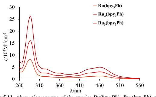
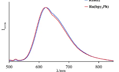
5.2.2.1 Absorption Spectra and Photophysical Properties 61
5.2.2.2 Redox Properties 65
5.2.2.3 Photocatalysis Studies 69
5.2.3 Synthesis of Ru2Ru Supramolecular Complex 75
5.2.3.1 Absorption Spectra and Photophysical Properties 76
5.2.3.2 Redox Properties 78
5.2.3.3 Photocatalytic Analysis 79
5.3 Ligand bpy4Ph and its metal complexes 80
5.3.1 Synthesis of ligand bpy3Ph 80
5.3.2 Synthesis of Ru3Re Supramolecular Complex 81
5.3.2.1 Absorption Spectra and Photophysical Properties 83
5.3.2.2 Redox Properties 86
5.3.2.3 Photocatalysis Analysis 87
5.3.3 Synthesis of Ru3Ru Supramolecular Complex 88
5.3.3.2 Redox Properties 91
5.3.3.3 Photocatalytic Analysis 92
5.4 Second generation: dendritic mixed metal photocatalysts 93
5.4.1 Synthesis of RuRe3 and RuRe6 Supramolecular Complexes 93
5.4.1.1 Absorption Spectra and Photophysical Properties 102
5.4.1.2 Redox Properties 106
References 112
Chapter 6
Conclusions 115
Chapter 7
PhotoElectrocatalysis for CO2 Reduction – An Appendix 117
6.1 Preparation of modified photoelectrodes FTO/NiO-Dye/Catalyst 120
6.2 Spectroscopic characterization of molecular components and of
the FTO/NiO-P1/Re electrode 121
6.3 Electrochemical characterization of FTO/NiO/Re and
FTO/NiO-P1/Re electrodes 124
6.4. Conclusions and Perspectives
References
131 133
Chapter 8
Experimental Section 135
8.1 Materials and Methods 135
8.2 CO2 Photoreduction 136
8.3 CO2 PhotoElectroreduction 137
8.3.1 Modified (photo)electrode fabrication 137
8.4. Syntheses 139
8.4.2 Syntheses of the Photosensitizer Moieties 141
8.4.3 Syntheses of the Final Integrated
Photosensitizer(s)-Catalyst(s) Complexes 143
8.4.4 Syntheses of the Final Integrated dendrimer
Photosensitizer(s)-Catalyst(s) Complexes 145
8.4.5 Syntheses Catalysts Complexes 147
8.4.6 Syntheses of the Sacrificial Agents 148
8.5 NMR Characterization
References
151 155
Introduction
We have always held to the hope, the belief, the conviction that there is a better
life, a better world, beyond the horizon.
Franklin D. Roosevelt
The fossil fuels have been, until now, the most exploited energy source. The growth of world population, together with the increasing demand of energy, needs, economic and industrial developments have caused the increasing in the global energy consumption. The extensive fossil fuels consumption causes an increase in the atmospheric CO2, that induces several problems such as the
global warming and the greenhouse effect. There are a better life and a better
world beyond the horizon. We can reach them having the research focused on
the green and sustainable energy sources. There are various kinds of energy sources suitable to this aim, but the solar energy is the most promising. Solar light is renewable and environmentally clean, inexpensive, available everywhere and abundant.1,2 Moreover, the use of CO2 to obtain energy-rich compounds,
like CO and HCOOH, using solar light,3 has been scientifically demonstrated. Increasing the field of research on this alternative energy source can gives us the possibility that reaching this horizon could not be just a hope.
So, the aim of my research topic during the three-year PhD course in Chemical Science was the synthesis and study of new multinuclear metal-based supramolecular systems that can integrate all the principal components needed for the photocatalytic reduction of CO2. Most of my research work has been
performed in the Photochemistry group of the Department of Chemical, Biological, Pharmaceutical and Environmental Science of University of Messina under the supervision of Prof. Sebastiano Campagna. During this period, I have
2
performed the syntheses and the photophysical and redox studies of all the metal complexes (including the various building blocks) reported in this thesis. Moreover, I performed the photocatalysis experiments on these complexes in the Tokyo Institute of Technology (Japan) under the supervision of prof. Osamu Ishitani, also taking advantage of a Italy-Japan collaborative research project. To complement the work on integrated systems for CO2 photocatalysis, an
investigation on the PhotoElectroreduction of CO2 was performed in Universitè
de Paris under the supervision of Dr. Marie-Pierre Santoni, where I performed the syntheses of suitable catalysts for the CO2 reduction, the assembly of
multilayer electrodes and the electrochemical analysis on these electrodes.
Outline of the thesis
In Chapter 1 it is exposed a brief overview on the artificial photosynthesis and the principal elements that should compose an artificial photosynthetic system.
Chapter 2 summarizes the basic information about the electron transfer process,
fundamental in the CO2 reduction process.
Chapter 3 describes the principal photochemical and photophysical properties of
the ruthenium polypyridine complexes, crucial element of the supramolecular systems described in this thesis.
In Chapter 4 the bases of the CO2 reduction are described, together with the key
elements that compose an efficient system for CO2 reduction and their principal
characteristics and properties.
Chapter 5 presents all the synthesized supramolecular complexes and their
photophysical and redox properties. In this chapter also the results of the photocatalysis experiments are exposed. The complexes synthesized present three different bridging ligands, which allow the possibility to build integrate photosensitizer-catalyst (PS-CAT) systems with different ratio of Ru(II)-based PS and Ru(II)- or Re(I)-based CAT subunits. The bridging ligands used are different from those usually used in this field in literature, since they guarantee a
3 larger separation between the photosensitizer and catalyst metal subunits. This can also have an impact on future developments of this field.
In Chapter 6 the principal results obtained with the supramolecular systems described in detail in Chapter 5, that is the main output of the thesis, are summarized.
Chapter 7 is a brief appendix on PhotoElectrocatalytic systems, a parallel
approach we used towards the preparation of metal-based integrated systems for CO2 photoreduction. In this chapter, the construction of NiO electrodes
functionalized with suitable photosensitizers and catalysts and their principal redox characteristics are reported.
Chapter 8 is the experimental section of this thesis, where the methods and
4
References
1. (a) N. Armaroli, V. Balzani, Angew. Chem., Int. Ed., 2007, 46, 52-66; (b) M. H. V. Huynh, T. J. Meyer, Chem. Rev., 2007, 107, 5004-5064; (c) J. P. McEvoy, G. W. Brudvig, Chem. Rev., 2006, 106, 4455-4483; (d) M. Wasielewski, Acc. Chem. Res., 2009, 42, 1910-1921; (e) D. Gust, T. A. Moore, A. L. Moore, Acc. Chem. Res., 2009, 42, 1890-1898; (f) C. Herrero, A. Quaranta, W. Leibl, A. W. Rutherford, A. Aukauloo, Energy Environ.
Sci., 2001, 4, 2353-2365.
2. (a) N. Armaroli, V. Balzani, Energy for a Sustainable World: From the Oil
Age to a Sun-Powered Future, Wiley-VCH, Weinheim, 2011; (b) N.
Armaroli, V. Balzani, N. Serpone, Powering Planet Earth, Wiley-VCH, Weinheim, 2013.
Artificial Photosynthesis
The sun represents an inexhaustive energetic source: it sends on the Earth surface every hour more energy than that consumed all over the word in one year. Nature has taken advantage of this kind of energy in natural photosynthetic processes through the conversion of water and CO2 in O2 and simple sugars (as C6H12O6),
since ancient times.1 In natural photosynthetic organisms, such as plants and bacteria, the light conversion in useful energy-rich chemicals occurs via a series of energy and electron transfer processes. In a photosynthetic system, photosystem I (PSI)2 and photosystem II (PSII)3 play the role of collecting sunlight and transferring it (in the form of electronic energy) towards the reaction center, where charge separation takes place. A manganese calcium cluster acts as catalyst for the water oxidation (see eqn. 1).4 On the other side, the reduction of NAD+ to NADPH (useful to produce carbohydrates in the dark cycle) occurs.
6 𝐶𝑂2+ 6 𝐻2𝑂 ℎ𝜈→ 𝐶6𝐻12𝑂6+ 6 𝑂2 eqn. 1
In the past decades, by mimicking natural systems, artificial photosynthetic systems have been investigated.5 It should be noted that natural systems are incredibly complex and it is almost impossible to mimic exactly their components. On the other side, natural photosynthesis is rather inefficient for an industrial use, so the aim of artificial photosynthesis is to borrow mechanistic information from the natural photosynthesis and use the basic functions to design more efficient ones. In order to replicate the function of the natural photosynthetic systems, the artificial photosynthetic ones must include an antenna system, a reaction center and multielectron catalysts for the oxidation and reduction processes, as shown in Figure 1.1.
6
An efficient antenna system should be based on a large number of chromophores that should absorb a wide portion of the solar light and, by a series of energy transfer, funnelling the light to a specific site: the energy trap.
The reaction center is based on redox-active species (the energy trap and the electron acceptor and donor subunits). The goal of the reaction center is obtaining a charge-separated state via a series of electron transfer processes that allow the transformation of electronic energy in redox energy.
Figure 1.1. Schematic representation of an artificial photosynthetic system. On the two sides of the reaction center there are two different catalysts able to accumulate holes and electrons needed respectively for the oxidation and the reduction processes.
In artificial photosynthesis, the mainly reactions investigated are the water splitting6 and the CO2 reduction,7 but also other kinds of reactions have been
studied.8,9
All the previously described components of the artificial photosynthetic systems are multicomponent systems themselves, so a hierarchical organization is required.10
7 The best approach to design a rational system that can act as an efficient photosynthetic system is studying all the components separately and then connect them in single supramolecular entities in a functionally-integrated manner.
8
References
1. V. Krewald, M. Retegan, D. A. Panzalis, Solar Energy for Fuels, Springer, 2015, 23-48.
2. A. Amunts, O. Drory, N. Nelson, Nature, 2007, 447, 58–63.
3. Y. Umena, K. Kawakami, J. R. Shen, N. Kamiya, Nature, 2011, 473, 55–60. 4. J. P. McEvoy, G. W. Brudvig, Chem. Rev., 2006, 106, 4455–4493.
5. (a) H. Dau, E. Fujita, L. Sun, ChemSusChem, 2017, 10, 4228–4235; (b) B. Zhang, L. Sun, Chem. Soc. Rev., 2019, 48, 2216-2264.
6. Y. Tachibana, L. Vayssieres, J. R. Durrant, Nature Photonics, 2012, 6, 511-518.
7. A. Corma, H. Garcia, Journal of Catalysis, 2013, 308, 168-175.
8. K. E. Dalle, J. Warnan, J. J. Leung, B. Reuillard, I. S. Karmel, E. Reisner,
Chem. Rev., 2019, 119, 2752–2875.
9. Y. Amao, ChemCatChem, 2011, 3, 458 – 474.
10. S. Serroni, S. Campagna, F. Puntoriero, F. Loiseau, V. Ricevuto, R. Passalacqua, M. Galletta, C. R. Chimie, 2003, 6, 883–893.
Photoinduced Electron Transfer
The electron transfer process (ET) plays a key role in chemical and biological systems, such as in synthetic assemblies for solar energy conversion and information technology and in natural photosynthetic systems.1,2,3
In a generic electron transfer reaction, there are two species acting one as electron acceptor (A) and the other one as electron donor (D). The diffusion is the limiting factor that influences the process rate when A and D are dispersed in solution (intermolecular electron transfer). Such a process leads to the formation of A- and D+ ions. On the other hand, if a covalent link connects the electron donor and acceptor, the electron transfer process is no more influenced by the diffusion and can be more rapid (intramolecular electron transfer). The charge separated D+-A- supermolecular species is so formed.
Photoinduced Electron Transfer (PET) is a case where A or D are excited species, formed by light absorption or energy transfer. In this case, the process is easier than the process involving the species in the ground state because the excited state species are better oxidants and reductants.
2.1 The Marcus Theory
The parameters that influence the rate constant of the electron transfer are explained in the classical Marcus theory.4 In this theory the potential energy surfaces (the Gibbs energy profiles) are represented as parabolas. In Figure 2.1 it is shown the parabolic potential energy curves for a generic electron transfer process. In this figure, ΔG* represents the activation energy for the electron transfer reaction; ΔG0 is the reaction driving force (the difference in energy between the minima of the equilibrium curves); λ is the reorganization energy.
10
The last parameter is graphically defined in Figure 2.1 and mathematically by the eqn. 1:
𝜆 = 𝜆𝑖+ 𝜆𝑜 eqn. 1
Where λi deals with the bond length and the vibrational mode of the reactants
and λo is related to the reorganization and to the parameters of the solvent and it
is given by the eqn. 2:
λo = 𝑒2( 1 𝜀𝑜𝑝− 1 𝜀𝑠) ( 1 2𝑟𝐴+ 1 2𝑟𝐷− 1 𝑟𝐷𝐴) eqn. 2
In this equation, reactants are approximated to be spheres in a dielectric continuum; εs and εop are respectively the static and optical solvent dielectrics;
rD and rA are the donor and acceptor radii and rDA represents the distance
center-to-center between the reactants.
Figure 2.1. Parabolic potential energy curves for the electron transfer: i
represents the initial state (D-A) and f is the final state (D+-A-).
From eqn. 1 and 2 it is possible to assume that:
1. The radii of D and A are inversely related with the reorganization energy (due to a less interaction between solvent and ions);
11 2. When distance between donor and acceptor decrease, the value of λ
decreases too;
3. The reorganization energy value decreases when there are solvents with a high dielectric constant (ε2).
The eqn. 3, according to the Fermi Golden Rule, represents the rate constant for the electron transfer (here a semi-quantomechanical approach, inherently non-adiabatic, is considered):5
𝐾𝑒𝑙 = 4𝜋
ℎ |𝐻𝐸𝑇|
2 𝐹𝐶𝑊𝐷 eqn. 3
HET is a matrix element representing the electronic coupling for the electron
transfer reaction between the reactant and product states. This coupling depends on the overlapping region magnitude between acceptor and donor orbitals. A small value of HET implies that the product and reactant energy surfaces (see
Figure 2.1) do not present strong interactions and the ET process is called non-adiabatic. On the contrary, if the HET value is quite large, the energy surfaces
interact significantly and the electron transfer is named adiabatic.
Figure 2.2. In the panel a), b) and c) the different region in the Marcus theory
are shown. Panel d) shows the dependence of the electron transfer rate on the driving force.
12
The FCWD term (Franck-Condon weighted density of states) in eqn. 3 is a thermally averaged overlap which connects the initial and final vibrational wavefunctions. This term can be expressed, using a single-mode approximation with quantum mode of frequency νi, by the equation 4:6,7
𝐹𝐶𝑊𝐷 = ( 1 4𝜋𝜆0𝐾𝐵𝑇) 1 2 ∑ 𝑆𝑚 𝑚 𝑒−𝑆 𝑚! exp [− (∆𝐺0+𝜆 0+𝑚ℎ𝜈𝑖) 2 4𝜆0𝐾𝐵𝑇 ] eqn. 4 Where m is the number of vibrational states in the final state, ΔG0 is the
variation of the free energy, λo is related to the reorganization energy of the
solvent (outer-sphere) and S (the Huang-Rhys factor) is expressed by the eqn. 5: 𝑆 = 𝜆𝑖
ℎ𝜈𝑖 eqn. 5
The S parameter is dimensionless and is proportional to the inner-sphere reorganization energy λi.6,7
The FCWD term takes note of the nuclear reorganization and the driving force effects simultaneously. This parameter can be expressed by the eqn. 6 considering the high-temperature limits, yielding to the classical expression of the Marcus theory:7,8
𝐹𝐶𝑊𝐷 = ( 1 4𝜋𝜆𝐾𝐵𝑇) 1 2 exp [−(∆𝐺0+𝜆) 2 4𝜆𝐾𝐵𝑇 ] eqn. 6
Specifically, eqn. 6 connects -ΔG0 term with the reorganization energy λ, predicting three different kinetic regimes (as exposed in Figure 2.2, assuming that the final potential energy surface is only vertically shifted in respect to the initial surface):7,8,9
• A “normal” regime when -ΔG0 is smaller than λ (Figure 2.2a), the rate
constant for the electron transfer increases as ΔG* diminishes;
• An activationless regime when -ΔG0 is equal to λ, ΔG* = 0 and the rate
13 2.2b);
• An “inverted” regime when -ΔG0 is larger than λ, the activation energy
should increase again even though the driving force becomes even more negative (Figure 2.2c); kET decreases when the process becomes more
exergonic (Marcus inverted region).7-9
2.2 Electron Transfer via Hopping or Tunneling (or Superexchange)
Mechanism
What discussed till now refers to a generic case of electron transfer. Now it will be examined the case where one or more subunits called bridge (B) link the electron donor (D) and the electron acceptor (A). The characteristics of the bridge (i.e. its nature and molecular orbitals) strongly influence the processes of charge separation and recombination.
The electron transfer in D-B-A systems may involve two kinds of mechanisms: hopping or tunneling.3-10
The hopping mechanism is presumed to occur when the bridge’s LUMO is energetically close to the donor’s one and its state is thermodynamically accessible. In this mechanism the bridge is reduced or oxidized via a multistep charge transport in order to obtain a charge separation.
Instead, in the tunneling mechanism it must be introduced the superexchange model, in which bridge-involving states are not thermodynamically available because too high in energy with respect to the donor- and acceptor-centred states. However, despite the bridge makes the electronic coupling between the donor and acceptor possible, it is never directly oxidized or reduced (in other words, the bridge-involving states behave as virtual states).11 As mentioned
above, it should be expected that the electron transfer via tunneling mechanism is slower than via hopping, but in some D-B-A systems a mixture of both mechanisms can take place.
14
The next part of this paragraph will be focused on the tunnelling (or superexchange) mechanism. In this case the orbitals of D, B and A are involved in the formation of virtual states (for the superexchange mechanism model) via two main pathways (see Figure 2.3):
• The electron transfer (ET) pathway, where a virtual D+-B--A participates
state, involves the lowest virtual molecular orbital centred on the bridge; • The hole transfer (HT) route, where there is the participation of a D-B+-A
-virtual state (the highest molecular orbital occupied centred on the bridging ligand).
Figure 2.3. Schematic representation of the electron transfer via superexchange
model in D-B-A systems. The excited blue states are the possible virtual state involved in the electron and hole transfer.
In the case where there is no direct coupling between donor and acceptor (or it is negligible) the superexchange coupling HET is mediated by the bridge as shown
in eqn. 7:12,13,14
𝐻𝐸𝑇 = 𝐻𝑒+ 𝐻ℎ =𝐻𝑖𝑒𝐻𝑓𝑒
∆𝐸𝑒(𝑖𝑓)+
𝐻𝑖ℎ𝐻𝑓ℎ
∆𝐸ℎ(𝑖𝑓) eqn. 7
Where Hie and Hfe are matrix elements referring to the couplings between the
initial and final states with the electron transfer virtual state D+-B--A, while H ih
and Hfh are the corresponding coupling with the hole transfer virtual state D-B+
15 ET and HT and the initial or final state. In the eq. 7 is clearly evidenced that both HT and ET superexchange routes could be involved in the thermal electron transfer reactions.
In general, in the photoinduced electron transfer processes the charge separated species can be obtained via a reductive or an oxidative mechanism.3,15
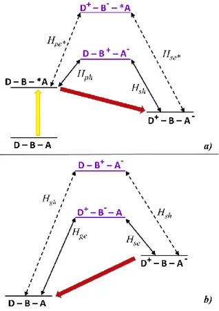
Figure 2.4. Schematization of the states which take part in an oxidative electron
transfer mechanism mediated by superexchange in a typical D-B-A molecular dyad. The double arrows represent the couplings among the states. In the panel a) shows a yellow arrow representing the light effect and it illustrates the states involved in the forward electron transfer process (the photoinduced charge separation); in the panel b) the back electron transfer process is shown (the charge recombination process). The state D-B+-A- in the panel b) does not
appear in the panel a) because it cannot assist the forward process.
In the oxidative electron transfer process, it is possible considering the electron moving from the D excited state to the A ground state (as shown in Figure 2.4a). The only virtual states possibly involved in the charge separation are the ones that grant a connection through the bridge between the initial *D-B-A
16
photo-excited state with the charge separated D+-B-A- state, via two sequential
one-electron transfer steps. The virtual state D-B+-A- is not a superexchange mediator because it involves a two-electrons transfer. Moreover, the *D-B+-A -excited hole transfer state is too high in energy, so its contribution to the charge separated state formation can be neglectable.16 For these reasons, the virtual state D+-B--A is the most efficiently involved in the charge separated state formation.
Generally, the matrix element for the superexchange electronic coupling involved in an oxidative charge separation process (HCSOPET) can be expressed
by the eqn. 8:17 𝐻𝑂𝑃𝐸𝑇𝐶𝑆 =𝐻𝑝𝑒𝐻𝑠𝑒 ∆𝐸𝑒(𝑝𝑠) +𝐻𝑝ℎ∗𝐻𝑠ℎ∗ ∆𝐸ℎ∗(𝑝𝑠) eqn. 8
Where Hpe, Hse, Hph* and Hsh* are defined in Figure 2.4a and represent the
virtual states intermediate coupling matrix elements and ΔEe(ps) and ΔEh*(ps)
represent the energy gap between the virtual states and the initial or final states of the process. The first term of the eqn. 8 is expected to be the dominating one and, for this reason, it is reasonably predictable that the charge separation, in photoinduced oxidative electron transfer, takes place by an electron transfer superexchange path.3,15,17
On the other hand, in the reductive mechanism for the photoinduced electron transfer, the excited species is the electron acceptor, which is reduced by the electron donor in the ground state. Also in this case, the only virtual states possibly involved in the charge separation are the ones that grant a connection through the bridge between the initial D-B-*A photo-excited state with the charge separated D+-B-A- state, via two sequential one-electron transfer steps. Among all the possible virtual state represented in Figure 2.5a, the D-B+-A -state is not a superexchange mediator because it involves a two-electrons transfer; the D+-B--*A excited state is too high in energy, so its contribution to the charge separated state formation can be neglectable;3 so, the virtual state
17 D-B+-A- is the most efficiently involved in the charge separated state formation.
The superexchange electronic coupling matrix element for the reductive charge separation process (HCSRPET) can be expressed by the eqn. 9:
𝐻𝑅𝑃𝐸𝑇𝐶𝑆 =𝐻𝑝ℎ𝐻𝑠ℎ
∆𝐸ℎ(𝑝𝑠) +
𝐻𝑝𝑒∗𝐻𝑠𝑒∗
∆𝐸𝑒∗(𝑝𝑠) eqn. 9
Where Hph, Hsh, Hpe* and Hse* are defined in Figure 2.5a and represent the
virtual states intermediate coupling matrix elements and ΔEh(ps) and ΔEe*(ps)
represent the energy gap between the virtual states and the initial or final states of the process.
Figure 2.5. Schematization of the states which take part in a reductive
photoinduced electron transfer process mediated by superexchange in a typical D-B-A system. The double arrows represent the couplings among the states. In the panel a) shows a yellow arrow representing the light effect and it illustrates the states involved in the forward electron transfer process; in the panel b) the back electron transfer process is shown.
18
The first term of the eqn. 9 is expected to be the dominating one, because of the major contribution of the D-B+-A- state; for this reason it is reasonably predictable that the charge separation, in photoinduced reductive electron transfer, takes place via an hole transfer superexchange path.3,15,17
Also in the charge recombination processes, both the hole and electron transfer pathways should be considered (see Figure 2.4b and 2.5b).
The bridge is usually based on aromatic units or π-conjugated systems (e.g. double bonds). The MOs energy level and the HOMO-LUMO energy difference in the bridge should decrease by increasing the extension of the conjugated system size.3,10 So, the model of the superexchange might be modified when the bridge is composed by several repeating units (the so called “modular” bridge). It is now described an example of oxidative electron transfer in a dyad with a modular bridge based on three repeating units schematized in Figure 2.6. It can be noted that, even if the following example is referred to an oxidative mechanism, the same consideration can be done also for the reductive electron transfer or charge recombination (applying the appropriate scheme).
Figure 2.6. Schematization of the superexchange interactions mediating an
oxidative photoinduced electron transfer in a system with a modular bridge composed by three repetitive units. The excited blue states are the possible virtual state involved in the electron and hole transfer and the double arrows represent the couplings among the states.
The charge separation rate matrix element is calculated by the eqn. 10:3 𝐻𝑒 =𝐻𝑖1𝐻12𝐻23𝐻3𝑓
19 Where Hi1 and H3f represent the coupling between the states localized on the
bridge and, respectively, the initial and final sates, H12 = H23 are the coupling
between the close units of the bridge and ΔE represents the energy gap between the bridge-localized virtual states and the initial or final states of the process. For n repeating units the eqn.10 becomes:
𝐻𝑒 =𝐻𝑖1𝐻𝑛𝑓 ∆𝐸 ( 𝐻𝑚𝑛 ∆𝐸 ) 𝑛−1 eqn. 11
The first term of eq. 11 represents the coupling between the bridge units and the initial or final states and the second term gives the interaction propagation along the bridge (given that H12 = H23=…=Hmn). Ideally, ΔE is not dependent from the bridge length when there are weak interactions between the bridge units.3 So, the electronic matrix element should exponentially decrease with the number of modules n of the bridge:
𝐻𝑒 = 𝐻𝑒(0) exp [−𝛽𝑛
2 (𝑛 − 1)] eqn. 12
In eqn. 12, He(0) is the coupling term for a single-module dyad and is expressed by the eqn. 13 and βn represents the decay coefficient (eqn. 14):
𝐻𝑒(0) =𝐻𝑖1𝐻1𝑓
∆𝐸 eqn. 13
𝛽𝑛 = 2 ln ∆𝐸
𝐻𝑚𝑛 eqn. 14
In the case of electron transfer in presence of modular bridges the process rate constant (KET) decreases exponentially with the distance between the donor and acceptor (r) as expressed by the eqn. 15:
𝐾𝐸𝑇 = 𝐾 0𝐸𝑇exp[−𝛽(𝑟 − 𝑟0)] eqn. 15 𝛽 = 2 𝑟𝑚ln ∆𝐸 𝐻𝑚𝑛 eqn. 16
20
In eqn. 16, rm represents the length of one bridge unit. It is evident from eq. 16
that β, in modular-bridge systems, depends on ΔE; consequently, it changes by using different donor or acceptor units and it can explain how the modular bridge mediates the donor-acceptor interaction. The equations 10 – 16 evidence also that the bridges should, preferably, have high-energy HOMOs or low-energy LUMOs, in order to obtain a long-range hole or electron transfer.3
21
References
1. (a) M. R. Wasielewski, Chem. Rev., 1992, 92, 435-461; (b) D. Gust, T. A. Moore, A. L. Moore, Acc. Chem. Res., 1993, 26, 198-205.
2. (a) V. Balzani, Pure Appl. Chem., 1990, 62, 1099-1102; (b) T. J. Meyer, Acc.
Chem. Res., 1989, 22, 163-170; (c) J. J. Onuchic, D. N. Beratan, J. R.
Winkler, H. B. Gray, Annu. Rev. Biophys. Biomol. Struct., 1992, 21, 349-377; (d) B. Albinsson, J. Martersson, J. Photochem. Photobiol. C: Photochem.
Rev., 2008, 9, 138-155.
3. M. Natali, S. Campagna, F. Scandola, Chem. Soc. Rev., 2014, 43, 4005-4018. 4. R. A. Marcus, N. Sutin, Biochim. Biophys. Acta, 1985, 811, 265-322. 5. M. N. Paddon-Row, in: V. Balzani, Electron Transfer in Chemistry,
Wiley-VCH, Weinheim, 2001, vol. 3, p. 179.
6. (a) T. J. Meyer, Pure Appl. Chem. 1986, 58, 1193-1206; (b) P. F. Barbara, T. J. Meyer, M. A. Ratner, J. Phys. Chem., 1996, 100, 13148-13168; (c) J. R. Miller, J. V. Beitz and R. K. Huddleston, J. Am. Chem. Soc., 1984, 106, 5057-5068.
7. (a) N. Sutin, Prog. Inorg. Chem., 1983, 30, 441; (b) R. D. Cannon, Electron
Transfer Reactions, Butterworths, London, 1980; (c) L. Eberson, Electron Transfer Reactions in Organic Chemistry Springer, New York, 1987.
8. (a) R. A. Marcus, J. Chem. Phys., 1965, 43, 679-701; (b) R. A. Marcus, Disc.
Faraday Soc., 1960, 29, 21-31.
9. (a) J. Jortner, J. Chem. Phys., 1976, 64, 4860-4867; (b) V. Balzani, F. Scandola, Supramolecular Photochemistry, ed. Ellis Horwood, 1991, Ch. 5; (c) H. M. McConnell, J. Chem Phys., 1961, 35, 508-515.
10. M. Gilbert, B. Albinsson, Chem. Soc. Rev., 2005, 44, 845-862.
11. V. Balzani, P. Ceroni, A. Juris, Photochemistry and Photophysics.
Concepts, Research, Perspectives, Wiley-VCH, Weinheim, 2014.
12. (a) J. N. Onuchic, D. N. Beratan, J. Am. Chem. Soc., 1987, 109, 6771-67780; (b) K. V. Mikkelsen, M. A. Ratner, J. Phys. Chem., 1989, 93,
1759-22
1770; (c) M. D. Newton, Chem. Rev., 1991, 91, 767-792; (d) K. D. Jordan, M. N. Paddon-Row, Chem. Rev., 1992, 92, 395-410; (e) P. F. Barbara, T. J. Meyer, M. A. Ratner, J. Phys. Chem., 1996, 100, 13148-13168; (f) D. Gust, T. A. Moore, A. L. Moore, Acc. Chem. Res., 2001, 34, 40-48; (g) S. Fukuzumi, Bull. Chem. Soc. Jpn., 2006, 79, 177-195; (h) S. Wenger, Acc.
Chem. Res., 2011, 44, 25-35.
13. J. R. Winkler, H. B. Gray, J. Am. Chem. Soc., 2014, 136, 2930-2939.
14. (a) F. Scandola, C. Chiorboli, M. T. Indelli and M. A. Rampi, in Electron
Transfer in Chemistry, ed. V. Balzani, Wiley-VCH, Weinheim, Germany,
2001, ch. 2.3, vol. III; (b) J. Halpern, L. E. Orgel, Discuss. Faraday Soc., 1960, 29, 32-41.
15. A. Arrigo, A. Santoro, F. Puntoriero, P. P. Lainé, S. Campagna, Coord.
Chem. Rev., 2015, 304-305, 109-116
16. J. R. Miller, J. V. Beitz, R. K. Huddleston, J. Am. Chem. Soc., 1984, 106, 5057-5068.
17. A. Arrigo, A. Santoro, M. T. Indelli, M. Natali, F. Scandola, S. Campagna,
Properties of Ruthenium Polypyridine Complexes
Ru(II) polypyridine complexes have been widely studied in the last decades. Ruthenium, in its 2+ oxidation state, is a d6 system. Polypyridine are colourless molecules and strong field ligands. These ligands can act as σ-donor, using the orbital localized on the nitrogen atoms, and π-donor and π*-acceptor, using the orbital delocalized on the aromatic rings. A schematization of the molecular orbital (MO) diagram and the possible electronic transition of the Ru(LL)32+
complexes (where LL indicates the bidentate polypyridine ligand) is shown in Figure 3.1.
Figure 3.1. Scheme of MO with possible electronic transition.
In these complexes, which present octahedral symmetry, it is possible to observe several electron transitions with the formation of the following excited states:
24
• A Metal Centred (MC) excited state involving the promotion of an electron from the πM to σ*M orbitals;
• A Metal To Ligand Charge Transfer (MLCT) excited state involving the electron promotion from a πM metal orbital to a πL* ligand orbitals;
• A Ligand Centred (LC) excited state involving the electron promotion from πL to a πL* orbitals.
The LMCT excited state could not be observed at low energy because in low spin octahedral complexes the πM(t2g) orbital are fulfilled.
All the excited states previously described may have singlet or triplet multiplicity, the same in the MC and MLCT excited states where a large singlet-triplet mixing occurs due to a spin-orbit coupling.1,2,3,4
Ru(LL)32+ complexes (among which Ru(bpy)32+ is the most studied and could be
used as model) present a D3 symmetry.5 The π* orbitals may be symmetrical or
antisymmetrical referring to C2 rotational axis retained by each Ru(LL) unit
(respectively χ and φ, following the Orgel notation)6.
Figure 3.2. Detailed representation of MLCT transition in metal complexes with
25 Figure 3.2 shows a more detailed representation of the HOMOs (Highest Occupied Molecular Orbitals, πM a1(d) and πM e(d)), mainly localized on the
metal, and LUMOs (Lowest Unoccupied Molecular Orbitals, π∗La2(φ) and
π∗Le(φ)) mainly localized on the ligands.7,8 In such complexes the ground state is
a singlet where the electron takes up the HOMO with πM e(d)4 πM a1(d)2
electronic configuration. The photochemical and photophysical properties are determined by the lowest excited state (following the Kasha’s rule) or the upper states which can be populated (according to Boltzmann equilibrium distribution).
Figure 3.3. Schematization of two limiting cases of the relative position of MC
and MLCT or LC states.
If the lowest energy exited state is MC, as a result of a very distorted geometry of the MC state compared to the ground state along the metal-ligand vibration coordination in the d6 octahedral complexes,9 it could lead to fast non-radiative deactivation and/or ligand dissociation reaction (see Figure 3.3); for this reason, at room temperature, MC excited states lifetimes are very short, it is not possible to observe luminescence phenomena10 and bimolecular reaction does not take place.
If the lowest energy excited state does not have a high distorted geometry respect to the ground state as the MLCT and LC excited state, it could lead to a radiative decay and luminescence may also be seen (Figure 3.3).
26
The triplet MLCT excited state is more strongly influenced by the spin-orbit coupling effect than triplet LC excited state and this result in a greater radiative constant rate for the MLCT excited state. For this reason, emission from 3MLCT excited state can be observed in fluid solution at room temperature and 3LC emission is not observed (or less frequently observed) in such a condition. Instead, 3LC excited state could lead to luminescence in a rigid matrix at low temperature.
In Ru(II) polypyridine complexes the energy position of MC, MLCT and LC may be modulated by changing the ligand,11,12 because the energy of these states depends on the nature of the metal (i.e. redox properties) and the ligand (i.e. the ligand field strength and redox and intrinsic properties of the ligands). After a wide overview of the reduced and excited complexes with a variety of spectroscopic and electrochemical techniques,13 the orbital involved in the
3MLCT excited state is best described as localized on a single chelated unit.
It is possible to discuss the general properties of Ru(II) polypyridine complexes, using the [Ru(bpy)3]2+ as model.
Figure 3.4. Absorption spectrum of [Ru(bpy)3]2+ in acetonitrile solution at room
27 As shown in Figure 3.4, the absorption spectrum of [Ru(bpy)3]2+ presents at
285 nm an intense band attributed, by comparison with the spectrum of protonated bipyridine, to the spin-allowed LC π-π* transitions.14 It is also possible observing two intense bands due to the MLCT d-π* transition at 240 and 450 nm. The two small shoulders at 320 and 350 nm might be assigned to MC transitions.
In the same experimental conditions, the state which produces luminescence is a
28
References
1. G. A. Crosby, Acc. Chem. Res., 1975, 8, 231-238. 2. G. A. Crosby, Adv. Chem. Ser., 1976, 150, 149-159.
3. E. M. Kober, T. J. Meyer, Inorg. Chem., 1982, 21, 3967-3977.
4. K. Mandal, T. L. D. Pearson, W. P. Krug, J. N. Demas, J. Am. Chem. Soc., 1983, 105, 701–707.
5. D. P. Rillema, D. S. Jones, H. A. Levy, J. Chem. Soc. Chem. Commun., 1979, 849
6. L. E. Orgel, J. Chem. Soc., 1961, 3683-3686.
7. K. Kalyanasundaram, Coord. Chem. Rev., 1982, 46, 159-244. 8. R. J. Watts, J. Chem. Educ., 1983, 60, 834-842.
9. A. W. Adamson, J. Chem. Educ., 1983, 60, 797-802.
10. P. D. Fleischauer, P. Fleischauer, Chem. Rev., 1970, 70, 199-230.
11. A. Juris, V. Balzani, F. Barigelletti, S. Campagna, P. Belser, A. von Zelewsky, Coord. Chem. Rev., 1988, 84, 85-277.
12. V. Balzani, A. Juris, M. Venturi, S. Campagna, S. Serroni, Chem. Rev., 1966, 96, 759-833.
13. (a) Y. Ohsawa, M. K. DeArmond, K. W. Hanck, D. E. Morris, J. Am. Chem. Soc., 1983, 105, 6522-6524; (b) Y. Ohsawa, M. H. Whangho, K. W. Hanck, M. K. DeArmond, Inorg. Chem., 1984, 23, 3426-3428; (c) D. E. Morris, K. W. Hanck, M. K. DeArmond, J. Am. Chem. Soc., 1983, 105, 3032-3038; (d) C. M. Elliott, J. Chem. Soc. Chem. Commun., 1980, p 261; (e) G. A. Heath, L. J. Yellowlees, P. S. Braterman, Chem. Phys. Lett., 1982, 92, 646-648; (f) Y. Ohsawa, M. K. DeArmond, K. W. Hanck, C. G. Moreland, J. Am. Chem. Soc., 1985, 107, 5383-5386; (g) S. M. Angel, M. K. DeArmond, R. J. Donohoe, K. W. Hanck, D.H. Wertz, J. Am. Chem. Soc., 1984, 106, 3688-3689; (h) R. F. Dallinger, W. H. Woodruff, J. Am. Chem. Soc., 1979, 101, 4391-4393; (i) K. M, Omberg, J. R. Schoonover, J. A. Treadway, L. M.
29 Leasure, R. B. Dyer, T. J. Meyer, J. Am. Chem. Soc., 1997, 119, 7013-7018.
14. F. E. Lytle, D. M. Hercules, J. Am. Chem. Soc., 1969, 91, 253-257. 15. G. Wulfsberg, Inorganic Chemistry, University Science Books, 2000.
Basic Concepts about CO
2Reduction
4.1. Introduction
In the last years, the increasing world energy consumption has required a huge amount of energetic resources. In 2001 the worldwide energy consumption was 4.3 x 10²⁰ J1 (the 86% of which obtained by fossil resources), in 2012 this value increased to 5.8 x 10²⁰ J2 and it is expected to be triple within 21003. Clearly, sooner or later, fossil resources alone will not satisfy the global energy demand. Moreover, the mass consumption of “fossil fuels” leads to an increasing amount of atmospheric CO2, which leads to serious environmental
problems, e.g. global warming4 and greenhouse effect.5,6 Such problems have
involved our planet for over a century. Reducing CO2 in order to obtain
energy-rich chemicals, such as CO and HCOOH, could be a solution to shortages of carbon resources and for the environmental problems.7 Moreover the solar light
is a promising candidate as renewable energy source because it is inexhaustible and almost everywhere and anytime available.8,9 Using solar light to convert CO2 into biomass is a process that takes place in plants by the natural
photosynthesis. Using suitable systems gives the chance to mimic the natural photosynthetic systems, to take advantage of the solar light and of CO2
reduction in order to obtain the energy-rich chemicals.10 There are several ways to achieve this aim, e.g. electrocatalysis and photocatalysis using solar light.11 In the molecular photocatalytic systems for CO2 reduction electron-transfer
processes take place and it is well known that the excitation by one photon can induce electron transfer. However the one-electron reduction of CO2 is a highly
endergonic process and requires a strongly negative potential to take place (eqn.1).12
32
Moreover, controlling the selective product is very difficult due to the high activity of the radical product 𝐶𝑂2• −:13
𝐶𝑂2+ 𝑒− → 𝐶𝑂2• − -1.9 V vs SHE eqn.1 The multielectron CO2 reduction takes place at more positive reduction
potentials and there is the formation of useful and stable products (equations 2 – 7)14. 2 𝐶𝑂2+ 2 𝑒− → 𝐶𝑂 + 𝐶𝑂 32− -0.64 V vs SHE eqn.2 𝐶𝑂2+ 2 𝑒−+ 2 𝐻+ → 𝐶𝑂 + 𝐻2𝑂 -0.52 V vs SHE eqn. 3 𝐶𝑂2+ 2 𝑒−+ 2 𝐻+ → 𝐻𝐶𝑂𝑂𝐻 -0.61 V vs SHE eqn. 4 𝐶𝑂2+ 4 𝑒−+ 4 𝐻+ → 𝐻𝐶𝐻𝑂 -0.48 V vs SHE eqn. 5 𝐶𝑂2+ 6 𝑒−+ 6 𝐻+ → 𝐶𝐻3𝑂𝐻 -0.38 V vs SHE eqn. 6 𝐶𝑂2+ 8 𝑒−+ 8 𝐻+ → 𝐶𝐻 4 -0.24 V vs SHE eqn. 7
In this thesis, the reactions considered are limited to the two-electron reduction processes that are used to obtain CO and HCOOH (eqn. 2 – 4), quite interesting species from an industrial viewpoint: CO can be easily converted in liquid hydrocarbons by the Fisher-Tropsch synthesis;15 formic acid has been investigated as potential H2 storage material in recent years, since it is liquid at
room temperature and can be easily converted in CO2 and H2 with suitable
catalysts in moderate condition16 or used directly as fuels in direct formic acid fuel cells (DFAFCs).17
The first studies on photocatalytic CO2 reduction were conducted by Lehn and
co-workers in the early 1980s. They employed fac-Re(bpy)(CO)3Cl complexes
as photocatalysts.18,19 This kind of compounds has proved to be selective and efficient for the CO2 reduction but showed some drawbacks such as the
absorption of these complexes limited to the UV region, the low abundance of the rhenium, the low turnover number and the necessary presence of an electron donor.20
33 Later, Willner and his co-worker developed a system for the photocatalytic CO2-fixation into organic substrates such as malic and isocitric acid using
enzymes as catalysts.21
More recently, Deronzier and co-workers used several Os(II) complexes as catalysts for the photocatalytic CO2 reduction.22 Their results show a catalytic
amount of CO produced with only traces of hydrogen and that the activity of these complexes is more active than the rhenium’s one. However, they noted a slower CO formation in the first 4 hours of irradiation in respect to the rhenium complexes.
Figure 4.1. Schematization of supramolecular system for CO2 reduction.
In order to maximize the efficiency of the photocatalysis, it is crucial to introduce a sensitizer to the previously known catalysts. In order to use the visible light in the best way, in recent years the aim of the research has been the introduction of a link (a bridging ligand) between the photosensitizer and the catalyst (see Figure 4.1). To this goal, the photocatalytic reduction of CO2 using
multinuclear metal complexes that combine the redox photosensitizers (PS), which can mediate a photoinduced electron transfer from a reductant (D) to a catalyst, and the catalysts (Cat) itself, the so-called supramolecular
photocatalysts, has been extensively investigated.23,24
In supramolecular photocatalysts there is a faster electron transfer between the PS and Cat subunits and this leads to an improvement of the performances of these systems with respect to the separated species in solution, due to an
34
increase in the photocatalysis speed and to a higher durability of the photosensitizer subunit, since the unstable intermediate state is consumed faster than in separated mixed systems.
In photocatalysis there are several steps including the photoinduced electron transfer that leads to the accumulation of electrons on the catalyst subunit. The photoinduced electron transfer can follow two different pathways: the reductive and the oxidative electron transfer. The starting step of each pathway is the absorption of a photon by the PS subunit with the formation of the excited state of the photosensitizer (*PS, eqn. 8):
𝑃𝑆 − 𝐶𝑎𝑡 ℎ𝑣→ 𝑃𝑆∗ − 𝐶𝑎𝑡 eqn. 8
After that, in the reductive electron transfer (or reductive quenching) the electron donor (D), a specific sacrificial agent, transfers an electron to the excited state of *PS-Cat, reducing the PS (eqn. 9):
𝑃𝑆
∗ − 𝐶𝑎𝑡 → 𝑃𝑆•−− 𝐶𝑎𝑡 + 𝐷+ eqn. 9
After that, an electron transfer from the photosensitiser to the catalyst takes place (eqn. 10):
𝑃𝑆•−− 𝐶𝑎𝑡 → 𝑃𝑆 − 𝐶𝑎𝑡− eqn. 10
Instead, in the oxidative electron transfer (or oxidative quenching) the electron transfer takes place from the *PS to the Cat, giving a charge separated species (eqn. 11):
𝑃𝑆
∗ − 𝐶𝑎𝑡 → 𝑃𝑆+− 𝐶𝑎𝑡− eqn. 11
After that, PS+ takes an electron from the electron donor D to restore the neutral species (eqn. 12):
35 In this second mechanism there is a rapid intramolecular backward electron transfer that leads to less efficiency of the systems. For this reason, the more efficient systems for the CO2 reduction proceed via reductive electron transfer.25
The photocatalytic activities of a supramolecular photocatalyst are evaluated in terms of the following properties:26
1. Selectivity (Γ) for the products, i.e., the ratio of the amount of target product to the total amount of reduced products. In many cases, H2 is
generated as a by-product during the photocatalytic reaction.
Γ = [target product (mol)]/[reduced compounds(mol)] eqn. 13 2. Quantum yield (Φ) of the product, which is calculated using the
following equation.
Φ = [product (mol)]/[absorbed photons(einstein)] eqn. 14 3. Turnover number (TON), which indicates the stability of the
photocatalyst.
𝑇𝑂𝑁 = [𝑝𝑟𝑜𝑑𝑢𝑐𝑡(𝑚𝑜𝑙)]/[𝑝ℎ𝑜𝑡𝑜𝑠𝑒𝑛𝑠𝑖𝑡𝑖𝑧𝑒𝑟 (𝑚𝑜𝑙)] eqn. 15 4. Turnover frequency (TOF), which indicates the speed of the
photocatalytic cycle.
𝑇𝑂𝐹 = 𝑇𝑂𝑁/[𝑟𝑒𝑎𝑐𝑡𝑖𝑜𝑛 𝑡𝑖𝑚𝑒 (min 𝑜𝑟 ℎ)] eqn. 16 A brief overview of the more important components of the supramolecular systems used in literature is reported hereunder.
4.2. Redox Photosensitizer
The role of the photosensitizer in the CO2 reduction is absorbing photons
in order to mediate the electron transfer from the electron donor to the catalyst. A good photosensitizer should have the following characteristics:
1. A wide absorbance in the visible region in order to obtain an efficient utilization of the solar radiation;
36
2. Stability of the ground and excited state;
3. Lifetime of the excited state relatively long in order to obtain an efficient reductive quenching process;
4. Strong oxidating or reducing power in the excited state;
5. High stability of the One Electron Reduced Species (OERS) or the One Electron Oxidized Species (OEOR) produced after the mono-electron transfer process.
Moreover, in order to design an effective supramolecular system for the CO2
reduction, the reduction potential of the photosensitizer subunit should be equal or more negative than the one of the catalyst subunit. In addition, the characteristics of the bridging ligand play an important role in the efficiency of the photocatalysis. Indeed, it is reported in literature that supramolecular systems which contain a conjugated bridging ligand could not act as effective photocatalysts.27
Two important indicators of the photoinduced electron transfer from the electron donor to the excited state of the photosensitizer are the quenching rate constant (kq – obtained using a Stern-Volmer plot and the lifetime of the photosensitizer)
and the quenching fraction (ηq – calculated by eqn.17):
𝜂𝑞 = 1
1+𝐾𝑞𝜏 ×[𝐸𝑙𝑒𝑐𝑡𝑟𝑜𝑛 𝑑𝑜𝑛𝑜𝑟] eqn. 17 The most employed complexes as photosensitizers for CO2 reduction are Ru(II)
diimine complexes.28,29 These complexes present all the photophysical and redox characteristics suitable to be used as photosensitizers.30,31
A disadvantage of these complexes is that the one-electron reduced species of Ru(II)-diimine complexes are stable in the dark but the photoexcitation could lead to the loss of one diimine ligand with the substitution with two solvent molecules. The resulting complexes can also act as catalyst for the CO2
37 With the purpose of increasing the absorption in the visible region also the Os(II)-diimine complexes have been recently studied.33 These complexes show a wider absorption band at longer wavelengths in the visible region than their analogous complexes of Ru(II). Indeed, they present a significative singlet to triplet metal-to-ligand charge-transfer (MLCT) absorption band around 500-700 nm caused by the larger heavy-atom effect.34 These Os(II) complexes present also shorter emission lifetimes and more negative reduction potentials respect to the corresponding Ru(II) complexes.
Moreover, recently in literature have been reported examples where Ir(II) complexes35 and metalloporphyrines36,37 are used as alternative photosensitizers.
4.3. Catalysts
There are several examples of catalysts for photochemical CO2
reduction. The catalysts should accept the electron from the photosensitiser, accumulate the two electrons required for the CO2 reduction, make one or
multiple bonds to activate the CO2 and do not evolve H2 which competes with
the CO2 reduction reaction. Using different metal complexes in supramolecular
photocatalysis gives the possibility of obtaining selectively only one product (CO or HCOOH).
As previously noted, the first catalysts for the CO2 reduction used by Lehn and
co-workers were the Re(I) carbonyl diimine complexes fac-[Re(N^N)(CO)3X]n+
(N^N= diimine ligand; X = Cl-, Br-, pyridine, PR3, MeCN, ecc…).20 These
complexes lead to the selective formation of CO from the reduction of CO2.38
Some of these complexes can act also as photosensitizer because the emission lifetime of their excited state is sufficiently long.39
The other types of catalysts for the CO2 reduction are two types of Ru(II)
complexes: cis-[Ru(N^N)2(CO)2]2+40 and cis,trans-Ru(N^N)(CO)2Cl241. These
complexes are used for HCOOH formation and their selectivity depends on the solvent and the electron donor chosen.42 However, these complexes lead to
38
polymerization during the photocatalytic reaction, yielding a black polymer that decreases the efficiency of the photocatalytic systems.
Also complexes of Ni(II) with macrocycle ligands are reported in literature for the selective formation of CO from CO2 obtaining H2 as by-product. The
selectivity of these catalysts strongly depends on pH.43,44
Recently, also Mn(II) complexes (fac-Mn(bpy)(CO)3Br) have been investigated
for the photocatalytic CO2 reduction.45
Finally, very recent (and rare) examples of Ir(III)46 complexes and Co47 and Fe48 porphyrin complexes as catalysts for CO2 reduction have been reported.
4.4. Electron Donors
The characteristics of the electron donor strongly affect the efficiency of the photocatalytic systems, i.e. turnover number, quantum yield and turnover frequency. In order to maximize the reductive quenching process (the initial stage in almost all photocatalytic systems) in which the excited state of the photosensitizer is reductively quenched by the sacrificial agent, this one should have the following characteristics:
1. It should be a good reducing compound, with the potential to reduce the excited state of the photosensitizer;
2. The oxidized form of the reductant should have a short lifetime: preferentially, the electron donor should undergo irreversible oxidation. If the oxidized electron donor is stable, it could lead to a back-electron transfer from the reduced photosensitizer to the oxidized form of the electron donor. This phenomenon could reduce the performances of the photocatalytic system;
3. The products of the oxidized electron donor should not inhibit the photocatalytic reaction.
For all this reasons, different classes of compounds are investigated as sacrificial agent for the photocatalytic reaction, i.e. aliphatic amine,49 ascorbate,50,51
39 NAD(P)H model compound52 and dihydrobenzoimidazole derivatives53.
The action mechanisms of the last two classes of sacrificial agents, the most used in supramolecular photocatalysis, are illustrated below.
4.4.1 NAD(P)H Model Compound
The typical NAD(P)H model compound, employed as sacrificial agent in many photocatalytic reactions of CO2 reduction, is the
1-benzyl-1,4-dihydronicotinamide (BNAH). The working mechanism of BNAH is schematized in Scheme 4.1. The redox potential of BNAH (E°(BNAH/BNAH•+) = 0.57 V vs SCE52) is suitable to reduce the excited state
of the typical Ru(II) based photosensitizer.
Scheme 4.1.
In the first step of the reaction, the electron transfer proceeds from BNAH to the excited state of the photosensitizer unit with the formation of the oxidized species BNAH•+. Subsequently, the deprotonation of the oxidized species
BNAH•+ occurs and it leads to the formation of the radical species BNA•, but
this step could be faster in presence of bases as triethanolamine (TEOA) that can capture the proton. This last product could move toward the dimerization with the formation of two possible dimers: 4,4’-BNA2 and 4,6’-BNA2. However, the
formation of dimers causes a decrease in the photocatalytic reaction because they are stronger electron donor than BNAH (E°ox(4,4’-BNA2) = 0.26 V vs
SCE).54 For this reason, the BNA dimers and BNAH compete as electron donor
of the excited state of the photosensitizer, but the oxidized forms of the dimers are so stable that the back electron transfer from the reduced form of the
40
photosensitizer to the oxidized form of the dimers occurs preferentially. This phenomenon causes a loss in the efficiency of the photocatalytic processes.
4.4.2 Dihydrobenzoimidazole Derivatives
One of the most employed dihydrobenzoimidazole derivatives is 1,3-dimethyl-2-phenyl-2,3-dihydro-1H-benzo[d]-imidazole (BIH). It presents a stronger reductive power than BNAH (E1/2ox(BIH/BIH·+) = 0.33 V vs. SCE)55
and efficiently quenches the excited state of photosensitizer Ru(II) based. The action process is represented in Scheme 4.2.
Scheme 4.2.
Instead of BNAH, BIH can donate two electrons by only one photon excitation of photosensitizer unit. The first electron is donated from BIH to the excited state of the photosensitizer, giving the oxidized form of BIH (BIH·+). This last species loses a proton very quickly, giving the radical species BI·. This species is a better electron donor than BIH (Epox= −2.06 V vs. Fc+/Fc)56 and it can
donate an electron also to the photosensitizer in the ground state. Also in this case the presence of a base (i. e. the TEOA) could increase the photocatalytic activity and the absence of TEOA decreases the activity because the BIH acts as proton acceptor and its protonated form (BIHH+) should not work as quencher for the excited state of the photosensitizer units. Finally, the full-oxidized form BI+ does not affect the photocatalytic activity.
41
References
1. Energy Information Administration International Energy Outlook; US Department of Energy: Washington, DC, 2004.
2. Energy Information Administration International Energy Outlook; US Department of Energy: Washington, DC, 2016.
3. N. S. Lewis, D. G. Nocera, Proc. Natl. Acad. Sci. U. S. A., 2006, 103, 15729−15735.
4. O. Hodnebrog, M. Etminan, J. S. Fuglestvedt, G. Marston, G. Myhre, C. J. Nielsen, K. P. Shine, T. J. Wallington, Reviews of Geophysics, 2013, 51, 300 – 378.
5. T. R. Karl, K. E. Treberth, Science, 2003, 302, 1719 - 1723. 6. H. Akimoto, Science, 2003, 302, 1716 - 1719.
7. S. C. Roy, O. K. Varghese, M. Paulose, C. A. Grimes, ACS Nano, 2010, 4, 1259 - 1278.
8. N.S. Lewis, D.G. Nocera, Proc. Natl. Acad. Sci. USA, 2006, 103, 15729 - 15735.
9. S. Berardi, S. Drouet, L. Francàs, C. Gimbrt-Suriñach, M. Guttentag, C. Richmond, T. Stoll, A. Llobet, Chem. Soc. Rev., 2014, 43, 7501 - 7519. 10. V. Balzani, G. Pacchioni, M. Prato, A. Zecchina, Rendiconti Lincei. Scienze
Fisiche e Naturali, 2019, 30, 443 - 452.
11. C. D. Windle, R. N. Perutz, Coordination Chemistry Reviews, 2012, 256, 2562 - 2570.
12. W.H. Koppenol, J.D. Rush, J. Phys. Chem., 1987, 91, 4429 - 4430. 13. W.H. Koppenol, J. D. Rush, J. Phys. Chem., 1987, 91, 4429–4430. 14. E. Fujita, Coord. Chem. Rev., 1999, 373, 185–186.
15. D. Hildebrandt, D. Glasser, B. Hausberger, B. Patel, B.J. Glasser, Science, 2009, 323, 1680–1681.
16. A.K. Singh, S. Singh, A. Kumar, Catal. Sci. Technol., 2016, 6, 12 - 40. 17. X. Yu, P. G. Pickup, J. Power Sources, 2008, 182, 124 - 132.
42
18. J. Hawecker, J.-M. Lehn, R. Ziessel, J. Chem. Soc., Chem. Commun., 1983, 536 - 538.
19. J. Hawecker, J.-M. Lehn, R. Ziessel, Helv. Chim. Acta, 1986, 69, 1990 - 2012.
20. J.-M. Lehn, R. Ziessel, Proc. Natl. Acad. Sci. U.S.A., 1982, 79, 701 - 704. 21. l. Willner, D. Mandler, A. Riklin, J. Chem. Soc., Chem. Commun., 1986,
1022 - 1024.
22. J. Chauvin, F. Lafolet, S. Chardon-Noblat, A. Deronzier, M. Jakonen, M. Haukka, Chem. Eur. J., 2011, 17, 4313 - 4322.
23. Y. Yamazaki, H. Takeda, O. Ishitani, J. Photochem. Photobiol. C, 2015, 25, 106 - 137.
24. S. Das, W. M. A. Wan Daud, RSC adv., 2014, 40, 20856 - 20893. 25. G.J. Kavarnos, N.J. Turro, Chem. Rev., 1986, 86, 401–449. 26. Y. Tamaki, O. Ishitani, ACS Catal, 2017, 7, 3394 - 3409.
27. B. Gholamkhass, H. Mametsuka, K. Koike, T. Tanabe, M. Furue, O. Ishitani, Inorg. Chem., 2005, 44, 2326−2336.
28. J.V. Caspar, T.J. Meyer, J. Am. Chem. Soc., 1983, 105, 5583–5590.
29. Y. Tamaki, K. Watanabe, K. Koike, H. Inoue, T. Morimoto, O. Ishitani,
FaradayDiscuss., 2012, 155, 115–127.
30. A. Juris, V. Balzani, F. Barigelletti, S. Campagna, P. Belser, A. von Zelewsky, Coord. Chem. Rev., 1988, 84, 85–277.
31. A. Ito, T.J. Meyer, Phys. Chem. Chem. Phys., 2012, 14, 13731–13745. 32. K. Kalyanasundaram, Coord. Chem. Rev., 1982, 46, 159–244.
33. Y. Tamaki, K. Koike, T. Morimoto, Y. Yamazaki, O. Ishitani, Inorg.
Chem., 2013, 52, 11902–11909.
34. E.M. Kober, J.V. Caspar, R.S. Lumpkin, T.J. Meyer, J. Phys. Chem., 1986, 90, 3722–3734.
43 36. J. Schneider, K. Q. Vuong, J. A. Calladine, X.-Z. Sun, A. C. Whitwood, M.
W. George, R. N. Perutz, Inorg. Chem., 2011, 50, 11877−11889.
37. C. D. Windle, M. V. Campian, A.-K. Duhme-Klair, E. A. Gibson, R. N. Perutz, J. Schneider, Chem. Commun., 2012, 48, 8189−8191.
38. (a) H. Takeda, K. Koike, H. Inoue, O. Ishitani, J. Am. Chem. Soc., 2008, 130, 2023–2031; (b) S. Meister, R. O. Reithmeir, A. Ogrodnik, B. Rieger, ChemCatChem, 2015, 7, 3562 – 3569; (c) H. Hori, F.P.A. Johnson, K. Koike, O. Ishitani, T. Ibusuki, J. Photochem. Photobiol.A, 1996, 96, 171– 174; (d) P. Kurz, B. Probst, B. Spingler, R. Alberto, Eur. J. Inorg. Chem., 2006, 2006, 2966–2974; T. Morimoto, T. Nakajima, S. Sawa, R. Nakanishi, D. Imori, O. Ishitani, J. Am.Chem. Soc., 2013, 135, 16825–16828.
39. (a) K. Kalyanasundaram, J. Chem. Soc. Faraday Trans., 1986, 82, 2401– 2415; (b) C. Kutal, M.A. Weber, G. Ferraudi, D. Geiger, Organometallics, 1985, 4, 2161–2166; (c) C. Kutal, A.J. Corbin, G. Ferraudi,
Organometallics, 1987, 6, 553–557.
40. H. Ishida, T. Terada, K. Tanaka, T. Tanaka, Inorg. Chem., 1990, 29, 905– 911.
41. K. Sekizawa, K. Maeda, K. Domen, K. Koike, O. Ishitani, J. Am. Chem.
Soc., 2013, 135, 4596–4599.
42. Y. Kuramochi, J. Itabashi, K. Fukaya, A. Enomoto, M. Yoshida, H. Ishida,
Chem.Sci., 2015, 6, 3063–3074.
43. K. Mochizuki, S. Manaka, I. Takeda, T. Kondo, Inorg. Chem., 1996, 35, 5132–5136.
44. M. Bourrez, F. Molton, S. Chardon-Noblat, A. Deronzier, Angew. Chem.
Int. Ed.50, 2011, 9903–9906.
45. H. Takeda, H. Koizumi, K. Okamoto, O. Ishitani, Chem. Commun., 2014, 50, 1491–1493.


![Figure 5.2. Absorption spectra of the model species [Ru(dmb) 3 ] 2+ (black dashed](https://thumb-eu.123doks.com/thumbv2/123dokorg/4576386.38515/56.773.137.634.274.586/figure-absorption-spectra-model-species-ru-black-dashed.webp)