UNIVERSITÀ DEGLI STUDI DI CATANIA DIPARTIMENTO DI INGEGNERIA
ELETTRICA, ELETTRONICA E INFORMATICA
_____________________________
DOTTORATO DI RICERCA IN INGEGNERIA INFORMATICA E DELLE TELECOMUNICAZIONI
XXIV CICLO
On Location-Awareness in P2P Wireless
Mesh Community Networks
CORRADO RAMETTA
IL COORDINATORE
IL TUTOR Prof. O. Mirabella Prof. S. PalazzoAbstract
... 11
Background
... 31.1 Wireless Mesh Networks ... 3
1.1.1 Network architecture ... 4
1.1.2 Mesh benefits and criticalities. ... 7
1.1.3 Application Scenarios ... 11
1.1.4 Standards on Wireless Mesh Networks. ... 16
1.2 Opportunistic Networking... 30
1.2.1 Opportunistic networks for developing areas ... 33
2
P2P overlay networks
... 352.1 Unstructured P2P overlay networks ... 42
2.1.1 Napster ... 42
2.1.2 Gnutella 1 e 2 ... 43
2.1.3 Torrent ... 46
2.1.5 FastTrack ... 51
2.1.6 Freenet ... 53
2.2 Structured P2P overlay networks ... 57
2.2.1 Content Addressable Network (CAN) ... 58
2.2.2 Chord ... 61
2.2.3 PRR trees: Pastry and Tapestry. ... 65
2.2.4 Bamboo ... 72
2.2.5 Kademlia ... 75
2.2.6 Viceroy ... 76
2.3 Design guidelines in deploying P2P systems in wireless mesh networks ... 80
3
A location-aware P2P scheme for WMCNs:
Georoy
... 833.1 Algorithm overview ... 83
3.2 Georoy’s Overlay Management procedures ... 87
3.2.1 ID and level assignment ... 87
3.2.2 Overlay construction and routing ... 89
3.2.3 Overlay maintenance ... 91
3.3 LP nodes’ management procedures ... 92
3.3.1 Joining/leaving procedures ... 92
3.3.2 Insertion/removal of shared resources to/from the distributed catalog ... 95
3.3.5 Information retrieval ... 99
3.3.6 Trust preservation ... 102
3.4 Performance evaluation of Georoy ... 103
3.5 Conclusions and future works ... 110
4
Opportunistic P2P communications in rural
scenarios
... 1114.1 Scenario Overview ... 113
4.2 Resource replication strategy ... 115
4.2.1 Resource replication in Georoy ... 116
4.2.2 Resource replication in Bamboo ... 119
4.3 Performance results ... 120
4.3.1 Impact of network size ... 123
4.3.2 Impact of replication ... 131
4.3.3 Impact of data mule mobility ... 135
4.4 Conclusions ... 141
5
Conclusions
... 143List of Figures
Figure 1-1: Wireless Mesh Network architecture [7]. ... 5
Figure 1-2: Broadband Internet access and community networking [8]. ... 13
Figure 1-3: 802.15.5 meshed wireless PANs (adapted from [10]). ... 21
Figure 1-4: Calculation of number of nodes along each branch [66]. ... 23
Figure 1-5: Meshed ART [66]. ... 23
Figure 1-6: IEEE 802.11s network architecture [9]. ... 26
Figure 1-7: Architecture of MAC 802.11s [9]. ... 27
Figure 1-8: IEEE 802.16 in (a) PMP mode and (b) mesh mode [9]. ... 29
Figure 2-3: two-tiers hierarchical P2P architecture. ... 39
Figure 2-4: Gnutella architecture... 45
Figure 2-5: BitTorrent architecture. ... 47
Figure 2-6: eDonkey P2P network. ... 50
Figure 2-7: FastTrack architecture. ... 52
Figure 2-8: Freenet routing scheme. ... 54
Figure 2-9: Routing in CAN. ... 59
Figure 2-10: Region splitting in CAN. ... 60
Figure 2-11: Chord logical ring ... 61
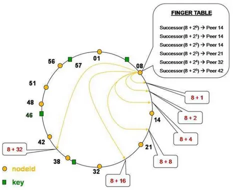
Figure 2-12: Lookup procedure in Chord. ... 63
Figure 2-13: Chord - Construction of the Finger table. ... 64
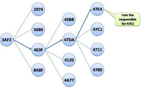
Figure 2-14: Plaxton-like prefix routing... 66
Figure 2-15: Routing in Pastry. ... 69
Figure 2-16: A simplification of the butterfly topology used by Viceroy. ... 78
Figure 2-17: Chord-like mapping of peers and resources in Viceroy. ... 78 Figure 3-1: Chord-like logical ring used by Georoy. ... 84 Figure 3-2: Butterfly topolgy in Georoy. ... 85 Figure 3-3: Division of the geographical area in sub-regions for Georoy's mapping. ... 88 Figure 3-4: Overview of the P2P network.. ... 94 Figure 3-5: Information retrieval procedure in Georoy. ... 101 Figure 3-6: Physical hops in Georoy with resource replication. Grid topology. ... 105 Figure 3-7: Physical hops in Georoy with resource replication. Random topology. ... 106 Figure 3-8: Logical hops in Georoy with resource replication. Grid topology. ... 106 Figure 3-9: Logical hops in Georoy with resource replication. Random topology. ... 107 Figure 3-10: Effect of the blacklist on the number of physical hops for different percentage of unavailability. Grid topology. ... 107
topology. ... 108 Figure 3-12: Effect of the blacklist on the number of logical hops for different percentage of unavailability. Grid topology. ... 108 Figure 3-13: Effect of the blacklist on the number of logical hops for different percentage of unavailability. Random topology. ... 109 Figure 4-1: Scenario overview. ... 114 Figure 4-2: Comparison between the number of logical hops in Georoy and Bamboo in grid topology. ... 123 Figure 4-3: Comparison between the number of physical hops in Georoy and Bamboo in a grid topology. ... 124 Figure 4-4: Comparison between the delay in Georoy and Bamboo in a grid topology. ... 125 Figure 4-5: Comparison between the percentage of lookups completed in Georoy and Bamboo in a grid topology. ... 125 Figure 4-6: Comparison between the stretch factor in Georoy and Bamboo in a grid topology. ... 129
Figure 4-7: Comparison between the number of logical hops in Georoy and Bamboo for random topology. ... 129 Figure 4-8: Comparison between the number of physical hops in Georoy and Bamboo for random topology. ... 130 Figure 4-9: Comparison between the delay in Georoy and Bamboo for random topologies. ... 130 Figure 4-10: Number of logical and physical hops in Bamboo in a grid topology with 225 nodes. ... 132 Figure 4-11: Number of logical and physical hops in Georoy in a grid topology with 225 nodes. ... 132 Figure 4-12: Delay in Georoy and Bamboo in a grid topology with 225 nodes. ... 133 Figure 4-13: Number of logical hops in Georoy in a grid topology exploiting resource replication. ... 134 Figure 4-14: Number of physical hops in Georoy in a grid topology exploiting resource replication. ... 134 Figure 4-15: DTN statistics in Bamboo. ... 136 Figure 4-16: DTN statistics in Georoy. ... 136
Figure 4-18: CDF of intercontact time for different data mule's velocity. ... 138 Figure 4-19: Replication effectiveness in resource downloading for Georoy... 139
1
Abstract
Abstract
The success of experiences such as Seattle and Houston Wireless has attracted the attention on the so called wireless mesh community networks (WMCNs). These are self managing wireless networks in which each node acts as a router able to forward data flows towards the designated destination directly or via multi hop paths. WMNs, whose success is due to their capability in building cost effective and highly scalable wireless networks, are spontaneously deployed by users willing to share communication resources as well as multimedia contents. Become popular since the introduction of cheap wireless technologies such as IEEE 802.11, WMCNs represent a promising framework aiming at reducing the digital divide between town and countryside and, consequently, promoting social communication and business advancements in rural areas.
Peer-to-Peer networks, due to their capacity of providing a good substrate for large scale content-resources sharing and distribution applications, represent an interesting and promiscuous research area of the ICT and could play a key role in the diffusion
of mesh paradigm meeting the growing need of communication and resource sharing among people anywhere and anytime.
Extending the P2P paradigm to wireless networks presents several difficulties due to their dynamic, multi hop and often power and computational constrained nature. While ad hoc and sensor networks represent very challenging environment due to, respectively, the high mobility and the power-computational constrains, for wireless mesh there are not so many restrictions. Nevertheless, some considerations must be taken into consideration. We provide some fundamental guidelines in designing P2P overlay schemes for WMCNs reaching the conclusion that a hierarchical, structured, and distributed-hash-table (DHT) based architecture, exploiting location-awareness, could represent a suitable solution able to guarantee high resilience, fault tolerance, flexibility and scalability, at the cost of supporting a moderate overhead for overlay and nodes' churning management.
According to this idea, we studied and evaluated a location-aware DHT-based P2P scheme, called Georoy. We also introduced some improvements allowing its applicability to wireless mesh networks and opportunistic rural scenarios.
Keywords: wireless mesh community networks, opportunistic networking, peer-to-peer overlay, information retrieval, location-awareness, distributed hash table, lookup performance.
3
Background
1 Background
In this chapter we will introduce some fundamental concepts representing the know-how of the dissertation.
1.1 Wireless Mesh Networks
Before discussing about the wireless mesh networks paradigm, we need introduce the concept of mobile ad hoc network (MANET). It consists of wireless nodes connected together over a wireless medium and able to freely and dynamically self-organize into arbitrary topologies allowing users and devices to communicate without any preexisting communication infrastructure. This concept is not new but it is remained circumscribed to a few of niche sectors such as tactical networks employed essentially for military or specialized civilian applications (disaster recovery, rescue missions, etc.). The requirements for this kind of applications are far from the real users’ requirements. Indeed, military and civilian specialized applications require lack of infrastructure, instant and self-organizing deployment, high fault tolerance, high resiliency, QoS,
security and so on. They are tailored for specialized uses and their cost rather is a crucial issue. On the other hand, the above cited approach is far from the general porpoise scenario the ordinary user is interested to, the latter consisting of a limited number of users/devices willing to share some information, computational/storage resources, or access to the Internet. In this case the lack of infrastructure is not a must and the focus in more specifically on a more pragmatic “opportunistic ad hoc networking” [8] in which multi hop ad hoc networks are not isolate self-configuring networks, but represent a flexible and low cost extension of wired infrastructure networks able to guarantee interconnection among the wireless devices as well as the Internet access. This networking paradigm is the conceptual base of the wireless MESH networks (WMNs).
1.1.1 Network architecture
As shown in Figure 1-1, WMNs are built on a mix of fixed and mobile nodes interconnected via wireless links to form a multi-hop wireless networks usually providing access to the Internet by means of gateways physically connected to the wired Internet backbone. WMNs consist of two types of nodes: mesh routers and mesh clients. Mesh routers have minimal mobility and do not suffer from power constrains; they are equipped with more than one wireless interfaces in order to provide MESH access to the clients
5
Background
and forwarding data packets from source to destination or towards the Internet in a multi hop manner. The integration with other networks such as Internet, cellular, IEEE 802.16, sensor networks, etc., can be achieved through the gateway and bridging functions implemented in the mesh routers. Mesh clients are mobile or stationary devices that that can form a client mesh network among themselves and with mesh routers. Mesh clients are usually more simple devices built based on general porpoise computer, notebook, smartphone systems instead, mesh routers, are built based on dedicated computer systems.
Figure 1-1: Wireless Mesh Network architecture [7].
Notwithstanding this routers and clients are usually built based on similar hardware platforms: clients have necessary functions for mesh networking and, thus, can also work as a router. However they do not implement gateway and bridge functions.
Akyildiz et al. in [7] classify the architecture of WMNs into three main groups:
1. Infrastructure/Backbone: consists of mesh routers forming an infrastructure, well known as backbone, for clients that connect to them. The routers form a mesh of self-configuring and self-organizing wireless links among themselves. Routers also implement gateway/bridge functionalities thanks to which it is possible connecting the mesh net to other kinds of network such as cellular, WiMAX, and above all the wired Internet backbone. This kind of architecture is the most successful one and it represents the technological base for deploying wireless rural community and neighborhood networks. Internet access, contents and resources sharing among participants are the killer applications of this network paradigm. 2. Client WMNs: client meshing provides peer-to-peer
connectivity among mesh clients. In this type of architecture clients build the network by means of self-organizing links among themselves. Client devices must be able to route data packets towards the designated destination also exploiting multi hop path between source and destination of an end-to-end communication. Thus, client devices must implement additional functions such as routing and self-organization.
7
Background
3. Hybrid WMNs: this architecture comprises both the two above mentioned paradigm. Mesh clients can communicate each other by means of the client mesh they build; furthermore they are also able to gain connectivity towards other networks such as Internet, WiMAX, cellular, etc, thanks to the infrastructure network made up of mesh routers including gateway/bridge functionalities. This approach is the same shown in Figure 1-1.
1.1.2 Mesh benefits and criticalities.
WMNs success is due to their capability in building cost effective and highly scalable wireless networks, representing a solution for the easy and fast deployment of connectivity architecture and ubiquitous Internet access. Summarizing, we can highlight the following peculiarity that characterize wireless mesh:
Cheap and fast installation procedures. Currently, the most popular solution to offer Internet connectivity in outdoor environment consists in deploying the so called hot spot. The latter are essentially wireless access point exploiting the IEEE 802.11 standard and are designed to provide a limited number of user devices with connectivity, moreover at very short distances. Such architecture can be extended only introducing a sufficient number of access points directly connected to the wired backbone; in the
light of this, it appears clear that this kind of architecture is not fast and cheap deployable. On the other side, mesh architecture guarantee connectivity to a great number of devices and is able to gain Internet access using only a limited number of mesh routers directly connected to the wired backbone. In such a way it represents a cost effective and fast-deployable solution to offer communication possibilities in a vast range of situations and scenarios.
Large scale deployment. Because of the possibility to exploit multi hop path from a source to a destination node, mesh networks can cover vast outdoor environment; furthermore, taking advantage of fixed powered wireless routers they can implement sophisticated transmission techniques improving the transmission data rate and the wireless links covering distance respect with the conventional, usually power constrained, WLAN technologies involved in wireless ad hoc networks.
Reliability. WMNs guarantee multi hop connectivity between end users using hop-by-hop forwarding towards the destination. Using this approach multiple paths can be detected between two nodes involved in a communication so WMNs exhibit high resilience and fault tolerance against node and link failures.
9
Background
Self-configuring and management. Exploiting a peer-to-peer paradigm to build the wireless distributed system means taking advantage of all the features of this kind of architecture, essentially self-configuration, self-management and, consequently, the capability to effectively react to system changes (e.g., nodes joining or leaving the network) and failures (due to power constrains, radio interference, obstacles between antennas, etc.). These features makes WMNs fast and simply deployable.
What above cited is not an exhaustive list of benefits characterizing the wireless mesh technology but want to provide some key factors that permit to justify because this architecture represents a promising research and application field in the information and communication technology area.
Despite all the benefits illustrated, WMNs are a challenging environment because of several aspects that it need take into consideration during the network design:
· Obstacle to scalability. wireless mesh are based on multi-hop communication among nodes in order to connect source and destination. There are several research papers asserting that multi-hop environments suffers from scalability issues, i.e., when the size of network increases the network performances decreases significantly; transport protocols may loose connection, routing protocols are not able to establish paths between source
and destination node, and MAC protocols may experience significant throughput degradation, unfairness and starvation. Centralized medium multiple access control protocols such as TDMA or CDMA, due to their general requirements such as time synchronization or code management, are difficult to implement in a decentralized structure.
· Criticality of QoS management. WMNs are distributed communication architectures thus guarantying QoS parameters represents a very challenging issue considering that, in addition to end-to-end transmission delay and fairness, more performance metrics such as delay jitter, aggregate and per-node throughput, packet loss rate, etc., must be taken into consideration by communication protocols.
· Security. Security represents a key factor for the adoption of a network technology rather than another. In particular, WMNs suffer from security problems commons to all the other wireless and distributed technologies. In a wireless environment each node can listen the communication of each other if it is in its coverage area. so, it is indispensable introducing efficient schemes able to guarantee security and privacy in data transmissions. Although many algorithms have been proposed for wireless LANs, they are still not ready for WMNs due to
11
Background
the lack of a centralized trusted authority able to distribute a public key in a WMN. On the other side, the existing security schemes proposed for ad hoc networks could be adopted for WMNs, but they are still not mature enough to be practically implemented. Nevertheless, several solutions have been introduced to improve this critical aspect such as secure and anonymous routing (e.g. ANODR and Secure Routing Protocol), secure MAC, etc. · Capacity of WMNs. The study of the capacity of a WMN
represents a very hard challenge to be solved. There are too many factors influencing it such as network topology, traffic pattern, node density, number of radio and or channel employed, transmission power level, node mobility, physical channel modeling, radio interferences, and so on. Under this perspective it appears clear that understanding all the relationship between network capacity and the above factors is a task that unlikely will be concluded exhaustively.
1.1.3 Application Scenarios
Research and development efforts in wireless mesh technology are due to the several applications for which it represents a promising and effective networking solution. In the following we will present some of these application scenarios.
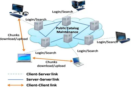
Public Internet access and community networking. Nowadays the most popular architecture for network access is based on cable or DSL connected to the Internet. Only the last-hop is performed using wireless technologies, and in particular the IEEE 802.11 standard. Exploiting this approach, where each home have to use an individual connection towards the Internet, presents several drawbacks:
· Even if the information concerns the community it has to be sent and received through Internet;
· The access to the Internet is expensive and not fast deployable;
· Vast areas of the community are not covered by wireless services;
· Each home has only one available path to access the public network, so the architecture suffers from single points of failure issue;
· Many interesting applications such as computational- storage-data resources sharing among the community members are not available.
13
Background
Figure 1-2: Broadband Internet access and community networking [8].
WMNs enhance this kind of architecture providing users with a cheap, fast deployable, resilient and fault tolerant network where they can both access the Internet and share resources in a P2P manner. On the base of the above considerations it appears clear that WMNs represent the ideal solution to solve the digital divide issue between town and countryside providing an excellent framework for delivering broadband services to such areas. Indeed, the necessity of connecting to the wired backhaul network only a little part of the mesh routers permits a cost effective deployment even with a limited number of subscribers, as found in rural or scarcely populated urban areas.
Spontaneous networking and P2P communications. There are several circumstances requiring a fast deployable, effective and fault tolerant communication architecture. This aspect is
particularly relevant if we think to the public safety: the 9/11 events and the consequently war against terrorism as well as the recent natural disasters have created an urgent demand for wireless network connectivity allowing fast, simple and high bandwidth communications for military and police forces, rescue services, fire brigades, medical corps, etc. Solutions based on cellular technologies, even though they guarantee near ubiquitous coverage and high-mobility speeds, present several drawbacks: the network infrastructure is not always available, (e.g., in facing up to natural disasters the cellular infrastructure can be damaged and only partially available); deploying an ad hoc cellular architecture is very expensive and it does not represent a viable solution in tactical and military operations; guaranteed data rate is often limited, even lower than a dialup connection, so it is not suitable for image, voice and video transmissions. Vice versa, mesh networks successfully address the spontaneous (emergency, disaster recovery, tactical) networking issues offering an effective, scalable, easily deployable solution.
Among the spontaneous networks we can also mention P2P communications. For a group of people holding devices with wireless networking capabilities, e.g. laptops, PDAs, tablets, smartphones, etc, P2P communications anytime and anywhere represent a must. For their characteristics WMNs are able to meet this demand in a very simple and cheap manner.
15
Background
Enterprise networking. Under this paradigm we can consider small (office case) and medium (the case of offices in a building) size as well as large scale (the case of offices in multiple buildings) networks. Currently, standard IEEE 802.11 wireless networks are widely used in various offices but, if this architecture could result effective for small size office or enterprise, it results inadequate for medium to large scale enterprises or offices. Standard 802.11 access points need to be directly connected to the wired LAN for providing Internet access and guarantying end-to-end communication among users of the same enterprise belonging to different offices each far from the other. If the access points are replaced by mesh routers Ethernet wires can be eliminated and multiple backhaul access modems can be shared by all terminals of the network, improving resilience, fault tolerance and resource utilization. Furthermore, mesh nets can adapt easily as the size of enterprise expands. Obviously, the service model above illustrated can be applied to many other public and commercial service networking scenarios such as airports, hotels, hospitals and medical centers, shopping centers, and so on.
Transportation systems. WMNs are a viable solution for meeting two important demands related to transportation systems:
· Realizing intelligent transportation systems, i.e. integrated public transportation systems built to be safe, efficient and secure. Wireless mesh represent a flexible solution to
realize the information delivery system necessary to control and manage transportation services. WMNs allow driver communications, remote monitoring of in-vehicle security video, information about traffic congestions, pollution control, service awareness for passengers.
· Providing passengers with Internet connectivity. Often Internet access is limited to stations and stops thanks to 802.11 technology, but it should be useful introduce this capability also during the travel. Also in this case mesh technology offers a suitable solution able to guarantee this kind of service. Obviously, a mesh architecture for this porpoise needs two key techniques: a high-speed mobile backhaul from a vehicle (car, bus, train, etc.) to the Internet and mobile mesh networks within the vehicle.
1.1.4 Standards on Wireless Mesh Networks.
Actually, wireless technology is most popular in one hop network architectures. Typically, it is used to provide Internet access to fixed or mobile devices equipped with compliant wireless cards and connected to a wireless access point. The IEEE 802.11 standards and the WiFi Alliance played a key role in the success of this kind of architecture but a lot of efforts must be addressed in the field of mesh networking. 802.11 a/b/g/n can be used in ad hoc manner but it presents several drawbacks in multi hop connectivity,
17
Background
as explained above, thus we can consider it far from to be a suitable solution for mesh networking. The lack of a well established standard and the growing interest in wireless mesh applications has boosted industrial efforts to develop proprietary solutions to make WMNs a reality. Some vendors initially focused on products based on IEEE 802.11 technologies coupled with proprietary software solutions making these systems incompatible one with other. Several other vendors adopted solutions based on proprietary radio technologies considering the 802.11 standards not adapted for this kind of approach.
In despite of this, open standards are essential for industry and for a wide deployment of a technology because they enable economies of scale, which bring down the cost of equipment and ensure interoperability. For these reasons several IEEE standard groups are actively working to define specifications for wireless mesh networking. Because of the complexity of the problem different task groups have been created to define the requirements and provide the related solutions for the different mesh networking architectures. In the following sections we will present the results of these efforts in the different areas of interest: wireless personal area network (WPAN), wireless local area network (WLAN) and wireless metropolitan area networks (WMAN).
1.1.4.1 IEEE 802.15.5
Wireless personal area networks (WPANs) are a very interesting solution for home, office and wireless sensor networks. WPANs are characterized by short distance among nodes and low power consumption. On these requirements focuses the activity of standard groups such as IEEE 802.15, Bluetooth Special Interest Group (SIG), WiMedia Forum, UWB Forum and so on.
In particular, we will focus on the IEEE 802.15 standard family that contains many task group covering almost all scenarios where WPANs are involved. It follows a brief description of the different standards:
· 802.15.1: studies PHY and MAC specifications for wireless connectivity of fixed, portable and mobile devices belonging to the so called personal operating space (POS), that is, a space enveloping the person and extending up to 10 m in all directions. It is based on Bluetooth technology and, according to this, it works in the 2.4 GHz ISM frequency.
· 802.15.2: because the previous standard operates in the same 2.4 GHz band of 802.11 products, the work of this new task group focused on specifying the coexistence mechanisms between wireless PAN and LAN and other networks working in the same unlicensed frequency range.
19
Background
· 802.15.3: this task group was created to specify a new MAC and PHY for WPANs able to support high rate applications such as digital imaging and multimedia achieving scalable data rate from 11 Mbps to 55 Mbps. This working group originated two different amendments, “a” and “b”: the former focused on correcting and revising the basic 802.15.3 standard, the latter focused on increasing the transmission data rate developing ultra wide band (UWB) based wireless PAN in order to support high rate multimedia traffic. The activity of group “a” was withdrawn but the researches on this field has never stopped thanks to the efforts of two industrial consortiums called WiMedia Forum and UWB Forum.
· 802.15.4: this standard defines PHY and MAC layers for low rate wireless PANs. Regarding the former, two types are specified: 868/915 MHz direct sequence spread spectrum (DSSS) and 2450 MHz DSSS, the first achieving a data rate equal to 20/40 Kbps and the second a data rate up to 250 Kbps. MAC layer adopts a CSMA/CA approach, in both star and peer-to-peer topologies.
In all the above mentioned standards mesh topologies are not considered. Extending WPANs with mesh capabilities is the focus of 802.15.5 task group. The latter aims to provide a recommended practice rather than a mandatory standard for defining an
architectural framework allowing WPAN devices to be interoperable in a stable and scalable wireless mesh topology.
In 802.15.5 we can distinguish three types of PAN device: PAN coordinator, coordinator, and end device. End devices are connected to the related coordinator forming a star topology as that employed in other 802.15 PANs while coordinators are connected to each other through a mesh topology. Defining the latter means, above all, redesigning the MAC sublayer and this is the major effort of 802.15.5 standard group. While other 802.15 standards only focus on PHY and MAC without any remark on the routing procedures, specifying a routing protocol is one of the most important tasks for the 802.15.5 task group. In particular, the MAC has been enhanced based on that of other WPANs and new routing function has been added on top of the enhanced MAC protocol. The introduction of routing capabilities is a key feature to guarantee the interoperability of products belonging to different vendors. Since, as mentioned above, WPANs address both low rate and high rate wireless networks having different PHY and MAC sublayers, the 802.15.5 task group is currently working on separate specifications for them. However, the protocol stack of these two types of network is the same and the proposed routing capabilities are based on the meshed tree approach.
21
Background
Figure 1-3: 802.15.5 meshed wireless PANs (adapted from [10]).
The tree defined in the proposal is called adaptive robust tree (ART) and is shown in Figure 1-4. Three phases are defined in ART:
· Initialization: during this phase, nodes joining the network build the ART tree. Logical addresses are adaptively assigned during the tree formation procedure to reflect the actual network topology; furthermore each node keeps an ART table (ARTT) to track its branches and, to each branches is assigned one or more blocks of consecutive addresses. In particular, the ART tree formation is divided into two steps: association and address assigning. During the first one, beginning from the root, nodes gradually join the network forming the tree.
But this is not sufficient to make the tree an ART. To address this, it needs that each node has a logical identifier. After the tree reaches its bottom, a down-top procedure begins in order to calculate the number of nodes for each branch, as illustrated in Figure 1-4. When the procedure ends, each node of the tree can indicate a desirable number of addresses.
· Operation: new nodes are still allowed to join the network and, for each substantial change of either the number of nodes or the network topology, the tree need to be reconfigured.
· Recovery: when the tree is broken then the recovery procedure is triggered, involving only the affected part of the tree. The ART is constructed in such a way that tree repair and recovery can be accomplished without changing any assigned identifier.
23
Background
Figure 1-4: Calculation of number of nodes along each branch [66].
By exploiting this procedure, it is possible to build a meshed ART (MART) on top of an ART. This is realized by using additional links (shown in Figure 1-5 as magenta lines) in such a way that the network looks more like a mesh than a tree even if from each node’s point of view the network is still a tree. By forming a MART it is possible to both route packets through shorter paths and remove single points of failure.
1.1.4.2 IEEE 802.11s
The IEEE 802.11 [67] family is currently the most popular and successful wireless networking standard for wireless LANs. It define the physical layer and MAC sublayer for the devices used in WLAN networking. IEEE 802.11 a/b/g/n are based on a structure consisting of a device called Access Point (AP) to which end user devices or stations (STAs) connect for accessing network services. The set of STAs managed by the related AP is called basic service set (BSS). Furthermore, the above mentioned standards also permit another kind of networking: the independent basic service set (IBSS), well known as ad hoc network, where each device can communicate with others without APs. A set of BSS, interconnected by a distribution system (DS), usually realized by wired technology, forms an extended service set (ESS). Under this perspective, we cannot define this architecture because the distribution system is generally a wired LAN. The IEEE 802.11
25
Background
family continue to advance with the introduction of various amendments but they are still limited because of their dependency upon the wired technology to constitute the distribution system. Using 802.11 as mesh technology can be a solution (e.g., we can consider a mesh network realized using 802.11 b/g/n as one hop access networks coupled with 802.11 a in ad hoc mode for realizing the multi hop mesh backbone) but 802.11 standards primarily aim at fulfilling one-hop communication needs and, as a consequence of this design choice, they are affected by the problems of throughput degradation, unfairness and starvation when applied in multi hop architectures. With the aim of solve this problem and obtain an effective solution for wireless distribution systems (WDS), a separate TG called IEEE 802.11s was formed in May 2004.
The activity of 802.11s TG focuses on the specification of a new protocol suite for the installation, configuration and management of WLAN mesh. Its implementation is based on the PHY layer of 802.11 a/b/g/n operating in the unlicensed 2.4-5 GHz frequency bands, introducing the major novelties in the MAC sublayer design.
Figure 1-6: IEEE 802.11s network architecture [9].
In particular, MAC 802.11s will introduce a path selection protocol for routing data in the mesh topology instead of the routing protocol. The proposed architecture is depicted in Figure 1-7 regarding which we can provide the following definitions:
· Mesh Point (MP): device that support mesh-relay functions including neighbor discovery, channel selection, association with neighbors;
· Wireless Distribution System (WDS): is the set of MPs and the related wireless links they form;
· Mesh Access Point (MAP): is a specific mesh node that include the capabilities of an access point thanks to which other 802.11 compliant devices can be connected to the mesh network. Usually it implements 802.11s as mesh standard to join the mesh and 802.11 b/g/n to play the role
27
Background
of access point providing connectivity to other legacy user terminals:
· Mesh Portal Point (MPP): is the more complex device including all the capabilities of a mesh point but providing connectivity towards other meshes or access to the Internet: it acts as a gateway towards the external network technologies.
Figure 1-7: Architecture of MAC 802.11s [9].
The most important novelties involving the MAC design are illustrated in Figure 1-7 and they include:
· Topology learning; · Routing and forwarding;
· Medium access coordination in the distributed architecture;
· Mesh configuration and management; · Mesh measurements;
· Security functions.
1.1.4.3 IEEE 802.16 mesh mode
The IEEE 802.16 [68] working group defines the physical layer and the MAC sublayer standards for wireless metropolitan area networks (WMANs). This standard, associated with Worldwide Interoperability for Microwave Access (WiMAX), was designed to operate in the licensed 10-66 GHz frequency range requiring line-of-sight (LOS) towers, called base stations (BSs), covering up to 5 Km, using an architecture similar to that employed in the cellular networks. It was defined to meet the need for a backhaul network for the broadband wireless access at much lower cost compared with the wired counterparts, such as DSL and cable. The standard was initially created for point-to-multipoint architecture aimed to provide higher data rate (up to 75 Mb/s) for each subscriber station (SS). Basic standard was expanded creating several task groups, from “a” to “g”, to address:
· a: addition of mesh capabilities;
· b: providing quality of service (QoS) feature; · c: supporting interoperability;
29
Background
· e: supporting mobility;
· f: supporting multi hop capabilities in standard e; · g: providing efficient handover and QoS.
Figure 1-8: IEEE 802.16 in (a) PMP mode and (b) mesh mode [9].
The IEEE 802.16a standard adds the mesh mode to the PMP defined in IEEE 802.16.the new standard operates in the licensed and unlicensed frequencies of 2-11 GHz that allows non-line-of-sight (NLOS) communications, obtaining a coverage area of 50 Km. While in the PMP each SS must be connected to a BS, in mesh mode a SS can communicate directly with each other without the need of a BS. Thus, a SS in mesh mode serves as a router able to forwarding the data traffic originated by a neighbor towards the target BS that connects the mesh to other external networks.
Active nodes belonging to the mesh network send periodically MSH-NCGF (mesh network configuration) messages exploited by new nodes wanting to join the mesh for synchronizing with the
existing network. A new node actively scans to hear the MSH-NCFG messages and, once received one or more, it establishes synchronization and initiates the entry procedure sending a MSH-NENT (mesh network entry) message. After authorization, it receives a 16-bit node identifier from the mesh BS.
Medium access is based on two types of TDMA scheduling mechanisms:
· centralized scheduling: the BS manages the communication resources for all SSs within a certain hop range;
· distributed scheduling: all nodes coordinate with each other for accessing the channel, including the mesh BS.
1.2 Opportunistic Networking
An opportunistic network [12] is a type of challenged network where intermittent network contacts are met and link performance are variable and unstable. In general in these networks stable end-to-end paths do not exist since nodes can be isolated most of the time and paths may frequently break up. To cope with these problems while supporting communications, a store/carry-forward approach can be used where intermediate nodes keep the message while the connectivity is down. This requires that applications are delay-tolerant [58]. Moreover, the use of an opportunistic paradigm
31
Background
allows to foresee a process of resource propagation during occasional intercontacts between nodes.
ZebraNet [13] is an example of DTN networking, which tracks animal movements across a wide area. Collars carried by animals work like peer-to-peer devices which communicate to deliver logged data to monitoring centers. Opportunistic networking is also dealt with in an analytical perspective in the Pocket Switched networks [14] where intercontact times among pairs of nodes are analyzed in real human mobility scenarios. Similar studies aimed at characterization of social interactions have been also carried out at MIT in the context of the reality mining project [15]. Also the Haggle project [16] proposed a networking architecture along with a set of protocols and description languages to enable communication in intermittent network connectivity scenarios.
Concerning the network layer, two routing approaches are common in opportunistic scenarios: forwarding and flooding. In forwarding, intermediate nodes relay a single copy of the packet over several hops towards the final destination. The difference among the various forwarding approaches relies in the methodology used for selecting the best path for forwarding data: direct-transmission [17, 18], location-based transmission [19, 20] or using an estimation based approach [21, 22]. The forwarding approach has typically low overhead in terms of packets circulating in the network but can suffer for low packet delivery ratio and long delivery delays. On the contrary, the flooding based schemes are
more robust but can add significant overhead into the network by having multiple copies of a packet traversing the network.
In opportunistic networks, a connection-oriented transport layer protocol such as TCP requires reengineering due to frequent disruptions and intermittent end-to-end connectivity. For example, the Licklider Transmission Protocol (LTP) and its evolutions have been introduced in order to cope with retransmissions in high latency environments such as the challenged ones. Typically, a new protocol layer is required to be identified and located in between the application and transport layers. This protocol, denoted as bundle layer [23, 24], allows each node to act as both a router or a gateway to transfer messages across different regions. In this way the problem of supporting traditional applications where the end-to-end source-destination connections do not exist can be overcome. At the Bundle layer, functionalities of storing/carrying- forwarding are considered and employed for multicast and anycast [25–27].
Finally, concerning the application layer, support for traditional applications such as Web and email is not possible since the underlying transport protocols do not work properly in challenged opportunistic environments. As a consequence, in [28] the use of SMTP proxies is introduced to hide disruptions among users. Emails are thus sent in bundles into the opportunistic network and carried to a mail gateway which forwards and receives the mail between the infrastructured and the opportunistic networks. In [29], an Internet proxy is used to collect search
33
Background
engines and prefetch web pages. The user query is stored until the mobile node will contact the proxy after a disruption.
1.2.1 Opportunistic networks for developing areas
The success of experiences such as Seattle and Houston Wireless has attracted the attention on the so called wireless mesh community networks (WMCNs). These, become popular since the introduction of cheap wireless technologies such as IEEE 802.11, are spontaneously deployed by users willing to share communication resources (usually to obtain an adequate Internet access) as well as other resources such as data, news, images, music, movies and so on. WMCNs represent a promising framework aiming at reducing the digital divide between town and countryside, which degrades both social communication and business advancements in rural areas.
Opportunistic paradigm becomes critical in challenging scenarios like rural communications in emerging countries like India or Africa, where the lack of an infrastructure makes communications almost impossible. Opportunistic and Delay-tolerant (DTN) communications are thus the natural choice for a networking paradigm where nodes can be disconnected from the Internet for the majority of the time and exchange of data can take very long time.
In emerging countries numerous projects aimed at rural poverty alleviation have been proposed. For example the Sustainable Access in Rural India (SARI) program [56], inaugurated in 2001, consists of disseminating more than 80 rural Internet kiosks distributed in the Madurai area of Tamil Nadu in India. However, not all villages can be served by these kiosks and thus, in parallel, exploiting an opportunistic approach, the Computers on Wheels (COW) project [57] has been carried out in India as well since 2003. In this case, a set of motorcycles equipped with an Internet-connected laptop travel between very remote villages to collect requests for Internet access and support users’ communications during the limited time the motorcycle stops at the village.
35
P2P overlay networks
2 P2P overlay networks
Peer-to-peer networks represent an interesting and promiscuous research area of the so called information and communication technology. This interest is due to their capacity of providing a good substrate for large scale data/content/resources sharing and distribution applications.
There are several works in the field so, the aim of this chapter is providing a classification and a brief description of the most important scheme proposed in the recent years.
For the sake of simplicity we can say that a P2P network is made up of nodes, called peers, that - differently from the client-server paradigm - play symmetric roles in the architecture. They form a self-organizing overlay network overlayed on the network protocol and offering a set of features useful for the applications running over it.
Nodes joining a P2P network can be deployed in a local area or in a wide area. Although they can communicate with each other by means of the network protocol, i.e. the Internet Protocol, this is not sufficient for realizing a P2P architecture. This latter needs the definition of procedures for managing peers and resources, routing the requests for contents, guarantying security, reliability, fault
resiliency and trustworthiness. This is the scope of the overlay network according to which:
· peers joining the network are organized in a graph that can be unstructured or structured, centralized or decentralized; · peers can look for contents shared by the other peers
sending a lookup query message through the network; · lookup query messages and related replies can be routed
towards the destination, i.e. the peer that hold the resource.
In [4] authors propose an abstract P2P overlay network architecture consisting of 5 levels:
· network communications layer: describes the network characteristics of the terminals connected. A P2P network can be made up of personal computers connected by Internet, wireless terminals or sensor devices connected in ad-hoc manner;
· overlay nodes management layer: this refers to the procedures necessary for building the overlay structure, managing nodes’ joining/leaving actions, managing the shared resources, defining and keeping update the routing table for each peer, routing the lookup query requests and replies;
37
P2P overlay networks
· features management layer: deals with the security, reliability, fault resiliency, trustworthiness and content replication aspects;
· services-specific layer: represents an intermediate level between application tools and the underlying P2P architecture supporting the application-specific components;
· application level layer: consisting of tools, applications and services that are implemented on top of the underlying P2P overlay network.
Figure 2-1: the difference between network and overlay layer.
We can classify the overlay network schemes into two great family of algorithms on the base of the organization of the graph: Unstructured and Structured.
Unstructured. peers are organized in a random manner, the graph has not an ordered structure and resources storage and management don’t follow any rule. Each peer can manage
IP Overlay IP IP Overlay Overlay ?
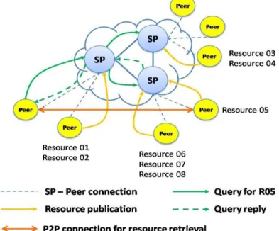
whatever content. The random graph, resulting from the building of the network, is generally organized or in a flat or in a hierarchical manner. In flat organizations each node has the same role in building and managing the overlay. In hierarchical case, usually, we can distinguish two types of nodes participating the network: peers and super peers. The former represent nodes that want to share contents or resources, the latter instead play a key role in the building and management of the overlay and provide peers with the procedures necessary to the resource discovery and retrieval.
Figure 2-2: Abstract overview of P2P overlay architecture (adapted from [4]).
Unstructured architectures employ flooding or random walks to forward a lookup query (i.e. a packet sent by a peer wanting to discover and retrieval a resource or a content stored in another peer of the network). It is obvious that a such paradigm is effective and suitable only if resources are very popular among participants to the net and, thus, multiple copies of a certain resource are available.
39
P2P overlay networks
If this is not the case, instead, the lookup procedure necessary to retrieval a content becomes inefficient: lookup query for a rare content has to be sent to a large fraction of peers before reaching the node managing or storing the requested resource. Well known examples of unstructured approaches are: Gnutella [36], Freenet [44], BitTorrent [47], eDonkey2000 [48][49], FastTrack [45], KaZaA [46]. We will discuss them in the following paragraph.
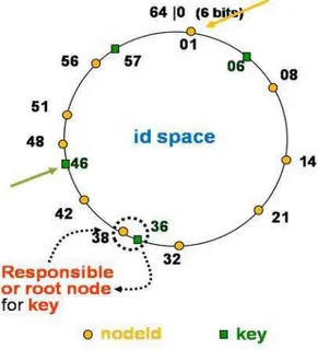
Structured: these architecture are based on the construction of a well defined graph. They also can be classified in flat and hierarchical on the base of the organization of peers participating to the net. Usually, in this kind of approach, peers have a logical ID that permits to identify them within the overlay. IDs are assigned in a logical address space. Shared contents, in a similar way, are associated to a identification key belonging to the same logical space and obtained,
for example, hashing the title of the content. In a structured architecture each resource distributed in the network is managed by a unique responsible peer, usually the peer with the ID closest to the key value of the resource in the logical domain. In this way, when a node want discover or obtain a content it has to:
· hash the name (or other parameter, according to the employed scheme) of the requested content for obtaining the value of related key;
· send a lookup query for the key using the routing scheme adopted by the algorithm. Note that in this case the responsible peer is identifiable by the other peer and it is not necessary any form of flooding or random walk forwarding.
Note that the architecture needs only that peers hold a pointer to the resource they are responsible for; contents are usually stored in other locations. Thus, the reply to a lookup query is generally a pointer to the physical location where the resource is stored. Structured graphs obtained exploiting this approach enable efficient discovery of data items using the given keys. This feature is particularly useful when coped with large-scale networks and shared contents are not widespread. Although their efficiency in locating rare items since the key-based research/routing mechanism, structured algorithms incur in significantly overheads than unstructured ones for popular content. This is the reason
41
P2P overlay networks
because over the internet today the unstructured P2P networks are more commonly used. The most important scheme belonging to this family are: Content Addressable Network (CAN), Tapestry, Chord, Pastry and Viceroy. We will discuss them in the following.
Another classification of the overlay structure can be made on the base of decentralization. We will say that a P2P architecture is decentralized whether the overlay system is distributed. If this is the case each peer participates to the building of the overlay network. Each peer, once received a lookup query, is able to forward it towards the correct destination comparing the value of the requested key with the entries of its routing table. Furthermore, resources are distributed uniformly among the peers and each of them is responsible for a well defined range of logical keys.
In centralized structure there is one or more servers the peers connect to in order to transmit and obtain information. Peers that want share and obtain contents have to contact servers for:
· publish the catalog of the resources they want to share with others members;
· receive information about the resources available within the network;
· receive the network address of peers holding the requested resources in order to download them.
Centralized systems suffer from a common disadvantage: the single point of failure due to the centralized search server. This
aspect obviously dramatically impacts on the system performance in terms of reliability and fault resiliency.
2.1 Unstructured P2P overlay networks
2.1.1 Napster
Napster [35] was the first commercial P2P system introduced in 1999. It pioneered the idea of a centralized overlay structure supporting file search facility. For the first time it introduced the concept at the base of modern file sharing: the distribution of popular contents need not to be sent to a central server from which users can get them; instead it could be handled in a more scalable and effective manner by many peers that have the requested contents. Following this approach users wanting to download data join the P2P network connecting to a central server. Once established the connection they can search if the desired file is available in the public catalog and, if this is the case, server will reply with the address of peers from which it is possible downloading the requested content. The experience of Napster, whose killer application was the mp3 files sharing, ended because of legal issues against the RIAA (Recording Industry Association of America). The lawsuit forced Napster to shut down the file-sharing service of digital music. However the new communication paradigm caught the imagination of platform providers and users
43
P2P overlay networks
alike. Now Napster is again online and employs the original architecture design for commercial distribution of mp3 files.
2.1.2 Gnutella 1 e 2
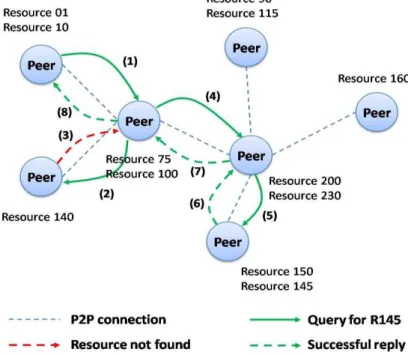
Gnutella was the second major P2P system that appeared after Napster. It consists in a decentralized and unstructured architecture where peers joining the networks form a flat random graph. Each peer works as client and server at the same time. Like client it search for resources shared by others peers, like server it manages the lookup queries sent by the others nodes, answering with a lookup reply message if the researched content is available in the own catalog or forwarding the query message towards its neighbor peers if not.
To locate a data item a peer queries its neighbors and the typical query routing consists in flooding. Because of such design the protocol is extremely resilient to peers churning, i.e. peers joining and leaving the system frequently, and it present a high fault tolerance. But, on the other side, this search mechanism are not scalable generating high overhead when the number of peers grows.
When a node want to join the Gnutella network it has to connect to one of several well known host whose list is available online. Once connected the peer can send the messages to discover other participants and establish TCP connection with them. These
messages are simply flooded in the network. Thus, in such structure, the allowed messages are:
· Group membership messages (PING-PONG): a peer joining the network send a broadcast PING message in order to notify its presence to the other node; the PING message is then forwarded by its neighbors and, at the same time, initiates a back-propagation of PONG messages. The latter are replies to the PING message containing information about the peer such as the IP address, the number of items it holds, etc. ;
· Search messages (lookup query and reply): queries contain the references of the searched contents such as an identification string or a key value. Once received a query message the peer finds in its catalog and, if it is not the responsible peer for the resource, it broadcasts the lookup query towards its neighbors. When the request get the responsible peer it sends a lookup reply, back-propagated, containing the information necessary to download the content.
· File transfer messages (GET and PUSH): when the lookup procedure ends, it is possible to establish a direct connection between the requester and the node holding the resource and file transfer can take place.
45
P2P overlay networks
Scalability problems occur when the number of lookup or the number of peers increases. In such case the efficiency of the protocol is poor and for this reason it was be necessary introducing several improvements [51][52][53] to solve this issue.
Figure 2-4: Gnutella architecture.
The latest versions of the algorithm, called Gnutella 2, uses the concept of hierarchical organization in order to minimize the number of queries flooded within the network. This approach is possible thanks the introduction of Hub or Super Peers [37], i.e. nodes characterized by high bandwidth connectivity, that play a key role in improving routing and information retrieval performances. Exploiting this network paradigm, only the super peer nodes concur in building and managing the overlay structure; they are, also, the only responsible of forwarding the query messages. When a peer, or leaf peer, want to join the network it has
to connect to a super peer and communicate its resources catalog. Likewise, when it want to search a content it sends the query message only to its responsible super peer that broadcast the query message towards its neighbor super peers.
This approach considerably reduces the traffic in the overlay and makes the system much more scalable compared to original Gnutella. Obviously, the complexity of Gnutella 2 is higher than that of the original system and the vulnerability of the system to attacks, resiliency, and fault tolerance increases as well because the super peers represent a single point of failure.
2.1.3 Torrent
BitTorrent is by far the most popular P2P protocol used over the Internet today. It is quite different from all of the systems considered above. It maintains a decentralized structure in resources distribution but, in order to obtain fast and fair download, it employs a centralized search mechanism. When a node want to retrieval a content it has to download the .torrent file making use of central-directory based search facilities; usually web sites serve for this purpose. The .torrent file contains information about the researched file/resource; in particular it reports the name of the file, its size and hashing information and, above all, the URL of the tracker. The latter keeps track of all the peers who have the resource (both partially and completely) and permits to establish
47
P2P overlay networks
TCP connections among the peers interested in downloading the resource. To obtain load balancing in the P2P network, the tracker provides a random list of peers that have the file.
Figure 2-5: BitTorrent architecture.
With the aim of a fast spreading of contents the protocol cuts files into pieces of fixed size (256 Kbytes). Once established TCP connections among the nodes interested in resource sharing, each peer communicates the other with the list of pieces owned. At this point, the process of download/upload can begin. The general way for users is to download the rarest pieces of the file first, leaving the most popular ones for later. When a peer has the complete file it is called seed. In order to avoid the problem of free riders BitTorrent adopts a tit-for-tat policy according to which a peer responds with the same action that its other collaborating peer
performed previously. For the sake of simplicity, we can consider the case of a peer that downloading the pieces of a file does not contribute to the spreading of this resource reducing its upload rate: collaborating peers can use choking, that is a temporary refusal to upload towards the misbehaving node.
BitTorrent network is a very effective solution but suffers from legal issues (its killer application is the sharing of contents protected by copyright as video, music, software and games) and it shows several problems in finding and downloading old or unpopular contents because of the difficulties in creating the swarm of exchanging nodes interested in the sharing of these resources.
2.1.4 Edonkey
The eDonkey P2P system is one of the most successful and popular file sharing system. The Internet studies proposed in [69] show that the Internet traffic due to eDonkey is second only to BitTorrent protocol. Its most famous client is by far eMule, that have today more than 4 million users connected online.
The eDonkey search procedure follows the client/server architecture, where servers index the contents their clients provide. Note that servers only store information about the resources, but not the resources themselves.
49
P2P overlay networks
1. Server-server: these communications performed over UDP connections are used by servers to maintain updated the list of other known servers and to forward the requests for contents (it is possible, in fact, to choice if a content research should be performed locally, i.e. among the peers managed by the server, or at whole network, i.e. extended to the peers managed by the other servers);
2. Client-server: performed via TCP connections are necessary for: (i) logging in a node that want join the network; (ii) communicating the catalog of resources the node want to share with the other peers; (iii) sending query messages to locate contents.
3. Clint-client: established to download/upload contents among peers.
When a node want to join the network it has to login onto a server via TCP by providing its IP address, the connection port and a list of files/resources it want to share. The list of servers, with the related addresses, is usually provided into the client or available via dedicated web sites. Once established the connection, server assigns a user ID to the node and update its local database adding the resources catalog of the latter. After this exchange of information the node is free to search and download files shared by other peers and, meanwhile, his files can be uploaded by other participants. The search procedure uses simple text search to locate files. As soon as the desired file is located user sends a query
sources message containing the hash (MD4 algorithm) of the file to its responsible server; the server answers with ID/port pairs of the clients that claim to store the file. At this point client-to-client connections start to transfer file. With the aim of making fast the retrieval procedure, eDonkey uses the multiple sources downloading strategy that consist in separating files in multiple pieces, called chunks, typically of 10 MB each, that can be transferred separately to parallelize the procedure downloading chunks from multiple peers simultaneously.
Figure 2-6: eDonkey P2P network.
The eDonkey protocol also avoids the problem of free riders by introducing a complex scoring mechanism that rewards collaborating nodes and penalizes peers active only in download.
![Figure 1-1: Wireless Mesh Network architecture [7].](https://thumb-eu.123doks.com/thumbv2/123dokorg/4521321.34928/15.892.237.700.583.830/figure-wireless-mesh-network-architecture.webp)
![Figure 1-3: 802.15.5 meshed wireless PANs (adapted from [10]).](https://thumb-eu.123doks.com/thumbv2/123dokorg/4521321.34928/31.892.262.679.273.555/figure-meshed-wireless-pans-adapted.webp)