i
Abstract
Residual stresses in the PVD-coatings usually deteriorate the adhesion of coatings and adversely affect the performance of coated components. Nonetheless, it might have some positive effects such as resistance to crack nucleation and propagation, as well as wear and fatigue failures. A proper control of residual stress always remains essential for successful coating development. Multilayer systems with alternate hard (ceramic) and soft (metallic) layers compared with a monolayer, usually offer a much more ease to control the residual stresses, improve adhesion, increase overall thickness and produce the toughening response. However, in order to control the residual stresses, it is always important to find the optimal thickness of individual layers. An increase in metallic layer thickness significantly relieves the residual stress in ceramic layer. However, the performance of multilayer systems could be affected. Alternatively, an increase in thickness of ceramic layer close to the substrate could mostly increase the residual stress level. Hence the thickness of individual layers remains a key factor for the optimal performance of multilayer coating systems.
In the present work, finite element analysis (FEA) of residual stress coupled with ANSYS optimization algorithm was used to develop stress-optimized Ti-TiN multilayer coatings. Thickness of individual layer was optimized for the coating configuration comprising of six-layer while taking into account the thermal as well as thickness dependent intrinsic residual stresses.
Multilayer coatings corresponding to those of FEM stress-optimization were experimentally produced in comparison with bilayer using magnetron sputtering physical vapour deposition system. The nanoindentation hardness and elastic modulus of multilayer coatings in comparison with bilayer was investigated for the assessment of deterioration in stiffness taken place by the incorporation of Ti (titanium) interlayers. Further, investigations of the stress-optimized multilayer configurations were performed for the influence on in-plane residual stress and practical scratch-adhesion. Analytical description of the failure mode under scratch adhesion testing was demonstrated for an accurate measurement of practical adhesion of coatings to the stainless steel
ii
substrate. Finally, the scratch adhesion, nanoindentation and experimental in-plane residual stresses results clearly demonstrated the significance of preliminary stress-optimization measures for the development of Ti-TiN multilayer wear-resistance coating systems.
The dissertation consists of six chapters. Chapter 1 is about the introduction in which Gap of knowledge, significance of the investigation and objective, approach and scope of investigation is described. Chapter 2 presents a literature review on the evolution of residual stress in magnetron sputtering PVD-coating and their influence on failures in coating. The multilayer approach to control the residual stress and procedure adopted so far for the stress-optimization of multilayer coating architecture. Chapter 3 is about the basic details about the modelling activities used in the present studies to design stress-optimized multilayer coating configuration and in Chapter 4, experimental and characterization techniques are described in details.
Chapter 5 summarizes the modelling and experimental results in three sections. In the first section results of finite element based design of stress-optimized Ti-TiN multilayer coating is summarized. In the second section, influence of Ti-TiN multilayer coating design on the mechanical properties and practical scratch adhesion are described in detail. The third section is about the influence of coating design on the in-plane residual stress. Finally, the thesis is summarized in Chapter 6 with the contributions and the remaining interesting tasks.
iii Table of Contents Title Page Abstract ... i Acknowledgements... viii Chapter 1 INTRODUCTION ... 1
1.1 Significance of the Investigation ... 1
1.2 Gap of Knowledge ... 2
1.3 Objective, Approach and Scope of Investigation ... 3
1.4 Thesis Overview ... 3
Chapter 2 LITERATURE REVIEW ... 5
2.1 Introduction ... 5
2.2 Microstructure Evolution in PVD-Coatings ... 5
2.3 Residual Stress Evolution in PVD-Coatings ... 8
2.4 Residual Stress Related Failures in Coatings ...11
2.5 Multilayer Coatings ...14
2.6 Finite Element Modelling of Residual Stress in Coatings ...16
2.7 Optimization of Multilayer Coating Architecture ...16
Chapter 3 MODELLING ACTIVITIES ... 19
3.1 Residual Stresses in Coatings ...19
3.2 Finite Element Analysis of the Residual Stress ...21
3.3 Finite Element Modelling Consideration ...22
3.3.1 Materials properties ...22
3.3.2 Description of model ...23
3.3.3 Description of element ...25
3.3.4 Meshing and validation of numerical model ...26
3.4 Finite Element Optimization of Residual Stress in Multilayer Coating ...27
3.4.1 Single-objective optimization procedure ...27
3.4.2 Analysis through batch file ...31
3.5. Analytical Modelling for Description of Adhesive and Cohesive Failures in Coatings ...31
3.5.1 Theory of analytical Modelling method ...32
3.5.2 Analytical Modelling for description of adhesive and cohesive failures ...33
3.6. Summary ...34
Chapter 4 EXPERIMENTAL DETAILS ... 35
iv
4.2 Physical Vapour Deposition (PVD) and Magnetron Sputtering ...35
4.3 Preparation of Magnetron Sputtering Ti-TiN Multilayer Coatings ...38
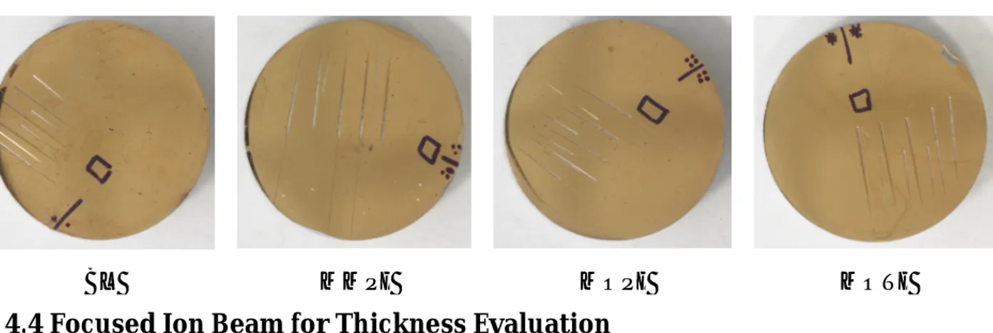
4.4 Focused Ion Beam for Thickness Evaluation ...38
4.5 Nanoindentation Testing ...41
4.6 Scratch Testing ...46
4.7 XRD Residual Stress Measurement ...48
4.7.1 Bragg’s equation ...48
4.7.2 Measurement of strain ...50
4.7.3 Stress calculations ...52
Chapter 5 RESULTS AND DISCUSSION ... 55
5.1 FEM based Design of Stress-Optimized Ti-TiN Multilayer PVD-Coatings ...55
5.1.1 Stress analysis in bilayer and multilayer coating configuration ...55
5.1.2 Residual stress optimization in multilayer coating configuration ...59
5.1.3 Conclusions...64
5.2 Influence of Ti-TiN Multilayer Coating Design on Mechanical ...65
Properties and Scratch Adhesion...65
5.2.1 Focused ion beam thickness evaluation ...65
5.2.1 Nanoindentation testing ...66
5.2.3 Scratch adhesion testing ...68
5.2.3.1 Standard scratch test with indenter of radius 200 μm ...68
5.2.3.2 Scratch test with indenter of radius 100 μm ...73
5.2.3.3 Analytical description of adhesive and cohesive failures...76
5.2.4 Conclusions...78
5.3 Influence of Ti-TiN Multilayer Coating Design on In-Plane Residual ...79
Stresses ...79
5.3.1 X-ray diffraction residual stress analysis...79
5.3.2 Conclusions...80
Chapter 6 SUMMARY AND OUTLOOK ... 81
6.1 Original contribution to the scientific community ...82
6.2 Suggestions for future research ...82
6.3 List of Publications ...83
References ...83
v List of Figures
Fig. 2.1 Structural zone model for growth in metal films: (a) Model of Movchan-Demchishin [9]; (b) Model proposed by Thornton [10]. ... 6 Fig. 2.2 Structure zone diagram applicable to energetic deposition ... 8 Fig. 2.3 Schematic diagram for the development of residual stress in zone-T structure: (a) Average stress in zone-T layers having various structures (full circle: single CrN layer with V-shaped morphology; full square: CrN top layer with equi-axed columnar structure); (b) The growth stress component [σsh, σdiff and σip originating from volume shrinkage during grain growth, ad-atom diffusion to grain boundaries and ion-peening under conditions of high kinetic energy, respectively]. Source [14] ...10 Fig. 2.4 Schematic of residual stress related failure mode in coatings: (a) Edge delamination (high in-plane stress and weak interface), (b) Delamination under high tensile stress with weak interface, (c) Buckling under in-plane stress, and (d) Bridge cracking, i.e. coating under tensile stress having strong interface, Source: [15] ...12 Fig. 2.5 High in-plane stress in combination with unfavourable geometry: (a) Coating on smooth 90° substrate edge, (b) A periodically rough substrate surface, (c) High in-plane stress in attached configuration, and (d) Stress re-distribution as a result of delamination. ...13 Fig. 2.6 High in-plane stress in combination with unfavorable geometry: (a) A partially detached TiAlN coating at edge of cutting tool [18], (b) Cross-section indicating the initiation of fracture at small convex curvatures, i.e. substrate roughness effect, (c) Delaminated layer of ZnO on Si [19]. (d) The PVD TiB2 with ≈ 10 GPa compressive stress on austenitic stainless steel [17]...13 Fig. 2.7 Multilayer coating system in comparison with bilayer used for artificial knees: (a) Enlarged image at a point on artificial knees, (b) Cross-sectional view showing individual layer thickness, (c) Monolayer system grain morphology, (d) Multilayer structure showing hardness gradient. ...15 Fig. 3.1 Classification of stresses in coatings ...20 Fig. 3.2 (a) Materials behaviour in terms of stress-strain curve, and (b) Thickness dependent intrinsic stress reproduced in TiN. ...23 Fig. 3.3 Schematic description of finite element model (not to scale) realized to evaluate residual stress arising from deposition process. ...25 Fig. 3.4 Geometry of an element ...26 Fig. 3.5 Followed optimization frame work ...31 Fig. 3.6 Figurative description of the mathematical method (method of image indenters): (a) The result for the region z ˂ h (z ˂ 0), i.e. the observer located within the layer, (b) For the observer within the substrate z ≥ h (z ˂ 0) where h is thickness of coating. Source [46] ...32 Fig. 4.1 Schematic arrangement: (a) DC sputtering, and (b) RF sputtering ...37 Fig. 4.2 The magnetron sputtering arrangement and sputtering plant: (a) Planar and annular magnetron sputtering arrangement, (b) Photograph of magnetron sputtering deposition facility. ...37 Fig. 4.3 The FIB principle, from left to right: Imaging, Milling and Deposition. Source [52] ...39 Fig. 4.4 The FIB cross section: (a) Single layer, (b) Multilayer TiN coating showing the sacrificial layer, interlayer and bond layer. ...41 Fig. 4.5 Nanoindentation equipment: (a) Nano Indenter G200, (b) Schematic representation. ...41 Fig. 4.6 Schematic description: (a) Schematic description of load (P) versus displacement into material (h) curve with basic parameters, (b) Schematic of contact geometry under action of load P; plastic deformation within area of contact and elastic deflection (sink-in) to the edge of contact area, (c) Contact geometry for a load P (loaded) and following the removal of indenter (unloaded). ...42
vi
Fig. 4.7 Schematic summary of the procedure followed (Oliver-Pharr [56, 57]) for the calculation of hardness and elastic modulus for a standard nanoindentation test. INPUT is a generic curve
Load-displacement, OUTPUT is the hardness and elastic modulus calculated at the maximum load. ...45
Fig. 4.8 Schematic illustration of scratch test instrument. Source [59] ...47
Fig. 4.9 Bragg’s Conditions ...48
Fig. 4.10 Plane stress elastic model. Source [61] ...51
Fig. 4.11 Coordinate systems used for stress and strain calculations: (a) Principal axis of strain, (b) principal stress corresponding to stress and strain orientations. ...51
Fig. 4.12 Linear dependence of inter-planar spacing of plane (311) upon sin2Ψ for 5056-O aluminum shot peened alloy. Source [62] ...53
Fig. 5.1 Predicted average in-plane normal stress in multilayer configuration (MMPI) ...56
Fig. 5.2 Qualitative comparison of predicted shear stress in model BL in comparison with model MMPI ....58
Fig. 5.3 Qualitative comparison of predicted normal to surface stress in model BL in comparison with model MMPI ...59
Fig. 5.4 Qualitative comparison of predicted normal to surface stress profile in two models of multilayer configurations, MOPI and MOTI in comparison with model MMPI. ...62
Fig. 5.5 Qualitative comparison of predicted in-plane shear stress profile in two models of multilayer configurations, MOPI and MOTI in comparison with model MMPI. ...63
Fig. 5.6 The FIB cross-section observation (30 kV, ETD, 65000x in all cases): (a) sample BL, (b) sample MMPI, (c) sample MOPI, (d) sample MOTI. Columnar structure and presence of Ti layer is clearly visible. ...65
Fig. 5.7 Intrinsic hardness and elastic modulus of bilayer and multilayer configurations ...67
Fig. 5.8 Optical profilometer images at first critical (buckling cracks) failure in bilayer and multilayers: (a) Sample BL, (b) sample MMPI, (c) Sample MOPI, and (d) Sample MOTI. ...68
Fig. 5.9 Optical profilometer images at second critical (chipping at border with partial delamination inside scratch track) failure in bilayer and multilayers: (a) Sample BL, (b) Sample MMPI, (c) Sample MOPI, (d) Sample MOTI. ...71
Fig. 5.10 Optical profilometer images at complete delamination failure in bilayer and multilayers: (a) Sample BL, (b) Sample MMPI, (c) Sample MOPI, and (d) Sample MOTI. ...71
Fig. 5.11 Critical scratch loads in bilayer and multilayer configurations. ...72
Fig. 5.12 Optical profilometer images at first delamination failure (partial appearance of substrate) in bi-layer and multilayers: (a) Sample BL, (b) Sample MMPI, (c) Sample MOPI, and (d) Sample MOTI. ...74
Fig. 5.13 Images with optical profilometer at complete delamination failure (semicircular appearance of substrate) in bi-layer and multilayers: (a) Sample BL, (b) Sample MMPI, (c) Sample MOPI, and (d) Sample MOTI. ...75
Fig. 5.14 Critical scratch loads in bilayer and multilayer configurations. ...76
Fig. 5.15 Simulated position of von-Mises stress in bilayer with the critical scratch load (LC1) along with critical failure mode: (a) With 100 µm indenter radius, (b) Optical profilometer image at the incident of critical failure, (c) With 200 µm indenter radius, and (d) Optical profilometer image at the incident of critical failure. ...77
vii List of Tables
Table 3.1 Physical and thermal properties of inter-layer, coatings and substrate materials ...23
Table 3.2 Physical properties of inter-layer, coatings and substrate materials ...34
Table 5.1 Iteration results of multilayer MMPI under Ti interlayer thickness variation ...60
Table 5.2 Optimization iteration results for multilayer with optimal position of inter-layer (MOPI) ...60
Table 5.3 Optimization iteration results for optimal position and thickness of interlayer (MOTI) ...61
viii
Acknowledgements
I have no words to express my deepest sense of gratitude to Almighty Allah, the Most Merciful and the Beneficent, Who bestowed upon me the courage, health and will to complete this project, and contribute a little to the field of knowledge and science.
First, and the foremost, I would like to thank my supervisor, Prof. Edoardo Bemporad, for his valuable guidance and facilitation throughout the research and in the preparation of this thesis. My sincere thanks to Dr. Marco Sebastiani for his constant guidance and encouragement for the completion of this research work. I would like to express my thanks to the University of “Roma Tre” Engineering Doctorate School for the financial support, including the scholarship during my studies and grateful acknowledgement for the additional funding in response of work for the “Istress” project. Dr. Marco Sebastiani deserves special thanks for the additional funding.
I would like to extend particular thanks to Marco Renzelli, Dr. M. Zeeshan Mughal and Dr. Antonio Cusma for their suggestions throughout the research period and writing of this dissertation. I would like to thank for the cooperation of current and past members of the Materials Science and Technology Group (STM), including, Andrea D’Abronzo, Fabrizia Vallerani, Federico Massimo, Giuditta Montesanti, Dr. Mattia Piccoli, Dr. M.Boota, Dr. Luca Mazzola and Dragana Nikolic. Many thanks to Daniele de Felicis, Riccardo Moscatelli and Vincehzo Mangione for their technical help, they taught me all about Scanning Electron Microscope, Nanoindenter, Optical profilometer and Dr. Marco Sebastiani, who taught me the Modelling skills and how to write the science. I deeply acknowledge my uncle Prof. Abdul Ghafoor for perpetual encouragement, moral support and technical as well as refining the language of this thesis.
I have no words to thank the Administration, especially Prof. F. Ahmad Khalid (Ex. Pro-reactor academic), Prof. J. Ahmad Chattha (Pro-reactor academic) and Dr. Fida Mohammad (Dean FMSE), of the GIK, Topi, Pakistan for encouraging and granting me leave for Ph.D. studies at University of Roma Tre, Rome, Italy.
I would like to thank my parents for their continued support and congregations for my success. I am deeply indebted to my wife Mrs. Nusrat Parveen for continuous encouragement for higher studies; my son M.Umar Sindhu and daughter Tahreem Rashid for patiently and sometimes eagerly kept waiting for completion of my studies and return to Pakistan.
1
Chapter 1 INTRODUCTION
1.1 Significance of the Investigation
Thin film technology is growing field as the number of its application is increasing day by day with the advancement and miniaturization. In industrial applications, the effective way of protecting and increasing the life-time of engineering components operating in corrosive, erosive, high temperature and under heavy contact load is to apply thin hard coating layer. Hard coatings are a class of coatings that have been developed as a surface engineering enhancement solution for cutting tools, dies, drills, moulds and other tribological applications. Today, almost every tool or tribological component is coated which decrease the production cost and perform well. All of these applications are based on the fact that coatings are hard, abrasive resistant, provide low friction surfaces and well-adhered to the material to be protected.
During the past few years, scientific research has been focused on multilayer coatings, which may be very effective for increasing overall coating thickness, improving hardness, adhesion, fracture toughness and controlling the residual stresses. To effectively design a multilayer system for a specific application, it is important to know the mechanical, tribological and structure properties of the coating materials. Hardness of material to be coated, number of coating layers, individual layer thickness and coating production parameters are additional design variables. Of course, the required properties are changed with the change of these properties and variables. If not all, a few basic properties of the coated system such as hardness, residual stress and adhesion have primary importance; which are also relevant and common to a wide range of applications. Among them, residual stress state could significantly alter the overall performance, life-time and is essential to control so that coated system could withstand the additional in-service loading stresses without failure.
In view of this, the objective of this PhD thesis was to develop NOVEL DESIGN RULES for the modelling and production of multi-layered coated systems with improved adhesion and optimal
2 surface hardness and wear resistance.
1.2 Gap of Knowledge
Hard-coatings failures on relatively compliant substrate in many tribological situations are caused by delamination of coating from the substrate (adhesive failure) and fracture in coating, i.e. cohesive failure [1, 2]. The failures are sometimes related with relatively high compressive residual stress and stress gradient through coating thickness. An increase in thickness of metallic layer could provide a reduction of in-plane stress but could significantly decrease the performance of the multilayer coating system [3]. Alternatively, multilayer configuration having equal thickness of ceramic layers could have different amount of residual stress. In case of comparatively thick titanium nitride (TiN) ceramic layer near to the substrate results in a large in-plane residual stress (dense columnar growth at the start is present), which usually causes the system’s failure due to crack propagation [4]. Therefore, a specific thickness of Ti interlayer is required for a particular TiN coating thickness. The optimum coating layer thickness could further enhance the performance of multilayer in terms of adhesion and toughness. Nonetheless, most of the studies focused on the development and characterization of multilayer coatings and only a few on the multilayer coating architecture design [5]. As a result, further development seems imperative in the design of stress-optimized multilayer physical vapour deposition (PVD) coatings.
The starting point for the present work was the previous work by Bemporad et.al. [5] in which they investigated the effect of a titanium buffer layer position on the decrease of interfacial stress that improved the adhesion of TiN based systems by Finite Element Modelling (FEM) and micro-mechanical testing. A four-layer Ti-TiN multilayer coating was numerically analyzed and experimentally tested. In their work, only three Ti-TiN multilayer (four layers) configurations were simulated. They demonstrated that having a lower position of the Ti buffer layer improved the adhesion of coating to the substrate. However, a fully automated procedure to find the optimal position of the Ti buffer layer still has to be developed. In addition, the analysis and optimization of systems with the inter-position of the two (or more) Ti layers has not been investigated, yet. In the
3
present work, finite element Modelling of residual stress analysis coupled with the ANSYS optimization algorithm was used to design and develop a stress-optimized Ti-TiN multilayer configuration comprising of 6-layers.
1.3 Objective, Approach and Scope of Investigation
The objective of this thesis is the finite element Modelling based design of Ti-TiN multilayer coating system to find optimal thickness of each layer that decrease interfacial stresses responsible for delamination failure in coating. As interface delamination is one of the major failure modes of hard coatings on stiff and compliant substrate.
Such an approach could be used to develop stress-optimized multilayer coatings with minimal experimental work and help save resources during trial and error efforts. The developed optimization procedure can be used to design interfacial stress-optimized multilayer coating comprising of many layers to meet a variety of functional requirements. Further, at multilayer coating production scale, such optimization tool could be more refined to be implemented for particular multilayer (metallic/ceramic) coated systems. In addition, the finite element Modelling based measures are important to consider the coating at the preliminary component design stage instead of using as finishing operation. In general, the main aim of this work was to develop knowledge-based design tool for the multilayer coating architecture optimization considering microstructure-related functional properties of thin films such as residual stress, elastic modulus, hardness, toughness and wear resistance.
1.4 Thesis Overview
The thesis has been organized into six chapters. Chapter 2 presents a literature review on the evolution of residual stress in magnetron sputtering PVD-coating and their influence on failures in coating. The multilayer approach to control the residual stress and procedure adopted so far for the stress-optimization of multilayer coating architecture. Chapter 3 is about the details of the
4
Modelling activities used to design stress-optimized multilayer coating configuration and in Chapter 4, experimental techniques used in the present thesis are described in details.
Chapter 5 summarizes the modelling and experimental results in three sections. In the first section results of finite element based design of stress-optimized Ti-TiN multilayer coating is summarized. In the second section, influence of Ti-TiN multilayer coating design on the mechanical properties and practical scratch adhesion are described in detail. The third section is about the influence of coating design on the in-plane residual stress. Finally, the thesis is summarized in Chapter 6 with the contributions and the remaining interesting tasks.
5
Chapter 2 LITERATURE REVIEW
2.1 Introduction
Residual stress in PVD-coating is a function of film thickness, elastic modulus of coating material, morphology and film density. Sometimes, stress level could be equal to yield strength of the material for example in case of high elastic modulus materials such as tungsten, metal nitride and metal oxide. For low-modulus material such as gold, silver and titanium, yielding will relive the stresses before to develop high stress level [6]. In addition, similar to elastic modulus residual stress is also structure dependent property. Considering this structure behaviour of residual stress, microstructure and intrinsic stress evolution in thin films are first reviewed in this chapter. Then residual stress related failures in thin films are elaborated followed by multilayer coating practices to control the residual stress and related failures. Finally, the Modelling and optimization approaches to control the residual stresses in multilayer coatings are described.
2.2 Microstructure Evolution in PVD-Coatings
The microstructure of thin film could substantially influence the functional properties such as mechanical, optical and electrical. Microstructure to a larger extent is determined by the grain size, morphology and grain boundary morphology. The important characteristic of coating production through deposition is the microstructure modification for the enhancement in mechanical properties in comparison with bulk counterpart material [7]. For example, Ti thin films has elastic modulus equivalent to the bulk Ti but has enhanced plastic properties. The nature of high plastic behaviour was found to be dependent upon film thickness. As with the thickness in sub-micron range, the typical finer grain size present in metal film. Also, the evaluation technique used for the determination of plastic properties could caused large strain gradients which usually lead to geometrically necessary dislocations for the enhanced plastic properties [8]. Therefore,
6
understanding the process behind the microstructure evolution is imperative, especially for the development of coatings used in mechanical applications.
The evolution of thin film microstructure during growth is highly dependent on the deposition conditions. This has lead to the development of the structure zone model (SZM) for the provision of an overview of the relationship between microstructure of coatings and common deposition parameters. The first such model was presented by Movchan and Demchisin [9] through which influence of deposition temperature on the microstructure was assessed as a function of homologous temperature or deposition temperature normalized to the melting temperature of the deposited material (Tdep /Tmelt). This model was ten year work of Movchan-Demchishin in which thick and thin coatings of Ti, Ni, W, ZrO2, Al2O3 were deposited with electron beam evapouration on substrate over which temperature gradients were maintained. According to this model, coatings are characterized with zone 1, zone 2 and zone 3 (Fig. 2.1a).
(a) (b)
Fig. 2.1 Structural zone model for growth in metal films: (a) Model of Movchan-Demchishin [9]; (b) Model proposed by Thornton [10].
The zone 1 in the structure zone model (Fig. 2.1a) corresponds to low temperature at which ad-atom diffusion is small which results in grains with domed tops, high density of lattice imperfections and
7
porous (voided) grain boundaries; hence the term ‘porous columnar’ is used to describe this type of structure. At significantly higher deposition temperature ad-atom diffusion/mobility becomes significant and zone 2 structure evolves with large columnar grains and dense grain boundaries. At temperature close to melting temperature (Tdep /Tmelt > 0.8), the film consists of large equiaxed grains comparable to film thickness due to both the surface and bulk diffusion of ad-atom (zone 3). However, the microstructure of metallic film deposited with sputtering depends on transfer of energy from energetic particle to the growing films. Considering this fact, Thornton [10] added an additional axis in the model to account for the sputtering gas pressure (Fig.2.1b). According to Thornton model, zone 1 structure is promoted with substrate roughness, low temperature and high argon pressure. At low temperature atoms have extremely low mobility on the surface; they tend to stick where these land on the substrate. It could persist even at higher temperatures due to substrate roughness and is promoted even on smooth substrate with high inert gas pressure. A fourth zone consisting of a dense array of poorly defined fibrous grains identified between zones 1 and zone 2 and is termed as zone T. The zone T is believed to be a transition zone. The zone T structure is formed by either thermally inducing greater ad-atom mobility or by ion bombardment. Momentum exchange then causes the coating atom to fill the boundaries of loosely packed zone 1 column.
Further, Messier [11] have found that bias potential on the substrate induce ad-atom mobility which appears to be mostly affecting the physical structure rather than pressure induced bombardment by ad-atom mobility. Therefore, the pressure axis in Thornton’s model is replaced by floating bias potential of the substrate to account for the separate contribution of bombardment to ad-atom mobility. The purpose to apply the bias on substrate is also to increase the total energy arriving at the substrate, so Musil et al. [12] have suggested the replacement of bias voltage with an energy parameter, Ep. Later the energy parameter Ep has been replaced with universal parameter ion-to-atom arrival ratio.
8
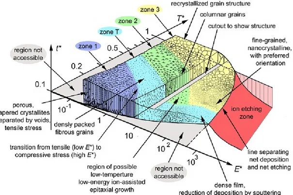
The latest and recently proposed universal structure zone diagram (SZD) is by Anders [13], who still considered it originally the three structure zone and a transition zone (Fig. 2.2). There, film growth is classified according to thermal activation, T*, which includes homologous temperature plus temperature shift caused by the potential energy of particles arriving at the film surface and kinetic activation E*, describing displacement and heating effects caused by kinetic energy of bombarding particles. A third axis considers the net film thickness t*, which provides to maintain the qualitative illustration of film structure while indicating thickness reduction by densification and sputtering. The diagram also includes a “negative thickness” due to the effect of ion etching at excessive ion energies and intensities.
Fig. 2.2 Structure zone diagram applicable to energetic deposition
2.3 Residual Stress Evolution in PVD-Coatings
The general state of stress depends on deposition conditions as well as on structure, morphology and thickness of coatings. The stress evolution in hard transition metal nitrite coating is important to understand the origin of intrinsic stress and to control the stress level in order to avoid residual
9
stress related failures. It could help to engineer the coating system with required level of residual stress.
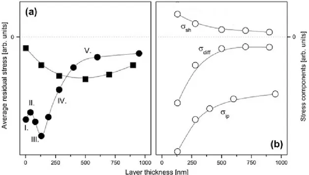
In general, coating with zone T (transition region) could result in high intrinsic stress due to dense fiber structure with smooth and highly reflective surface. The zone1 structure is too porous to support intrinsic stress. Recovery and recrystallization limits the intrinsic stress in zone 2 and 3. Daniel et.al [14] and all the references therein, analyzed the origin of intrinsic stress in magnetron-sputtered thin films with zone T-structures. The evolution of the average stress with the film thickening is schematically shown in Fig 2.3. At the early film growth (region-I), compressive stress is caused by the isolated crystallite islands prior to coalescence. The development of compressive stress only proceeds until the island establishes large area across the growth surface. The interaction forces acting across voids between adjacent islands to force them to come in contact and interact within the elastic distortion from the original position. This interaction generally results in energy gain originating from the decrease in surface area through formation of grain boundary out of the free surfaces of two adjacent islands. Formation of a continuous layer by closing all the gaps between adjacent islands is then accompanied by a film volume decrease that induces development of tensile stress (region-II). It is named as shrinkage stress (σsh) originating from volume shrinkage accompanied with grain growth (Fig. 2.3b). The maximum tensile stress indicates the end of coalescence process, although its magnitude depends on the grain boundary motion and the number of voids annihilated between the grains during coalescence. Surface ad-atom mobility also contributes to the stress development and it determines whether the tensile stress decrease in the magnitude or become compressive with increasing film thickness. That is, only under high mobility diffusion condition in which excess sputtered adatom to the grain boundaries occurs that give rise to compressive stress (region-III). This is named as ion-peening stress (σip) component (Fig. 2.3b). The mechanism for the incorporation of surface adatom into grain boundaries decrease their free energy that is more likely at higher substrate temperature or under ion irradiation. However, grain boundaries are microstructure and thickness dependent. From this, continuous
10
increase in grain size is observed as the layer thickens under continuous flux of sputtered material. The grain growth proceeds with the annihilation of grain boundaries which subsequently leads to a decrease in the total area of grain boundary surface and thus to decrease of the number of ad-atom incorporated there. In addition, diffusion flux towards grain boundary area is suppressed with the existing compressive stress which increases chemical potential of atoms in the grain boundaries. Both of these effects contribute to decrease the compressive stress component (region-IV). It is stress component (σdiff) due to ad-atom diffusion to the grain boundaries (Fig. 2.3b). The evolution of low-density atomic structure along grain boundaries evolves during grain growth into a dense well-organized grain structure; the subsequent volume shrinkage is accompanied by the development of tensile stress (region-V).
Fig. 2.3 Schematic diagram for the development of residual stress in zone-T structure: (a) Average stress in zone-T layers having various structures (full circle: single CrN layer with V-shaped morphology; full square: CrN top layer with equi-axed columnar structure); (b) The growth stress component [σsh, σdiff and σip originating from volume shrinkage during grain growth, ad-atom diffusion to grain boundaries and ion-peening under conditions of high kinetic energy, respectively]. Source [14]
11
evolution through sequence of growth stages; including nucleation, island growth, coalescence of islands formation of continuous structure and subsequent film growth. Every growth stage is essentially characteristic of unique film forming processes that give rise to generation of growth (intrinsic) stress which differs in magnitude and can be either tensile or compressive.
2.4 Residual Stress Related Failures in Coatings
Residual stresses are commonly present in coatings irrespective of deposition techniques. Overall performance of coatings is closely related to the process induced residual stress. For instance, compressive stress is often desirable as many coating materials (brittle) are stronger in compression than tension. It also increases the hardness of coating but excessive stress can decrease the adhesion of coating to the substrate. Hard coating failures on relatively compliant substrate are caused by delamination of coating from the substrate (adhesive failure) and fracture in coating, i.e cohesive failure [1]. The failures are primarily related with relatively high compressive residual stress and stress gradient in the coatings.
In principle, the interior of ceramic films have equi-biaxial in-plane compressive residual stress which could cause delamination at edges which is schematically shown in Fig. 2.4a.
(a) (b)
12
Fig. 2.4 Schematic of residual stress related failure mode in coatings: (a) Edge delamination (high in-plane stress and weak interface), (b) Delamination under high tensile stress with weak interface, (c) Buckling under in-plane stress, and (d) Bridge cracking, i.e. coating under tensile stress having strong interface, Source: [15]
The residual stress level is characteristic of a specific material combination (coating and substrate) and manufacturing process. Fig. 2.4 shows failure mode in coating under different state of stress. It is seen that in-plane tensile stress in coating cause delamination and fracture within coating (Fig. 2.4b and Fig. 2.4d).
In general, three possible failure mechanisms in coating under tensile residual stress can occur [16]. For example, a brittle coatings fracture by development of cracks through coating thickness (Fig. 2.4d). Tougher coating may fail by delamination along the interface (Fig. 2.4b) or by propagation of crack in the substrate. However, residual compressive stresses could cause edge delamination, buckling and prompt crack initiation and propagation within the coating. It is seen that failure modes are also affected by the relative strength of coating-substrate interface.
In addition, it is well-established that ceramic coated circular disk-shaped metal components mainly fail by the magnitude of axial stress at or near the radial free edge of the specimen. The associated failure of de-cohesion at metal-ceramic interface resulted in progressive delamination and spallation of coatings. Analytical and finite element models as well as experimental studies showed the influence of these stress components on coating failures. Also, when coating is applied on engineering components with geometrical features like edges, corners, notches and relatively rough surfaces generate interfacial stresses. It is also named as lift-off stress. The lift-off stress magnitude is further increased with tribological service loadings. The stress level could exceed up to 50 % of residual stress [17]. Fig. 2.5 schematically shows some of stress concentrations arise with unfavourable geometry and high in-plane stress whilst Fig. 2.6 shows actual (real-time) failure mode examples.
13
Fig. 2.5 High in-plane stress in combination with unfavourable geometry: (a) Coating on smooth 90° substrate edge, (b) A periodically rough substrate surface, (c) High in-plane stress in attached configuration, and (d) Stress re-distribution as a result of delamination.
Fig. 2.6 High in-plane stress in combination with unfavorable geometry: (a) A partially detached TiAlN coating at edge of cutting tool [18], (b) Cross-section indicating the initiation of fracture at
(a) (b)
(c) (b)
(a) (b)
14
small convex curvatures, i.e. substrate roughness effect, (c) Delaminated layer of ZnO on Si [19]. (d) The PVD TiB2 with ≈ 10 GPa compressive stress on austenitic stainless steel [17].
In all the cases mentioned above, the residual stress deviates from perfect bi-axial stress state. As a result interfacial normal and shear stresses are generated which are exaggerated with 2-D plane stress element in Fig. 2.5a. Under this stress orientation, maximum principal stress is suspected to cause the initiation of cohesive fracture (Fig. 2.6a). However, the interface has lower strength generally than either of coating or the substrate. To avoid possible coating delamination, therefore interfacial (across interface and shear stress along the interface) residual stress analyses are usually performed under such situations.
2.5 Multilayer Coatings
Multilayer coating is a class of hard layer material in which individual layers of different materials are produced. Individual layer thickness can vary from micro-scale to nano-scale as long as individual layer maintain its properties. The materials properties vary differently; in order to have a coating-substrate system for a specific application, only a few material combinations could results in required level of performance. The important material parameters to be considered in achieving better performance are elastic modulus, coefficient of thermal expansion, morphology of coating and chemical compatibility of the coating and substrate [20, 21].
The mechanical and tribological behaviour of brittle coatings on compliant substrate materials is usually very much influenced by the in-service loading conditions and residuals stresses. To meet the specific functional requirements for various uses, multilayers in comparison with bi-layer, offer much more ease: to control residual stresses, improve adhesion, increase overall thickness, improve abrasive wear, producing the toughening response and adopted for multi-functional use. This has lead to increasing use of multilayer coatings. Multilayer coatings not only offer a combination of properties from different materials but also increase the overall performance of systems.
15
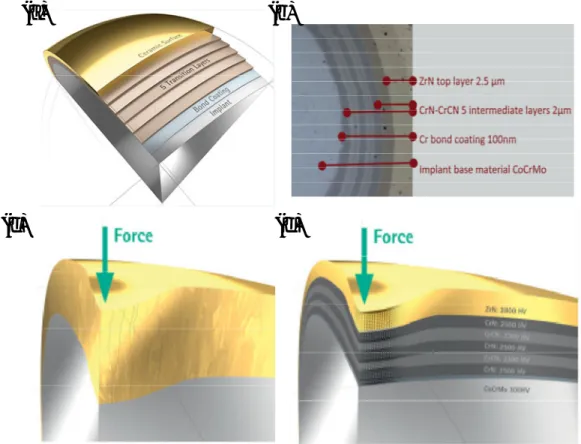
To show a real-time example of multilayer coating system, a commercially available multilayer coating system developed by Aesculap® for the artificial knees implant (Fig. 2.7) [22]. The coating system comprised of seven layers in which external layer of ZrN has exceptional hardness and CrN layer provide the hardness gradient through coating thickness and prevent allergy. The coating system has excellent performance in terms of adhesion, wear and materials fatigue. In view of structure-property relation, multilayer system in comparison with bilayer has refined grains that increase the performance of the coating system; however bilayer has coarse grains of open columnar structure close to surface.
Fig. 2.7 Multilayer coating system in comparison with bilayer used for artificial knees: (a) Enlarged image at a point on artificial knees, (b) Cross-sectional view showing individual layer thickness, (c) Monolayer system grain morphology, (d) Multilayer structure showing hardness gradient.
It is clear from the above-mentioned literature that even though multilayer coatings offer promising solutions for wear resistance applications, the demand of different applications can be met by
(a)
(b)
16
adjusting relative thickness of different layers. For instance, Ma et al. [23] emphasized the need for the optimization of Ti-layer thickness for greater coating adhesion in Ti-TiN multilayer coatings.
2.6 Finite Element Modelling of Residual Stress in Coatings
Coatings systems enhance the performance and increase the lifetime for a wide variety of engineering components. Engineering design approach is commonly used for the design of component before manufacturing for specific functional use. However, coating of component is simply performed as a finishing operation. To obtain a full benefit of multilayer coating it could be considered at the component design stage. For this analytical and FEM optimization measures are therefore required. General design rules need to be found for performance optimization.
Modelling of materials behaviour is common practice in graded materials fabricated at relatively high temperature depending upon their composition to produce composite structure for better properties [24, 25]. Although, the continuum approach is at much larger scale in comparison with micro-structural features but the materials simulated behaviour could be very useful for further refinement and improvement.
Finite element analyses of thermal stresses in Ti-TiN bi-layer verified via analytical calculation is extensively researched. The results suggest that inter-layer decrease the interfacial stresses that improve coating substrate adhesion [26, 27].
2.7 Optimization of Multilayer Coating Architecture
Multilayer coating system with alternate hard and soft layers play a major role for the better performance in tribological and wear applications over mono-layer coatings. However, the role of
overall thickness, number of layers and individual layer thickness cannot be overlooked and need to be optimized. To effectively design a coating architecture for a specific application and
depending upon design constraint of the component, it is necessary to know the state of stress in coatings. For this, measures in terms of stress-optimization seem imperative.
17
Lakkaraju et al. [28] optimized chromium-chromium nitride (Cr-CrN) multilayer coating architecture comprising of eight layers on steel and aluminium substrate subjected to Hertzian contact. The overall coating thickness was fixed to 2 µm and the thickness of Cr and CrN were chosen as design variables. Multi-objective optimization was used to minimize the von-Mises stress in the topmost CrN layer and strain discontinuity in the coating thickness direction along the Cr-substrate interface. The approach in the study provides an important and promising direction for the design of wear-resistant multilayers coating to minimize coating damage under given set of loading conditions. However, the choice of objective function to be minimized, von-Mises stress and strain discontinuity, may not be appropriate to address the damage in the coating. The brittle behaviour of thin CrN layer perhaps required a maximum principal stress type function. Also strain discontinuity seems to be vague parameter to quantify delamination of the coating. A stress-based approach better reflect damage at interfaces.
To address the residual stress related failure in PVD-coatings, a mathematical model of stress analysis was proposed by Lyubimov et.al [29]. The model calculates residual stress as a function of coating layer thickness, deposition temperature, composition and substrate bias voltage. The model addresses the interfacial failure and suggests the use of compliant metal layer to decrease the stress. However, the model involved time-consuming mathematical calculations.
In a study on various design of metal-ceramic (Ti-TiAlN) multilayers deposited onto substrate pre-treated with different plasma-sputtered etching conditions [30]. The different multilayer designs were investigated for their influence on the level of residual stress and mechanical properties. It was found that multilayer with thick ceramic layer has lower compressive stress in ceramic layer. However, multilayer with decreasing ceramic layer thickness in graded fashion towards substrate has higher compressive stress.
The above referred investigations help conclude that multilayer coating offers promising solution to control the residual stress and improve adhesion. In the present work, finite element Modelling of residual stress analysis coupled with the ANSYS optimization algorithm, as a robust measure was
18
use to design and develop Ti-TiN stress-optimized multilayer coating comprising of 6-layres. During the optimization, a realistic bi-axial thickness dependent intrinsic stress (ion peening stress) in each TiN layer was reproduced as an initial in-plane stress. The thickness dependent intrinsic stress for numerical calculations was adopted from the growth-stress model for columnar structures proposed by Daniel. et.al. [14].
19
Chapter 3 MODELLING ACTIVITIES
In this chapter, details about the formulation of Finite Element Model (FEM) for the analyses and optimization of residual stresses in multilayer coatings are provided. The numerical optimization algorithm used and mesh refinement measures are elaborated. In addition to FEM Modelling, the use of analytical Modelling for the analytical description of failures (adhesive and cohesive) during the coating adhesion evaluation is described.
3.1 Residual Stresses in Coatings
A complete state of stress in the PVD-coatings is important for their mechanical performance. Intrinsic stresses in coating itself not leaving the substrate unstressed and could be added to the ones originating from other source such as external loading and temperature etc. Usually, the intrinsic stresses in coating are much smaller than their yield strength otherwise coating will not form at all. High compressive intrinsic stress could cause plastic deformation in the substrate, coating delamination from the substrate. The actual stress during the service is given by Eq. 3.1:
= + 3.1
Where σapp is the external force including the frictional heating during service. General classification of stress in coating is shown in Fig. 3.1.
20 Fig. 3.1 Classification of stresses in coatings
Residual intrinsic stresses in the PVD-coatings mainly arise from contribution and interactions of two sources: the low thermal stresses and the high intrinsic stresses. Thermal stresses arise from thermal mismatch between the coating and the substrate: during final cooling from deposition to room temperature. It effects become exaggerated when multiple layers of materials have different thickness and big difference in stiffness [31]. A thermal mismatch-strain, εth , arises by change in temperature; result in residual stress given by the following Eq. 3.2 [32]:
=
1 − . = 1 − . − . ( − ) 3.2
Where Ef and f are Young’s modulus and Poisson’s ratio of the film; (
) = bi-axial elastic modulus of the film; αf and αs are thermal expansion coefficients of the film and the substrate, respectively; { }; { } are the room and deposition temperatures of the substrate, respectively. The quantity is the stress that will develop in the thin film. Here, only differential thermal stress is considered; however thermal expansion is structure dependent property which could vary with the layer thickness.
Internal/ Residual stress External stress
Service loading Thin coating stresses
Geometric constraints
Intrinsic/Growth stress Extrinsic/Thermal stress
Difference in thermal expansion of coatings and substrate
Recrystallization process
Grain growth Phase transformation
Variations of interatomic spacing with the crystal size Microscopic voids and arrangement of dislocations
21
The intrinsic stresses in PVD-coatings arise during deposition and its magnitude depends on deposition conditions, such as reference potential on the substrate, pressure of the working gas and the target to the substrate distance, as well as on stoichiometry and thickness of coating-layer [33-35]. Usually, the resulting residual stress field is formed by a simple superposition of the two sources (Eq. 3.3):
= + 3.3
In addition, intrinsic stresses in the PVD-coatings are thickness-dependent although the stress gradient through coating thickness is common.
3.2 Finite Element Analysis of the Residual Stress
In general, analytical procedures have been developed to evaluate the average in-plane thermal stresses in bi-layer and multilayer coating-substrate systems based on linear-elastic calculations and uniform temperature [36, 37]. However, it is difficult to carry out stress analyses analytically for multi-layered coating systems and numerical methods, therefore, are followed. Also, for more detailed stress analyses, 2-D or 3-D numerical method such as FEM has been successfully developed. The FEM application could overcome the difficulties mostly associated with laborious solution of analytical equations and can be easily used to simulate stress distribution for the temperature gradient.
Finite element models have been successfully used to investigate the influence of inter-layer on the thermal stress in coatings [27, 38]. The thermal stress is effectively decreased with combination of coating and substrate material properties, interlayer material, coating thickness and interlayer material thickness. Stress concentration with abrupt change in materials behaviour at coating-substrate interface can cause propagation of cracks parallel to interface and therefore, could cause coating delamination.
Thus FEM can be considered as an efficient tool to simulate the residual stress problem in multilayer coating system because of its robustness and ease in solving problems with complex geometries including material nonlinearity as well as formulations of different types of problems. In
22
the present work, FEM Modelling is used to design stress-optimized Ti-TiN multilayer coatings with optimal coating layer thickness. For this, finite element package ANSYS coupled with optimization module was used. Finite element models developed so far for stress analyses did not take into account the intrinsic residual stress. To fill this gap, thickness dependent intrinsic stresses were considered in model.
3.3 Finite Element Modelling Consideration
3.3.1 Materials properties
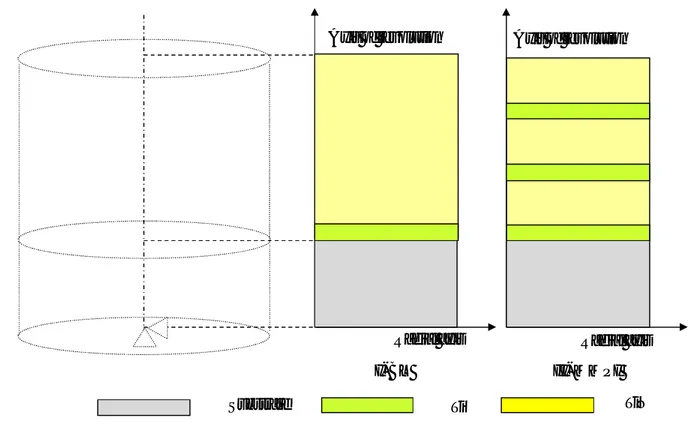
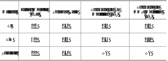
The structure dependent materials properties such as elastic modulus, thermal expansion coefficient and materials behaviour are shown in Table 3.1[27, 39]. Material properties were assumed as temperature independent and residual thermal stresses were computed for simulated cooling from uniform deposition temperature (250 °C) as stress-free temperature to room temperature (25 °C) of the substrate. Deposition temperature was sufficiently low to ignore thermal diffusion effects. Plastic hardening behaviour of substrate, an ideal elasto-plastic behaviour of Ti metallic layer equivalent to bulk Ti and TiN layer was considered as purely elastic for its brittle nature [39, 40]. The materials behaviour is shown in the form of stress strain curve in Fig. 3.2a. In addition to material thermal response, materials thickness dependent intrinsic stresses were considered in the Modelling. A realistic bi-axial thickness dependent intrinsic stress (ion peening stress) in each TiN layer was reproduced as an initial in-plane stress using the INISTATE command in ANSYS. The thickness dependent intrinsic stress for numerical calculations was adopted from the growth-stress model for columnar structures (Fig. 3.2b) [14].
23
Table 3.1 Physical and thermal properties of inter-layer, coatings and substrate materials
Materials Elastic Modulus
(GPa) Poisson’s Ratio
Thermal Expansion (10-6 °C-1)
Materials Behaviour
Ti 116 0.32 9.0 Ideal Elastic Plastic
TiN 600 0.25 9.4 Perfectly Elastic
Substrate 200 0.30 13.0 Plastic Hardening
Fig. 3.2 (a) Materials behaviour in terms of stress-strain curve, and (b) Thickness dependent intrinsic stress reproduced in TiN.
3.3.2 Description of model
For the Modelling of residual stress under the influence of thermal and intrinsic stresses generated in TiN and Ti coatings deposited with magnetron sputtering, a 2D axi-symmetric stainless steel model of 600 μm diameter and 300 μm thickness was formulated in ANSYS multi-physics with Parametric Design Language (APDL). Model is built in parametric form to enable changing these parameters during optimization. The APDL model consists of a circular disk-shape, which exactly reproduces the actual sample shape and has significant dimension in comparison with coating
24
thickness considered in this study. In addition, the model dimension throughout the numerical calculations remained same for the qualitative comparison of results. Following were the simplifying assumptions in this model:
i. The interfaces (coating/substrate, multilayer) were assumed to be perfectly bonded. In finite element, terminology, the nodes are shared at all the interfaces.
ii. Coating and substrate materials were assumed as homogeneous isotropic and linear thermo-elastic.
iii. The structure dependent materials properties were also assumed as thickness independent. iv. Equal bi-axial intrinsic stress in x and z-directions was reproduced in all the TiN layers.
v. Residual thermal stresses were computed for simulated cooling from an assumed deposition temperature (300 °C) as stress-free temperature to room temperature (25 °C) of the substrate. This is maximum temperature that can be developed in the PVD coating system used in the present study.
Two models were formulated one of Ti-TiN bi-layer and other Ti-TiN multilayer with middle position of interlayer. The two models developed are described as follows (thickness of layers is always starting from top layer):
i. Model type of bi-layer “BL” (single layer of 2.55 μm thickness and Ti inter-layer of 0.05 μm thickness);
ii. Model type multilayer with middle position of Ti inter-layer “MMPI” (three TiN layers each of 0.80 µm thickness and three inter-layer of Ti each of 0.06 µm thickness).
25
Fig. 3.3 Schematic description of finite element model (not to scale) realized to evaluate residual stress arising from deposition process.
3.3.3 Description of element
Materials behaviour was simulated with axi-symmetric thermal element PLANE77. The element was 2-D thermal element, eight nodes (quadrilateral form) or six nodes (triangular form) and only has temperature degree of freedom at each node. For a coupled thermal-structural analysis, the element was automatically replaced with an equivalent structural element PLANE183. The structural element was eight nodes (quadrilateral format) or six nodes (triangular format) and has two degree of freedom at each node: translation in x and y directions. This element has material plasticity, elasto-plastic, stress stiffening and initial stress supporting capabilities. These elements were also used during the FEA optimization. The geometry of an element (Fig. 3.4) has quadrilateral or triangular areas and nodes are indicated by dots except for element midside node that acted as connector between the two or more elements. All the elements that shared a node had the same displacement components at that node.
Radial axis Radial axis
Axis of revolution
Substrate Ti TiN
I- BL II- MMPI
26 Fig. 3.4 Geometry of an element
3.3.4 Meshing and validation of numerical model
The previously described, quadrilateral shaped element was used to mesh the model. A finer mesh size was introduced into the model along the thickness of coating in a graded fashion (biasing element size) in order to minimize element size both from the coating and substrate sides towards the coating-substrate interface and other interfaces, in case of multilayer coating. The interfaces were expected to be sharp with high stress concentration as the PVD magnetron sputtering was low temperature process without significant diffusion between the layers. A finer mesh was also introduced close to edge in a graded fashion across the thickness of the coating and substrate. While in lower part of the substrate, an increasingly coarse mesh was used in order to decrease the computational time.
In addition, for the refinement of mesh in multilayer coating configurations, numerical model was validated through numerical tests under different material properties and dimension values of the coating and substrate. A change in thermal residual stress with a change in thickness was also verified with analytical solution [41]. This was accomplished by the reduction in bending induced stress with an increase in layer thickness. This effect was significant for the axial stress; however, for the in-plane stress, it was less significant. The thickness of the each layer was simulated with sufficient number of elements (number of elements in thickness direction) to have stress distribution within each layer. In addition, the bottom left corner of axi-symmetric model was fixed for bending
27
to occur during cooling that changed the residual stress with a change in thickness of the coating layer during the optimization. These boundary condition does not relieve the in-plane intrinsic stress which was reproduced in each layer during optimization. The analysis was first performed to assess the independent effect of thermal stress and validate the in-plane stress with analytical calculation. Elastic theoretical calculation were performed to calculate the average stress using analytical relation given in Eq. 3.4 and 3.5 [36].
= ( ∆ ) 3.4
Where,
= ( ) ∆ )
+ 3.5
Then combined effects of thermal and intrinsic stresses on axial stress profile were examined.
3.4 Finite Element Optimization of Residual Stress in Multilayer Coating
For the residual stress optimization in multilayer coatings, the thickness of individual layers need to be optimized. For this, FEM residual stress analyses coupled with ANSYS optimization algorithm (build in) was used to develop stress-optimized Ti-TiN multilayer coatings.3.4.1 Single-objective optimization procedure
The goal of optimization was to determine optimum value of design variables those minimize or maximize the objective functions. If the objective is to find a maximum of the function “f”, it will be minimization of function – f. Optimization algorithm contains three components: design variable (independent variables), constraints (dependent variables) and objective function (dependent variables) to be minimized. Within specified lower and upper limits of design variables and constraints, the optimization algorithm will search in design space for the minimization of objective function with analysis-evaluation-modification cycle as shown in Fig. 3.5 [42]. As per optimization cycle, an analysis of initial design is performed, results are evaluated against specific design criterion, and the design is modified accordingly.
28
The procedure of single-objective optimization implemented in ANSYS subproblem algorithm is described here. In mathematical form, the standard single-objective optimization statement can be defined as Eq.3.6 and 3.8:
Minimize ( ) = ( , , … … , ) 3.6
Subject to ( ) = ( , , … … , ) ≤ 0 , = 1, … . , 3.7
and ℎ ( ) = ℎ ( , , … … , ) = 0, = 1, … . , 3.8
Where, f is objective function to be minimized and x = ( x1 , x2 ,..., xn ) and is design variable with lower and upper limits. While hi and gj are vectors of equality and inequality constraints also called linear and non-linear constraints, respectively. The limits on design variable and state variable make the optimization problem as constrained one. The sub-problem program establishes relationship between objective function and design variable by curve fitting. This is done by calculation of objective function for several sets of design variables value (i.e. performing the least squares fit between the data points of several designs). The resulting curve is called an approximation. Each optimization loop generates new set of data points, and the objective function approximation is updated. In the similar way, an approximation is generated for each of the state variable and updated at the end of each loop. Now, this approximation is minimized instead of actual objective function. In this way, optimization program converts this problem into unconstrained optimization problem by adding penalty function to the objective function to account for the imposed constraints. The penalty function method is as per Eq. 3.9 and 3.10:
Minimize ( ) 3.9 Where ( , , ) = ( ) + ℎ ( ) + ( ) 3.10
Where P (x, ρ, β) is penalized objective function and f(x) is the un-penalized objective function. The penalty parameters ρ j and β i are computed by Eq. 3.11 and 3.12:
29
ρ ˃˃ 0 3.11
= 0 ( ) ≤ 0
>> 0 ( ) > 0 3.12
Now the problem is formulated into unconstrained optimization. The minimum of the unconstrained approximated objective function is then carried out by applying a sequential unconstrained minimization technique (SUMT). It is iterative approach that solves the problem in each of the iteration. However, by solving directly, the large values of ρ can cause instability and inefficiency when deriving solution with high accuracy. The SUMT algorithm is implemented as follows:
i. Initialization step: Choose tolerances ˃ 0 such that starting point x0 = 0 for the initial penalty parameter ρ = 1.
ii. Iterative step: Perform unconstrained optimization P(x, ρk) to get xk.
iii. Convergence criteria: Check the convergence criteria. If ‖xk-1 xk‖ ˂ or the difference between two successive objective functions value is smaller than , then stop. Otherwise, set ρk+1 = 10 ρk, x0 = xk, and return to step (ii).
For a model with fixed number of alternating Ti-TiN layers on the stainless steel substrate, a single-objective constrained (total thickness was constrained during optimization iteration) optimization algorithm (sub-problem) was employed to find the optimal thickness of each coating layer that minimized the axial stress (perpendicular to interface) at edges.
In the present work, coating layers were used as design variables (independent variable) within constraints of total thickness (2.6 µm). The axial stress (normal to surface), which was highest at the at the model edge, was used as objective function. The optimization algorithm will search for minimum objective function within specified upper and lower limits of design and state variables. Thickness of Ti inter-layer was varied from 60 to 150 nm. Each TiN layer has initial thickness of 0.8 μm and varied from 500 nm to 1.5 μm.
During optimization, a realistic bi-axial thickness dependent intrinsic stress (ion-peeing stress) in each TiN layer was reproduced as an initial stress using the INISTATE command. It was adopted
30
from the growth-stress model for columnar structure [14]. The in-plane intrinsic stress (Fig. 1c) was applied on structural elements of each material and as a check, the stress in each solution was written out to a file by issuing the “inis, list” command. In addition, with the change in thickness of TiN during optimization-cycle, the corresponding value of intrinsic stress for that thickness was reproduced on structural elements and as a monitoring check, it was also written out to a file in each previous solution. All the modelling activities in the present studies were carried out on an Intel-Xeon 3 GHz processor machine with 8 GB of random access memory, running a Windows 64-bit operating system and time taken for an optimization was ≈ 20 min.
The Multilayer configuration (MMPI) was optimized in two ways according to the optimization frame work is shown in Fig. 3.5. In the first optimization, only the position of Ti inter-layer was changed within a fixed overall thickness of all the three TiN layers. Second optimization was performed with variable thickness of all the Ti interlayers and TiN layers.
![Fig. 2.6 High in-plane stress in combination with unfavorable geometry: (a) A partially detached TiAlN coating at edge of cutting tool [18], (b) Cross-section indicating the initiation of fracture at](https://thumb-eu.123doks.com/thumbv2/123dokorg/2836444.4827/22.918.140.786.551.1019/combination-unfavorable-geometry-partially-detached-indicating-initiation-fracture.webp)
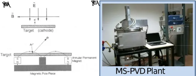
![Fig. 4.3 The FIB principle, from left to right: Imaging, Milling and Deposition. Source [52]](https://thumb-eu.123doks.com/thumbv2/123dokorg/2836444.4827/48.918.130.790.683.870/fig-fib-principle-right-imaging-milling-deposition-source.webp)
