UNIVERSITY
OF TRENTO
DEPARTMENT OF INFORMATION AND COMMUNICATION TECHNOLOGY
38050 Povo – Trento (Italy), Via Sommarive 14 http://www.dit.unitn.it
EXTRACTION OF PI-CALCULUS SPECIFICATIONS FROM UML SEQUENCE AND STATE DIAGRAMS
Katerina Korenblat and Corrado Priami
February 2003
http://www.omnys.it/degas
DEGAS IST-2001-32072
Design Environments for Global ApplicationS
Consortium: UNITN (I) University of Trento (Coordinator), IMM (DK) Institute of Mathematical Modelling - Technical University of Denmark, DIPISA (I) Dipartimento di Informatica - Universit`a di Pisa, UEDIN (UK) University of Edinburgh - MTCI (I) Motorola Technology Center Italy - OMNYS (I) Omnys Wireless Technology
Extraction of π-calculus specifications from
UML sequence and state diagrams
Author(s): Katerina Korenblat and Corrado Priami
Participant(s): UNITN
Workpackage: WP4 Extraction, Reflection and Integration
Document number: WP4-UNITN-I01-Int-001
Extraction of
π-calculus specifications from
UML sequence and state diagrams
∗Katerina Korenblat and Corrado Priami
Dipartimento di Informatica e Telecommunicazioni University of Trento - Povo, Italy
[email protected], [email protected]
Abstract
We propose an automatic translation of UML specifications made up of sequence and state diagrams into π-calculus processes. The central point of the proposed translation is the coherence of the two types of diagrams. An implicit result of the paper is also the definition of a formal semantics for UML sequence diagrams.
1
Introduction
The Unified Modeling Language (UML) [1] is a standard notation used to capture high-level design of software systems. It gives struc-tured, semi-formal, graphical methods for specification which are however not strong enough for verification and validation of sys-tems. UML provides the user with different kinds of diagrams, each of them is natural for a description of different aspects of a complex (software) system. In this paper we restrict our attention on specifi-cations including only sequence and state diagrams. Such a choice is often sufficient for specifying the behaviour of a whole system and can be considered as a first step in handling multi-diagram UML specifications.
To implement a formal analysis of a UML specification, we pro-pose to translate it to some formal notation. The target formalism of the translation that we select is process algebras [4]. Process algebras are foundational calculi used to describe the concurrent and distributed structure of systems. They are made up of a few operators such as: i) a.− that describes sequential composition of
∗This work is partially supported by the DEGAS (Design Environment fore Global
actions, ii) − | − that is the parallel composition of processes, iii) − + − that denotes a nondeterministic choice. We can view process algebras from different levels of abstraction. A common interpre-tation is seeing these calculi as specification languages that must be refined towards a real code. The theory of behavioral analysis developed for process algebras (see e.g., [4]) postulates that refined descriptions are still expressed in the same calculus but through different programs. Then, some relations (usually a bisimulation) are established between the two descriptions of the system to en-sure that an implementation behaves according to its specification. We are proposing here a different use of process algebras. We in-terpret these calculi as an intermediate language into which UML specifications can be translated. A state diagram based approach to translation from UML to process algebras was presented in [2] and [3]. In those works states are represented as processes and transi-tions are represented as actransi-tions along communication channels.
In this paper we focus on a sequence diagram based approach, where objects are considered as π-calculus [5] processes and mes-sages as communications among these processes. A state diagram of an object is used for choosing the feasible sequences of the mes-sages occurring in the sequence diagram. This is needed because sequence diagrams only show possible behaviour, thus exposing sam-ple computations. Note that an outcome of our proposal is also the definition of a formal semantics for UML sequence diagrams based on the structural operational semantics of the π-calculus.
We now briefly discuss the motivations for the present work. We rely on a standard Unified Modelling Language (UML) to ease for-mal methods into the software production process. The challanges we approach in this task are the definition of techniques to extract specifications into process calculi from the possibly excessive or in-complete information in the UML description. The final goal is to have a design environment in which the user interacts with UML only in order to perform formal analysis of his/her applications.
The paper is structured as follows. In section 2 there is a descrip-tion of those aspects of UML we are interested in. In secdescrip-tion 3 an overview of the π-calculus is presented. A translation from sequence diagrams to π-calculus is given in section 4. Finally, in section 5 we discuss the joint translation of sequence and state diagrams.
2
Brief UML description
UML is a semi-formal modelling language which is a standard for high-level specification of software systems. There are many dif-ferent types of UML diagrams which are used to specify difdif-ferent aspects of software systems. In this short presentation we focus on sequence and state diagrams.
A sequence diagram shows how objects interact with one an-other by representing examples of executions. A sequence diagram has two dimensions: the vertical dimension represents time and the horizontal one represents different objects. Objects can communi-cate by exchanging messages represented by arrows. To show dif-ferent kinds of communications the following variations of notation are considered in this paper.
• Stick arrowhead is used for synchronous communication. In the case of nested control flow the entire nested sequence have to be completed before the outer level sequence resume.
• Dashed arrow with stick arrowhead is used for returning mes-sage.
A message is labeled at least with the message name; one can also include arguments and a condition which acts as a guard for send-ing the message. Furthermore a message can be associated with an assignment that associates with the assigned variable the value returned after the message.
Messages can be combined in a branching construction which is shown by multiple arrows leaving a single point and means alterna-tive or concurrency of those messages depending of their conditions. A state diagram describes the sequences of states and transi-tions through which the modeled element can proceed during its lifetime as a reaction to discrete events. A state diagram is a graph that represents a state machine.
The formal operational semantics of a state diagram is defined in terms of a Kripke structure [6]. Given a sequence s1[t1i . . . [tnisn of
states (si) and transitions (ti) in the Kripke structure of a state
dia-gram S, we call a trace of S the sequence of transitions ht1, . . . , tni.
3
The π-Calculus
In this section we briefly recall the π-calculus [5], a model of con-current communicating processes providing the notion of naming.
Let N be a countable infinite set of names ranged over by a, b, . . . with N ∩{τ } = ∅. We also assume a set A of agent identifiers ranged over by A, A1, . . .. Processes (denoted by P, Q, R, . . . ∈ P) are built
from names according to the syntax
P ::= 0 | π.P | P + P | P |P | (νx)P | [x = y]P | A(y1, . . . , yn)
where π may be x(y) for input, xhyi for output (where x is the subject and y the object), ε for empty string, or τ for silent moves. Hereafter, the trailing 0 will be omitted.
The prefix π is the first atomic action that the process π.P can perform. The input prefix binds the name y in the prefixed pro-cess. Intuitively, some name y is received along the link named x. The output prefix does not bind the name y which is sent along x. The silent prefix τ denotes an action which is invisible to an external observer of the system. Summation denotes nondetermin-istic choice. The operator | describes parallel composition of pro-cesses. The operator (νx) acts as a static binder for the name x in the process P that it prefixes. In other words, x is a unique name in P which is different from all the external names. Finally, matching [x = y]P is an if-then operator: process P is activated if x = y. A(y1, . . . , yn) is the definition of constants (hereafter, ˜y
denotes y1, . . . , yn). Each agent identifier A has a unique defining
equation of the form A(y1, . . . , yn) = P , where the yi are distinct
and fn(P ) ⊆ {y1, . . . , yn} (see below for the definition of free names
fn).
A parallel composition of processes P1, . . . , Pnis written asQi=1...nPi.
For a set of names V = {v1, . . . vn} we use the notation (νV )P for
(νv1) . . . (νvn)P and (νv1, v2)P for (νv1)(νv2)P .
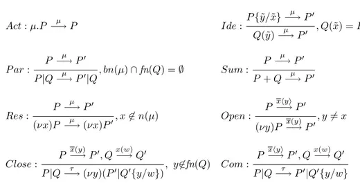
The late operational semantics for the π-calculus is defined in the SOS style, and the labels of the transitions are τ for silent actions, x(y) for input, xy for free output, and x(y) for bound output. We will use µ as a metavariable for the labels of transitions (it is distinct from π, the metavariable for prefixes, though it coincides in two cases). We recall the notion of free names fn(µ), bound names bn(µ),
and names n(µ) = fn(µ) ∪ bn(µ) of a label µ.
µ Kind fn(µ) bn(µ)
τ Silent ∅ ∅
xy Free Output {x, y} ∅
x(y), x(y) Input and Bound Output {x} {y}
Functions fn, bn and n are extended to processes in the obvious way. Below we assume that the structural congruence ≡ on processes is defined as the least congruence satisfying the following clauses:
• P and Q α-equivalent (they only differ in the choice of bound names) implies P ≡ Q,
• (P/≡, +, 0) and (P/≡, |, 0) are a commutative monoid,
• ε.P ≡ P , • [x = x]P ≡ P ,
• (νx)(νy)P ≡ (νy)(νx)P, (νx)(R | S) ≡ (νx)R | S if x 6∈ fn(S), (νx)(R | S) ≡ R | (νx)S if x 6∈ fn(R), and (νx)P ≡ P if x 6∈ fn(P ).
A variant of P −→ Q is a transition which only differs in that Pµ
and Q have been replaced by structurally congruent processes, and µ has been α-converted, where a name bound in µ includes Q in its scope.
We report the late transition system for the π-calculus in Tab. 1. The transition in the conclusion of each rule, as well as in the axiom, stands for all its variants.
4
Translation of Sequence Diagrams
In this section we restrict our attention to UML sequence diagrams. Note that the semantics of UML allows a message in a sequence diagram to be skipped. For simplicity in this section we consider the case of non-skipping messages as it is the common practice of designers (we will deal with skipping of messages later in the paper). Moreover we assume that names of messages are unique, otherwise we rename them before translation.
Act : µ.P −→ Pµ Ide : P {˜y/˜x} µ −→ P0 Q(˜y)−→ Pµ 0 , Q(˜x) = P P ar : P µ −→ P0 P |Q−→ Pµ 0|Q, bn(µ) ∩ fn(Q) = ∅ Sum : P −→ Pµ 0 P + Q−→ Pµ 0 Res : P µ −→ P0 (νx)P −→ (νx)Pµ 0, x 6∈ n(µ) Open : P xhyi−→ P0 (νy)P x(y)−→ P0, y 6= x Close : P x(y) −→ P0, Qx(w)−→ Q0
P |Q−→ (νy)(Pτ 0|Q0{y/w}), y6∈fn(Q) Com :
P xhyi−→ P0, Qx(w)−→ Q0 P |Q−→ Pτ 0|Q0{y/w}
Table 1: Late transition system for the π-calculus.
First we consider sequence diagrams without conditions on mes-sages. We will represent an object from a sequence diagram as a process in the π-calculus and compose all processes arising from the given sequence diagram via parallel composition.
A message between two objects is represented as a communi-cation between the corresponding processes. For each message we create a private channel in the π-calculus representation and trans-late the message as a synchronization on this channel. As far as sequence diagrams show how an object interacts with others, it is natural to consider an object as a sequence of sending and receiving of messages. To translate an object we produce sequentially for each of its sent/received message an input/output of a signal along the corresponding channel.
Given two objects connected by a message m in the UML model, we translate this message as an input on the channel m in the object receiving the message and an output on the same channel in the object sending the message (see Fig. 1).
Consider now a message with a condition.
The message is sent if its condition is satisfied, or it is skipped otherwise. Given a sending message [x]m, we obtain an output on the channel m prefixed by the matching [x = true] if the condition is satisfied, or a skipping of the message prefixed by the matching
[x = f alse] otherwise. For a receiving message [x]m we obtain an input on m or a skipping of it, depending on the value of x. For example, in Fig. 2 a simple sequence diagram with a single condition x is translated to a summation of two subprocesses representing two possible valuations of x.
Nested messages initialized by a message with a condition includ-ing its return will be discarded if the condition is not satisfied. We translate an explicit return of the message as a usual message with
the name returnhmessage namei. For example, we translate a message
[x]m with an explicit return (Fig. 3) as a sequence of messages [x]m
followed by returnm.
A branching of several messages is translated as a parallel com-position of these messages synchronized before continuation because all of branched messages have to be delivered. In more details, for a sending object we introduce an input on the special channel syn after any branched messages. Then we construct a continuation pro-cess that is the translation of the remaining messages prefixed by sending of a syn signal for any message in the branching construc-tion. Finally, we compose the translation of the branching structure and the continuation process by parallel composition. In the receiv-ing process we have a parallel composition of branched messages and continuation without synchronization. We use the syn channel to force the continuation process starting after the delivery of all the branching messages. We illustrate our translation on a simple sequence diagram presenting two parallel messages followed by a
re-ply (see Fig. 4). We use a channel syn to force m3 occurring after
m1 and m2. Note that if the branching messages have alternative
conditions
An assignment construction is generally used for binding an iden-tifier that stores the return value of a message. It can be translated as an explicit return of a message which transfer not a signal but a required variable (see Fig. 5). In other words, we use a real commu-nication rather than a simple synchronization.
We now formally define a translation function from UML se-quence diagrams to the π-calculus. Given a message m, we define a set of nested messages nest(m) in a case of an explicit return as a set of messages that become enable by the sending of m before the return of m (including the return), oras an empty set, otherwise.
=⇒ (νm)(m | m)
Figure 1: Translation of a message.
=⇒ (νm1, m2)(([x = true] m1. m2| m1. m2) + ([x = f alse] m2| m2))
Figure 2: Translation of a condition.
messages Mes and a set of conditions C. Let ρ : C ∪ {Λ} → Bool be an evaluation function of conditions that returns true for the
special condition Λ. Given a message m, we define cm as a condition
corresponding to m, or as Λ if there is no condition on m. Given an object O and a message m related with O, we define the function
trρ : O × Mes → P1 as trρ(O, m) =
[cm = true] m, if O sends m and ρ(cm) = true;
dcm = f alseeε, if O sends m and ρ(cm) = f alse;
m, if O sends m and cm = Λ;
m, if O receives m and ρ(cm) = true;
ε, if (O receives m and ρ(cm) = f alse)
or (∃m0 | m ∈ nest(m0)
and ρ(cm0
) = f alse).
Fix an evaluation ρ and an object O defined by a sequence of set
of sent/ received messages MO = hM
0, M1, . . . , Mni, where any set
Mi = {m1i, . . . , m ki
i } represent branching messages and m
j
i ∈ Mes
for each j ∈ {1 . . . ki} and i ∈ {1 . . . n}. We define the translation
function seqρ : O × Mes∗ → P as follows:
seqρ(O, h i) = 0, and
1By abuse of notation we use here the metavariable for processes P to denote prefixes
=⇒ (νm, returnm)([x = true]m. returnm| m. returnm)
Figure 3: Translation of a return.
(νm1, m2, m3, syn) (m1. syn | =⇒ m2. syn | syn. syn. m3| m1| m2| m3)
Figure 4: Translation of a branching construction.
seqρ(O, hMi, . . . , Mni) = =
trρ(O, m1i).seqρ(O, hMi+1, . . . , Mni), if ki = 1
(Qj=1...kitrρ(O, m
j
i).seqρ(O, hMi+1, . . . , Mni |nest(mj i)).syn
Mi) |
| synMi. . . . .synMi
| {z }
ki
.seqρ(O, rest(hMi, . . . , Mni)), if ki > 1
where rest(hMi, . . . , Mni) is a subsequence of hMi, . . . , Mni starting
after returns of all messages from Mi.
Eventually, for a fixed evaluation ρ we obtain Pρ =Q
O∈Sseqρ(O, MO).
And the overall translation of Sq is P = (νV )(Pρ∈C∪{Λ}×BoolPρ),
where V = {v | v ∈ MO∨ v = synMi}.
In the proposed translation we always compare names with con-stant values. Name matching can be implemented as presented in Fig. 6. The idea of such strong translation is to construct an addi-tional subprocess for the valuation of the variable.
As final remarks, we give some notes for simplifying the result of the translation.
• Repeating conditions. We leave in a process only the first in-stance of a repeating condition.
• Empty branched subprocesses. In a translation of branching construction because of the false value of a condition we can ob-tain a parallel subprocess conob-taining only conditions and receiv-ing of a synchronizreceiv-ing message. Such processes are nonessen-tial and can be skipped together with a corresponding sending
=⇒ (νm, returnm, x)(m. returnm(x) | m. returnmhxi)
Figure 5: Translation of an assignment.
PO1 = m1. returnm1(x). [x = true]m2
=⇒ PO2 = m1. val(x). returnm1hxi. m2
V al = valhtruei + valhf alsei P = PO1 | PO2 | V al
Figure 6: Translation of a condition using name matching.
of the synchronizing message. In the case of a single active branched message we can translate it as usual sequence mes-sage. For an example see the end of the following subsection.
4.1 An Example
To illustrate our translation consider the sequence diagram in Fig. 7 representing a slight variant of the Phone system in [3]. In this
example we have two conditions c1 = [busy] and c2 = [not busy].
Thus we obtain two possible valuations ρ1 : ρ1(c1) = true, ρ1(c2) =
f alse and ρ2 : ρ2(c1) = f alse, ρ2(c2) = true.
The result of the translation is shown below.
Callerρ1= lif t. dial tone. number. connect tone. busy tone. hangs up
Callerρ2 = lif t. dial tone. number. connect tone. ring tone. talking
1. talking2.
disconnect. hangs up
P honeρ1= (νsyn1)lif t. dial tone. number. (connect tone. syn1| connect.
returnconnect(busy). syn
1| syn1. syn1.[busy = true]busy tone. hangs up)
P honeρ2= (νsyn
1, syn2)lif t. dial tone. number. (connect tone. syn1| connect.
returnconnect(busy). syn
1| syn1. syn1. Calling)
Calling= [busy = f alse]ring tone. syn2| [busy = f alse]call. answer. returncall.
syn2| syn2. syn2. disconnect. hangs up
Receiverρ1= connect. returnconnect
hbusyi. [busy = true]ε Receiverρ2= connect. returnconnect
hbusyi. [busy = f alse]call. answer. talking1.
talking2. returncall
System= (νV )(P honeρ1 | Receiverρ1 | Callerρ1) + (P honeρ2| Receiverρ2| Callerρ2)
Figure 7: Sequence diagram of the Phone system.
Now we illustrate the simplification technique of empty branched
subprocesses described in the previous section. In P honeρ1 we can
translate the branching construction {busy tone, ring tone, call} as a single message busy tone because conditions on two other messages
are false on a valuation ρ1, and we obtain its translation [busy =
true]busy tone instead of [busy = true]syn2 | [busy = true]syn2 |
[busy = true]busy tone.syn2 | syn2.syn2.syn2 as it would be done
in the general case.
5
Joint Translation of Sequence and State
Dia-grams
Each type of UML diagrams has its own most natural way of trans-lation to the π-calculus. To translate a whole system composed of different diagrams we choose a driving type of diagrams (here a sequence diagram), and we take Necessary additional informa-tion about the system from other types of diagrams (here state
di-Figure 8: State diagram of the object Phone of the Phone system.
agrams). For a joint translation of sequence and state diagrams we have two different approaches which are distinguished in the choice of the driving type of diagrams:
• Sequence diagram based translation. According to our transla-tion, each valuation is considered and translated separately so that the obtained π-calculus representation is a summation of subprocesses for all possible valuations. Additional information from state diagrams helps to determine feasible computations. The problem here is to represent more detailed information from state diagrams because it is not understandable how to translate internal actions of a state diagram not represented in the sequence diagram. It is possible to ignore this detailisation and obtain a translation at a communication level.
• State diagram based translation. A state diagram (for each ob-ject) is translated as a process parameterized by state name and representing a transition from state to state. Additional infor-mation from a sequence diagram is necessary for composing the processes corresponding to different state diagrams. Such ap-proach was used in [2] for producing translation to Performance Evaluation Process Algebra (PEPA).
The last approach requiresa very detailed description of each ob-ject of a system. However, sometimes we would prefer to have a high-level specification which does not contain such a detailed
spec-ification of all objects. This is why we prefer a sequence diagram based approach.
5.1 Sequence Diagram Based Translation
In the previous section we considered the case of nonskipped mes-sages. However, in a general case a message in a sequence diagram can be skipped. It can be useful, for example, to present several use cases in one sequence diagram. If we consider a separate sequence diagram in this paradigm we obtain all possible subsequences of a given sequence of messages. So, we can see only an order of mes-sages but have no information which message have to be skipped in an allowed behaviour. To illustrate such a situation we add to the Phone system on Fig. 7 a message timeout tone from Caller to P hone between messages dial tone and number. It can be inter-preted as follows. If a Caller does not dial a number, after some waiting period it receives a timeout tone and finishes the call. After the timeout tone, the Caller cannot dial a number, but a sequence diagram does not give us such information, and we have a sequence of messages
h..dial tone, timeout tone, number..i besides the correct sequences
h..dial tone, timeout tone, hangs upi and h..dial tone, number..i. To consider only correct sequences of messages we need some additional information which can be taken from other types of dia-grams. For example, such information can be obtained from state diagrams which describe behaviour of objects.
UML gives instruments for the description of a system but it does not guarantee completeness and accordance of the model. So to make a correct translation we have to formalize our assumptions about a system. We consider a system made up of one sequence diagram and a number of state diagrams (one for each object of the sequence diagram) with the following requirements:
• Messages in a sequence diagram have unique names. It is nec-essary for correct correspondence between messages in the se-quence diagram and transitions in the state diagrams.
• A name of a transition corresponding to a transmission of a message coincides with a name of this message.
• Each communication is presented in the state diagram of an object explicitly.
The behavior of a single object is described by a state diagram and communication between objects is described by a sequence diagram. Here we fix the simplest for translation assumption about state di-agrams. In alternative, we can assume, for example, that a message absent in the state diagram can be skipped only with the immedi-ately previous message.
Note that a state diagram can include more detailed information than a corresponding sequence diagram. But in this translation we use state diagrams only for additional information about available sequences of messages. So internal actions of a state diagram are nonessential to our translation.
The first step of the translation is to rename transitions in such a way that there are no two transitions with the same name available in one state. For this purpose we enumerate such transitions by adding of superscripts to their names.
Given a state diagram S, we define an external trace of S as a restriction of a trace of S on a set of transitions corresponding to messages. A set of external traces of S is denoted by T (S).
Now we modify the translation of sequence diagrams proposed in section 4 by taking information from state diagrams to single out correct execution sequences. The difference from the original
algorithm is the definition of the function seqρ. For readability
we define seqρ assuming no branching of messages. Hereafter, we
write head for a trace in a state diagram that reaches the current state. Fix an evaluation ρ and an object O with a sequence of
sent/received messages hm1, . . . , mni, and a state diagram SO.
Be-ginning from seqρ(O, ∅, hm1, . . . , mni) we calculate the translation
function seqρ : O × T (SO) × Mes∗ → P as follows:
seqρ(O, γ, h i) = 0 where γ ∈ T (SO), and
seqρ(O, head, hmi, . . . , mni) =
X
{j |head ◦ mji∈T (SO)}
trρ(O, mi).seqρ(O, head◦mji, hmi+1, . . . , mni)+skip,
there exists a maximal trace head ◦ t for some t 6= mk or there exists
a trace head ◦ mk for some k > i.
Let us illustrate this approach with the Phone System which was already considered in section 4. Now we represent it by the sequence diagram (Fig. 7) and the state diagram for the object Phone (Fig. 8).
An assumption about skipping of messages intuitively means that the Caller can hang up after any of his actions. The result of the
translation of an object P hone on the valuation ρ1 is:
P honeρ1 = lif t. dial tone. (hangs up+number. hangs up+number.
(connect tone. syn1 | connect.returnconnect(busy). syn1 |
syn1.
syn1. [busy = true]busy tone. hangs up))
A separate problem is a translation of a part-described system. If one of the objects in a sequence diagram related by the message is not described by a state diagram, we can extract information from an existing state diagram. To illustrate this moment let us consider the translation of the object Caller from the Phone System based on the sequence diagram (Fig. 7) and the state diagram for the object
Phone(Fig. 8):
Callerρ1 = lif t. dial tone. (hangs up+number. hangs up+number.
connect tone. busy tone. hangs up)
Here we suppose that for the receiving of a message number there are three cases: ”ignore the message and finish”, ”finish after the message” and ”continue after the message”, then we have the same cases for the sending of this message.
6
Conclusion
In this paper we discussed a translation to the π-calculus of non ho-mogeneous UML specifications. We proposed an approach based on sequence and state diagrams. As a prolongation of this investigation it would be interesting to extract this translation for other types of UML diagrams to present more complex software systems. Further-more, we are currently implementing our translation and integrating it with open-source UML tools.
This paper is a first step towards the use of formal methods in the current practice of software development. The main contribution of
our extraction of process algebra specifications from UML diagrams is the hiding of formal details from the designers.
Finally, we have implicitly defined formal semantics of UML sequence diagrams based on the operational semantics of the π-calculus.
References
[1] G. Booch, J. Rumbaugh and I. Jacobson. UML notation guide, version 1.1. Rational Software Corporation, Santa Clara, CA, 1997.
[2] C. Canevet, S. Gilmore, J. Hillston, and P. Stevens. Perfor-mance modelling with UML and stochastic process algebras. To appear in Proceedings of UK PEW, 2002.
[3] Y. Dumond, D. Girardet and F. Oquendo. A Relationship Between Sequence and Statechart Diagrams. Proc. <<UML> >2000, York, UK, 2000.
[4] R. Milner. A Calculus of Communicating Systems. Prentice-Hall, 1989.
[5] R. Milner, J. Parrow and D. Walker. A calculus of mobile pro-cesses. Inform. and Comput. 100 (1), 1992.
[6] D. Latella, I. Majzik, M. Massink. Toward a formal operational semantics of UML statechart diagrams. Proc. FMOODS’99, Florence, Italy, 1999.