UNIVERSITA’ DI PISA
DIPARTIMENTO DI INGEGNERIA
DELL’ENERGIA, DEI SISTEMI, DEL TERRITORIO
E DELLE COSTRUZIONI
Corso di Laurea Specialistica in
Ingegneria Idraulica, dei Trasporti e del Territorio
– indirizzo Trasporti e Territorio –
TESI DI LAUREA
A
NALYSIS OF TRACK PERFORMANCE OVER
INNOVATIVE TRACKBED TREATMENTS IN
TRANSITION ZONES
Relatori:
Candidato:
Prof. Ing. Massimo Losa
Ramon Bianchi
Dott. Matthew Brough
Dott. Phil Sharpe
”Virtute duce, comite fortuna” Alla mia famiglia, in particolare a super mamma Helena Al quasi fratello e compagno di viaggi Ivan Alla quasi sorella Valentina Ai compagni di studio Chiara e Tommaso Ad Alessandro A chi non c’è più
SUMMARY
INTRODUCTION ... 1
1 TRANSITION ZONES ... 4
1.1 Background ... 6
1.2 Definitions ... 7
1.3 Track Transition Literature Review ... 9
1.3.1 Problem Definition ... 9
1.4 Track Stiffness and Modulus ... 11
1.5 Transition problems Test Results ... 12
1.5.1 Track Geometry Degradation (Differential Settlement) ... 12
1.5.2 Track Modulus ... 14
1.6 Discussion of Transition Remedies ... 15
1.6.1 Kerr and Moroney (1993) Transition Categories ... 15
1.6.2 Increasing Track stiffness with Long Ties ... 15
1.6.3 MARTA Variable Length Timber-Tie Transitions ... 16
1.6.4 HMA Underlayment ... 17
1.6.5 Increasing Approach Stiffness at Grate Crossing ... 17
1.6.6 Additional Rails ... 18
1.6.7 Concrete Bridge Approach Slabs ... 18
1.6.8 Slab Track Approach ... 19
1.6.9 Stone Columns ... 20
1.6.10 Piles and Micro Piles ... 21
1.6.11 Geogrid Reinforcement ... 24
1.6.11.1 BASIC PRINCIPLES OF REINFORCED SOIL ... 24
1.6.11.2 POLYMERIC REINFORCEMENT ... 26
1.6.11.3 GEOSYNTHETICS IN ROADWAYS AND RAILWAYS BASES ... 29
1.6.12 XiTRACK Polymer Reinforcement ... 34
1.6.13 Other Geotechnical Considerations ... 36
1.6.14 Rail Seat Pads on Open Deck Bridges and Direct-Fixation Structures ... 37
1.6.15 Rubber Tie Mats ... 37
1.6.16 Reducing Track Stiffness on Ballast Deck Bridges ... 37
1.7 Summary of Remedies ... 38
1.8 Analysis of Representative Track Transition Designs ... 39
2 TRACK GEOMETRY AND TRACK QUALITY ... 41
2.1 Track Settlement ... 41 Track Geometry ... 42 2.2.1 Definitions ... 43 2.2.1.1 LAYOUT ... 43 2.2.1.2 TRACK GAUGE ... 43 2.2.1.3 TRANSVERSE ELEVATION ... 43 2.2.1.4 LONGITUDINAL ELEVATION ... 44
2.2.1.6 ALIGNMENT ... 47
2.2.2 Filtering of Measured Track Geometry ... 47
2.3 Standard Deviation ... 49
2.4 Measurement of Track Geometry ... 49
2.4.1 Datum Lasers ... 49
2.4.2 FROG Lasers ... 50
2.4.3 Track Geometry Cars and Track Recording Cars ... 51
2.4.3.1 PARAMETERS MEASURED ... 52
2.4.3.2 NEW MEASUREMENT TRAIN (NMT) ... 53
2.5 Track Quality ... 55
2.5.1 Track Quality Standards ... 55
2.5.2 Track Recording Cars ... 56
2.5.3 Falling Weight Deflectometer ... 56
2.5.4 Inherent Track Quality ... 61
2.5.5 Conclusions Regarding Track Quality ... 61
2.6 Inherent Track Shape ... 62
2.6.1 Persistence of Inherent Track Shape ... 62
2.6.2 Influence Rail Shape and Ballast Surface Profile ... 63
2.6.2.1 RAIL SHAPE ... 64
2.6.2.2 TOP BALLAST SURFACE PROFILE ... 65
2.7 Improving the Inherent Shape of Track ... 66
2.7.1 Rail Straightening ... 66
2.7.2 Tamping ... 66
2.7.2.1 LIFT/SETTLEMENT RELATIONSHIP ... 66
2.7.2.2 HIGH LIFT DESIGN TAMPING ... 68
2.8 Benefits from Good Inherent Quality Track ... 69
2.8.1 General Considerations ... 69
2.8.2 Conclusions Regarding Inherent Track Quality ... 70
2.9 Achieved Good Inherent Quality Track ... 70
2.10 Summarizing ... 72
3 RESEARCH DESCRIPTION ... 73
3.1 Analysis of the most widely used Methods of Reinforcement adopted in the UK ... 74
3.2 Study of the Database of Final Reports about all the Sites Investigated by ScottWilson/URS 74 3.3 Review of the List of Sites of National Rail Network interested from a Renewal ... 75
3.4 The GPR graph and the Code Quality graph (CCQ) ... 76
3.5 Search of Raw Data of all Selected Sites ... 78
3.5.1 Records ... 78
3.5.1 Data ... 79
3.6 Identification of the 13 Sites and Elaboration of Raw Data ... 80
3.6.1 Sites ... 80
3.6.1.1 GEOGRID ... 81
3.6.1.2 XITRACK POLYMER ... 84
3.6.1.3 MICRO-PILES ... 85
3.6.2 Raw Data ... 85
3.6.3 Example of Site Studied (CALVERLEY)... 86
3.6.3.1 SITE DETAILS ... 86
3.6.3.2 FINAL REPORTS OF SCOTTWILSON ... 86
3.6.3.3 CCQ CHART ... 87
3.6.3.4 HSTRC DATA PROCESSING ... 91
3.6.3.5 GEOMETRY PLOT (raw data of TQ, SD and GPR) ... 93
3.7 Analysis of all the Data and Parameters ... 95
3.7.1 Data ... 95
3.7.2 Parameters ... 97
3.7.3 Comparison between data and parameters ... 99
3.7.3.1 Mean values of TQ, SD and RD on the line and on the transition zone ... 99
3.7.3.2 Variable values of TQ, SD and RD on the line ... 99
3.7.4 TEMPLATES A and B ... 100
3.7.4.2 TEMPLATE B ... 101
3.8 Conclusions ... 103
4 RESULTS AND ANALYSIS ... 103
4.1 Results: TEMPLATE A and TEMPLATE B ... 103
4.2 Analysis of Results ... 132
4.2.1 Comments ... 134
5 CONCLUSIONS ... 139
INTRODUCTION
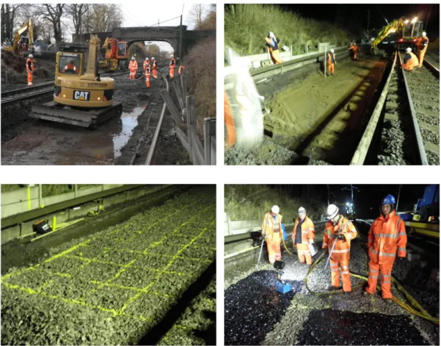
Transitions between different track support conditions can pose major problems for railways. These zones are located along tracks with different support stiffness, for example at the transition between soft soil and settlement free zones, or at the run on/off to structures such as box culverts or bridges. Problems with transitions on existing lines can cause poor track quality and subsequent excessive maintenance requirements or potential issues at structures due to increased dynamic interaction. Problems can be exacerbated by fluctuating environmental conditions and increased linespeeds. This dissertation presents a case study of 13 sites in the UK, and analyses existing data sets to better understand the causes, frequency and nature of deterioration. Operational transition sites and sites planned for remediation have been identified to better understand the performance of the various designs constructed. Transition solutions used comprise three different treatments. In the last few years, the National Railtrack commissioned Scott Wilson Railways (SWR) in conjunction with Scott Wilson Pavement Engineering (SWPE), of which many works of investigation were on different sites: the idea was to create a desk study to analyse all the sites investigated to find transition zones where the use of different methods of reinforcement was recommended. The most widespread type of reinforcement was the one that uses the geogrid, in line with the tendency most used in the UK in recent years. However sites were found in which the techniques of the polymers and of micropiles were recommended. The three treatments studied are characterised by the following features.
a) GEOGRID REINFORCEMENT
Geogrid is manufactured from a unique process of extrusion and then bi-oriented to enhance his tensile properties. It is manufactured from polypropylene and produced with high tensile stiffness in both longitudinal and transverse directions allowing load to be resisted at very low strains. It is designed specifically with large rigid square apertures having an optimum mesh size of 65 mm therefore maximising mechanical interlock with the railway ballast. Bi-oriented geogrid provides an effective way of reducing the rate of ballast settlement over soft subgrades. Independent trials have confirmed that it is the stiffness and the size of the geogrid apertures that determine the structural performance of pavements. Being chemically inert and having a high tensile strength and modulus, it is specifically produced for the reinforcement of soil.
Soil and aggregate interlock within the geogrid openings, which, confine the soil and limit its relative displacements and increase the soil's shear stress resistance. Soil compaction produces an interlock between the soil and both faces of the geogrid layer, thus it's necessary to reach a higher level of tension in order to overcome such an interlock and give rise to movement. The composite soil/geogrid structure therefore, acts as if it had an intrinsic tensile strength. The insertion of the geogrid thus produces a type of cohesion within materials that would be otherwise non-cohesive. The soil/geogrid structure integrates the fill soil high compressive strength with the geogrid's tensile strength, thus creating a material having greater rigidity and stability than the aggregate alone.
b) POLYMER REINFORCEMENT (XiTRACK)
This is a method of reinforcing and stabilising railway track using advanced polymer-based technology. Through special mixing equipment, a two component rapidly reating polymer is applied in a controlled distribution to the ballast geo-matrix. As the polymer penetrates the ballast it forms a 3-Dimensional reinforcing cage, or GeoComposite, which allows the track to move in a designed manner. The GeoComposite permits the discrete nature of the ballast particles to be transformed into a highly resilient continuous flexible geo-pavement providing increased horizontal and vertical track stability. Flexibility and ductility in the track are maintained by the visco-elastic nature of the polymers. The engineering properties of the polymer are fully designable which allows differing levels of support strength, stiffness and damping to be achieved in the GeoComposite to ensure that the track retains desirable energy absorption properties. The polymer application is controlled in a designed way by the polymer properties, loading pattern and distribution on track. The polymers tested are rapid-curing and treatment is usually complete within a few hours and track can usually be re-opened at line-speed. The process still allows conventional methods of track maintenance to be used post-treatment (should the need arise) and drainage within the track is still fully maintained. There are patented techniques that have been specifically developed to meet the demands of modern ballasted track with increasing train axle weight, line-speed and track usage coupled with reduced maintenance schedules. The treatment can be used as a maintenance tool or during renewal to reduce track alignment problems which usually result in degraded ballast. Ballast performance is restored in a single treatment.
c) MICRO-PILES
This method of reinforcing railway track uses piles: these are 300 mm (12 inches) or less in diameter, employ a single rod or pipe and are grouted in place with Neat cement (water and Portland cement). A few " test" micropiles are generally installed and tested at the site to verify the capacity and installation technique prior to production micro piles. The production micro piles are generally not tested, but can be economically tested in tension (at half the compression load, or as per engineers recommendation).
They were invented in Italy (first known as PaliRadici or Root piles). Micropiles found quick application in underpinning historical landmarks, but now compete for use with conventional larger diameter piles systems. Micropiles can replace conventional piles under most circumstances, and are especially economical where there is difficult ground conditions (caving, ravelling or rocky ground conditions) or where there is limited or difficult access or work space, like inside buildings for earthquake upgrades. They are installed much like tiebacks or soil nails, using rotary or percussion drilling rigs. Because of their smaller size, a wide variety of drilling techniques can be employed more economically, which makes their use so attractive: flight auger, tri-cone, percussion rod, down-the-hole-hammer, casing with auger, hollow grouting drill (Titan), percussion rod etc. Micropiles are finding ever greater acceptance with engineers and designers who are replacing traditional piles with micropiles to the benefit of the owners.
By analysing the cases in which the 3 treatments introduced before were successful or not, it was possible to obtain important information about the behavior of different transition zones and on the treatment used.
The aim of this thesis is to determine a ranking of the different methods of reinforcement used in the transition zones and to provide guidelines to help the choice of the most effective treatment in relation to the specific characteristics of the site
1
TRANSITION ZONES
In rail transit systems, at-grade ballasted track frequently changes to a non ballasted track configuration or to ballasted track on a structure. The abrupt change in track support that can occur at these locations is often associated with accelerated rates of track geometry and component degradation, high maintenance demand, and poor ride quality. Accordingly, a number of techniques have been proposed to improve track performance by providing a transition to smooth the stiffness interface between the dissimilar track types. A review of typical transition designs, as found in the existing literature, and analyses of representative designs are the subjects of this digest.
A review of published material dealing with track transition problems and solutions was undertaken as the initial phase of the study. The literature indicated that transitions were designed to (1) equalize the stiffness and rail deflection of the ballasted and nonballasted tracks, usually by controlling the resilience of the rail on the nonballasted track, or (2) provide a gradual increase in the stiffness of the ballasted track to match that of the nonballasted track. Several designs seek to increase the stiffness of the ballasted track by placing a structural element, such as concrete slabs or an asphalt pavement layer, between the track granular layer (ballast/subballast layers) and the subgrade. These structural layers are generally tapered or stepped to allow a gradual increase, or ramping up, of the stiffness within about 20 ft of the nonballasted track interface. Other designs seek to match the stiffness/deflection characteristics of the nonballasted track to the ballasted approach track using elastomeric pads at the rail seat or beneath the tie plates. This technique requires measurement of the ballasted approach track to determine its nominal stiffness and track modulus values and testing of the rail/tie pad stiffness characteristics to ensure that the pad stiffness matches the approach track modulus at the appropriate wheel loading. Elastomeric materials have also been placed on the bottoms of ties installed on ballast deck bridges to equalize the
stiffness/deflection of the bridge and approach tracks. The following performance
improvements were noted in case studies from the literature review:
Use of longer ties and a concrete approach slab by the Metropolitan Atlanta Rapid Transit Authority (MARTA) to transition from ballasted at-grade track to direct-fixation structures.
Transition from at-grade ballasted track to a direct-fixation structure on a commuter/intercity passenger service railway in the United Kingdom using an approach slab along with vertically adjustable direct-fixation fasteners to allow design tamping of the ballasted approach track.
Installation of stone columns to strengthen and improve the drainage of a weak bridge approach subgrade on a Union Pacific main line.
Use of a transition grade crossing system designed to smooth the track modulus across the approach to a highway crossing and reduce impact rail loads at the crossing on New Jersey Transit‘s Atlantic City line.
Installation of tie pads on open wood-tie bridge decks having stiffness/resiliency characteristics designed to match the track modulus of the approach track on Amtrak‘s northeast corridor (NEC) and on a Norfolk Southern mainline with freight/intercity passenger service.
Reducing the track modulus on a Union Pacific ballast deck bridge by replacing the existing concrete deck ties with composite (plastic) ties or with concrete ties with a rubber pad cast into the tie bottom.
The importance of following geotechnical best practices regarding soil selection, compaction, and drainage of the approach subgrade was also discussed in a number of papers, especially highway research papers. A properly designed and constructed subgrade will have a nominal stiffness adequate for the applied load environment, will tend to perform consistently through wet and dry cycles, and will not be prone to differential settlement. These attributes make it easier to match the vertical response of the at-grade track and the track on a structure. It should be made clear that much of the literature reviewed was based on research performed on freight and intercity passenger tracks. There was not much literature generated from transit research.
Although the higher wheel loads and speeds of freight/intercity rail traffic create more intense track transition problems than rail transit, the basic track performance issues are
similar. Therefore, the experiences and results of research projects involving freight and
intercity passenger tracks are considered applicable to the transit environment.
Following the literature review, a number of representative track transition designs were analised using the GEOTRACK computer model.
GEOTRACK is a well-established and validated model that predicts a quasi-static response of the track to an applied vertical wheel load.
The analysis produced track modulus and vertical rail deflection values for a variety of track configurations: wood and concrete ties on low-, average-, and high-stiffness subgrades; at-grade track with concrete approach slabs and hot mix asphalt (HMA) underlayment; direct-fixation track with typical fastener pad vertical stiffness values; open deck bridges with wood ties; and ballast deck bridges with concrete ties.
Three wheel loads considered to be representative of the rail transit environment were analised: 12,000, 15,000, and 22,500 lb. The 12,000-lb load was intended to represent light rail operations, the 15,000-lb load is the static weight of a Metro North cab car with full seated passenger load (Kentner et al.1994, p. 270), and the 22,500-lb wheel load represents the Metro North static wheel load plus a 50% dynamic factor.
Results of the GEOTRACK analysis were as follows:
Matching the rail deflection on direct-fixation track to the deflection of the at-grade ballasted track, through careful design and specification of the direct-fixation fastener vertical stiffness, provides the best possibility for an effective and seamless transition between the two track configurations. However, ballasted track on low-stiffness subgrades also requires strengthening with either a concrete approach slab or HMA underlayment to match the direct-fixation track. Otherwise, the pad stiffness of the direct-fixation track would need to be unreasonably low.
A concrete approach slab placed between the ballast and subballast layers was the most effective technique for increasing ballasted track stiffness. HMA underlayment installed between the ballast and subgrade also produced benefits to low-strength track, but it was not as effective as concrete in increasing the stiffness of track on very low-stiffness subgrades.
Increasing the subgrade stiffness reduced the differences between concrete slab and HMA layer thicknesses.
Placing additional rails on the ties of the ballasted track to increase the stiffness of the track panel had modest benefits for low-stiffness subgrades. This condition often exists when bridge guard rails extend past the abutment onto the approach track.
Other changes to the track superstructure, such as reduced tie spacing, installation of longer ties, or installation of ties with larger cross sections had an insignificant effect on track modulus or rail deflections and, therefore, would not be especially effective transition designs.
1.1
Background
The metropolitan environments in which rail transit systems operate require the placement track not only in at-grade ballasted configurations, but also on bridges and elevated structures and in tunnels and street pavements. Locations where the at-grade ballasted track changes to a structure are often associated with accelerated rates of geometry and component degradation, high maintenance demand, and poor ride quality. In addition to deterioration of the track surface, alignment, and cross level, component problems can include exposed tie ends and reduced crib ballast from ballast migration, tie skewing and bunching, cracked concrete ties, accelerated plate cutting of wood ties, gage widening and loss of rail cant, deterioration of ballast from pumping and frequent tamping, and accelerated rail surface fatigue. The track interface at bridge abutments, grade crossings, slab/embedded track, and turnouts/rail crossings are potential problem areas, and it is generally recognized that effective transition designs may be required to optimize track performance at these locations. This digest presents the results and conclusions of an investigation into track transition designs. The investigation included a review of available literature from the railway industry and an analysis of designs thought to be representative of, and applicable to, the rail transit environment.
1.2
Definitions
Definitions for terms used throughout this digest are listed below.
Approach Slab—A reinforced concrete slab installed as a structural element in the
track substructure to increase the stiffness/modulus of the track. Most slabs are reinforced concrete and are designed either with a taper to gradually increase the stiffness over an approach distance of about 20 ft, or are uniform in thickness but placed at an angle with tapering of the ballast depth to achieve the same ramping effect.
At Grade—Track that is constructed on a prepared soil subgrade foundation.
Ballasted/Nonballasted Track—Ballasted track has a layer of aggregate between the
ties and the subgrade to distribute the applied wheel loads to the underlying layers; provide vertical, lateral, and longitudinal resistance to track panel movement; to drain moisture away from the ties; and to facilitate surfacing and lining of the track. Ballasted track is usually at grade, but it may be located on a structure (as in the case of ballast deck bridges). Nonballasted track designs vary, but, in the context of this digest, nonballasted track will be considered to be a directfixation track form.
Damping—The capacity to attenuate, diminish, and/or control oscillations or
deflections of an element of a system expressed as a unit of force that is dissipated per unit of distance and unit of time (lb/in./sec). Track damping is provided primarily by the resilience of rail seat and tie pads, by the resilience of the ballast layer, and by the friction between ties and ballast.
Track that is highly resilient has more damping than track that is less resilient.
Deep Pile Foundation—Foundations of aerial structure that are driven to bedrock. Design Tamping—A track surfacing technique developed in the United Kingdom in
which the track is over-lifted to compensate for the rapid rate of initial settlement.
Direct-Fixation Track—Nonballasted track in which the rail is mounted directly to a
concrete base—such as the deck of an aerial structure, a tunnel invert, or an at-grade slab—with a direct-fixation fastening system.
Elastomer—Polymer materials having the elastic properties of natural rubber.
Fastener Stiffness—The combined stiffness, expressed as the unit of applied force per
unit of deflection (lb/in.), of the fastening system and the tie at a specific applied load. For wood-tie track with steel-tie plates and no tie pads, the fastener stiffness is basically the compressibility of the wood.
Fastener stiffness of concrete-tie track is primarily the stiffness of the rail seat pad and pads on the tie bottom, if used. The stiffness of concrete-tie pads can vary between 300 and 2,000 kip/in. Fastener stiffness on direct-fixation track consists of the resilience of the elastomeric elements of the fastening system. Typical direct-fixation track fastener stiffness values are between 100 and 300 kip/in.
GEOTRACK Model—A computer model that represents the track as a multilayered
elastic structure and predicts the quasi-static response of the track to an applied wheel load. Input parameters include rail, tie, and substructure layer definitions as well as wheel load. Output parameters include rail deflections, track modulus, tie/ballast/subgrade pressures, and tie bending moments.
Reference is made to GEOTRACK several times in this digest‘s literature review (see ―Track Transition Literature Review‖) and is the basis of the analysis described in the section titled ―Analysis of Representative Track Transition Designs.‖ A more detailed description of GEOTRACK is also included in this section.
Hot Mix Asphalt (HMA) Underlayment—A layer of asphalt pavement that is
installed in ballasted track as a structural element in the substructure to increase the bearing capacity of the subgrade. Typical HMA layer thickness varies between 8 and 12 in. and can be installed between the ballast and subballast layers or directly on the subgrade in lieu of a granular subballast layer. HMA is a mixture of aggregate and bitumen, and its stiffness properties can be designed by varying the ratio of the constituents and the aggregate particle size distribution. Recommended use of HMA in the rail transit environment is available online from the Asphalt Institute.
Resilient Modulus (Er)—A geotechnical parameter that is expressed as a unit of force
per unit of area (ksi) and is used to define the elastic response of a soil to load. In the context of this digest, Er can be thought of as being equivalent to the modulus of elasticity. Typical values range from 2 ksi for a lowstrength soil, such as a high-plasticity clay, to 20 ksi for granular soil that has been placed at optimum density. Er is also used to describe the resilient behavior of aggregate materials such as ballast and pavements.
Track Stiffness/Track Modulus—Track stiffness is the ratio of an applied vertical
force to the vertical deflection of the rail and is expressed as a unit of force per unit of deflection (lb/in.). Track modulus is the supporting unit of force per unit length of rail per unit rail deflection (lb/in./in.). Track stiffness includes the bending stiffness of the rail, whereas track modulus is concerned only with the support condition below the rail. A further discussion of these parameters is included in the section titled ―Track Stiffness and Modulus‖.
1.3
Track Transition Literature Review
Track transition issues affect all types of rail operation, and a number of papers have been written defining the causes and/or proposing solutions. The results of a limited number of case studies have also been documented. The purpose of this section is to summarize the existing literature in terms of problem definitions, case studies, and recommended designs and proposed mitigation techniques. Please note that although a few papers are specific to rail transit, much of the existing literature is related to the freight and intercity passenger rail environments.
1.3.1
Problem Definition
According to Li and Davis (2005) and Li et al. (2003), track transition problems, specifically problems at bridge approaches, can be attributed to the following factors:
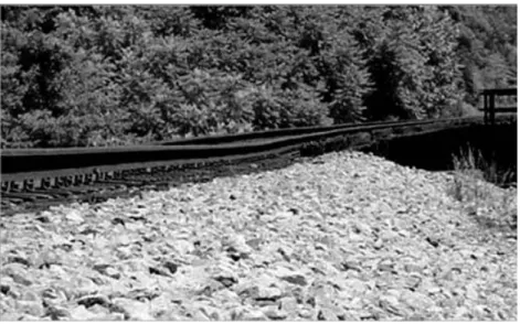
An abrupt change in the vertical stiffness of the track causes the wheel to experience an equally abrupt change in elevation because of the uneven track deflection. The change in elevation causes vertical acceleration of the vehicle mass that generates an increase in the applied loading. This mechanism can be selfperpetuating as the dynamic loads increase the differential deflections and settlement leading to even higher forces (Kerr and Moroney 1993; Frohling et al. 1995; Hunt and Winkler 1997). The effect of the load increase depends on the direction of the train. When the train is moving from a higher to a lower stiffness condition—such as exiting a bridge deck, grade crossing, or tunnel invert—the dynamic load is applied to the lower-stiffness track, increasing the rate of settlement. This condition is characterised by deterioration of the track geometry, ballast migration, and tie movement on the lower-stiffness track, as shown in Figure 1. When the train is moving from a lower- to higher-stiffness track, the load increase occurs on the high-stiffness side of the transition over a short distance and is more of an impact loading. In this situation, typical problems are rail surface fatigue, tie deterioration, and rail seat pad deterioration as Figure 2 shows. In addition to the track stiffness change, the damage potential at track transitions is related to vehicle axle loads, speeds, and suspension characteristics.
Even if the dynamic effects are minimal, at grade ballasted track may inherently settle more than ballasted track on a structure or directfixation track, creating a dip in the surface at the transition. This is especially true when the structure abutment is built on a deep pile foundation where settlement is negligible.
Settlement of at-grade track can be highly variable because of geotechnical issues affecting the subgrade performance such as lowstrength soils, deficient soil placement and compaction, poor drainage, and erosion (Briaud et al. 1997; Smekal 1997; Hoppe 2001). Environmental factors such as wet/dry and freeze/ thaw cycles also affect subgrade settlement behavior.
Sasaoka and Davis (2005) categorize track transition problems and solution approaches in terms of differential settlement, track stiffness, and damping changes that are intrinsic to the different structuresUsing analytical techniques, an optimum damping value of 300 lb/in./sec/tie/rail was suggested for railway track that is adequately resilient and capable of efficiently distributing dynamic loads, particularly the higher-frequency impact loads. Field tests, however, showed a value of 50 lb/in./sec/tie/rail to be typical of stiff structures such as ballast and open deck bridges. Increased track damping on these structures will attenuate the dynamic loading at transitions.
It is clear that the above issues are related and whether considered from the viewpoint of uneven track stiffness and deflections or differential settlement driven primarily by geotechnical conditions, the goal of any technique intended to improve the performance of transition track is to minimize dynamic loads by equalizing or smoothing the vertical support condition and the dissipation of dynamic energy across the transition.
Figure 1 Typical differential settlement of a freight railroad ballasted track bridge approach.
Figure 2 Cracked concrete ties at the abutment of a freight railroad ballast deck bridge caused by impact loads.
1.4
Track Stiffness and Modulus
This section briefly discusses the terms ―track stiffness‖ and ―track modulus‖. a. Track stiffness (k) is the ratio of the applied wheel load (P) to rail deflection (y):
𝑘 = 𝑃 𝑦
b. Hay (1982) and others define track modulus as the supporting force per unit length of rail per unit:
𝑢 = (𝑘)
4/3
(64𝐸𝐼)1/3
Where:
u the track modulus (lb/in./in.). E the rail modulus of elasticity. I the rail moment of inertia.
It is important to note the fundamental difference between track stiffness and track modulus: track stiffness includes all track components, including the rail, whereas the track modulus calculation excludes the flexural stiffness of the rail and only represents the rail support condition. Track modulus is considered to be an important indicator of track quality and strength and is a required term in many track design calculations. Although ballasted track modulus is not often measured directly, as is the case with track geometry, measured track modulus values that have been published for specific track configurations in the freight operating environment (Kerr and Moroney 1993; Hay 1982; Read et al. 1994) indicate that moduli of 2,500 lb/in./in. or higher are typical of stable track structures, and values less than 1,500 lb/in./in. would be indicative of track prone to significant rail deflection and rapid track geometry degradation. To equate these numbers to rail transit, reference is made to Chapter 4 of TCRP Report 57: Track
Design Handbook for Light Rail Transit, in which similar values are listed (Parsons
Brinckerhoff Quade & Douglas, Inc. 2000). TCRP Report 57 gives typical modulus values for goodquality, timber-tie ballasted track as 2,000 to 2,500 lb/in./in. and 5,000 to 8,000 lb/in./in. for concretetie track. Extremely high track modulus can also adversely affect track performance. According to Redden et al. (2002), track modulus values higher than 10,000 lb/in./in. are undesirable because of the propensity for increased dynamic loads. Because the track is a resilient load distribution system, a decrease in resilience caused by a stiff support condition also decreases the transfer of wheel loads to adjacent ties, thereby increasing rail seat forces and ballast pressures. Lack of resilience also tends to amplify impact rail forces that are generated by wheel and rail surface anomalies and the high-frequency rail vibrations associated with them. These highfrequency vibrations are often associated with corrugation development (Ahlbeck 1990; Hay 1982) and can generate undesirable noise and vibration conditions. As stated, track modulus represents the overall stiffness of the rail support system including rail fasteners and pads, ties, ballast, and subgrade.
A parametric study performed by Selig and Li (1994), using the GEOTRACK model, indicated that stiffness of the subgrade was the most influential parameter of ballasted track modulus. Secondary influence parameters included the granular layer (ballast and subballast) thickness, rail fastener pad stiffness, and tie type (wood or concrete). Tie spacing and tie dimensions had minimal influence on the modulus. These findings implied that (1) maintenance activities not directly related to improvement of the subgrade, such as surfacing and tie renewals, will not significantly affect the track modulus and (2) environmental conditions that may affect subgrade properties and strength, such as wet/dry and freeze/thaw cycles, can substantially change track modulus on a seasonal basis.
The modulus of direct-fixation track is almost entirely a function of the stiffness and resilience of the elastomeric elements in the rail fastening system.
The modulus of direct-fixation track is, therefore, much more consistent and easier to estimate than that of at-grade ballasted track.
1.5
Transition Problems Test Results
The following section presents the results of tests sponsored by the Association of American Railroads and the Federal Railroad Administration on freight railroad transition problems.
1.5.1
Track Geometry Degradation (Differential Settlement)
Figure 3 shows a comparison of the results of tests on average track settlement on four ballast deck railroad bridges and their approaches (Li and Davis 2005).
Figure 3 Comparison of track settlement accumulated over a maintenance interval (elevation change of unloaded rails).
As illustrated, the approaches experienced more track geometry degradation than the tracks on the bridges and the open tracks.
The settlement of the track on the bridges was approximately one-third of the settlement from the bridge approaches. Figure 4 further illustrates the differential nature of track settlement in the approach areas (settlement results versus distance from the bridge abutment).
Figure 4 Settlement in approach areas (track settlement on bridges not shown, negative and positive distance indicate two approaches for each bridge).
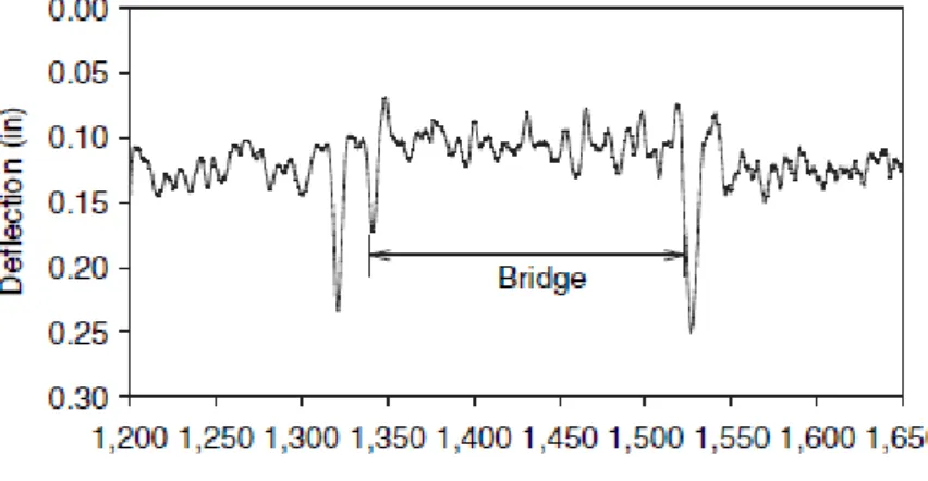
Figures 3 and 4 show accumulated track geometry degradation (differential track settlement). These results were measured from the unloaded rail surfaces using survey equipment. Figure 5 shows the deflection profile results obtained under the TLV (Track Loading Vehicle) moving test load (40-kip wheel load) for one of the four sites tested. The results were obtained after a surfacing maintenance operation, when the unloaded track profiles were ―smooth.‖ Nevertheless, as illustrated in Figure 5, the approaches still showed large and variable track deflections under load, indicating an apparent factor contributing to poor vehicle/track interactions. Note that deflection results shown in Figure 5 included not only the contribution from the ballast, subballast, and subgrade layers, but also the contribution of possible gaps and slacks between ties and ballast, which would close under the loaded condition.
1.5.2
Track Modulus
Figures 6 and 7 show track modulus test results obtained for two railroad ballast deck concrete bridges (with concrete ties) and their approaches (Li and Davis 2005).
As shown, the track structure on concrete bridges had high stiffness characteristics. On average, the measured track modulus on these bridges was approximately 10,000 lbs/in./in., which, as mentioned previously, is too high to accommodate desirable vehicle/track dynamic interaction. In addition, the change of track stiffness between bridge and approach was also too high (by a factor of 2, on average).
Figure 6 Track modulus test results (Site 1).
1.6
Discussion of Transition Remedies
In the literature, a number of remedies have been proposed or used to provide gradual stiffness transition. The following is a summary and discussion of those remedies.
1.6.1
Kerr and Moroney (1993) Transition Categories
Kerr and Moroney propose the following three categories of track transition remedies:
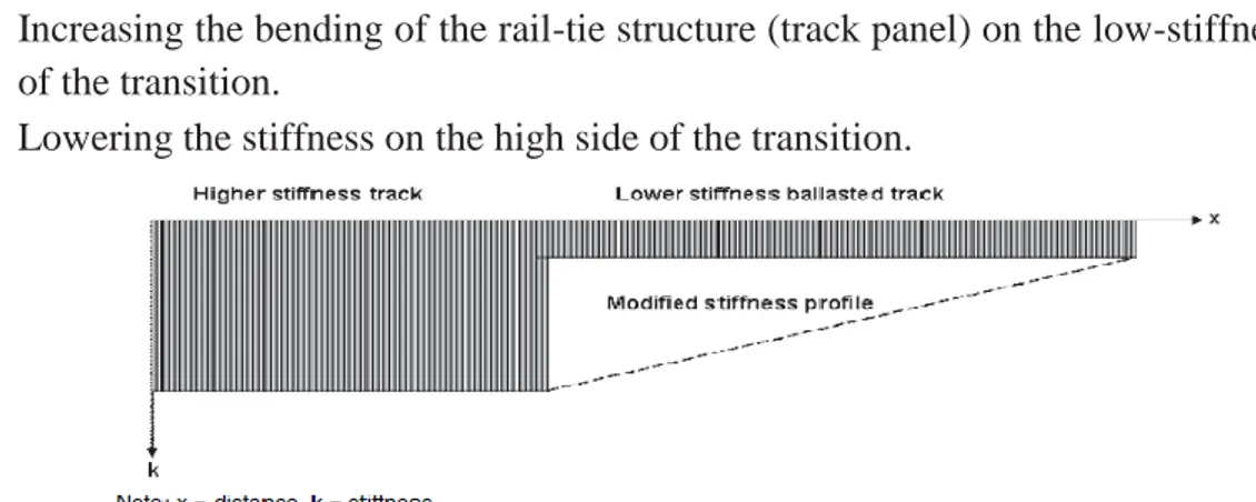
Smoothing the stiffness/modulus step change at the interface by gradually increasing stiffness on the lower-stiffness side of the transition, as shown in Fig 8.
Increasing the bending of the rail-tie structure (track panel) on the low-stiffness side of the transition.
Lowering the stiffness on the high side of the transition.
Figure 8 Transition remedy in which the stiffness step change is modified with a gradual increase in stiffness.
1.6.2
Increasing Track Stiffness with Long Ties
One of the oldest, simplest, and most widely used transition designs is installation of a series of increasingly longer ties on the ballasted track side of the transition. A typical layout is found in Plan No. 913-52 of the American Railway Engineering and Maintenance of Way Association (AREMA) Portfolio of Trackwork Plans (AREMA 2005a) and is shown in Figure 9.
1.6.3
MARTA Variable Length Timber-Tie Transition
A case study was published by Patel and Jordan (1996), involving the Metropolitan Atlanta Rapid Transit Authority (MARTA), in which four 10-ft timber ties followed by four 11-ft and four 12-ft timber ties were installed at 24-in. centers as a transition between ballasted at-grade, concrete-tie track and direct-fixation structures. The transition also included a 20-ft-long concrete transitional slab on the ballasted track approach. After modeling a number of options with GEOTRACK, the design shown in Figure 10 was chosen for the test. Patel and Jordan (1996) indicate that the variable length design reduced maintenance costs by a factor of 3 when compared to designs that included the approach slab but not long ties. The variable length design has been adopted for future new construction.
1.6.4
HMA Underlayment
The positive performance of an HMA pavement layer placed between the subgrade and ballast to reinforce weak subgrades is well documented in Rose 1998, Rose et al. 2002, and Li et al. 2001. These studies indicate that when properly designed and installed an HMA layer will reduce subgrade stresses and differential settlement and extend track maintenance cycles. Because it is a structural layer, HMA can reduce subgrade stresses to levels that will not exceed the compressive strength of low-strength soils.
However, in tests on the Union Pacific Railroad, Li and Davis (2005) found that HMA, placed on the approach to a ballast deck concrete bridge with a well-compacted subgrade, did not reduce the geometry deterioration of the approach compared with a similar approach without HMA. In the Li and Davis 2005 study, the track modulus of the approach with HMA was about 6,000 lb/in./in., which was very similar to the modulus of the non-HMA approach. The modulus on the ballast deck bridge in both cases was between 9,000 and 12,000 lb/in./in. The test data indicated that the HMA layer provided little improvement to a subgrade with high load-bearing capacity, and the differential settlement seen on the approaches was caused primarily by settlement in the ballast layer rather than the subgrade.
These results suggest that HMA and other methods used to improve performance of weak subgrades, such as geocell and soil cement, will not improve ballast performance on stiff subgrades. For cases in which the approach track stiffness is already high, it would appear that trying to further increase the approach stiffness is not as effective as reducing the stiffness of the bridge track.
1.6.5
Increasing Approach Stiffness at Grade Crossing
A transition to improve ride quality and maintenance demand at the approach to a grade crossing is described by Zarembski and Palese (2003). In this case, a transition grade crossing design was developed, installed, and tested on New Jersey Transit‘s Atlantic City line. The design was developed with the aid of an analytical model and provides a transition from low-modulus ―parent‖ track to a high modulus, concrete-panel grade crossing in the following steps:
1. Standard track with spikes and wood ties, 2. Wood ties with Pandrol clips,
3. 10-ft ties with Pandrol clips and single 8-ft field-side crossing panel installed between the rails,
4. 10-ft ties with Pandrol clips and 8-ft gage-side crossing panel installed between the rails,
5. Full 24-ft crossing.
Measurements of track modulus and vehicle acceleration taken before and after installation of the transition grade crossing indicated that the transition was effective at smoothing the track stiffness difference and that a 77% reduction in the dynamic overloading in the crossing had been achieved.
1.6.6
Additional Rails
The German Federal Railways have developed a design for the InterCity Express (ICE) high-speed lines on which lengths of rails are installed between the running rails and on the field side of the running rails to stiffen the ballasted track panel (Kerr and Moroney 1993). This condition often exists by default, when guard rails installed on open deck bridges extend beyond the abutment to the ballasted track.
1.6.7
Concrete Bridge Approach Slabs
A reinforced concrete slab that rests on the abutment or slab structure and is tapered toward the atgrade end is often used at transitions to direct-fixation aerial structures and tunnel/subway inverts.
Figure 11 Transition design from TCRP Report 57: Track Design Handbook for Light Rail
AREMA recommends using a slab that is a minimum of 20 ft long and that is tapered from 18 in. at the structure end to 12 in. at the at-grade end. TCRP Report 57 (Parsons Brinckerhoff Quade & Douglas 2000) shows a slab that is 12 in. thick and 20 ft long over which the ballast depth tapers from 12 in. at the structure end to 14 in. at the at-grade end (see Figure 11).
General specifications for an approach slab design, based on a successful trial in the United Kingdom, are provided by Sharpe et al. (2002). In addition to the slab, this design calls for vertical adjustment of the rail on the direct-fixation bridge deck. The adjustable fasteners permit the rail on the ballasted side to be raised higher than the desired final elevation and to settle to the desired final elevation (design tamping). The paper indicates that incorporating the design-tamping capability has improved the transition performance over that of an approach slab by itself. The use of approach slabs is also a common highway transition practice (Briaud et. al. 1997). The most successful highway slabs have slope changes of 1/200 or less, which is more gradual than railway designs, which are typically 2-in. changes over 20 ft or 1/120.
1.6.8
Slab Track Approach
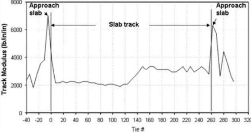
Concrete approach slabs 25 ft in length were installed at the Transportation Technology Center (TTC) in Pueblo, Colorado, to provide the transition from at-grade, concrete-tie track to a 500-ft-long concrete slab track test section (Bilow and Li 2005). The cast-in-place, 12-in.-thick reinforced concrete approach slab, prior to construction of the slab track, is shown in Figure 12. This transition design uses concrete ties with about 16 in. of ballast between the ties and the approach slab. The slab also has vertical walls to confine the ballast shoulder below the subgrade level.
Figure 12 Slab track transition at TTC.
Track modulus data taken on the completed track (see Figure 13) showed the modulus at the approach slabs to be more than two times the modulus of the slab itself.
In this case, the stiffness of the slab track direct fastening system had been successfully designed to approximate the nominal modulus of the surrounding wood-tie track (approximately 2,500 lb/in./in.). But the approach slab transition was over designed, creating an unnecessarily high (6,000 to 7,000 lb/in./in.) track modulus at the interface.
Figure 13 TTC slab track modulus data showing increase in modulus of the approach slabs.
1.6.9
Stone Columns
Stone columns (geo-piers) were installed at the Union Pacific Cedar River bridge approach for longterm performance monitoring (Davis et al. 2003). A stone column is simply a hole, 30 in. in diameter and 7 ft deep, that is bored into the subgrade beneath the rail seat and backfilled with aggregate material that is compacted in 6-in. layers. In this case, 10 pairs of columns spaced longitudinally at 5-ft centers were installed (see Figures 14 and 15). Stone columns are designed to strengthen and enhance drainage of weak subgrades. The test results have been positive, with no record of maintenance at the site during the first year of service.
Figure 15 Stone columns installed in approach subgrade.
1.6.10
Piles and Micro Piles
In addition to stone columns, Li et al. (2003) indicate that other types of piles, including concrete, timber, and sand columns are accepted methods of stabilizing weak subgrades. Unless the end of the pile is on a firm foundation, skin friction provides most of the load transfer capacity. Therefore, the pile‘s effectiveness will depend on its length, and different lengths can be used to smooth the stiffness of the approach.
Micropiles, also known as minipiles, (and less commonly as pin piles, needle piles and root piles) are deep foundation elements constructed using high-strength, small-diameter steel casing and/or threaded bar. Capacities vary depending on the micropile size and subsurface profile. Allowable micropile capacities in excess of 1,000 tons have been achieved. The micropile casing generally has a diameter in the range of 3 to 10 inches. Typically, the casing is advanced to the design depth using a drilling technique. Reinforcing steel in the form of an all-thread bar is typically inserted into the micropile casing. High-strength cement grout is then pumped into the casing. The casing may extend to the full depth or terminate above the bond zone with the reinforcing bar extending to the full depth. The finished micropile (minipile) resists compressive, uplift/tension and lateral loads and is typically load tested in accordance with ASTM D 1143 (compressive), ASTM D 3689 (uplift/tension), and ASTM D 3966 (lateral). The technique has been used to support most types of structures. Many geotechnical construction companies have the capability of combining their micropile technology with one or more of their other ground modification techniques to meet unique or complex project requirements cost-effectively and efficiently. Lines of micropiles spanned by wooden lagging can be ideal where excavation walls are required in low headroom and other confined areas.
Post-grouting within the bond length can increase frictional forces with surrounding soils, thus achieving greater capacity.
Micropiles can serve to ―stitch‖ the soil together, within predicted shear zones to enhance mass stability. In liquefiable profiles micropiles can transfer loads to competent bearing strata to conform to seismic design requirements. Underpinning of foundations adjacent to planned excavations is another micropile application.
For planned foundations in areas with multiple underground utilities, the cost of a cast-in-place piling system may often be substantially increased by the expense of utility re-routing, creation of adequate access, and sometimes even a shutdown of facility operations. These complications are often an issue: small diameter micropiles can be installed while avoiding existing utilities. Moreover, micropiles greatly alleviate the quality assurance concerns associated with cast-in-place piling in weak soils.
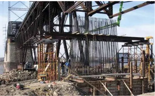
Figure 17 Micropiles for foundation rehabilitation of the Merchants Railway Bridge in St Louis, MO
1.6.11
Geogrid Reinforcement
The use of geogrids in road and railway projects is becoming an important practice all around the world for solving many design and construction problems. Applications include: reinforced soil walls and steep slopes, asphalt reinforcement, stabilisation of road and railway bases on soft ground, basal reinforcement of embankments on soft soil, spreading of load over piles. Below we presents the various applications, focusing on the technical details and providing sketches about the available design methods. Then the characteristics required for the geogrids are introduced, together with the related testing methods. Specific geogrids presently available on the international market are introduced and practical recommendations are provided.
1.6.11.1 BASIC PRINCIPLES OF REINFORCED SOIL
A simple model helps to explain the principle on which the reinforced soil techniques are based. Let us consider the soil element in Figure 16, which is part of an infinite mass of soil: the application of a vertical stress σv causes a deformation in the elemet and the consequent horizontal stress σh caused by the lateral compression suffered by the adjacent soil. Horizzontally the soil element undergoes a ―tensile deformation‖ εv , which is one of the principal causes of local failure. When, as in Figure 16b, a reinforcing element is put in the soil, the application of a vertical stress is followed by the deformation of the soil element and the extention of the reinforcement. This extension then generates a tensile strength T in the reinforcement, which in turn produce a horizontal stress σh . This stress, which also provides a confinement action on the soil granules, greatly contributes to resist the horizontal forces and to reduce the horizontal deformations. Therefore the inclusion of a geogrid into the soil mass reduces the stresses and strains applied to the soil: on the other hand the vertical stress σv applied to the soil mass can be increased, compared to the unreinforced soil, at equal deformations. With regards to the resistance to the shear stresses, according to Figure 17 in a non-cohesive soil element we have:
𝜏𝑦𝑥 𝑚𝑎𝑥 = 𝜎𝑦× 𝑡𝑎𝑛 𝜙𝑚𝑎𝑥
Where:
– 𝜙𝑚𝑎𝑥= maximum angle of shear resistance of soil; – 𝜏𝑦𝑥
𝑚𝑎𝑥 = maximum overall shear stress provided by the soil
When the soil element is crossed by a reinforcing element which makes a θ angle with the shearing direction (Figure 18), the state of stress is modified because the tension T generates a shear stress produced by tangential component T × cos θ generates another τyz caused by the friction angle ϕmax in the soil.
Therefore: (𝜏𝑦𝑥𝑟)𝑚𝑎𝑥 = 𝜎𝑦𝑟 × 𝑡𝑎𝑛 𝜙𝑚𝑎𝑥 + ( 𝑇 𝐴𝑠 ) × 𝑐𝑜𝑠 𝜃 × 𝑡𝑎𝑛 𝜙𝑚𝑎𝑥 + ( 𝑇 𝐴𝑠 ) × 𝑠𝑖𝑛 𝜃 Where:
– 𝐴𝑠= area of the soil element;
– 𝜏𝑦𝑥𝑟
So the normal stress on the soil elemet is increased by:
𝜎𝑦 = (
𝑇
𝐴𝑠
) × 𝑐𝑜𝑠 𝜃
While the maximum shear stress which the soil can carry is increased.
The main advantages of a reinforced soil structure are the following:
– Lower global cost: the possibility to build with steeper slopes reduces the quantity of the material needed for an embankment;
– Moreover, it is possible to use less valuable and then cheaper materials;
– Improved stability: the reinforcement guarantees an improvement in the Factors of Safety;
– It is possible to build directly on low bearing capacity soils;
– A reinforcement on the base allows to build on soft soils, that would normally request a preliminary consolidation and great caution during construction.
Figure 19 Stresses and strains due to vertical load
in an unreinforced (a) and a reinforced (b) soil element
Figure 20 Shear stresses in an unreinforced soil element
1.6.11.2 POLYMERIC REINFORCEMENT
Polymeric reinforcement takes many forms, such as strips, grids or sheets which may or may not be connected to a facing. Like steel strips, polymeric strips are installed at predetermined vertical and horizontal spacings. In contrast, grids or sheets are usually installed as full width reinforcement in which case only a vertical spacing is specified. The most commonly used polymers are polyester and polyolefins although aramid and carbon fibre reinforcements are available. All polymeric materials used in the manufacture of fill reinforcement are subject to molecular orientation during production to minimise the effects of creep.
POLYESTER (PET)
Polyesther is a polymer commonly utilized in the form of fibres. The most common form (Fig. 22) of Polyester is Polyethylene Terephtalate (PET), which is obtained by condensation of a dibasic acid and a dialcohol. It is composed of groups of ethylene and groups of terephtalate. The plain aromatic group stiffen the structure of the mulecular chain. The esteric groups of Polyester are either positive or negative, therefore they attract each other, allowing the adjacent polymer chains to line up in christalline form. This allow the production of thin fibers of high tenacity.
Figure 22 The molecular structure of Polyethylene Terephtalate (PET)
– The PET fibers can be composed into high strength yarns, which can be woven or knitted to produce high strength geotextiles and geogrids.
– Geotextiles and geogrids produced with high tensile modulus Polyester yarns present high tensile strength with excellent low creep properties. PET is generally sensitive to chemical degradation due to hydrolosis in very acid (pH<2) or very alcaline (pH > 12) environvent. The resistance against chemical degradation is influenced by the molecular weight Mw and by the carboxyl end group (CEG) of the polymer used to make the fibres. The higher the Mw and the lower the CEG, the better the yarn performance.
ARTER® AND MACRIT®
Many companies produce geogrids and geotextiles based on high tenacity PET yarns. Geosynthetics range presently can include the following products:
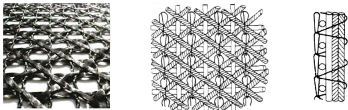
– ARTER®: is a D.O.S. (Directionally Oriented Structure) textile geogrid manufactured by means of warp knitting technology with weft insertion (Fig. 23C). In the D.O.S. structure the elongation is only due to the yarns used, while there is no practical elongation of the geogrid structure, since the yarns are straight and parallel. ARTER geogrids are differentiated between ARTER® GTS (Fig. 23A), which is coated with EVA polymer, and ARTER® GT (Fig. 23B), which is uncoated.
A) B) C)
Figure 23: ARTER® geogrids: A) ARTER® GTS; B) ARTER® GT; C) The D.O.S. structure
– MACRIT®: is a geocomposite consisting of a nonwoven geotextile coupled to a monoaxial or biaxial D.O.S. geogrid reinforcement (Figure 24); the geogrid has the same characteristics of ARTER® GTS, while the nonwoven geotextile provides drainage, separation, and filtration features.
A) B) C)
Figure 24 MACRIT® geocomposites: two of the available products (A and B) and the structure
(C)
– ARTER® GTS, ARTER® GTS A, and MACRIT® GTS V: are both coated with EVA (Ethylene vynilacetat) polymer (Figure 25) and were specifically developed for asphalt reinforcement applications.
– MULTIAXIAL: is a D.O.S. multiaxial textile geogrid, manufactured by warp knitting technology (Figure 26); it is a unique product, the most technologically advanced geogrid presently on the market; thanks to the othogonal and diagonal ribs it yields multiaxial reinforcement capability and dimensional stability.
Figure 26 MULTIAXIAL is a geogrid with both orthogonal and diagonal ribs
The presence of high tenacity Polyester yarns ensure the best technical characteristics. The high creep resistance of a good geosynthetics was demonstrated by creep and creep rupture testing performed on the high tenacity yarns through the Stepped Isothermal Method (SIM). SIM creep test starts with a constant load applied to the yarns at a reference temperature. After a specified time exposure and without releasing the applied load, the temperature is increased rapidly. This procedure is repeated for several temperature steps. The number, height and duration of the temperature steps are designed to produce a master curve of creep strain and creep modulus over a long period. Extrapolation of results up to 1,000,000 hours (115 years) is possible and it allows to determine the creep properties of the polyester yarns over the entire design life of a civil engineering structure. The master creep modulus curves of the yarns are shown in Figure 27 for a creep load equal to 60 % of the ultimate tensile load. It can be noted that, even at such high sustained load, the strain at 100 years never exceed 9 %. Moreover the CEG of the PET used for the yarns is always in the range of 15 - 25 meq/kg and the Mw is always higher than 50,000 g/mol, thus ensuring the highest chemical resistance. This confirms the high technical characteristics of geosynthetics and their suitability for all kind of reinforced soil structure.
1.6.11.3 GEOSYNTETHICS IN ROADWAYS AND RAILWAYS
BASES
Roadways and railways may fail due to structural deficiencies, which can occur expectedly at the end of the design life or prematurely. The development of permanent strain in the base and subgrade materials with continued traffic loading can eventually result in an excessive rut depth. In this case, geosynthetic reinforcement of the roadway system could be used to enhance structural characteristics. In another case, the mixing of the subgrade with the base course would lead to a deterioration of the mechanical properties of the base course layer. In this situation, use of a geosynthetic separator/filter would ensure the structural integrity of the base aggregate and the capacity of the roadway. Geosynthetics can be used to reduce the design cross-section of the roadway such that a roadway of equal life results. Alternatively, geosynthetics can be added to the original design cross section to extend the life of the roadway and to decrease maintenance costs. Geosynthetics can also be used to great advantage during the construction of a roadway over soft soils where separation and reinforcement can aid in the construction of a working platform for the remaining construction.
Geosynthetics (geogrids and geotextiles) in roadways play functions that fall into four categories: reinforcement, separation, filtration and drainage.
1. REINFORCEMENT:
The function of reinforcement pertains to the ability of the geosynthetic to aid in supporting vehicular traffic loads, where these loads may be due to construction traffic or daily operating traffic. Reinforcement plays the function of lateral base course restraint and the tensioned membrane function.
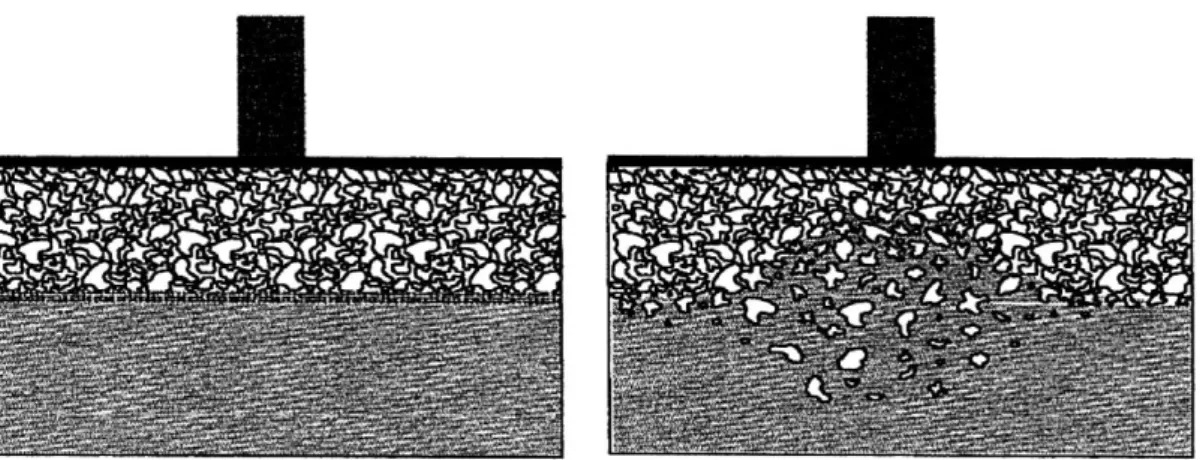
Lateral Base Course Restraint: the reinforcement function of lateral base course restraint develops through shear interaction of the base aggregate with the geosynthetic contained in or at the bottom of the base layer (Figure 28).
The development of shear interaction at the base-geosynthetic interface potentially results in four reinforcement mechanisms commonly lumped together under the heading of lateral base course restraint.
As illustrated in Figure 29, vehicular loads applied to the roadway surface create a lateral spreading motion of the base aggregate. Tensile lateral strains are created at the bottom of the base as aggregate moves down and out away from the applied load. Lateral movement of the base aggregate allows for vertical strains to develop leading to a permanent rut in the wheel path.
Placement of a geosynthetic layer or layers in the base aggregate allows for shear interaction to develop between the base and the geosynthetic as the base aggregate attempts to spread laterally. Tensile load is in effect transmitted from the base aggregate to the geosynthetic layer.
Since the geosynthetic is considerably stiffer in tension as compared to the base aggregate, far less lateral tensile strain develops in the system. This first reinforcement mechanism results from less lateral strain being developed in the base, which results in less vertical deformation of the roadway surface. The shear stress developed between the base aggregate and the geosynthetic provides an increase in lateral stress within the bottom portion of the base. This increase in lateral confinement leads to an increase in the mean hydrostatic normal stress in the aggregate.
Granular materials generally exhibit an increase in elastic modulus with increasing mean stress, meaning that the base aggregate becomes more stiff when adequate interaction develops between the aggregate and the geosynthetic.
This second reinforcement mechanism, an increase in modulus due to lateral confinement of the base, also results in less vertical strain being developed in the base aggregate.
While this mechanism controls the development of rut depth, it might also be expected that an increase in modulus of the base would result in lower dynamic, recoverable vertical deformations of the roadway surface, meaning that fatigue of an asphalt concrete layer in a flexible pavement would be reduced by this mechanism.
For layered systems, where a weaker, less stiff subgrade material lies beneath the base aggregate, an increase in modulus of the base also means that this layer will aid in distributing load on the subgrade. This third reinforcement mechanism reduces vertical stress in the base and in the subgrade beneath the centerline of the wheel.
A reduction of vertical stress results in lower vertical strain in these layers. As a result of an improved load distribution, the deflected shape of the roadway surface would have less curvature.
The presence of a geosynthetic layer in the base course layer can also lead to a change in the state of stress and strain in the subgrade material. As noted above, the increased stiffness of the base layer leads to a reduction of vertical stress in the subgrade. It is also expected that shear stress transmitted from the base aggregate to the subgrade would be reduced. Hence, this fourth reinforcement mechanism results from less shear stress being developed in the subgrade, which, when coupled with lower vertical stress, results in a less severe state of stress leading to lower vertical strain in the subgrade.