UNIVERSITÀ
DEGLI
STUDI
DEL
MOLISE
Department of Agricultural, Environmental and Food Sciences
PhD Course in:
AGRICULTURE
TECHNOLOGY
AND
BIOTECHNOLOGY
(CURRICULUM:SUSTAINABLEPLANTPRODUCTIONANDPROTECTION)
(C
YCLEXXX)
Related disciplinary scientific section: AGR/09 (Meccanica Agraria)
PhD thesis
CONTROLLED MECHANICAL VENTILATION
TO REDUCE PRIMARY ENERGY
CONSUMPTION IN AIR CONDITIONING OF
GREENHOUSES
Coordinator of the PhD Course: Prof. Giuseppe Maiorano
Supervisor: Prof. Antonio De Cristofaro
Co- Supervisor: Prof. Ing. Pasquale Catalano
PhD Student: Claudio Perone
153741
NOMENCLAURE
A area [m2]
BLDC brushless direct current
CE confined environment
COP coefficient of performance [Wth/We]
E primary energy [Wh]
EAHP exhaust air heat pump
EE external environment
HPT high pressure transducer
i index
LPT low pressure transducer
n speed of compressor [rps] / number of air change per hour [1/h]
P heat/power
q heat gains / losses [W]
T temperature [°C]
U Thermal transmittance [W/m2K]
V volumetric flow rate [m3/h]
V volume [m3] Greek symbols Δ difference ε efficiency η temperature ratio ρ density Subscripts a air AI air in AO air out c condensation DB dead band DIS discharge
DIS_ST static discharge
e electric / evaporation
E exhaust
EAHP exhaust air heat pump
f floor
h heating system
HP heat pump
inf infiltration
m motor
net net value
O outdoor R recovery / refrigerant R_ST static recovery ref refrigerant ren renewal S supply
s system / specific / sensible
S_ST static supply
SET set-point
SET_calc calculated set-point
sh_d delivery superheat
sh_s suction superheat
SIVeMeC SIVeMeC prototype
SO solar
sub_s summer subcooling
sub_w winter subcooling
T total
Umax maximum useful
vi ventilation in
vo ventilation out
w wall
Superscripts
1 without electrical absorption of fans
ABSTRACT
In order to ensure optimal growing conditions inside greenhouse it becomes necessary a very close control of the internal climate conditions. In the first section, the available conditioning plant solutions are described. However, these systems generally require high investment costs. In addition, also high operational costs are required for an efficient solution without reducing yield crop or quality. Therefore, the winter conditioning of the internal air of a greenhouse occurs by means of fossil fuels. The use of a mechanical ventilation system contributes to a proper control of temperature, relative humidity and CO2 rate. However, the literature about the application of mechanical ventilation with heat recovery applied in greenhouses conditioning is very poor. For this purpose a research is being carried out.
In section 2 a prototype of a mechanical ventilation unit and two climate rooms, for the reproduction of external and internal (built in laboratory) conditions, are described. The recovery unit is equipped with a heat pump and is able to increase the thermal energy recovered by the flow of exhaust air and through a high efficiency heat exchanger.
A first study was carried on to evaluate the energy performances of the system during the control of temperature in winter season. Tests reported in section 3 were performed at different temperature values of simulated outdoor air TO (-5 °C, 0 °C, 5 °C and 10 °C) and a fixed (reference) internal simulated greenhouse temperature (20 °C). Each trial was performed with a ventilation flow rate of 535 m3/h. The resulting Coefficient Of Performance of the overall system (COPs) is 9.50 at 0 °C, 8.86 at 5 °C and 6.62 at 10 °C respectively. It has to be highlighted that during the trials carried out at -5°C the compressor behaved as an on-off type. This is due to a safety mechanism for the defrost of the evaporator. In addition, the ventilation flow rate was reduced to avoid a too low value of the supply air temperature. For the other trials (TO = 0 °C or 5 °C), the overall COPs decreases when the external temperature increases, due to a lower difference between external and indoor air enthalpy. To study a real case the mechanical ventilation unit was also installed at service of a greenhouse at Vivaio Verde Molise, Termoli – Italy. The experimental apparatus, described in detail in section 4, consists of the mechanical ventilation system, a perforated duct for air distribution, a fog system to adjust humidity and a supervision system to acquire the field data. Another dedicated supervision system allows measuring and collecting all the parameters of the prototype, such as thermophysical parameters of the airflow, thermophysical parameters of the refrigerant circuit of the heat pump, status and alarms of the unit.
First tests, carried out on temperature control in winter season, are analysed in section 5. They show that the indoor air temperature (set at 27 °C) is suitable regulated by driving the unit with the reference probe installed on the recovery side. Only an offset of few Celsius degree is observed due to duct heat loss and the recovery grid placed on one side. Moreover, the mechanical ventilation system had also shown notable energy performance: COPs (mean value) of 5.4 and 5.7 at outdoor air temperature of 18.0 °C and 15.7 °C respectively.
ACKNOWLEDGMENTS
Firstly, my great gratitude goes to my two supervisors, Prof. Antonio De Cristofaro and Prof. Pasquale Catalano, for their guidance and for their valuable suggestions that made the development of this work possible.
I must thank too the agricultural engineering working group, in particular Prof. Ferruccio Giametta for assisting me during my period abroad at Kyoto University.
Special thanks are also due to Prof. Flavio Fucci for welcoming me in the agricultural engineering working group and for his always-precious teachings.
I would also like to extend my appreciation to Clifel S.r.l. for having funded a substantial part of the research within the POR FESR Program Molise 2007–2013 Activity I.2.1.
Finally I want to thank my family who has always supported me. They always provided to me the assistance and the strength throughout my studies.
A loving thank is for my daughter Danila, my darling, to whom this work is dedicate. She gave me one more reason to face the challenges encountered on my path.
LIST OF FIGURES
Figure 1: classification of air-conditioning systems [2]... 3
Figure 2: air-condensing unit. ... 18
Figure 3: air-evaporator unit. ... 18
Figure 4: immersed electrodes humidifier. ... 19
Figure 5: connection duct from external environment to the suction side of the system. ... 20
Figure 6: fan-coil reproducing summer temperature values. ... 20
Figure 7: heat pump external units. ... 21
Figure 8: confined environment split unit. ... 21
Figure 9: radiator with thermostatic valve. ... 22
Figure 10: immersed electrodes humidifier in the confined environment. ... 22
Figure 11: climatic rooms a) E.E. climatic room with the plenum room, b) C.E. climatic room. ... 23
Figure 12: general control panel. ... 23
Figure 13: electric power panel and refrigeration plant panels. ... 24
Figure 14: SIVeMeC installation and its connections with climatic rooms. ... 25
Figure 15: “wire sheet” programming for the control logic design. ... 27
Figure 16: user-interface for the managing of the climatic rooms conditions. ... 28
Figure 17: SIVeMeC user-interface for control and managing. ... 29
Figure 18: SIVeMeC heat-pump user-interface. ... 29
Figure 19: schematic laboratory user-interface page. ... 30
Figure 20: history page to select the variables of interest for historicization. ... 31
Figure 21: SIVeMeC prototype... 32
Figure 22: psychrometric transformation of renewal air (blue line) and exhaust air (red line) on Mollier diagram... 34
Figure 23: pressure drop (PD) through the heat exchanger in function of volumetric airflow rate AV; the line PD/AV is that for 500 m3/h. ... 35
Figure 24: heat pump cycle in winter arrangement. 1) BLDC compressor; 2) evaporator; 3) condenser; 4) electronic expansion valve; 5) inverter for compressor driving; 6) 4-way valve; 7) liquid receiver; 8) dehydrator filter; 9) sight glass; Tsh_s suction superheat temperature; HTP high pressure transducer; LPT low pressure transducer; Te evaporation temperature; Tc condensation temperature; Tsh_d delivery superheat temperature; Tsub_w subcooling temperature in winter arrangement; Tsub_s subcooling temperature in summer arrangement; µPC control panel. ... 36
Figure 25: compressor performance curves at 60 rps (right) and 30 rps (left). ... 38
Figure 27: E2V smart electronic expansion valve. ... 40
Figure 28: six rows expansion coil. ... 41
Figure 29: two rows expansion coil. ... 42
Figure 30: technical drawing of electronic fan ... 43
Figure 31: fan characteristic curves. ... 44
Figure 32: by-pass duct above the heat exchanger. ... 45
Figure 33: remote panel PGD1. ... 47
Figure 34: integrated simulator 1Tool® ... 48
Figure 35: 1Tool® screen. The sidebar contains the pages that make up the strategy. The "AnalogInput" page is open in the main window. ... 50
Figure 36: two PID controllers in series to manage compressor, delivery air fan and exhaust air fan. ... 51
Figure 37: 1Tool® part of program for compressor calling. ... 52
Figure 38: 1Tool® program part for fans speed regulation by using CO2 probe as reference. ... 52
Figure 39: on-off behaviour of the compressor (test with TO = -5°C). ... 62
Figure 40: airflow rate reduction due to the high difference between TS e TSET_calc (test with TO = -5°C). ... 62
Figure 41: temperature trend at the evaporator inlet (test with TO = -5°C). ... 62
Figure 42: terms appearing in sensible energy balance of a typical agricultural building [1]. ... 66
Figure 43: mass balance for a typical agriculture building [1]. ... 68
Figure 44: dimensions of the greenhouse served by SIVeMeC. ... 71
Figure 45: experimental apparatus installed at Vivaio Verde Molise, Termoli - Italy. ... 73
Figure 46: perforated duct for supply air distribution. ... 74
Figure 47: solenoid valve. ... 75
Figure 48: experimental apparatus layout and probes location. ... 75
Figure 49: PlantWatch PRO®. ... 76
Figure 50: control panel equipped with energy meter. ... 78
Figure 51: user interface of pCOManager® for SIVeMeC monitoring. ... 79
Figure 52: Test 1 – exhaust air temperature (TE), supply air temperature (TS) and coefficient of performance (COPs) as a function of outdoor air temperature (TO). ... 82
Figure 53: Test 1 – coefficient of performance (COPs) as a function of the compressor speed. ... 83
Figure 54: Test 1 – temperature distribution inside greenhouse. ... 84
Figure 55: Test 2 – exhaust air temperature (TE), supply air temperature (TS) and coefficient of performance (COPs) as a function of outdoor air temperature (TO). ... 85
Figure 56: Test 2 – coefficient of performance (COPs) as a function of the compressor speed. ... 86
Figure 57: Test 2 – heat supplied by SIVeMeC (PR) as a function of compressor speed. ... 86
Figure 58: Test 2 – compressor speed as a function of exhaust air temperature TE. ... 87
LIST OF TABLES
Table 1: probe used in the laboratory ... 25
Table 2: typology and number of probes for each zone. ... 25
Table 3: REK +39 technical data according to EN 308: 1997. ... 33
Table 4: passive heat recovery PR_ST, residual heat load PHP_set, supply air temperature (TS_ST) and discharge air temperature (TDIS_ST) downstream the static recuperator, as a function of outdoor temperature TO for fixed values of exhaust air temperature (TE), temperature ratio η and both exhaust (VE) and supply (VS) airflow rate. ... 37
Table 5: technical data of DA75F0F – 11UA compressor. ... 38
Table 6: technical data of direct expansion coils. ... 42
Table 7: average values and standard deviation of the main physical measured parameters. ... 59
Table 8: average values and standard deviation of the main energetic calculated parameters. ... 60
Table 9: Comparison of the COP of different systems. ... 64
Table 10: values of thermal transmittance for values of wind speed below 4 m/s. ... 69
Table 11: Optimum temperature for different crops [35]. ... 71
Table 12: Heat losses by considering only transmission through structure and air infiltration. ... 72
INDEX NOMENCLAURE ... i ABSTRACT ... iii ACKNOWLEDGMENTS ... v LIST OF FIGURES ... vi LIST OF TABLES ... ix 1. INTRODUCTION ... 1 1.1 Research project ... 1
1.2 State of the art... 2
2 PROTOTYPE OF THE MECHANICAL VENTILATION SYSTEM – SIVeMeC ... 12
2.1 General aspects ... 12
2.2 Laboratory ... 16
2.2.1 Climatic rooms ... 16
2.2.2 Supervisory system ... 23
2.3 System configuration ... 31
2.3.1 Countercurrent heat exchanger ... 33
2.3.2 Heat pump ... 35
2.3.3 Electronic fans... 43
2.3.4 By-pass ducts ... 44
2.3.5 SIVeMeC ... 45
2.4 SIVeMeC control system ... 46
2.4.1 Temperature control ... 51
2.4.2 Heat pump control ... 51
2.4.3 Ventilation control ... 52
3 LABORATORY EXPERIMENTAL TESTS... 54
3.1 Experimental procedures ... 54
3.3 Results and discussion ... 58
4 GREENHOUSE EXPERIMENTAL APPARATUS ... 66
4.1 Greenhouse energy and mass balance ... 66
4.2 Experimental apparatus installation ... 72
4.2.1 Air and water distribution systems... 74
4.2.2 Field probes ... 75
4.2.3 Field supervisory system ... 76
4.2.4 SIVeMeC supervisory system ... 78
5 GREENHOUSE EXPERIMENTAL TESTS ... 81
5.1 Experimental procedures ... 81
5.2 Results and discussion ... 81
6 CONCLUSIONS ... 89
REFERENCES ... 91
STANDARDS ... 94 ATTACHMENT 1...
1
1. INTRODUCTION
This PhD thesis deals with the mechanical ventilation technology used to reduce the primary energy consumption in air conditioning within confined environment. This technology is well established in the civil sector but cannot be transferred to the agricultural one without an appropriate optimization. In fact, in this particular application the need to ventilate confined environments is important not only to guarantee the healthy air for the people welfare , but also for the animals welfare (in their shelters) and the growth of the protected crops in confined environments such as the greenhouses. Latter is the prevalent context in which this research can be developed, without excluding the other fields of application.
Greenhouses require an appropriate control of air temperature, relative humidity, carbon dioxide level and light. Suitable environmental condition have a direct effect on quantity, quality and timing of crops growth. The need for quantity is obvious (production increases when the temperature increases up to the point where damaging begins). Environmental conditions are critical in determining quality with many greenhouse crops. Also timing is very important for assuring profit (consider for example the market for poinsettias).
Heating, cooling, ventilation and air distribution are critical operations for environment control in greenhouses. While in cool climates it is possible to maintain suitable conditions by natural ventilation alone for plant growth during summer, mechanical ventilation is necessary for most conditions [1].
The increase of annual crop yield in a greenhouse is possible only through a very close control of the internal conditions. Currently available conditioning plant solutions require both high investment costs and high operational costs for an efficient solution without reducing yield crop or quality. Current conditioning systems applied in a greenhouse use fossil fuels, especially during winter. Ventilation systems could allow proper control of temperature, relative humidity and CO2 rate.
1.1 Research project
Aim of the present PhD thesis was to design and realize a high efficiency dynamic
mechanical-ventilation system (SIVeMeC – Sistema Integrato per la Ventilazione Meccanica Controllata:
Integrated System for Controlled Mechanical Ventilation) integrated with a heat pump. The system works adapting itself to the real ventilation need of the confined environment.
The performance of such system in different configurations was analyzed: a) static heat recovery;
2 b) thermodynamic heat recovery;
c) both thermodynamic and static heat recovery; d) free heating/free cooling.
Two climatic rooms were realized to evaluate the energy performance of the prototype and to reproduce different operative boundary conditions before applying it in a greenhouse.
Afterwards the tests carried out in laboratory the prototype was installed at service of a mini-tunnel greenhouse located at Vivaio Verde Molise, Termoli – Italy.
Plant growth and annual crop yield in greenhouse can be increased also through a very close control of the internal conditions. However, a close control of the climate condition of a greenhouse requires the installations of new technologies that may led to an additional energy consumption. Usually, greenhouse heating is done by firing fossil fuels in a boiler and this is disadvantageous at both the energy and environmental level.
The experimental apparatus consists of a mechanical ventilation system, a perforated duct for air distribution, a fog system to adjust humidity and a supervision system to acquire the field data. Another dedicated supervision system allows measuring and collecting all the parameters of the prototype, such as thermos-physical parameters of the airflows, thermos-physical parameters of the refrigerant circuit of the heat pump, status and alarms of the unit. In order to characterize the whole system under investigation it is possible to measure and collect temperature, relative humidity and carbon dioxide inside the greenhouse and temperature in all sections of the prototype. Other two mini-tunnel greenhouses used as references are monitored. One is heated with radiant tubes placed on the bench, and humidified with a fog system; the other is completely passively heated (without heating system) and humidified with the same fog system.
1.2 State of the art
Environmental control of greenhouses involves the managing of the main parameters that characterize the internal conditions. To this purpose, air conditioning systems are often used. Based upon their characteristics these systems are classified as heating systems, cooling systems and composite systems (Figure 1):
Heating systems: water storage, rock bed storage, PCM (Phase Change Materials) storage, movable insulation, ground air collector and north wall.
Cooling systems: natural and forced ventilation, shading and evaporative cooling (fan-pad, mist/fog and roof cooling).
3 Composite systems: EAHES (Earth-to-Air Heat Exchanger System) and ACCFHES
(Aquifer Coupled Cavity Flow Heat Exchanger System).
Figure 1: classification of air-conditioning systems [2].
The aim of the heating systems is to replace energy lost from the greenhouse when outside temperatures are lower than desired one in the greenhouse growing area. Apart from these factors overall performance of a greenhouse coupled with any heating system is influenced by several interrelated parameters such as: size of greenhouse, type of cover material used, heat storage method, quantity of material used, type of cultivation, desired day and night temperature of the inside air, location of the greenhouse and outside ambient conditions [2].
Water storage systems consist of: water filled plastic bags and ground tubes placed inside the greenhouse on the pathway between the row of plants, water tanks/barrels (sometimes black
4 painted) along the north side of the greenhouse that act as solar collectors and heat storage media. It was observed an increase of internal temperature of 2 – 6 °C by using plastic bags/tubes. The problem of using these systems is that about 20 – 25 % of the valuable ground surface becomes unavailable and cannot be used for cultivation [2]. Water tanks/barrels occupy lesser space inside the greenhouse as compared to ground tubes and allow an increase of internal temperature of 2 – 11 °C and can satisfy 25 – 62 % of the annual heating needs of the greenhouses at various locations.
Another popular and economical heat storage material is rock bed (pebble, gravel and bricks), in which the sensible heat is stored in an underground rock bed placed at a depth varying between 40 – 50 cm or outside the greenhouses. The air is used as the energy transport mechanism. The collected information shows that gravel having 20 – 100 mm diameter is preferred as bed material. Heat capacity of the gravel is 157.28 kJ/°C (about 220 kg) per m2 of greenhouse area and can satisfy 20 – 70 % of the annual heating needs [3]. Inside air temperature ranges from 4 to 13 °C above the minimum external air temperature. The main problems of this system are related to the huge quantity of rock pile required (due to the low thermal capacity) and the pumping cost of air through the rock pile (high pressure drop created by the resistance of the rocks).
Phase change materials (PCMs) are able to store a large amount of latent heat in the phase change from solid to liquid (latent heat of fusion) at the constant pressure and phase transition temperature. A circulating fluid (air or water) extracts the latent heat from the storage unit causing the solidification of the material then the cycle starts again. The most popular PCM used for greenhouse applications is calcium chloride hexa-hydrate (CaCl2 − 6H2O), which melts at 29 °C. The representative value of the latent heat capacity of this eutectic mixture used per m2 of the greenhouse ground area is approximately 2600 kJ, which is equivalent to 13.70 kg per m2[2]. The use of CaCl2 − 6H2O can increase the internal air temperature of 2 – 8 °C than the outside one and can satisfy 22 – 75 % of the annual heating needs. The energy storage density of CaCl2− 6H2O is over ten times higher than the rock bed but the current price is about four to five times than the gravel system to store the same amount of energy. Moreover, this inorganic compound is corrosive to most metals and suffer from decomposition and sub-cooling, which can affect its phase change properties.
Movable insulation is a passive system able to reduce the heat loss through the boundaries of the greenhouse. The main effect of the curtain is to provide additional thermal resistance that reduces the overall rate of heat transfer to the surroundings. During daytime, the movable
5 insulations are removed in order to allow solar radiation to enter and closed during nighttime to reduce thermal losses. Generally, their internal installation is to be preferred because it reduces the thermal conductivity of the structure. Furthermore, if aluminized polyester sheets are used on both side of the curtain, the maximum energy saving is obtained. A study was carried out to observe the effect of different greenhouse design parameters and heating systems on the greenhouse energy saving [4]. Curtains reduce the nighttime heating requirement by 70.8 % and daily requirement by 60.6 %. However, they have poor mechanical reliability, incomplete sealing after closure and are subject to condensation damage.
North wall consists of a thick thermal mass, made of brick or cement blocks filled with concrete able to capture and retain the solar radiation transmitted through the greenhouse. North wall is therefore externally insulated and internally painted black to increase thermal storage. The heat stored during daytime is released during the night (or when the internal temperature falls below the storage temperature). A study carried out on 30 small size greenhouses (20 m2 floor area each), using north wall heat storage made of 60 cm wide concrete blocks showed an indoor air temperature of 15 – 20 °C during winter conditions, when outside temperature was less than 10 °C [5]. Another study showed that these systems can cover about 35 – 50 % of greenhouse heating needs [6].
Ground Air Collector (GAC) is a flat plate collector installed in the ground subsurface. The information about the use of GAC is limited in literature. It comprises four components: (1) glazing for providing the greenhouse effect; (2) sand or concrete bed as an absorber of solar radiation; (3) tube or passage for conducting or directing the heat transfer fluid from inlet to outlet and (4) blower for air circulation [7]. The heat stored by the sand is transferred to the pipe embedded in it. The air circulating in the pipe is heated and then, the hot air is sent to the internal of the greenhouse, while the indoor air is drawn from the greenhouse and is heated again. It was seen that GAC can raise the inside air temperature by 5 – 6 °C during extreme winter condition [8]. However, 0.73 m2 GAC area is required per m2 of greenhouse area [2]. It also involves different cost items: pipes, air pumping, electric motor and blower assembly. The cooling systems include ventilation (natural and forced), shading and evaporative cooling (fan-pad, mist/fog and roof cooling). Ventilation consists of replacing the internal air with cool air from outside.
Natural or passive ventilation is based on differential pressure, between inside and outside, created by the wind and/or the greenhouse temperature. The external cool air enters through the
6 lower side openings while the internal hot air exits through the roof openings due to density difference between air masses.
In forced ventilation, systems like exhaust fans or blowers can supply high air exchange rates. Generally, ventilation can reduce the inside temperature, but the lower limit is represented by the external temperature. Moreover, in natural ventilation another critical factor is the rate of air exchange by free convection. A total vent area equivalent to 15 – 30 % of the floor area is recommended for effective cooling and the presence of the insect screen significantly reduces the airflow and increases the internal thermal gradient inside the greenhouse [9]. Although little advantage is observed with fan cooling because of increasing of the flow rates over 0.05 m3/m2∙s, it is still not enough to lower the internal air temperature during the summer peak [10]. Shading/reflection can be done by various methods such as paints, external shade cloths, louvers or slatted blinds, nets (of various colors), partially reflective shade screens, water film over the roof and liquid foams between the greenhouse walls [11]. Generally, the use of these systems can reduce the internal air temperature of 3 – 6 °C in mild summer conditions. On the contrary this system does not allow to reduce adequately the inside temperature in hot climatic conditions.
Evaporative cooling is based on the conversion of sensible heat into latent heat by means of evaporation of water supplied directly into the greenhouse atmosphere (mist/fog system) or through evaporative pads (fan-pad). It is observed that fan-pad system is able to reduce the internal air temperature of 4 – 6 °C if used alone and of 4 – 12 °C if used with shading [11]. The limits of this system consists of a non-uniform progressive clogging of the pad resulting in a loss of cooling performance. Furthermore, the too high humidity level could also promote the growth of microorganisms facilitating the development of diseases. Mist or fog systems generate small droplets (2 – 60 μm in diameter) with high pressure. It is observed that this system can provide more uniform temperature distributions (3 – 8 °C below ambient temperature) than fan-pad and uniform high humidity level [11]. So, problems related to microorganisms growth and diseases development are observed for the same above-mentioned reasons. Roof evaporative cooling is sprinkling of water onto a surface of the roof to form a thin layer, which results in an increase of the free water surface area and consequently of the evaporation rate. This causes the water temperature fall to the wet bulb temperature of the closely surrounded air. In a study researchers used a sprinkling system placed in the greenhouse attic above the blanket, observing 3 – 4 °C temperature reduction as compared to the control
7 greenhouse [12]. However, this system does not promote the growth of microorganisms and the development of diseases due to not excessive inside moisture.
In the end, other studies analyze the composite systems able to heat the greenhouse in cold seasons and cool it in hot one. This systems use the geothermal energy. Earth-to-Air Heat Exchanger System (EAHES) uses the constant temperature of the huge underground mass of earth, while Aquifer Coupled Cavity Flow Heat Exchanger System (ACCFHES) uses deep underground aquifer water. These systems are still much expensive and require further investigations.
With particular attention to ventilation, only in recent years mechanical ventilation was proposed as an alternative to natural ventilation [13]. Commonly, both indoor temperature and humidity are controlled by opening, manually or automatically, the windows alongside the greenhouse or on its rooftop. In this way, the indoor air is replaced with the outdoor one which has a lesser moisture content and temperature. In addition, the adjustment of CO2 happens in the same way. Generally, the outdoor carbon dioxide level is higher than that of the indoor due to its consumption in the photosynthesis.
Natural ventilation is based on the pressure difference between the indoor of the greenhouse and the external environment. Consequently, its efficiency is closely linked to the climatic zone in which the greenhouse is located. In fact, the effectiveness of mass and energy exchange is related to the outside wind and internal and external temperatures. Moreover, natural ventilation efficiency is function of the design characteristic of the greenhouse. When only natural ventilation is used to control the climate condition, the greenhouse is considered an “open-system”.
In the recent years, also mechanical ventilation is considered to maintain the internal condition. The presence of fans shows a lesser dependence from the external conditions and internal buoyancy forces than natural ventilation [7]. Thus, mechanical ventilation reduces internal air stratification and vertical temperature gradients in summer. Furthermore, this system allows treating the airflow before its inlet in the greenhouse (airflow mixing, heat recovery, pre-heating, etc.). If only mechanical ventilation is used, the greenhouse is considered a “closed-system”.
From a literature search of recent studies on mechanical ventilation systems appears that only few works deal with this topic (e.g. [13], [14]). In addition it is usually accompanied by natural ventilation. As a result we have a “semi-closed” system. In these systems, generally, mechanical
8 ventilation is used as the primary mean limiting the use of natural ventilation at times in which is energetically and economically viable.
The following description of the two cases of study well represents the state of the art about the mechanical ventilation applied to greenhouses until today.
The first of the two systems found in literature involves an innovative ventilation concept based on intensive screening and controlled ventilation through combined mechanical and natural ventilation [14]. The experimental apparatus was installed in a warm temperate humid climate zone. The ventilated greenhouse was insulated with two thermal screens. A first screen guarantees a high thermal insulation (67 %) but a low optical transmission (25 % in sunlight and 24 % when overcast). Thus, it was used only during nighttime. The second screen was a movable AC (Anti-Condensation) foil with high optical transmission (90 % in sunlight and 90 % when overcast). The AC foil avoids the formation of droplets on the foil that fall down on the crops, but promotes the formation of a thin film of water. This water is then removed through drainage gutters embedded in the foil. It could be noted that the presence of a water film increases the thermal insulation and optical transmission of the foil.
Mechanical ventilation can allow dehumidification by avoiding the screens opening, so as to limit heat losses. As a result, the purpose of this experimental apparatus was to postpone the need of natural ventilation through mechanical dehumidification. The mechanical ventilation system was placed at the center of the outer wall and was equipped with three intake ducts for the adjustment of the supply air. One duct is located externally to the greenhouse and is used to carry the outdoor air in. The other two intake ducts are installed at the inner side of the greenhouse. Particularly, one is placed above the screens the other below them. The latter is used for recirculation of internal air while the upper one can provide drier air for dehumidification, as the air above the screen is less humid due to the condensation on the cold deck of the greenhouse (especially in winter season). The air mixing required at the inlet of the compartment is adjusted by controlling the valves installed on the intake ducts. A radial ventilator is in charge of distributing the supply air below the growing gutters through perforated air duct, with perforation every 12.5 cm. The radial fan is designed for a maximum air rate of 10 m3/m2h. Finally, the air passes through a low temperature heat exchanger before entering the greenhouse. A second stage condenser on the facility’s central boiler makes the heat generation. Two tube rails and two growing tubes for each growing gutter represent the main heating system of the compartment.
9 A central Building Monitoring System (BMS) allowed to manage all field devices and to acquire all the data measured on a minute basis and averaged every five minutes. The mechanical ventilation system has shown an energy saving up to 12 % if compared with a reference greenhouse equipped only with natural ventilation system. The reference greenhouse was similar to the ventilated one except for the thermal screen (with higher optical transmission than that of the ventilated greenhouse, 83% in sunlight and 75% when overcast, and mediocre thermal insulation, 47%). The energy consumption reduction mainly occurred in summertime, because the presence of the pre-heater eliminated the need of the tube heating. The average windows positioning in the ventilated greenhouse was lesser than reference one demonstrating that a lower degree of humidity was possible through mechanical ventilation. Moreover, it can be argued that mechanical ventilation improves homogeneity of the indoor climate and stimulates plant activity. While the crop yield in both greenhouses remains almost identical, a small production gain in favor of the ventilate greenhouse was seen at the beginning of growing season (which is economically beneficial).
The second mechanical ventilation system found in literature was almost identical to that described above, with the exception of the presence of an air-to air heat exchanger [13]. Furthermore, this system has only two intake ducts. The first one is positioned in the inner side of the greenhouse under the thermal screens, while the second one is located at the exterior providing outdoor air supply. In addition, the performance of the thermal screens differs from the previous case. In this concept a first screen has high thermal performance and low optical transmission (72% thermal insulation, 18% direct light transmission and 17% diffuse light transmission) and a second screen has mediocre thermal performance and high optical transmission (45% thermal insulation, 84% direct light transmission and 75% diffuse light transmission).
The presence of a heat recuperator reduces energy loss when ventilating with cold outside air. The heat exchanger extracts heat from the exhaust air outgoing the greenhouse to pre-heat the cold incoming airflow from the outside. Thus, heat loss can be reduced when mechanical ventilation is used for dehumidification. In this application totally heat recuperation of 30 kWh/m2, which correspond to 12 % of the ventilated greenhouse’s energy consumption, was obtained. Most of this heat is recovered in spring and falls when a higher need for dehumidification coincides with relatively low outside temperature. The heat recovery decreases in summer with the rise of the external temperature, so mechanical ventilation begins to be replaced by natural ventilation. Measurements have shown that about 60 % of all heat is
10 recovered with an efficiency of 25 – 40 %, while the maximum recuperation efficiency of the heat exchanger amounted to 45 %. Particularly, the average value of the recuperation efficiency was 25.4 %. The data acquired showed that efficiency has a strong dependence on airflow rate (the efficiency increases when the ventilator is at maximum capacity and the outside intake is opened at 100 %). Moreover, when natural ventilation is used combined with mechanical one the efficiency decreases further. This is easily explained by the fact that indoor air parameters conform to the outside conditions by resulting in a reduction of heat potentially available for recuperation.
The mechanical ventilation system has shown an energy saving of 28 % respect to the reference greenhouse in which only natural ventilation is used. The reduction of energy consumption is mainly observed during spring and falls when there were higher levels of humidity inside the greenhouse and relatively low outside temperature. In this way, it become increasingly beneficial to use mechanical ventilation. Indeed, in the same period the reference greenhouses needed more heat to compensate the heat loss due to the frequent use of natural ventilation for dehumidification. Also in summer, when the enthalpy difference decreases, an important energy saving was observed. In fact, in the reference greenhouse a certain amount of heat is still required to remove the excess moisture from the indoor, but this heat was quickly eliminated by the windows opening. Instead, in ventilated greenhouse, humidity is removed by mechanical ventilation system and the heat generated by sunlight could be accumulated. The main difference in energy consumption of the two cases of study is related to the operating strategy adopted. In the first study the tube rails were used principally in the winter season, when the plants are small, and the growing tubes in summer, when the plants are fully grown (common approach in horticulture). In the second case, tube rail network is used throughout the year and the growing tubes are only a back-up heat source. This means that an additional energy saving is possible through a suitable operating strategy of traditional heating systems.
It is finally important to note that the presence of a low temperature pre-heater has reduced the need for tube rail heating in both cases and has completely replaced the growing tube network in the second case. Since the use of a low temperature heater is advantageous for energy performance of the system, it is important to evaluate the possibility of using a more efficient heat source than boiler.
The lack of studies concerning heat recovery in greenhouses has led to the research activities development addressed in this manuscript. In this research an innovative mechanical ventilation system equipped with an air-to-air heat exchanger and integrated with a heat pump (SIVeMeC:
11 SIstema di Ventilazione Meccanica Controllata: Integrated System for Controlled Mechanical Ventilation) is realized and tested [15]. This new concept of heat recovery is optimized and installed at service of a mini-tunnel greenhouse. The main differences with the cases of analyzed studies (in particular with the second one) are: an higher efficiency of the heat exchanger, and a heat pump with BLDC compressor driven by an inverter as a heat source for the pre-heating of the supply airflow rate.
12
2 PROTOTYPE OF THE MECHANICAL VENTILATION SYSTEM – SIVeMeC
The research project started with a collaboration between Califel S.r.l and the Department of Agricultural, Environmental and Food Sciences inside a POR-FESR Molise 2007/2013 program - Activity I.2.1 “Aiuti alle imprese per l’attività di ricerca industriale, sviluppo
sperimentale e industrializzazione dei risultati”.
The main objectives of that research program were:
high efficacy: the system had to work smartly, on the basis of the active probes feedback;
high efficiency: the system had to be equipped with high efficiency components (e.g. high efficiency heat exchanger and electronic fans);
high reliability: the system had to be driven by a suitable controller able to regulate the unit after the elaboration of the inputs (outputs of the active probes).
The active probes are a fundamental item to overcome the limits of the currently mechanical ventilation systems on the market. Their function is to acquire in real time the values of the fundamentals parameters (thermo-hygrometric parameters, pollutant levels, energy parameters, etc.) and give a feedback. As said, the probes outputs are the controller inputs. The controller represent the “smart unit” responsible for properly adjust the system performance.
The very first stage of the research project was mainly related to the civil sector applications. However, passing through a re-design of the system, its use was extended to other fields such as agricultural, food and livestock sector. The present PhD research activity is based on these assumptions in order to apply SIVeMeC in a greenhouse.
2.1 General aspects
Most of the applications of heat recovery systems use air-to-air devices able to recover heat from exhaust air, which usually has more favourable energetic conditions than outdoor air. There are two types of recovery techniques, one defined active or thermodynamic recovery, which operates according to a thermodynamic cycle (external power supply is needed); the other defined passive recovery in which the heat transfer only occurs in the air-to-air heat exchanger and no energy consumption is needed except that for pressure drop in the heat exchanger. When the heat recovery happens without moving parts, passive heat exchanger is also said static exchanger. In the last few years, passive plus active recovery has taken hold, in which generally a heat pump retrofits a cross flow heat exchanger.
13 Passive heat recovery systems consist of a heat exchanger able to transfer heat and/or mass from one air stream to the other. Exhaust air from the building passes through one side of the heat exchanger, while the incoming supply air passes through the other side transferring sensible heat only, or both sensible and latent heat [16].
Several configurations of air-to-air heat recovery exchanger exist. Mardiana and Riffat [17] classified these systems on their design characteristics: fixed-plate; rotary wheel, heat pipe and run-around coil (this is a nearly passive device).
Fixed-plate configuration is the most common one and consists of thin plates (made of aluminium or stainless steel) suitably spaced and sealed to realize the internal airstreams. Commonly, airflow arrangement is cross-flow, but to enhance the efficiency counter-current flow arrangement is also used. If plate’s material is moisture permeable also latent heat can be transferred. Typical efficiency of fixed-plate exchangers is 50-80 % [17].
In rotary wheel, exhaust air crosses one-half side of a rotating disc, supply air crosses the other side. A motor at no more than 15-20 rpm drives the rotor so the heat absorbed from the hot side is transferred to the cold one. If the rotor material is a hygroscopic one, it is possible to transfer moisture too. It is fairly easy and inexpensive to control heat recovery rate by adjusting the rotational speed of the rotor. Usually, temperature efficiency is above 80 %.
“Heat pipe” heat exchanger is a passive energy recovery technique like an ordinary plate-finned or steam coil, except that the pipes are not interconnected and the heat exchanger is divided into evaporator and condenser sections by a partition plate [18]. The hot air passes through the evaporator while the cold air passes through the condenser side. Heat pipes systems have a thermal efficiency 45-55 %.
In run-around coil systems, coils are connected via pipes to a loop in which a mix of water and anti-freeze fluid flows (heat transfer fluid). Heat is transferred from hot side (exhaust air) to the cold side (supply air) via the heat transfer fluid [19]. This heat recovery type has a thermal efficiency 45-65%.
Thermodynamic recovery systems in buildings usually use an air-air heat pump to recover heat from exhaust air according to refrigeration cycle (EAHP - Exhaust Air Heat Pump). Fracastoro and Serriano [20] classified EAHPs on the fraction of the exhaust air and outdoor air flowing through the two batteries (internal exchanger on supply side and outside exchanger before the exhaust outlet) and on the final use. The first classification method divides systems into “with
14 all outdoor air” ones and “with partial recycling” ones. The first one has the highest efficiency because the temperature of thermal sink (e.g. outdoor air) is usually lower than temperature of thermal source (e.g. exhaust air). Instead, the second system allows increasing the amount of heat transferred to the building. Classification on the final use includes air renewal management, production of hot/cold water for air conditioning and production of Domestic Hot Water (DHW).
Riffat and Gillot [21] developed an innovative mechanical ventilation system based on the integration of revolving wire-finned pipes (which are the evaporator and condenser of a vapour compression heat pump) to facilitate air movement, heat recovery and heat pumping in a single unit.
Generally, EAHPs also contribute totally or partially to balance the heating loads of the buildings introducing renewal air at higher temperature in winter (lower in summer) than “neutral point”.
In recent years a new heat recovery concept has been developed. Such systems include both passive and active recovery techniques. Thermodynamic recovery acts in series to the passive one in which a fixed-plate or rotary wheel heat exchanger transfer the heat from the exhaust air to the supply one in winter. Nguyen et al. [22] developed an experimental heat recovery system, which allows to simulate four configurations:
Configuration A - no heat recover is used: it is the reference case; Configuration B – it uses a separate sensible heat recovery;
Configuration C – heating and ventilation are integrated in a single-heat-recovery system Configuration D – it is a double-heat-recovery system with sensible exchanger and heat pump (also in this case heating and ventilation are integrated in a single unit).
The study has shown that Configuration D is the most efficient.
D’Este et al. [23] compared different heat recovery systems: passive, exhaust heat pump and combined heat exchanger and heat pump. They proved that the combined system has the highest performance.
15 During my research activity, an innovative combined system with a counter-current flow heat exchanger retrofitted by a variable capacity heat pump is developed analysing its performance. The high efficiency heat exchanger has two main aims:
1. to reduce the compressor size;
2. to reduce the heat pump operating range so to avoid high or low pressure stops during unfavourable outdoor conditions.
The presence of passive heat recovery, unlike the only thermodynamic recovery, modifies the temperature at the inlet of the direct expansion coils. This fact has a direct effect on the heat pump coefficient of performance (COPHP). Particularly a higher passive recovery means a lower COPHP because of a lower evaporation temperature. Due to these considerations, we introduced a BLDC (Brushless Direct Current) compressor and two electronic fans to modulate both supply and exhaust airflow rate.
The possibility to manage independently the airflow rates allows regulating both the passive and thermodynamic recovery efficiency. Moreover, the adjustment of fans rotation speed produces a higher energy efficiency during free-cooling arrangement due to lower pressure drops (by-pass of static heat exchanger).
The BLDC compressor allows managing the heat load downstream the efficient static recovery without bypassing the superheated vapour. Indeed, heating load modulation reduces the heat exchanged by employing only a portion of the compressed vapour in the condenser but does not decrease the compressor power absorption. This fact means an energy loss (heat produced but not utilized).
In order to understand the influence of the temperature ratio η (according to EN 308: 1997) and the COPHP on energy consumed for each m3 of air, we can refer to the specific primary energy Es (Wh/m3): Es = 0,335 ∙ {TS− [η ∙ (TE− To)To]} COPHP∙ ηe (1) η = TS− To TE− To (2) where
16 TE is the exhaust air temperature (from the indoor environment);
TO is the outdoor air temperature; ηe is the national electrical efficiency.
Equation 1 shows that the energy necessary for the conditioning of 1 m3 of renewal air decreases when increasing of η and COPHP. However, these two parameters have an opposite behaviour. In fact, when the supply air temperature at the outlet of the static heat exchanger is high (close to the design air temperature) it means a very efficient passive recovery but, on the contrary, a low evaporation temperature (because the exhaust air temperature of the static exchanger is low) and thus a lower heat pump performance.
To overcome this challenge it is important to manage the overall system by using a “smart controller” able to adjust all the physical and energetic parameters.
2.2 Laboratory
To test the performance of a heat recovery system, but more generally of a thermal machine, it is necessary to reproduce the conditions in which the system must operate. In details it should be reproduced, with an acceptable accuracy, the temperature and relative humidity of both indoor and outdoor environment.
To this purpose I designed and realized the Research and Development (R&D) Center at Califel S.r.l. factory – Vinchiaturo (CB) – (Attachment 1). The laboratory consists of two climatic rooms: one reproducing indoor conditions, the other reproducing outdoor environment. The laboratory test includes also the “engine room” in which the unit is placed, the “duct room” in which an insulated duct connects the external room to the aspiration side of the recovery unit and a “supervisory room” in which an acquisition system and a remote PC allow the supervision of the overall system.
2.2.1 Climatic rooms
The operative conditions for the experimental tests (temperature, relative humidity and, if necessary, concentrations of pollutants) on the system are reproduced in the two climatic rooms:
a climatic room characterizing the External Environment (outside: E.E.); a climatic room characterizing the Confined Environment (inside: C.E.);
Machines and plants installed at the service of climatic rooms allow reproducing both the external and the confined environment conditions in the following range of operation:
17 EXTERNAL ENVIRONMENT o TEMPERATURE: -20 °C to +40 °C; o RELATIVE HUMIDITY: 30 % to 95 %; CONFINED ENVIRONMENT o TEMPERATURE: 20 ± 2 °C to 26 ± 2 °C; o RELATIVE HUMIDITY: 30 % to 95 %.
The external environment room has an inner volume of 35 m3 insulated on the perimeter walls with a composite structure of Styrofoam (4.0 cm) and a sandwich panel with polyurethane foam. While, indoor environment has an inner volume of 40 m3 insulated with the same structure also on the roof.
The technological plants built for both external and confined environment have functional and performance features of different level. Indeed, those for external environment require higher accuracy than for confined ones because of the extreme temperature values we can reach.
Technological plants for external environment
In order to facilitate the understanding of the plant layout it is convenient to distinguish in: Winter conditions plant;
Summer conditions plant.
It is important to note that some machine and plant components are used for both winter and summer conditions.
Reproducing winter conditions of different localities means ensuring to reach and keep temperature values even several degrees below zero. Differently, to have the typical winter relative humidity values it is necessary a small amount of water per kilogram of dry air. It is crucial to keep in mind that the external conditions must be kept constant also during the working of the mechanical ventilation system. This imply the necessity of conditioning the same airflow rate suctioned by the recovery unit incoming from outdoor (in the real outdoor conditions). To clarify this concept suppose we want to make a winter test in summer season: the real outdoor air temperature is very high while our desired external environment air temperature is very low. To do that, we need to break down a huge heat load.
18 For this aim it was installed an air-condensing unit (Figure 2) equipped with a semi-hermetic compressor and a condenser with copper tubes and aluminium fins. Such machine is able to provide a cooling power up to 22 kW. This is the power necessary to reach the lowest desired temperature in the E.E. room (-20 °C) when the true outside temperature is 32 °C (simulated winter conditions during true summer season). In this way it is possible to reproduce winter condition in summer season by allowing tests deseasonalization.
Figure 2: air-condensing unit.
Figure 3: air-evaporator unit.
An air-evaporator unit (Figure 3) is connected to the condenser, with copper tubes (with internal grooves to facilitate the refrigerant evaporation) and aluminium fins (with wide pitch to avoid the frost formation).
19 The water content to adjust the relative humidity inside the external environment room is ensured by an immersed electrodes humidifier (Figure 4), retrofitted with an external proportional signal, capable of modulating the flow of steam from zero up to 8 kg/h controlling the air hygrometric content of the E.E..
Figure 4: immersed electrodes humidifier.
An insulated duct (3 cm of expanded elastomer) connects the E.E. to the suction side of the mechanical ventilation system (Figure 5).
In the external environment climatic room it is possible to reproduce also the typical summer conditions. To this aim the temperature is adjusted by a fan-coil (Figure 6) served by a boiler. A three-way solenoid valve allows modulating the water flow rate at the coil inlet based on a proportional controller.
A second way for summer temperature values reproduction is the usage of an inverter heat pump (Figure 7) with a split unit inside the external room.
The relative humidity control happens in the same way of the winter case.
By utilizing the fan-coil it is possible to balance an higher heating load than heat pump, also with critical (real) outdoor conditions. Moreover, its managing is easier than heat pump because it is necessary only to control a valve. Heat pump has its own controller. However, in the fall and spring it is energetically convenient conditioning with heat pump for both summer and winter conditions reproduction.
20
Figure 5: connection duct from external environment to the suction side of the system.
21
Figure 7: heat pump external units.
Technological plants for confined environment
As above-mentioned, this climatic room does not requires high-level control. The confined environment must only reproduce the typical winter and summer conditions. To do that we use an inverter heat pump (Figure 7) with an indoor split unit (Figure 8).
Figure 8: confined environment split unit.
To realize winter condition it is also possible employing a radiator regulated by a thermostatic valve (Figure 9). This heater is supplied by the same boiler that serves the fan-coil.
22
Figure 9: radiator with thermostatic valve.
The steam for relative humidity control is produced with an on/off immersed electrodes humidifier (Figure 10). The steam rate is set with the on board control panel at a value in the range 0.9 – 3.0 kg/h. The on/off cycles are managed through a probe installed in the confined environment.
Figure 10: immersed electrodes humidifier in the confined environment.
Figure 11 (a) shows the E.E. climatic room reproducing the external conditions. Within this environment, there is a compartment (Plenum Room, P.R.) to prevent interference between the fan section and suction line of the mechanical ventilation unit.
23 Figure 11 (b) shows the C.E. climate room reproducing all the previously listed conditions that characterize the Confined Environment.
a) b)
Figure 11: climatic rooms a) E.E. climatic room with the plenum room, b) C.E. climatic room.
2.2.2 Supervisory system
As said above the laboratory (see Attachment 1) has also a room in which the SIVeMeC is located (“engine room”), a zone for the connection between external climatic room and the suction side of the machine (“duct room”) and “supervisory room” with the remote PC.
Figure 12: general control panel.
In the engine room there is the general control panel (Figure 12) where all the measuring, control, command and alarm points are connected.
24 All the hardware components are installed in this electric board, connecting all the probes and actuators at service of the laboratory plants. These modules have both analog and digital inputs, while the outputs, activated by suitable relays, are all digital. Probes and actuators are wired with shielded cables of appropriate section.
In the same room the electric power panel and the control panel are also wired to manage the refrigerator plant (Figure 13).
In the end, the “engine room” also includes the mechanical ventilation system installation and its connections with the two climatic rooms (Figure 14).
Figure 13: electric power panel and refrigeration plant panels.
The control of all the devices and component installed at the laboratory is made thanks to a set of probes and a supervisory system.
Table 1 shows the characteristics of the probes used for the measurements carried out during the experimental tests, while
Table 2 indicates where these probes are located and how many they are. Particularly, (see Attachment 1), each duct on each side of the recovery unit is equipped with a combined temperature – relative humidity probe and a differential pressure probe. Suction side and exhaust side are also equipped with a CO2 probe to evaluate the carbon dioxide level of the E.E and C.E respectively and air speed probe for volumetric airflow rate evaluation. Another air speed probe is located in C.E. for velocity profile evaluation of the perforated supply air duct.
25
Figure 14: SIVeMeC installation and its connections with climatic rooms.
Table 1: probe used in the laboratory
Probe Accuracy
Humidity and Temperature Room Sensors, range 5-95% -30-70°C, output 0-10Vcc
± 0,2K at 25°C ± 3% at 25°C 30-70% rh ± 5% at 25°C 10-30% 70-90% rh ± 10% at 25°C 5-10% 90-95% rh
Duct humidity-temperature sensor, range 5-95% - -30-70°C, output 0-10Vcc ± 0,3K at 25°C ± 2,5% at 20°C 10-95% rh
Duct CO2 transmitter, output. 0-10 Vcc + 2%
Duct speed sensor; range 0-20 m/s, output 0-10 Vcc < 10%
Transmitter of differential pressure 0-500 Pa ± 5%
Table 2: typology and number of probes for each zone.
ZONE
PROBE Temperature Relative
Humidity Air Speed CO2
Differential Pressure External Environment N°1 N°1 N°1 - - Confined Environment N°2 N°2 N°1 - N°3 Engine Room N°2 N°2 N°1 N°1 N°2 Duct Room N°1 N°1 N°1 N°1
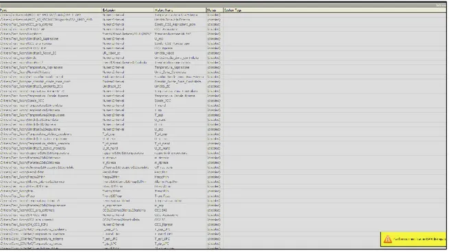
26 The values measured with the probes are the inputs of the supervisory system (COACH AX of CentraLine by Honeywell) to manage the technological plants and reproduce the boundary conditions for testing SIVeMeC prototype. The supervisor system has been completely designed and realised in the present PhD thesis.
COACH AX is a “one-tool” solution for engineering and managing all AX-based system components, which mainly are the ARENA AX supervisor, the integration controller HAWK and all I/O modules (see Figure 12). COACH AX allows building an application using the “wire sheet” format for creating the control logic and represents a tool to configure the graphical user interface for the ARENA AX supervisor and the HAWK controller as well as for the trend, schedule and alarm of all components [24].
The main features are:
Supervisor engineering (ARENA AX) – is a BACnet certified web-based supervisor utilizing the NiagaraAX Framework for small to big size systems. It is used to supervise HVAC systems and non-HVAC systems (e.g. lighting, security, life safety) in a building or across multiple buildings. ARENAAX serves real time graphical information to standard web-browser clients and also provides server-level functions such as: centralized data logging, archiving, alarming, real time graphical displays, master scheduling, system-wide database management, and integration with enterprise software applications [25].
Integration plant controller engineering (HAWK) – is a certified compact platform utilizing the NiagaraAX Framework. It combines integrated control, supervision, data logging, alarming, scheduling and network management functions with internet connectivity and web serving capabilities in a compact device. HAWK allows the control and management of external devices over the internet and present real-time information to users in web-based graphical views [26].
User-specific templates – all elements (e.g. web graphics, logic, devices) within a station can be stored in a library and easily reused.
Export tags – elements within HAWK, which should be exposed to several supervisors, can be tagged to avoid double engineering on controller and supervisor level. The tagged elements will be exposed automatically when the HAWK joins the supervisor. Input/output configuration modules – special views for fast configuration and start-up
27 Each measured point is a virtual point in the ARENA AX and allows designing the control logic of the laboratory plants.
The first stage of supervisory system programming was the writing of the regulation logics of the plants at service of the climatic rooms. Particularly, it was needed to configure all the measuring points described above and wrote the algorithms for the control of desired thermo-hygrometric parameters. In Figure 15 an example is reported of the “wire sheet” to create the control logic for managing the technological plants.
In order to make user-friendly the system and simplify its handling, different user-interface pages were created. Figure 16 shows one of these pages in which all the command and measuring point of the plants are reported to reproduce the boundary conditions in both external and confined environment.
By clicking the SET button it is possible to change the design value of the correspondent parameter, while TREND button shows the real-time trend of the selected parameter. Other variables have no button on its side, in this case that parameter is a component STATUS.
Figure 15: “wire sheet” programming for the control logic design.
The installed probes, in addition to return the desired measurements, also give an electrical output as 0 – 10 V and/or 4 – 20 mA. In this way, it is possible to design the suitable regulation logics of the actuators and those machines which have a modulating behaviour like the fan-coil solenoid valve and the immersed electrodes humidifier in the external environment climatic room.
28
Figure 16: user-interface for the managing of the climatic rooms conditions.
Humidifier in Figure 4 can modulate the steam flow rate in the range 0 – 8 kg/h by using a proportional external signal. This regulation occurs through two probes. To better explain why we need two different sensors it is worth remembering that, when the mechanical ventilation system works, an airflow rate of the same magnitude of that suctioned by SIVeMeC is replaced from the outside into the external climatic room. However, in the early stage of testing procedure, it is not convenient turn on SIVeMeC, but it is better uniformly reproduce the desired conditions in the room and exploit its thermal inertia. Hence, in the start-up stage a T-RH (Temperature – Relative Humidity) probe located in the room is used, while, after this initial transitory, the humidifier control system is retrofitted by a T-RH installed on the suction duct (see Figure 5).
The actuator used to adjust the water flow rate supplied in the fan-coil (see Figure 6) handle a three-way valve with a proportional signal. This retrofit is done, for the same reason explained above, by the RH probe in the climatic room during the early stage and the suction duct T-RH probe during the second stage.
It is now clear that the control and regulation of the same device could be done with different probes depending on the test stage: generally, the probes located inside the rooms are used during transitory phase; the probe installed on ducts are used during regime phase. To do that automatically, virtual switch inside ARENA AX were programmed. The shift happens when all set conditions occur simultaneously. However, it is possible also to force it manually.
29
Figure 17: SIVeMeC user-interface for control and managing.
Figure 18: SIVeMeC heat-pump user-interface.
To acquire and read all the data measured from the field (laboratory probes and devices), it is possible to set what to show of each variable and the sampling time.
30 Others user-interface pages are developed for control and manage the principal component of SIVeMeC. To connect the prototype to the supervisory system, SIVeMeC is equipped with a BMS (Building Management System) serial board installed on its electronic board. The communication protocol is standard Modbus. In this way, all the variables for the correct working of the mechanical ventilation system (see section 2.4) could be shown into supervisory system platform. Particularly, only a set of variables of interest are selected and used for remote control of the unit. Figure 17 shows the principal variables of mechanical ventilation system during its operation. Particularly these parameters mainly describe the system focusing on the “air-side”. On the contrary, Figure 18 largely deals with heat pump and inverter operation. To better visualize in an aggregate mode all the variables of interest and where they act in the laboratory, a graphic page is realized (Figure 19).
Figure 19: schematic laboratory user-interface page.
Figure 19 gives at first sight all the primary information about the mechanical ventilation system and the climatic rooms. Particularly, we can see the flow rate and thermo-hygrometric conditions of both supply and exhaust air, the compressor behaviour, the static heat exchanger efficiency, the thermo-hygrometric conditions in the climatic rooms and top-right COPs (Coefficient of Performance of the overall system: see section 3.2). Figure 19 represents a schematic user-interface page of the laboratory during winter test. An analogue page is developed for summer test.
31 As it easy to deduce, the supervisory system is a programmable platform and new control logics and other user-interface could be designed.
Finally, a “history page” (Figure 20) allows to select which variable we want to log. For each variable we could acquire 500 recordings, so the test length is a function of the sampling time (about 40 minutes with 5 s time step acquisition).
Figure 20: history page to select the variables of interest for historicization.
2.3 System configuration
SIVeMeC is the prototype with a static heat exchanger with the integration of a reverse-cycle heat pump machine (Figure 21) whose main components are:
a countercurrent heat exchanger able to ensure the highest possible static recovery; fans which speed is modulated by an inverter;
a compressor for modulation of the thermal load; an expansion valve for superheating management;
a programmable control unit to control the summer and winter configurations.
All SIVeMeC components and their sizing occurred through a suitable energy analysis. In fact, it is not sufficient rely on single device manufacturer performance declaration. The real efficiency must be validated when each component is connect to the others in the final system. To choose the appropriate size and test its suitability for the high performance of the system several energy parameters were evaluated (see section 3.2).