The Relative Position of RyR Feet and DHPR Tetrads
in Skeletal Muscle
Cecilia Paolini
1,2*, Feliciano Protasi
2and Clara Franzini-Armstrong
21University of Pennsylvania Department of Cell & Developmental Biology Philadelphia, PA 19104-6058 USA
2Ce.S.I., Center for Research on Ageing, University G.
d’Annunzio, Laboratory of Cellular Physiology, 66013 Chieti, Italy
In skeletal muscle, L-type calcium channels (or dihydropyridine receptors, DHPRs) are coupled functionally to the calcium release channels of the sarcoplasmic reticulum (or ryanodine receptors, RyRs) within specialized structures called calcium release units (CRUs). The functional linkage requires a specific positioning of four DHPRs in correspondence of the four identical subunits of a single RyR type 1. Four DHPRs linked to the four binding sites of the RyR1 cytoplasmic domain (or foot), define the corners of a square, constituting a tetrad. RyRs self-assemble into ordered arrays and by associating with them, DHPRs also assemble into ordered arrays. The approximate location of the four DHPRs relative to the four identical subunits of a RyR-foot can be predicted on the basis of the relative position of tetrads and feet within the arrays. However, until recently one vital piece of information has been lacking: the orientation of the two arrays relative to one another. In this work we have defined the relative orientation of the RyR and DHPR arrays by directly superimposing replicas of rotary shadowed images of rows of feet, obtained from isolated SR vesicles, and replicas of tetrad arrays obtained by freeze-fracture. If the orientation for the two sets of images is carefully maintained, the superimposition provides specific constraints on the DHPR–RyR relative position.
q2004 Elsevier Ltd. All rights reserved.
Keywords: calcium release units; dihydropyridine receptors; excitation– contraction coupling; ryanodine receptors; skeletal muscle
*Corresponding author
Introduction
In muscle cells, the ryanodine receptors (RyRs), or Ca2C release channels of the sarcoplasmic reticulum (SR), and the voltage-sensing L-type Ca2C channels of the plasmalemma (dihydropyr-idine receptors, DHPRs) occupy junctional domains of the sarcoplasmic reticulum (SR) and of the surface membrane/T tubules, respectively. These two junctional domains are closely apposed to form calcium release units (CRUs), i.e. sites at which the depolarization of the plasmalemma is transduced into a release of calcium from the SR in a mechanism known as excitation–contraction (e–c) coupling.1,2The skeletal muscle-specific isoforms of
the two proteins, RyR1 and a1SDHPR, are
structurally and functionally linked to each other within the apposed junctional domains of CRU.3–5 This allows bidirectional inter-molecular signaling by which each channel regulates the function of the other.6,7
The cytoplasmic domains of RyRs (also called feet) are clearly visible in thin sections of intact muscle, in shadowed images of isolated SR vesicles and in negatively stained images of the purified protein.3,8–11 RyR1s have an innate ability to assemble into orthogonal arrays both in vivo12,13 and in vitro11 independently of DHPRs’ presence. Since the large cytoplasmic domains of the RyRs, or feet, are in close contact with one another within the arrays, while the intra-membrane domains lie at some distance from each other, it is likely that an interaction between the cytoplasmic domains is responsible for the assembly of RyR1 into arrays.
DHPRs are detected in freeze-fracture images as large intra-membranous particles in the cyto-plasmic leaflet of the fractured surface membrane and/or transverse (T) tubules, that is in the membrane leaflet which is in contact with the
cytoplasm.3 When four DHPRs occupy four
0022-2836/$ - see front matter q 2004 Elsevier Ltd. All rights reserved.
Abbreviations used: CRU, calcium release unit; DHPR, dihydropyridine receptor or L-type Ca2Cchannel; e–c coupling, excitation–contraction coupling; RyR, ryanodine receptor or SR Ca2Crelease channel; SR, sarcoplasmic reticulum; T tubules, transverse tubules; EM, electron microscopy.
E-mail address of the corresponding author: [email protected]
in the RyR1 null myotubes.5,14 Furthermore, the RyR–DHPR linkage requires the skeletal isoform of both components. Indeed, RyR2 and RyR3, the two other known RyR isoforms, fail to restore DHPR arrays in RyR1 null myotubes that express a1SDHPR.14,15
The structures of both RyR and DHPR have been defined at an intermediate level of resolution: RyR1 is a homotetramer and its four subunits form a structure with a 4-fold rotational symmetry. The structure of the large cytoplasmic domains has been defined using electron microscopy and single particle analysis at a fairly high degree of resol-ution.16–19 Each of the four equal subunits is composed of multiple domains that are not equally disposed relative to the subunit’s axis. This results in a handedness of the whole cytoplasmic domain, so that its two mirror images are not superimpo-sable. The structure of DHPRs has been also determined at low resolution in shadowed images20 and at an intermediate level of resolution using cryo-electron microscopy.21–23 The DHPR is an asymmetric molecule with two large domains, each presumably containing one of the two large subunits (a1and a2) and one or more of the smaller subunits (b, g, and d).
Modeling of the RyR–DHPR interaction is strongly dependent on precise knowledge of their relative disposition within the arrays. A good deal of information is already available in this regard. RyR arrays have a handedness, that is to say mirror images of the arrays are not equal. This is due both to the inherent handedness of the RyR’s cyto-plasmic domains and to the fact RyRs are arranged so that the square delineating the cytoplasmic domains, or feet, are skewed relative to the lines connecting their centers.10 Since tetrad arrays are linked to RyR arrays, they also have a handedness and the squares delineating them are skewed.24 In addition, DHPR tetrads are associated with alter-nate feet. This disposition is well conserved in skeletal muscles through the vertebrates, the arrangements of feet and tetrads being exactly the same from bony fish to mammals.3,25
For an exact superimposition of the two arrays, one must know the orientation of both. Freeze-fracture replicas offer a one-sided view of DHPR arrays and thus contain unique information regard-ing the positions of individual DHPRs in tetrads
the handedness of the RyR arrays and the long axis of T tubules as a fiduciary marker for aligning arrays of tetrads with arrays of feet, we have been able to closely predict how the two arrays are related to each other. Our results are in agreement with recently published data obtained using EM tomography and showing the reconstruction of the entire triad.26
Results
Arrays of DHPR tetrads and of RyR feet were visualized using different preparation techniques. Ultimately, superimposition of the two arrays was made possible by sets of images from freeze-fractures of T tubules/plasmalemma for DHPRs and from replicas of freeze-dried, rotary shadowed isolated SR vesicles for RyRs.Figure 1illustrates the two techniques and shows the relative orientations of platinum shadowed carbon replicas from both preparations (see Materials and Methods for further details).Figure 1(a) illustrates the preparation and shadowing of isolated SR vesicles. Dark gray ovals represent RyRs subunits: large ones for the cyto-plasmic domains (constituting the feet) and small ones for the intra-membrane domains. Only two of the four identical subunits are shown for each foot. Figure 1(b) illustrates the process of freeze-fractur-ing the T tubule membrane and applies equally well to fractures of the plasmalemma at sites of peripheral couplings. The DHPRs are represented by pale gray, kidney-shaped structures, and the RyRs subunits by gray ovals. During freeze-frac-ture, an intra-membranous particle is generated where the fracture plane encounters a DHPR, and four of these particles are seen as a tetrad. Replicas of the two preparations, showing the T tubules’ (or plasmalemma’s) cytoplasmic leaflets and the feet bearing surfaces of the isolated SR vesicles are mounted on the grid to be observed in the electron microscope. The views of the RyRs and DHPRs thus obtained have the same orientation relative to each other and can thus be superimposed.
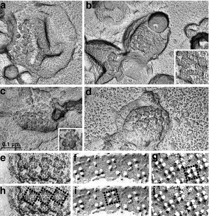
Rotary shadowing of isolated SR vesicles allows visualization of small arrays of feet that maintain the in situ disposition (Figure 2). Feet appear as groups of four approximately spherical and equal subunits projecting over the cytoplasmic surface of
the vesicles (Figure 2(c), inset). Where two or more feet are adjacent to each other, their outlines are in close contact over approximately one-third of the foot outline, just as in the in situ images (compare Figure 2(a)–(e) with Figure 17 of Ferguson et al.10). The orientation of the vesicle replicas inFigure 2(a) and (b) has been carefully preserved in the microscope (see Materials and Methods). Note that if one focuses attention on an individual foot profile, the four feet adjacent to it are seen to interact, sequentially, with the upper right corner, the upper left corner, the lower left corner and the lower right corner, on the four different sides of the squared outline of the foot. A definite handedness can be seen in the relationship between adjacent feet, creating the impression of a counterclockwise rotation, even though in these images the inherent handedness of the feet themselves is not resolved. Figure 2(c)–(e) illustrates vesicles from a previous project,10in which the orientation of the EM grid in the microscope was not considered. The appro-priate orientation for these images was deduced by comparison with the established orientation of Figure 2(a) and (b).
Once the handedness of the feet arrays is determined (as shown inFigure 2(a)–(d)), it can be compared with that of tetrads, provided that the orientation of the two arrays in the plane of the image is determined. The elongated shapes of junctional T tubule and SR domains, in which the tetrads and RyRs are located, provide specific constraints to the orientation of the arrays in the X–Y plane. This information has been published3 and has also been used to define the orientation of tetrad arrays that are present in the plasmalemma
of differentiating cells of the skeletal muscle lineage both in vivo and in vitro.4,14,15,25
Figure 2(e)–(f) and (j) compares arrays of feet and tetrads at the same magnification and with the same relative orientation. Figure 2(h)–(i) and (g) shows the same images, with either three feet or a single tetrad outlined. The handedness of the feet (RyR) array (Figure 2(e)) results from a defined skew of the outer profiles of the feet (see the square outline superimposed on three feet in Figure 2(h)) relative to the line connecting the centers of feet, and the long axis of the junctional SR, which is horizontal in the images. Figure 2(f) and (j) shows arrays of tetrads in the T tubule of a fish (f) and in the plasmalemma (j) of a cell from the BC3H1 mouse-derived line,27 that expresses skeletal muscle-specific CRU proteins (j).28 The T tubule provides a directional clue for the alignment of tetrads relative to feet,3 which is useful in the proper alignment of the tetrad array from the plasma-lemma.25 Note that the tetrad particles appear larger in the mouse (j) than in the fish (f) because the shadow is heavier in the former. However, the array parameters (inter-tetrad spacing and tetrad skew) are the same in the two samples, so that both fish and mouse tetrads are equally appropriate for comparison with mouse RyRs, as published.3,25 Tetrads are skewed, but their skew angle is distinctly different from that of the feet (square outline inFigure 2(i) and (g)).
The images of tetrads and feet shown inFigure 2 give essential information, but they cannot be directly superimposed with the necessary degree of accuracy because the membranes of both T tubules and isolated SR vesicles have considerable and not necessarily matching curvatures. For the
Figure 1.Diagrams illustrating some of the steps involved in obtaining shadowed replicas of isolated junctional SR (jSR) vesicles (a) and freeze-fractured T tubules (b). (a) A crude preparation of isolated SR vesicles is obtained by homogenization and differential centrifugation (see Materials and Methods). jSR vesicles are identified by the feet (RyRs) on their surface. The vesicles are adhered to a mica surface, freeze-dried and rotary shadowed. Once mounted on the EM grids, the orientation of the carbon replicas of both preparations appears as it would to an observer viewing it from the T tubule lumen toward the junctional gap. (b) DHPRs in the T tubule membrane are represented by kidney-shaped structures. RyRs in the SR membrane are represented by large and small ovals. The fracture, indicated by the broken line, follows the center of the lipid bilayer and makes a large jump, usually in the direction of the T tubule lumen, wherever a DHPR is located. After fracturing, shadowing and digesting away the tissue, the platinum-shadowed carbon replica is mounted on the EM grid (lower left).
final step in matching tetrad to feet arrays, we used images of tetrad arrays from BC3H1 cells, in which junctions between SR and plasmalemma almost perfectly flat.24 Figure 3(a) shows a small array of DHPR tetrads from such a junctional area, with clear evidence of order; larger arrays of the same type gave quite good optical diffraction patterns.24 In the case of Figure 3, the fracture was rotary
shadowed, so that each particle appears as a circular ring of platinum and the position of its peak (the pale central region) is well defined, albeit at a low level of resolution. In order to orient this array for comparison with an array of feet, first the centers of the tetrads are marked (Figure 3(b)), then the image is rotated (Figure 3(c)), so that the two rows of tetrads are in the same orientation as in
Figure 2.(a) and (b) Freeze-dried rotary shadowed jSR vesicles isolated from mouse muscle. The orientation has been preserved as indicated inFigure 1. In the inset in (b), the contact between feet is more visible. (c)–(e) and (h) jSR vesicles isolated from guinea pig muscle, showing well-preserved double rows of feet. The orientation of these images is obtained by comparison with (a) and (b). (e)–(j) Comparison between a double row of feet ((e) and (h) from guinea pig) and of tetrads ((f) and (i) from the T tubule of a toadfish muscle; (g) and (j) from the plasmalemma of a cultured, mouse derived BC3H1 cell). The three images are presented with the same orientation and at the same magnification. The size
and arrangement of tetrads is the same in fish and mouse (seeFigure 4). Squares delineate the outlines of feet and of tetrads in copies of the same images (g)–(i). In both cases, the squares are skewed relative to the long axis of the T tubule, but the skew for feet is distinctly different from that of the tetrads. The images of guinea pig vesicles show unpublished (c), (e) and (h) and published (d) micrographs from a previous project.10
Figure 2(f) and (j), mimicking the position along the T tubule axis. Finally, a few missing particles are added to complete the selected tetrads, and the particle positions are slightly adjusted to reduce the effect of distortion during fracturing (Figure 3(d)).
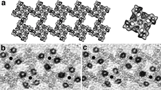
Figure 4 shows the results of superimposing
tetrad and foot arrays. A foot array modeling the two rows of feet of the junctional SR membrane apposed to T tubules (Figure 4(a)) was built using published outlines of the RyR cytoplasmic domains16,17 and positioning them in a manner that takes into consideration the well-defined
Figure 3.Rotary shadowed replica of a small DHPR tetrad array in a peripheral coupling from the mouse skeletal muscle cell line, BC3H1. Each particle, showing the location of one DHPR, is delineated by a dark ring of platinum. (a)
The pale center of the rotary shadowed particles clearly delineates the position of the highest peak of the fractured molecule and the particles are arranged in tetrads. In (b) the tetrad centers are dotted. In (c) the array is rotated, outlined and shown as it would appear within a short segment of a horizontally oriented T tubule. In (d) missing and/or faintly showing particles are added, in order to complete the array; particles belonging to other tetrads are eliminated and slight distortions are corrected (compare with (c)). Unpublished micrographs from a published project.25
Figure 4.Superimposition of foot and tetrad arrays. (a) Left: an array of feet was built using a 3D reconstruction of RyRs seen from the cytoplasmic side (from Serysheva et al.29). One side of each foot subunit was juxtaposed with those of
adjacent feet, with an offset of approximately one-third of the side of the foot. The skew of foot outlines in (a) is the same as inFigure 2(h). The positions of FKBP12 and CAM binding regions on the RyR subunits are indicated by asterisks and dots, respectively. Right: RyR subunit domains referred to in the text are indicated on the outline of a single RyR. (b) and (c) A semi-transparent copy of the tetrad array from (d) was scaled and superimposed on the foot array of (a) in two different ways. In (b) the centers of tetrads (filled circles) coincide with the centers of feet while in (c) the centers of tetrads lie along the same line as the centers of feet, but are located halfway between two of them along that line. (b) The correct arrangement, see the text.
Figure 4(b) and (c) shows two possible super-impositions of tetrad and foot arrays. In both cases, the lines joining the centers of feet and tetrads in the direction that is parallel to the T tubule axis are superimposed. However, inFigure 4(b) the centers of tetrads (filled black circles) are superimposed on the centers of alternate feet, while inFigure 4(c) they fall halfway between the centers of feet. Note that these are the only two possibilities for matching the two repeating structures, given the fact that the lines connecting the centers of feet and tetrads in the direction of the T tubule axis must be super-imposed (see above). The immediate observation is that in Figure 4(b), in which tetrads interact with alternate feet, each of the four tetrad subunits is in an equivalent position relative to the four equal foot subunits. InFigure 4(c), on the other hand, each of the four tetrad components has a different position relative to the foot subunits, and some DHPRs actually have no apparent connection to any RyR component. Thus, the sharing of tetrads by two adjacent feet (as shown inFigure 4(c)) is an unlikely possibility and will not be discussed further (see also Ferguson et al.3). Implications of the tetrad–feet relationship of Figure 4(b) for the RyR–DHPR interaction are dealt with in Discussion.
Discussion
The observations from this work provide fairly defined constraints on the relative positions of DHPRs and RyRs within Ca2Crelease units (CRUs), the structures deputed to excitation–contraction (e–c) coupling in muscle. A good fit is obtained by positioning the DHPR freeze-fracture particles close to, but not quite halfway, along the side of the square outline defining the foot (seeFigure 4). Note that previously published diagrams of feet and tetrad arrays14,24 differ from the one shown here, because they were incorrectly built without specific knowledge of the relative orientation of the two arrays.
Figure 5(a) and (b) shows two possible associ-ations of four DHPRs (each including all five subunits) with a single RyR, obtained by combining 3D reconstructions of the two molecules available in the literature.Figure 5(a) was built keeping in mind the relative positions of RyR and DHPR predicted
from the arrays ofFigure 2(g)–(j) (illustrated in the superimposition ofFigure 4(b)) and the overall 3D shape of RyR and DHPR.21,29 Figure 5(b) was constructed by Wolf et al.23 independently of the data shown here, but keeping in mind the tetradic arrangement of DHPRs. Note that in this latter image the RyR is the same as that shown inFigures 4(a) and 5(a), but details of RyR–RyR associations are slightly different. The differences are not very large and the general agreement between Figure 5(a) and (b) is due to the fact that given the size and shape of the RyRs and the four DHPRs, as well as their positions in the arrays, there is very little degree of freedom in their relative positioning. In both panels, the region of DHPR that has been suggested to contain the a2subunit,21,23falls in the approximate position of the freeze-fracture particle. However, the subunit identity of the DHPR freeze-fracture particle is not yet determined and thus it is not known whether the particle reflects the position of the a1or the a2 subunit. In the former case, the DHPR would have to be rotated in order to fit the freeze-fracture data.
While the two models of Figure 5 both fit the observed relationship between DHPR tetrads and RyRs, the dimeric arrangement of DHPR envisaged by Wang et al.30is not consistent with our data. The proposed dimeric DHPR would result in a much smaller tetrad than that observed here.
It has long been known that DHPR tetrads are associated with alternate feet.25An explanation for this unusual arrangement can be seen in both proposed RyR–DHPR assemblies (Figure 5(a) and (b)). In this Figure part of the DHPR is placed in the vicinity of the handle-shaped domains formed between regions 4 and 6 (marked in the single RyR outline of Figure 4(a)) in the cytoplasmic assembly of the RyR.16,31These portions correspond to the domains that lie nearest the T tubule membrane and that are spaced at the same distance
current 3D reconstructions of the two molecules, (see the text for details). Arrows indicate the probable position of the DHPR a2 subunit. Both images are
essentially in agreement with the overall tetrad–RyR relationship shown in this work, but differ in small, probably significant, details. (b) Reproduced with per-mission from Wolf et al.23
as the four components of a tetrad. In addition, however, a good part the DHPR mass is located in a position that is peripheral to the foot outline and that partially overlaps with the outline of adjacent feet. This would result in a steric hindrance that would impede formation of tetrads on immediately adjacent feet. However, this hindrance alone is not sufficient to explain why DHPRs are not associated with RyR subunits that are not directly affected by the close proximity of another DHPR.
A direct result of the larger size of tetrads relative to feet is that each DHPR may be able to be in contact with two adjacent RyRs. However, it must be noted that the two “contacts” between one DHPR and two adjacent RyRs would involve different domains of either molecule and thus, cannot be assumed to have the same function. Therefore, this possible contact of DHPR with the “uncoupled” feet cannot be considered to serve as a means of activating them by the mechanism that activates the “coupled” feet. In addition, the steric hindrance alone is not sufficient to explain why DHPRs are exclusively associated with the subunits of adjacent feet, even when the tetrads are incom-plete due to a low overall DHPR/RyR ratio.24
The RyR array of Figure 4(a) allows specific predictions regarding which regions of adjacent RyRs are in proximity and perhaps in direct contact to each other. Ligand binding domains of the RyR foot region have been quite precisely located within the three-dimensional structure of the molecule. The prediction is that FKBP12 and Ca2C-CaM and apoCaM (marked by asterisks and dots, respect-ively, inFigure 4(a)) bind at the two opposite ends of the domain labeled 3 of the cytoplasmic region of the RyR.31–33In the array, the FKBP12, Ca2C-CaM and apoCaM are not shared between two adjacent feet and may not directly contribute to the protein– protein interaction.31,32,34
These images set the stage for the final step in understanding of the specific relationship between DHPRs and RyRs that allows them to exchange reciprocal talk. A further increase in resolution will be sufficient to predict the final molecule-to-molecule fit, within the constraints imposed by their overall 3D arrangement.
Materials and Methods
Preparation of striated muscle membranes
Muscle from the hind legs of young adult mice was finely minced in a solution containing 5 mM EGTA, 10 mM DL-histidine, and a protease inhibitor cocktail
(Roche Diagnostics GmbH, Mannheim, Germany) and an additional 0.1 mM of leupeptin (see also Ferguson et al.10). A 0.5 g muscle/5 ml of solution was homogenized in a Tekmar Tissumizer (Tekmar Cop., Cincinnati, Ohio) at maximum speed for three to four times at two seconds intervals and centrifuged at 1800g for ten minutes at 4 8C. The supernatant was centrifuged at 18,000g for ten minutes in an Eppendorf microfuge and the pellet re-suspended in a small volume of the same solution. In
some experiments the second supernatant was centri-fuged again at 18,000g for 25 minutes in an Eppendorf microfuge. The final pellet of crude SR was re-suspended in the initial solution. The suspension was used immedi-ately for rotary shadowing, and the remaining portion, supplemented with 250 mM sucrose solution, was frozen in liquid nitrogen and stored at K80 8C. A similar procedure was used for the guinea pig SR vesicles.10 Electron microscopy
Freeze fracture of muscles and cultured cells
The lateral band muscles from the toadfish (Opsanus tau) swim bladder were fixed by perfusion through the major artery with 6% (v/v) glutaraldehyde in 0.1 M cacodylate buffer (pH 7.2).3 Cultured 1B5 cells were
briefly rinsed in phosphate-buffered saline (PBS), fixed in 3.7% glutaraldehyde in 0.1 M sodium cacodylate buffer and kept in fixative for up to one to four weeks before further use.24 For the freeze-fracture the tissues were
infiltrated with 30% (v/v) glycerol. A small piece of cover slip was mounted with the cells facing a droplet of 30% glycerol, 20% (v/v) polyvinyl alcohol on a gold holder and frozen in liquid nitrogen-cooled propane.35 The fractured surfaces were shadowed with platinum either at 458 unidirectionally or at 258 while rotating, and replicated with carbon in a freeze-fracture apparatus (model BFA 400; Balzers S.p.A., Hudson, NH).
Freeze-drying and replication of isolated SR vesicles Isolated vesicles were adsorbed to either freshly split mica or carbon-coated glass, rinsed with 100 mM ammonium acetate, treated with 2% (w/v) uranyl acetate for 30–60 seconds and rinsed extensively with 30% (v/v) methanol.10 The solution was dried to a very thin film using filter paper for the mica or the sandwich technique for glass36and frozen in liquid nitrogen. The vesicles were freeze-dried at 10K6mbar of pressure and a temperature
of K90 8C for at least 30 minutes, and then re-cooled to K110 8C, rotary shadowed with Pt at a 258 angle and replicated with carbon.
Microscopy
Replicas were viewed and photographed in an electron microscope Philips EM 410 (Philips Technologies, Che-shire, CT). Care was taken in mounting the grid upside down in the microscope (with the underside of the grid facing the electron beam). Turning the negative’s gelatin side down when photographically printing and/or positioning the negative with the gelatin side opposite to the illumination when digitally scanning rectifies this inverted image.
Acknowledgements
We thank N. Glaser for continued help in this work and Diane E. Sagnella for her critical reading of the manuscript. We also thank S. L. Hamilton and I. Serysheva for the 3D reconstructions of both RyR and DHPR. This work was supported by NIH grant PO1AR17605.
Franzini-Armstrong, C. (1994). Restoration of junc-tional tetrads in dysgenic myotubes by dihydropyri-dine receptor cDNA. Biophys. J. 67, 793–804.
5. Protasi, F., Franzini-Armstrong, C. & Allen, P. D. (1998). Role of ryanodine receptors in the assembly of calcium release units in skeletal muscle. J. Cell Biol. 140, 831–842.
6. Nakai, J., Tanabe, T., Konno, T., Adams, B. & Beam, K. G. (1998). Localization in the II–III loop of the dihydro-pyridine receptor of a sequence critical for excitation– contraction coupling. J. Biol. Chem. 273, 24983–24986. 7. Grabner, M., Dirksen, R. T., Suda, N. & Beam, K. G. (1999). The II–III loop of the skeletal muscle dihy-dropyridine receptor is responsible for the Bi-direc-tional coupling with the ryanodine receptor. J. Biol. Chem. 274, 21913–21919.
8. Franzini-Armstrong, C. (1970). I. Structure of the junction in frog twitch fibers. J. Cell Biol. 47, 488–499. 9. Saito, A., Seiler, S., Chu, A. & Fleischer, S. (1984). Preparation and morphology of sarcoplasmic reticu-lum terminal cisternae from rabbit skeletal muscle. J. Cell Biol. 99, 875–885.
10. Ferguson, D. G., Schwartz, H. & Franzini-Armstrong, C. (1984). Subunit structure of junctional feet in triads of skeletal muscle. A freeze-drying, rotary-shadowing study. J. Cell Biol. 99, 1735–1742.
11. Yin, C. C. & Lai, F. A. (2000). Intrinsic lattice formation by the ryanodine receptor calcium-release channel. Nature Cell Biol. 2, 669–671.
12. Takekura, H., Takeshima, H., Nishimura, S., Imoto, K., Takahashi, M. Tanabe, T. et al. (1995). Co-expression in CHO cells of two muscle proteins involved in excitation contraction coupling. J. Muscle Res. Cell Motil. 16, 465–480.
13. Takekura, H., Nishi, M., Noda, T., Takeshima, H. & Franzini-Armstrong, C. (1995). Abnormal junctions between surface membrane and sarcoplasmic reticu-lum in skeletal muscle with a mutation targeted for the ryanodine receptor. Proc. Natl Acad. Sci. USA, 92, 3381–3385.
14. Protasi, F., Takekura, H., Wang, Y., Chen, S. R. W., Meissner, G., Allen, P. D. & Franzini-Armstrong, C. (2000). RYR1 and RYR3 have different roles in the assembly of calcium release units of skeletal muscle. Biophys. J. 79, 2494–2508.
15. Protasi, F., Paolini, C., Nakai, J., Beam, K. J., Franzini-Armstrong, C. & Allen, P. D. (2002). Multiple regions of RYR1 mediate functional and structural inter-actions with a1s DHPR in skeletal muscle. Biophys. J. 83, 3230–3244.
16. Radermacher, M., Rao, V., Grassucci, R., Frank, J., Timerman, A. P., Fleischer, S. & Wagenknecht, T. (1994). Cryo-electron microscopy and
three-46712–46719.
20. Leung, A., Imagawa, T., Block, B., Franzini-Armstrong, C. & Campbell, K. P. (1988). Biochemical and ultrastructural characterization of the 1,4-dihydropyridine receptor from rabbit skeletal muscle. Evidence for a 52,000 subunit. J. Biol. Chem. 263, 994–1001.
21. Serysheva, I. I., Ludtke, S. J., Baker, M. R., Chiu, W. & Hamilton, S. L. (2002). Structure of the voltage-gated L-type Ca2C channel by electron cryomicroscopy. Proc. Natl Acad. Sci. USA, 99, 10370–10375.
22. Wang, M. C., Velarde, G., Ford, R. C., Berrow, N. S., Dolphin, A. C. & Kitmitto, A. (2002). 3D structure of the skeletal muscle dihydropyridine receptor. J. Mol. Biol. 323, 85–98.
23. Wolf, M., Eberhart, A., Glossmann, H., Striessnig, J. & Grigorieff, N. (2003). Visualization of the domain structure of an L-type Ca2C channel using electron cryo microscopy. J. Mol. Biol. 332, 171–182.
24. Protasi, F., Franzini-Armstrong, C. & Flucher, B. (1997). Coordinated incorporation of skeletal muscle dihydropyridine receptors and ryanodine receptors in peripheral couplings of BC3H1 cells. J. Cell Biol. 137,
859–870.
25. Franzini-Armstrong, C. & Kish, C. W. (1995). Alter-nate disposition of tetrads in peripheral couplings of skeletal muscle. J. Muscle Res. Cell Motil. 16, 19–324. 26. Wagenknecht, T., Hsieh, C. E., Rath, B. K., Fleischer, S.
& Marko, M. (2002). Electron tomography of frozen-hydrated isolated triad junctions. Biophys. J. 83, 2491–2501.
27. Schubert, D., Harris, A. J., Devine, C. E. & Heinemann, S. (1974). Characterization of a unique muscle cell line. J. Cell Biol. 61, 398–413.
28. Marks, A. R., Taubman, M. B., Saito, A., Dai, Y. & Fleischer, S. (1991). The ryanodine receptor/junc-tional channel complex is regulated by growth factors in a myogenic cell line. J. Cell Biol. 114, 303–312. 29. Serysheva, I. I., Orlova, E. V., Chiu, W., Sherman, M. B.,
Hamilton, S. L. & van Heel, M. (1995). Electron cryomicroscopy and angular reconstruction used to visualize the skeletal muscle calcium release channel. Struct. Biol. 2, 18–24.
30. Wang, M.-C., Velarde, G., Ford, R. C., Berrow, N. S., Dolphin, A. C. & Kitmitto, A. (2002). 3D structure of the skeletal muscle dihydropyridine receptor. J. Mol. Biol. 323, 85–98.
31. Wagenknecht, T., Radermacher, M., Grassucci, R., Berkowitz, J., Xin, H. B. & Fleischer, S. (1997). Locations of calmodulin and FK506-binding protein on the three dimensional architecture of the skeletal muscle ryanodine receptor. J. Biol. Chem. 272, 32463–32471.
and Ca2C-calmodulin bind to neighboring locations
on the ryanodine receptor. J. Biol. Chem. 277, 1349–1353.
33. Hamilton, S. L., Serysheva, I. I. & Strasburg, G. M. (2000). Calmodulin and excitation-contraction coupling. News Physiol. Sci. 15, 281–284.
34. Wagenknecht, T. & Samso, M. (2002). Three-dimen-sional reconstruction of ryanodine receptor. Front. Biosci. 7, d1464–d1474.
35. Osame, M., Engel, A. G., Rebouche, C. J. & Scott, R. E. (1981). Freeze-fracture electron microscopic analysis of plasma membranes of cultured muscle cells in Duchenne dystrophy. Neurology, 31, 972–979.
36. Loesser, K. E. & Franzini-Armstrong, C. (1990). A simple method for freeze-drying of macromolecules and macromolecular complexes. J. Struct. Biol. 103, 48–56.
Edited by W. Baumeister