This is an Accepted Manuscript, which has been through the
Royal Society of Chemistry peer review process and has been
accepted for publication.
Accepted Manuscripts are published online shortly after
acceptance, before technical editing, formatting and proof reading.
Using this free service, authors can make their results available
to the community, in citable form, before we publish the edited
article. We will replace this Accepted Manuscript with the edited
and formatted Advance Article as soon as it is available.
You can find more information about Accepted Manuscripts in the
Information for Authors
.
Please note that technical editing may introduce minor changes
to the text and/or graphics, which may alter content. The journal’s
standard
Terms & Conditions
and the
Ethical guidelines
still
apply. In no event shall the Royal Society of Chemistry be held
responsible for any errors or omissions in this Accepted Manuscript
or any consequences arising from the use of any information it
contains.
Accepted Manuscript
ChemComm
www.rsc.org/chemcomm
View Article OnlineView Journal
This article can be cited before page numbers have been issued, to do this please use: N. Moreno, M. Agostini, Á. Caballero, J. Morales and J. Hassoun, Chem. Commun., 2015, DOI: 10.1039/C5CC05162B.
Journal Name
COMMUNICATION
This journal is © The Royal Society of Chemistry 20xx J. Name., 2013, 00, 1-3 | 1
Please do not adjust margins
Please do not adjust margins
Received 00th January 2015,Accepted 00th January 2015 DOI: 10.1039/x0xx00000x
www.rsc.org/
A Long-life Lithium-ion Sulfur Battery exploiting High Performance
Electrodes
Noelia Moreno
a,‡, Marco Agostini
b,‡, Alvaro Caballero
a, Julián Morales*
aand Jusef Hassoun*
bA novel lithium-ion sulfur battery is formed by coupling activated ordered mesoporous carbon-sulfur (AOMC-S) cathode and a nanostructured tin-carbon anode. The lithium-ion cell has improved reversibility, high energy content and excellent cycle life.
The expected large-scale diffusion of hybrid electric vehicles (HEVs) and electric vehicles (EVs) triggered the fast development of advanced energy storage systems characterized by outstanding characteristics. Lithium-ion battery represented the most promising and appealing candidate to meet the market targets due to its high specific energy i.e., around 150 Wh kg−1. However, the lithium intercalation chemistry driving the present battery in portable electronics, scarcely meets the severe targets of the electric transportation field. New, high-energy systems are required to meet the requirements of the emerging electric automotive market.1,2 Lithium sulfur battery is considered the most suitable candidate to meet this target, in view of the high theoretical capacity of the sulfur cathode, i.e., 1675 mAh g−1, reflecting a theoretical specific energy as high as 2600 Wh kg-1. Furthermore, sulfur is an abundant, environmental friendly and low cost element, thus a suitable candidate in replacement of the lithium metal oxide materials used as the cathode in conventional lithium battery. However, several issues limit the practical use of the sulfur cathode in lithium cell, including low conductivity, remarkable volume changes and lithium polysulfide dissolution during the electrochemical process that lead to shuttle reactions, internal resistance increase and consequent cell failure.3,4 These drawbacks have been efficiently mitigated by developing mesoporous5-8 and
microporous9-11 carbon matrixes encapsulating sulfur12-14 to enhance the conductivity and decrease the solubility of the Li-S reaction products within the electrolyte.15 The severe polysulfide shuttle reaction affecting the lithium sulfur battery can be hindered by including a lithium nitrate salt within the electrolyte composition in order to form a stable layer at the lithium surface inhibiting this side process.16-21 The conventional Li-S battery combines usually sulfur cathode and lithium metal anode, in an organic liquid electrolyte. This simple configuration suffers, however, by possible dendrites formation at the metal surface and cell short-circuit during operation, with consequent safety hazards, possible heating and fire evolution.22,23 Indeed, the replacement of lithium metal by alternative, high capacity, anode materials, such as Li-alloying silicon (Si) and tin (Sn), appears very promising approach to enhance the cell safety.22 However, the use of alternative anodes that are generally within the lithium-free configuration, requires the employment of a discharged sulfur cathode, i.e. Li2S, instead of sulfur.
24-27
Li2S electrode is almost insulator and reactive with moisture, hence it requires particular care during preparation and manipulation. Therefore, the S-C cathode is the preferred choice in order to allow easy handling, in particular during electrode casting and preparation that may be performed under air. However, the employment of sulfur electrode, instead of Li2S, in full lithium-ion cell requires a lithium source that is efficiently provided by using pre-lithiated anode, such as LixSn or LixSi.28-30
In this work, we report a long life lithium ion battery employing a composite cathode formed by impregnating sulfur by chemical reduction into activated ordered mesoporous carbon (shortened by the acronym AOMC-S, see experimental part reported in the Supplementary Information (SI) section for preparation procedure).31 The carbon matrix enhances the electrode performances, mitigates its dissolution during cycling and allows a sulfur content as high as 60% w:w. The full cell, combining the AOMC-S cathode and a nanostructured tin carbon anode in its lithiated state, has a theoretical specific energy as high as 450 Wh kg-1 (See table 2 and discussion in the SI section for details). The cell practically operates, in
Page 1 of 3
ChemComm
ChemComm
Accepted
Manuscript
Published on 05 August 2015. Downloaded by KUNGL TEKNISKA HOGSKOLAN on 05/08/2015 13:37:56.
View Article Online
COMMUNICATION
Journal Name
2 | J. Name., 2012, 00, 1-3 This journal is © The Royal Society of Chemistry 20xx
Please do not adjust margins
Please do not adjust margins
average, at about 1.7 V and delivers a stable capacity of about 600 mAh g−1 over 300 cycles. These values allow the achievement of an estimated practical specific energy of about 280 Wh kg-1 (see SI section, Table 2 discussion). The high energy, in addition to the long cycle life, the low cost of the employed materials and the expected safety suggest the battery here reported as suitable candidate for advanced energy storage applications.
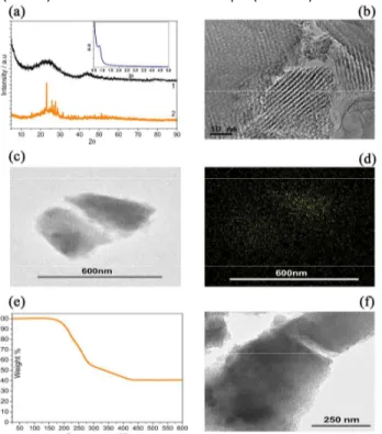
Fig. 1 reports the structural and morphological characteristics of the activated ordered mesoporous carbon (AOMC) and of the sulfur-loaded sample (AOMC-S).
Fig. 1 a) X ray diffraction patterns (XRD) of the AOMC precursor and
the AOMC-S composite and in inset SAXS of AOMC-S composite. b) HRTEM images of the AOMC precursor. c) STEM image, d) sulfur elemental mapping (EDX), e) TGA curve and f) TEM image of the AOMC-S composite.
The XRD pattern of the AOMC (Fig.1a, black line) shows two low intensity broad-peaks, at 24.5° and 43.4°, respectively, assigned to the (002) and (100) crystallographic planes of graphite. Furthermore, the XRD pattern of the AOMC-S sample (Fig.1a, orange line) still reveals the amorphous carbon profile and, in addition, well-defined peaks associated to the orthorhombic sulfur. The Small-Angle X-ray Scattering (SAXS) measurement reported in inset of Fig. 1a shows the presence of a peak at 0.84º 2θ (d = 10.5 nm), associated to porous ordering of the carbon. The high resolution transmission electron microscopy (HRTEM), Figures 1b, shows the typical stripe-like structure along [110] of the ordered mesoporous carbon and amorphization due to the OMC activation process. The morphology of the AOMC-S composite is evaluated by the scanning transmission electron microscopy (STEM) and the corresponding sulfur elemental mapping, as measured by energy dispersive X-ray spectroscopy (EDX), see Figures 1c and
d respectively. The images reveal homogeneous distribution of sulfur within the sub-micrometric carbon particles. The thermogravimetric curve of the AOMC-S sample recorded under N2 is shown in Fig. 1e, and illustrates a sulfur loss evolving through two consecutive steps between 180 °C and 425 °C. The first step, at the lower temperature, is due to the sulfur located at the external shell of the composite, while the second, at the higher temperature, is due to inner-S trapped into the bulk of the carbon.5 Despite creating partial disorder, the activation process leads to a surface area increase, revealed by Brunauer–Emmett–Teller (BET) (for details of the AOMC see SI section, Table 1). Indeed, Table 1 indicates a surface area of 1049 m2 g−1 and a pore volume of 0.88 cm3 g−1. These remarkable values allow a sulfur loading as high as 60% w:w, as indeed demonstrated by the TGA data of Fig. 1b, thus increasing the practical specific energy of the Li-S cell employing the AOMC-S electrode. On sulfur loading, the surface area and pore volume values drastically decreased (see Table 1). This result (i.e., a surface area below 1 m2 g-1) indicates that both mesoporous and microporous are filled by sulfur (see Fig. 1f). The above reported analysis suggests for the AOMC-S composite an easy electrons and ions transport, together with a mitigated sulfur dissolution during cycling, hence enhanced Li-S cell performances. Indeed, Figure 2a shows the galvanostatic cycling of the AOMC-S composite in lithium cell and being noteworthy the very stable capacity of about 650 mAh gs−1 over 100 cycles at 100 mA gs−1. The corresponding voltage profiles from the 1st to the 100th cycle, reported in Figure 2b, reveal a cycle characterized by two plateaus, at 2.3V and 2.1V, during discharge and merged plateaus at about 2.3V during charge, corresponding to the Li-S redox process. The reversible capacity, of about 750 mAh gs−1 during the first cycles, decreases to about 650 mAh gs-1 upon 100 charge discharge cycles, with a capacity retention of about 90% (Fig. 2a). The low charge-discharge polarization as well as the excellent capacity retention point to the enhanced characteristics of the AOMC-S electrode. The AOMC-S electrode is further characterized in lithium sulfur half-cell in terms of rate capability. Figures 2c and d, respectively, report the cycling behavior and the corresponding voltage profiles collected at increasing c-rates, i.e., 100, 200, 300, 500 and 1000 mA gs−1. The cell delivers a capacity of 900 mAh gs-1 at 100 mA gs−1 and a still high value of 550 mAh gs−1 at a current rate as high as 1000 mA gs−1, with a capacity retention of about 88% in respect to the maximum capacity by lowering back the current to the initial value (Fig.2c). In addition, the voltage profiles of Figure 2d show a limited increase of the cell polarization by rising the current from 100 to 500 mA gs−1 that becomes remarkable only at a current of 1000 mA gs
−1 . The excellent behavior in half-cell suggested the AOMC-S electrode as suitable cathode materials for application in a lithium-ion cell, in which lithium metal is replaced by an alternative anode characterized by higher safety content. In this work, we selected a nanostructured Li4Sn-C composite able to deliver a stable capacity of about 400 mAh g-1 as preferred anode (see cycling test in SI, Fig. S1).30 The electrochemical process of the
full cell is reported as following: 4Li4Sn-C+S8 ↔ 8Li2S+4Sn-C.
Page 2 of 3
ChemComm
ChemComm
Accepted
Manuscript
Published on 05 August 2015. Downloaded by KUNGL TEKNISKA HOGSKOLAN on 05/08/2015 13:37:56.
View Article Online
Journal Name
COMMUNICATION
This journal is © The Royal Society of Chemistry 20xx J. Name., 2013, 00, 1-3 | 3
Please do not adjust margins
Please do not adjust margins
Fig. 2 Electrochemical characteristics of Li/DME:DOL(1:1), LiTFSI 1M,
LiNO3 0.4M/AOMC-S half-cell: a) cycling behavior at a current of 100
mA gs-1; b) corresponding voltage profile; c) rate capability
measurement and d) corresponding voltage profiles performed at a current of 100; 200; 500 and 1000 mA gs
−1
, respectively. Voltage limits: 1.9−2.8V. Temperature 25oC.
Figure 3 reports the galvanostatic response of the Li-ion cell cycled using a current of 300 mA gs
−1 .
Fig. 3 a) 2nd
to 10th
voltage profiles and long term cycling behavior b) of the Li4Sn-C/DME:DOL (1:1) LiTFSI 1M, LiNO3 0.4M/AOMC-S lithium ion
cell. Voltage limits: 1–3V. Current-rate 300mA gs−1. Temperature 25oC. The steady state voltage profiles of the cell reported in Figure 3a (see first cycle in Fig. S2 in SI section) reflect the combination of the two plateau of the Li-sulfur cell (compare with Fig.2) and the sloppy-shape profile of the Li-Sn-C.28,30 The cell operates within 1V and 3V, with an average working voltage of about 1.7V, a capacity of about 600 mAh gs
−1 for over 300 cycles and a Coulombic efficiency approaching 100%. Comparing to the cycling response of the sulfur half-cell in Fig. 2, the full cell shows a reduction of the capacity of about 25%, at the same current rate (300 mA g-1). This reduction may be ascribed to a higher discharge cutoff in respect to one corresponding to the full discharged state of the cell.
In this work, we studied an advanced Li-ion cell formed by the combination of a high performance sulfur cathode exploiting an activated ordered mesoporous carbon matrix (AOMC-S) and a lithiated tin-carbon nanostructured anode (Li4Sn-C). The excellent cycle life in addition to an estimated practical energy of about 280 Wh kg-1 indicate the cell here reported as competing candidate in respect to the technology
presently available (see SI section and Table 2 discussion).26 Additional bonuses of our cell are the expected high safety content due to the replacement of the Li-metal anode with nanostructured Li-Sn-C alloy, and the low cost of the raw materials, thus suggesting it as a very promising energy storage system.
References
1 J.-M. Tarascon, M. Armand, Nature, 2001, 414, 359. 2 B. Scrosati, J. Garche, J. Power Sources, 2010, 195, 2419. 3 Y. Yang, G. Zheng, Y. Cui, Chem. Soc. Rev., 2013, 42, 3018. 4 A. Manthiram, Y. Fu, S. Chung, C. Zu, Y. Su., Chem. Rev.,
2014, 114, 11751.
5 X. Ji, K.-T. Lee, L.-F. Nazar, Nat. Mater., 2009, 8, 500. 6 Y. Yang, G. Yu, J.-J. Cha, H. Wu, M. Vosgueritchian, Y. Yao, Z.
Bao, Y. Cui, ACS Nano, 2011, 5, 9187.
7 J. Kim, D.-J. Lee, H.-G. Jung, Y.-K. Sun, J. Hassoun, B. Scrosati,
Adv. Funct. Mater., 2012, 23, 1076.
8 N. Moreno, A. Caballero, L. Hernan, J. Morales, J. Canales-Vazquez, Phys. Chem. Chem. Phys., 2014, 16, 17332. 9 S. Zhao, C. Li, W. Wang, H. Zhang, M. Gao, X. Xiong, A. Wang,
K. Yua, Y. Huang, F. Wang, J. Mater. Chem.A, 2013, 1, 3334. 10 X. Wang, X. Fang, X. Guo, Z. Wang, L. Chen, Electrochim.
Acta, 2013, 97, 238.
11 N. Moreno, A. Caballero, L. Hernan, J. Morales, Carbon, 2014, 70, 241.
12 S. Zheng, Y. Chen, Y. Xu, F. Yi, Y. Zhu, Y. Liu, J. Yang, C. Wang,
ACS Nano, 2013, 7, 10995.
13 J. Guo, Z. Yang, Y. Yu, H.-D. Abruña, L.-A. Archer, J Am. Chem.
Soc., 2013, 135, 763.
14 Z. Yang, J. Guo, S.-K. Das, Y. Yu, Z. Zhou, H.-D. Abrua, L.-A. Archer, J. Mater. Chem. A, 2013, 1, 1433.
15 S. Zhang, J. Power Sources, 2013, 231, 153.
16 S. Xiong, K. Xie, Y. Diao, X. Hong, Electrochim. Acta, 2012, 83, 78.
17 D. Aurbach, E. Pollak, R. Elazari, G. Salitra, C.-S. Kelley, J. Affinito, J. Electrochem. Soc., 2009, 156, A694.
18 C. Barchasz, J.-C. Leprêtre, F. Alloin, S. Patoux, J. Power
Sources, 2012, 199, 322.
19 M. Agostini, D.-J. Lee, B. Scrosati, Y.-K. Sun, J. Hassoun, J.
Power Sources, 2014, 265, 14.
20 L. Carbone, M. Gobet, J. Peng, M. Devany, B. Scrosati, S. Greenbaum, J. Hassoun, ACS Appl. Mater. Interfaces, 2015, 7, 13859.
21 X. Liang, Z. Wen, Y.Liu, M. Wu, J. Jin, H. Zhang, X. Wu, J.
Power Sources, 2011, 196, 9839.
22 H. Kim, G. Jeong, Y. Kim, J. Kim, C. Park, H. Sohn, Chem. Soc.
Rev., 2013, 42, 9011.
23 A. Zhamu, G. Chen, C. Liu, D. Neff, Q. Fang, Z. Yu, W. Xiong, Y. Wang, X. Wang, B.Z. Jang, Energy Environ. Sci., 2012, 5, 5701. 24 J. Hassoun, B. Scrosati, Angew. Chem. Int. Ed., 2010, 49,
2371.
25 J. Hassoun, Y.-K. Sun and B. Scrosati, J. Power Sources, 2011, 196, 343.
26 Y. Yang, M.-T. McDowell, A. Jackson, J.-J. Cha, S.-S Hong and Y. Cui, Nano Lett., 2010, 10, 1486.
27 M. Agostini, J. Hassoun, J. Liu, M. Jeong, H. Nara, T. Momma, T. Osaka, Y.-K Sun, B. Scrosati, ACS Appl. Mater. Interfaces, 2014, 6, 10924.
28 M. Agostini, J. Hassoun, Sci. Rep., 2015, 5, 7591. 29 J. Hassoun, J. Kim, D.-J. Lee, H. Jung, S. Lee, Y.-K Sun, B.
Scrosati, J. Power Sources, 2012, 202, 308.
30 G. Derrien, J. Hassoun, S. Panero, B. Scrosati, Adv. Mater., 2007, 19, 2336.
31 J.-M. Xu, A. Wang, T. Zhang, Carbon, 2012, 50, 1807.
Page 3 of 3
ChemComm
ChemComm
Accepted
Manuscript
Published on 05 August 2015. Downloaded by KUNGL TEKNISKA HOGSKOLAN on 05/08/2015 13:37:56.
View Article Online