Dipartimento di Scienze ed Innovazione Tecnologica
PhD thesis in chemical sciences (cycle XXVIII)
Theoretical modeling of gas
adsorption in microporous
aromatic polymers
Candidate: Lorenzo Canti
Supervisor: Prof. Maurizio Cossi
Coordinator: Prof. Domenico Osella
Ai miei genitori Giorgio Canti e Rossella Palazzeschi, alla mia fidanzata e futura moglie, Alessandra Poggi ed ai miei fratelli Guido e Gianni.
ACRONYMS
Abbreviaton Meaning
ANG Adsorbed Natural Gas
BASF BadischeAnilin undSodaFabrik BET Branauer, Emmet, Teller BSSE Basis Set Superposition Error
CC Coupled Cluster
CCS Carbon Capture And Storage CI Cross-linked Index
CMP Conjugated Microporous Polymer CNG Compressed Natural Gas
CR Crystalline Rate
DFT Density Functional Theory
DOE Department Of Energy
EDX Energy Dispersive X-ray Analysis FDA Formaldehyde Dimethyl Acetal
FF Force Field
FHM Fully Hypercrosslinked Model
FTIR Fourier Transform Infrared Spectroscopy GCMC Grand Canonical Monte Carlo
HCP Hyper-Crosslinked Polymer
IUPAC International Union of Pure and Applied Chemistry LNG Liquefied Natural Gas
MOF MetalOrganic Frameworks MOPAC Molecular Orbital PACkage
MOVE Methane Opportunities for Vehicular Energy MP2 Second order MollerPlessett perturbation theory mPAF microPorous Aromatic Framework
NG Natural Gas
NLDFT Non Local Density Functional Theory PAF Porous Aromatic Framework
PIM Polymers Of Intrinsic Microporosity PSD Pore Size Distribution
PXRD Powder X-Ray Diffraction
QSDFT Quenched Solid Density Functional Theory RBP Random Branched Polymer
RCSP Random Core/Shell Polymer
RHP Random Hybrid Polymer
SBU Secondary Building Unit SSA Specific Surface Area
STP Standard Temperature and Pressure TGA Thermal Gravimetric Analysis
ABSTRACT
This PhD dissertation deals with the modeling of new microporous organic polymer, charac-terized and synthesized by the physical-chemistry group of our department, and the identifi-cation of their storage properties.
Microporous materials (with pores of less than 2 nm in diameter) have recently attracted considerable attention due to the variety of their possible applications, including heteroge-neous catalysis and gas purification, separation and storage. This research work is part of an industrially driven project that aims at the synthesis and characterization of microporous aromatic polymers to be used for H2 and CH4 storage and CO2 capture.
In Chapter 1, the properties required for the storage of hydrogen, methane and carbon diox-ide are described; argon and nitrogen adsoprtion is consdiox-idered for the porosimetric material determination, with particular attention to the high surface area and for the high microp-orous volume.
Among the materials with suitable properties, porous carbons, MOFs (Metal Organic Frame-works) and organic microporous polymers have been widely studied.
The latter can be divided in different subclasses, which have in common a structure formed by light elements (H, B, C, O and Si) linked by strong covalent bonds. Normally, they show high thermal and chemical stability, and they can be synthesized with a wealth of organic reactions and building blocks, which provide flexibility for the material design to achieve desirable pore properties.
This PhD thesis has been focused on the modeling and the determination of the storage properties of the porous aromatic frameworks (PAF) and microporous aromatic frameworks (mPAF), two classes of materials that can be obtained by different synthetic strategies: the Yamamoto homo-coupling reaction used to synthesize PAF materials and the Friedel-Crafts reaction suitable to obtain mPAF polymer. These coupling reactions lead to the formation of new C-C bonds starting from precursors with specific functionalities. These materials and their syntheses will be discussed in Chapter 2.
In Chapters 3, the theory behind quantum mechanics and computation programs used in this work was briefly presented.
In Chapter 4 the three-dimensional structure and the adsorption properties of PAF (Porous Aromatic Framework), i.e. a class of microporous adsorbent materials with a high thermal and hydrothermal stability and a high surface area, were discussed. Some members of this class, indicated with the acronym ”PAF-30n”, where n is the number of polyaromatic ligands ranging from 1 to 4, were considered.
It has been necessary to proceed in various steps, starting from the development of a force field which best represents the guest-guest and host-guest interactions, comparing results with high level quantum calculations (MP2). Based on this model, the Lennard - Jones pa-rameters of a standard force fields were optimized.
The force fields so optimized were employed in Grand-Canonical Monte Carlo calculations simulating the adsorption isotherms of gas in solid matrices with good precision and at vari-ous temperatures.
Besides the simulation of PAF materials, we modeled some functionalized PAF also, to ex-plore the possibility to increase CO2 capture, a pressing environmental issue.
De-partment with Friedel-Crafts reaction between tetraphenylmethane (TPM) and formaldehyde dimethyl acetale (FDA) and it shows very interesting properties.
All the periodic molecular models are defined as networks of tetraphenylmethane moieties connected by methylene bridges in para position. In contrast to the crystalline structure of PAF, this material presents an amorphous morphology due to polymerization defects. For this reason, experimental isotherms of the material were analyzed and several structural models, both crystalline and amorphous, were defined.
A good agreement between the experimental sample and the theoretical models was found through the pore size and the comulative pore volume analysis based on N2 isotherms.
Moreover these results allowed to estimate the storage potential of this new material through the comparison with other adsorbent material uptakes presents in the literature.
Contents
1 Gas Storage in Porous Polymers 1
1.1 Introduction . . . 1
1.2 Gas storage . . . 1
1.2.1 H2 Capture . . . 1
1.2.2 CH4 Capture . . . 3
1.2.3 CO2 Capture and Storage (CCS) . . . 5
1.2.4 Nitrogen and Argon Storage . . . 7
1.3 Adsorption Isotherms and Porosity . . . 7
1.4 Surface Area . . . 10
1.5 Adsorbent properties for best performance gas storage . . . 10
2 Porous materials for gas storage 12 2.1 Introduction . . . 12
2.2 Porous Carbons . . . 12
2.3 Porous Inorganic Materials . . . 13
2.4 Metal-Organic Frameworks (MOFs) . . . 14
2.5 Microporous organic polymers . . . 16
2.5.1 Polymers of Intrinsic Microporosity (PIMs) . . . 16
2.5.2 Covalent Organic Frameworks (COFs) . . . 17
2.5.3 Conjugated Microporous Polymers (CMPs) . . . 18
2.5.4 HyperCrosslinked Polymers (HCPs) . . . 19
2.5.5 Porous Aromatic Frameworks (PAFs) . . . 20
2.5.6 microPorous Aromatic Frameworks (mPAF) . . . 23
3 Theoretical elements 26 3.1 Quantum mechanics theory . . . 26
3.1.1 The Schr¨odinger Equation . . . 26
3.1.2 The Born-Oppenheimer Approximation . . . 26
3.1.3 The Wavefunction . . . 27
3.1.4 The Hartree-Fock Method . . . 28
3.1.5 Density Functional Theory . . . 29
3.1.6 Basis Functions . . . 30
3.1.7 Basis Set Superposition Error . . . 30
3.1.8 Monte Carlo method . . . 31
3.1.9 Force Fields . . . 32
3.2 Computational approach . . . 36
3.2.1 Sorption . . . 36
3.2.2 Amorphous Cell . . . 37
3.2.3 Polymatic . . . 38
4 Computational details and results: PAFs 42 4.1 Introduction . . . 42
4.3 The computational method . . . 45
4.4 PAF-30n(1-4) structures . . . 45
4.4.1 Structural and Textural Properties . . . 46
4.5 Lennard-Jones potential and standard forcefield . . . 47
4.6 Fugacity coefficients . . . 47
4.7 Gas uptake capacity . . . 48
4.8 Isosteric Heat . . . 48
4.9 Pore Size Analysis . . . 49
4.10 Simulated Adsorption Isotherms in PAF-30n . . . 50
4.10.1 Nitrogen and Argon . . . 51
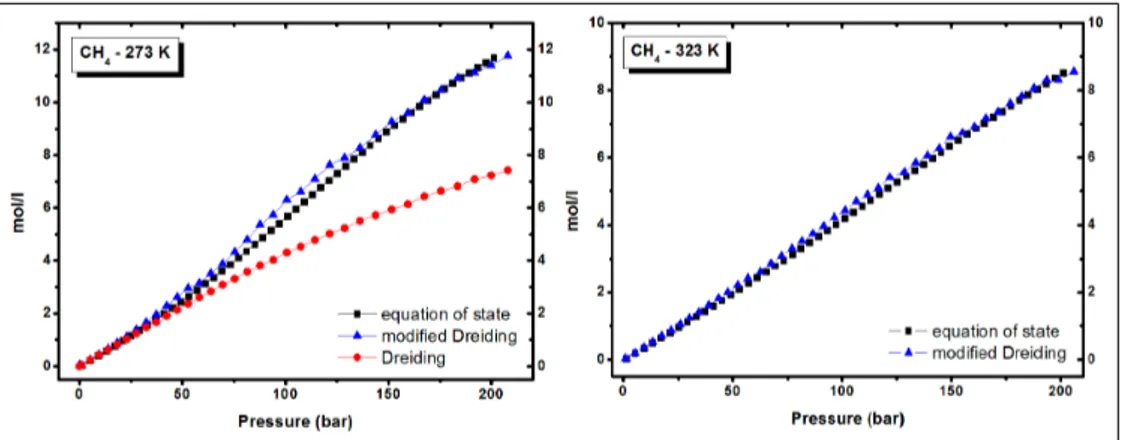
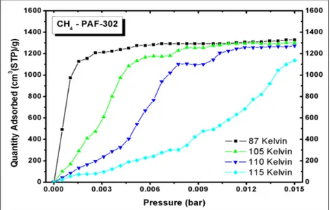
4.10.2 Methane . . . 57
4.10.3 FTIR, Raman and Theoretical Combined Study . . . 66
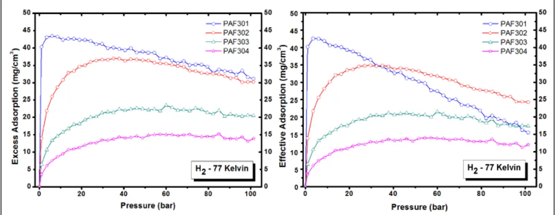
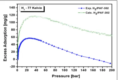
4.10.4 Hydrogen . . . 71
4.10.5 Carbon dioxide . . . 76
4.10.6 Functionalized PAF-302: CO2 adsorption . . . 82
4.11 Conclusion . . . 92
5 Computational details and results: mPAF 94 5.1 Introduction . . . 94
5.2 Synthesis and characterization: quick review . . . 95
5.3 Models Construction Scheme . . . 98
5.3.1 Define Monomer . . . 98
5.3.2 POLYMATIC, random polymeric procedure . . . 99
5.3.3 Amorphous periodic solid with Amorphous Cell . . . 100
5.4 Cross-linked Index and Crystalline Rate . . . 100
5.5 mPAF Structures . . . 102
5.5.1 Fully Hypercrosslinked Model (FHM) . . . 102
5.5.2 Random Branched Polymer(RBP) . . . 105
5.5.3 Random Core/Shell Polymer (RCSP) . . . 108
5.5.4 Random Hybrid Polymer (RHP) . . . 111
5.5.5 Random Hybrid Polymer with defective groups (RHP CH2OH) . . . . 114
5.6 Simulated Adsorption Isotherms in mPAF model . . . 118
5.7 Conclusion . . . 122
6 General Conclusion 124 Bibliografy 126 7 Appendix 141 7.0.1 Papers . . . 141
1 Gas Storage in Porous Polymers
1.1 Introduction
Porous materials have captured the worldwide attention, in these years.Interest, investments and efforts in scientific research and technological development around the world are rapidly increasing. These materials possess surface, structural, and bulk properties that make them relevant in various fields such as ion exchange, [1,2] adsorption (for separation), [3,4] catalysis [5, 6], and gas storage. [7–10]
In this introduction chapter the main storage systems for hydrogen, methane and carbon dioxide, as well as their porosity and surface area, will be described in relation to the main classes of porous materials that have been proposed for gas storage.
1.2 Gas storage
The growing world population and the increasing standard of living increase the concerns over the sustainability of oil reserves: the supply of economically usable hydrocarbon resources in the world is limited, and the demand for hydrocarbon fuels is increasing.
In the current hydrocarbon economy, transportation is fuelled primarily by petroleum. The burning of hydrocarbon fuels has an adverse effect on the environment as it is responsible for the increase in the earth’s atmosphere of CO2 and other pollutants.
A number of potential solutions for conservation and remediation of the environment due to CO2 increment are cutting edge research topics.
These include work in CO2 capture and storage, [11] as well as the use of cleaner fuels, such
as natural gas (CH4) [12] or hydrogen (H2). [13, 14]
1.2.1 H2 Capture
Hydrogen energy is one of the alternative energy candidates which are being considered as a replacement for fossil fuels. Hydrogen can be produced from a various sources including coals, natural gases, and ultimately water. It is non-toxic and environmentally clean energy as water would only remain after the cyclic usage of the energy.
The automobile industry, one of the main potential applications of hydrogen energy, requires stored hydrogen for mobile applications. Therefore, methods to store H2 with appropriate
weight and volume are important for successful applications.
The development of a hydrogen storage device having light weight and high capacity is a necessary condition to enable fuel cell vehicles to replace fossil fuel vehicles.
More importantly, the developed vehicle should be operated at temperatures of 323 - 423 Kelvin and pressures of 1 - 100 bar. The vehicle should also have a fast recharge/discharge cycle.
Unfortunately, molecular hydrogen that can be used as fuel does not occur naturally in convenient tanks.
methods. [15, 16]
Possible approaches for hydrogen storage include: [17]
• Physical storage of compressed hydrogen gas in high pressure tanks (up to 700 bar); • Physical storage of cryogenic hydrogen (cooled to -2530 C, at pressures of 6-350 bar) in
insulated tanks;
• Storage in advanced materials within the structure or on the surface of certain materials as well as in chemical compounds that can undergo a chemical reaction to release hydrogen.
Hydrogen has a very high energy content by weight (about three times higher than gasoline), but it has a very low energy content by volume (liquid hydrogen is about four times lower than gasoline). Currently, hydrogen is stored either in high pressure tanks or in liquid form in cryogenic tanks.
As far as the interaction/adsorption of hydrogen with/on a material is concerned, there are mainly three different approaches: [17]
• Physisorption: hydrogen remains molecular and binds weakly on the surface of the most common porous materials with a binding energy in the meV range. Hence, it desorbs already at very low temperatures. Sorbent materials belonging to this cate-gory are carbon-based materials such as nanotubes, fullerenes, graphene, mesoporous silica, metal-organic frameworks (MOFs), covalent organic frameworks (COFs), and clathrates. [19–21]
• Chemisorption: H2 molecule dissociates into individual atoms, migrates into the material, and binds chemically with a binding energy lying in the 2-4 eV range. As the bonding is strong, the desorption takes place at higher temperatures. Complex hydrides, which are light metal hydrides, are the main class of materials where hydrogen is held in strong covalent bonds. [22, 23]
• H2 weakened but not broken: The strength of interaction is intermediate
be-tween physisorption and chemisorption (binding energy in the 0.1-0.8 eV range). This type of adsorption concerns carbon-based nanostructured materials such as nanotubes, fullerenes and graphenes doped with metals and transition metals. [24–26]
Figure 1.1: Summary of various hydrogen storage materials and their limitations. [18]
Figure 1.1 summarizes the different types of materials being studied for hydrogen storage. [18] Metal hydrides are reversible under ambient conditions but are too heavy.
Simple chemical hydrides are reversible but only at very high pressure and temperature. Complex chemical hydrides have high hydrogen density but suffer from poor reversibility. Nanostructured materials are very promising but are yet to emerge as practical materials. In fact they offer good reversibility but require very low temperatures of storage. The kinetic of hydrogen adsorption by microporous materials is very rapid, which is a practical advantage for hydrogen storage, but low temperatures are required to achieve significant capacities at useful storage pressures.
In practice, low temperature storage requires cooling, which inevitably makes heavier the storage unit and is therefore a significant disadvantage. In order to achieve high volumetric capacities, adsorbed hydrogen must be stored at relatively high densities within the pores. For these reasons, the hydrogen adsorption capacity of microporous materials at ambient temperature is currently too low for practical use. [27] The actual research in this field is to enhance the interaction of hydrogen with the materials to reach an adsorption capacity sufficiently high for real applications.
1.2.2 CH4 Capture
Economical and environmental considerations have also boosted interest in Natural gas (NG) as a fuel for transportation, and especially as a replacement for petrol (gasoline).
In the generation of energy from methane, the major concern is the production of CO2,
though it is comparatively less than other fossil fuels (gasoline or diesel). Indeed, methane has a gravimetric heat of combustion (55.5 MJ/kg) comparable to that of gasoline (44.7 MJ/kg), but it boasts the smallest amount of CO2 per unit of heat produced among fossil
fuels, and it is naturally abundant. However, the lack of efficient storage methods has so far prevented the widespread use of NG in motor vehicles.
The two common methods of NG storage currently used are: • liquefaction at low temperature (down to 120 K) • compression to 200-300 bar at room temperature.
The volumetric energy density of Liquefied Natural Gas (LNG) is lower (22.2 MJ/l, 112 K) than that of gasoline (34.2 MJ/l) but requires the storage in expensive cryogenic vessels and it suffers from boil-off losses.
On the other hand, Compressed Natural Gas (CNG) necessitates the use of heavy, thick-walled cylindrical storage tanks and multi-stage compressors to achieve a reasonable volu-metric energy density, which is actually only 27% (9.2 MJ/l) with respect to gasoline. [28] Despite efforts to improve cylinders and compressors, the amount of NG stored in a CNG tank permits for only a short driving autonomy on light-duty passenger vehicles, and high pressure storage on vehicles has been associated to safety concerns. [29]
In order to take advantage of the benefits that the use of NG in vehicles may offer, attractive alternatives to CNG and LNG are needed. It has been suggested that porous adsorbents represent a safer, simpler, and potentially more cost-effective method for storing NG at am-bient temperature and reasonable pressures (around 35 bar) in the form of adsorbed NG (ANG). [30]
Similarly to hydrogen storage, also for CH4 the adsorption can be physical (weak van der
Waals forces) or chemical (significant covalent interactions) depending on the type and on the strength of the interaction between methane molecules and the material surface sites. From an application standpoint, the primary difference between physisorption and chemisorption is
the significant disparity in binding energies. For reversible gas storage and delivery, moderate binding energies (measured as heat of adsorption) are required to maximize energy efficiency of the system. Therefore, physisorptive materials are best suited for this application, as chemisorptive materials would require a substantial amount of external heat to release the adsorbed gas.
Figure 1.2: The increment of CH4 emissions during the period 1978-2006 [31]
To address the need for better technologies to combat the growing increase of emissions in the atmosphere CH4, in 1993, the U.S. Department of Energy (DOE) set the methane storage
target as 150 cm3 (STP)/ cm3 at 298 K and 35 bar. [32, 33]
As a result of efforts by a number of researchers, some MOFs exhibited considerably high methane uptakes, which exceeded the above DOE target. [34]
In 2012, the U.S. DOE initiated a Methane Opportunities for Vehicular Energy (MOVE) Program, and re-set several targets to guide the research on adsorbent-based methane storage [35]. The major target is that the adsorbent-level volumetric energy density should exceed 12.5 MJ/L and 9.2 MJ/L after packing losses (25%), at room temperature and low pressure (less than 35 bar). This corresponds to a volumetric storage capacity of 0.25 g/cm3 or 350 cm3 (STP)/ cm3 for the adsorbent material. Even assuming no packing loss, the volumetric storage capacity still needs to be higher than 260 cm3 (STP)/ cm3. [36] Clearly, this is an ambitious target, which none of the currently known adsorbent materials meet. In fact, even for the previously widelyreferred, much lower target of 150 cm3 (STP)/ cm3, there are only few materials known to reach this value. [37, 38] Additionally, DOE set a target concerning the gravimetric energy density, 0.5 g (methane)/g (adsorbent), or 700 cm3 (STP)/ g, which is equally challenging.
The ideal sorbent should also show resistance to impurities typically encountered in natural gas sources with a lifetime of at least 100 fillrelease cycles, and it should be cost effective approaching, $10/kg sorbent, in addition to other system level targets such as desorption rates, tank abuse tests, etc. [29]
About the storage measures, there are several volumetric measures used to quantify the fundamental characteristics of an underground storage facility and the gas contained within it.
facility such as its capacity, and the characteristic of the gas within the facility such as the actual inventory level. These measures are as follows:
• Total gas storage capacity is the maximum volume of gas that can be stored in an underground storage facility in accordance with its design, which comprises the physical characteristics of the reservoir, installed equipment, and operating procedures particular to the site.
• Total gas in storage is the volume of storage in the underground facility at a particular time.
• Base gas (or cushion gas) is the volume of gas intended as permanent inventory in a storage reservoir to maintain adequate pressure and deliverability rates throughout the withdrawal season.
• Working gas capacity refers to total gas storage capacity minus base gas.
• Working gas is the volume of gas in the reservoir above the level of base gas. Working gas is available to the marketplace.
• Deliverability is most often expressed as a measure of the amount of gas that can be delivered (withdrawn) from a storage facility on a daily basis. Also referred to as the deliverability rate, withdrawal rate, or withdrawal capacity, deliverability is usually expressed in terms of millions of cubic feet per day (MMcf/day). Occasionally, deliverability is expressed in terms of equivalent heat content of the gas withdrawn from the facility, most often in dekatherms per day (a therm is 100,000 Btu, which is roughly equivalent to 100 cubic feet of natural gas; a dekatherm is the equivalent of about one thousand cubic feet (Mcf)). The deliverability of a given storage facility is variable, and depends on factors such as the amount of gas in the reservoir at any particular time, the pressure within the reservoir, compression capability available to the reservoir, the configuration and capabilities of surface facilities associated with the reservoir, and other factors. In general, a facility’s deliverability rate varies directly with the total amount of gas in the reservoir: it is at its highest when the reservoir is most full and declines as working gas is withdrawn.
• Injection capacity (or rate) is the complement of the deliverability or withdrawal rate-it is the amount of gas that can be injected into a storage facility on a daily basis. As with deliverability, injection capacity is usually expressed in MMcf/day, although dekatherms/day is also used. The injection capacity of a storage facility is also variable, and is dependent on factors comparable to those that determine deliverability. By contrast, the injection rate varies inversely with the total amount of gas in storage: it is at its lowest when the reservoir is most full and increases as working gas is withdrawn.
1.2.3 CO2 Capture and Storage (CCS)
Beside the development of technologies for the use of methane [39] and hydrogen [40] as clean fuels, industrial technologies for carbon dioxide capture are vital in environmental safety. Due to growing levels of greenhouse gas emissions (Figure 1.3), separation of CO2 from
mixtures of gases such as the gas emitted from the combustion of fossil fuels is of great im-portance. [41]
Figure 1.3: The increment of CO2 concentration during the period 1965-2010 (at
Mauna Loa Observatory), in the atmosphere. [42]
Carbon capture and storage (CCS) is an efficient way to reduce CO2 concentration in the
atmosphere. It is a three-step process including separation of CO2 from other gases before
reaching the atmosphere, CO2 transportation, and its permanent storage. [42] Among them,
the CO2 capture is the most challenging key step for which new adsorbent materials need to
be developed. Conventional adsorbent materials rely on either chemisorption or physisorption to capture CO2.
There are three major approaches for CCS: pre-combustion capture, oxy-fuel process and post-combustion capture: [43]
• In pre-combustion, the fossil fuel is partially oxidized in a gasifier. The resulting syngas (CO and H2) is shifted into H2 and CO2, which can be captured from the stream.
• Oxy-combustion occurs when the fuel is burned in the presence of oxygen. The resulting flow gas consists mainly of pure CO2 which can be transported to the sequestration site
and stored.
• The post combustion capture is based on removing CO2from the flow gas after
combus-tion. Instead of being released directly into the atmosphere, flue gas is passed through a particular equipment that separates/captures most of the CO2.
Post-combustion capture offers some advantages since existing combustion technologies can still be employed without radical changes. This makes post-combustion capture easier to implement as a retrofit option compared to the other two approaches.
Various technologies such as membrane separation, cryogenic distillation and adsorption can be used for CO2 capture. The adsorption is the ideal way to achieve efficient CCS. It is
a separation technology, able to reduce both cost and energy of post-combustion capture compared to other technologies. Selective capture and subsequent storage of carbon dioxide in porous materials has been considered as a promising new approach. [11]
The adsorbents used for CO2capture can be placed into two categories: physical and chemical
adsorbents. [44]
• Chemisorption is a sub-class of adsorption, driven by a chemical reaction occurring at the exposed surface. Chemical adsorbents are mostly metal compounds such as metal oxides and metal salts.
• Physisorption is a process in which the electronic structure of the atom or molecule is barely perturbed upon adsorption. The major physical adsorbents reported for CO2
adsorption include activated carbons and inorganic porous materials such as zeolites. However, the success of this approach is dependent on the development of adsorbents with high capacity and selectivity; Ideally, this has to be environmentally benign, renewable, safe, and cost-effective. [42]
In summary, the goal remains in the development of low-cost and high-performance adsor-bents for CO2 sequestration, gas separation and energy storage applications.
1.2.4 Nitrogen and Argon Storage
Pore size analysis of mesoporous materials from adsorption isotherms is based on an adopted interpretation of the mechanisms of capillary condensation and evaporation and associated hysteresis phenomena. [45, 52]
Nitrogen is the probe gas most commonly used for pore size distributions (PSD) analysis be-cause it is inexpensive, readily obtained, inert, and well-studied in the adsorption literature. The experimental isotherm is usually measured at the normal liquid nitrogen boiling point of 77 K, which is sufficiently below the critical temperature so that a large uptake of the ad-sorbate is realized. This is again a convenient choice, since liquid nitrogen is inexpensive and isothermal conditions can easily be maintained using liquid nitrogen as a cryostat. Despite these merits, there may arise situations in which a probe gas species other than nitrogen is desirable. On activated carbons that have substantial chemical heterogeneity, there may be significant interactions between the quadrupolar nitrogen molecule and various functional groups on the carbon surface.
Argon is an ideal probe gas for characterizing the pore structure of heterogeneous adsorbents, since it is a monatomic, spherical molecule with no multipolar moments and it is similar in size to nitrogen. Argon porosimetry has been used extensively for PSD analysis of activated carbons, silicas, aluminas, and mesoporous oxides. [139,140] DFT model isotherms have been computed for argon adsorption at its normal boiling point of 87 K.
This temperature is readily maintained by using liquid argon as the temperature bath for the sorption measurement.
Because liquid argon is more expensive than liquid nitrogen, however, it is convenient and economical to carry out the argon adsorption measurement at the normal liquid nitrogen boiling point of 77 K.
1.3 Adsorption Isotherms and Porosity
The adsorption of guest molecules into a solid surface plays an essential role in determining the properties of porous compounds. Depending upon the strength of the interaction, all adsorption processes can be divided into chemical and physical adsorption categories.
• Chemical adsorption or chemisorption involves valence forces of the same type as those operating in the formation of chemical compounds.
• Physical adsorption or physisorption is a general phenomenon which occurs when-ever a gas (the adsorbate) is brought into contact with the surface of a solid (the ad-sorbent), in this case the forces involved are intermolecular forces (van der Waals) and always include the long-range London dispersion forces and the short-range intermolec-ular repulsion. [45]
Adsorption is described through isotherms, which correlate the amount of gas adsorbed to the pressure in the system at a constant temperature. The adsorbed gas quantity is always normalized to the mass of adsorbent to allow the comparison with other materials.
The textural analysis of powders is usually performed by physisorption of nitrogen, argon and krypton at cryogenic temperatures (77 K and 87 K). From a proper isotherm, it is possible to extract information about surface area, pore size and porosity of a given material.
IUPAC proposed to classify pores by their internal pore width: • Macropores ≥ 50 nm widths;
• Mesopoeres Pores between 2 and 50 nm widths; • Micropores Pores ≤ 2 nm widths;
– Supermicropores between 0.7 and 2 nm; – Ultramicropores ≤ 0.7 nm;
The sorption behaviour in mesopores is distinct from the adsorption phenomena occurring in micropores. The mesopore adsorption is dominated by capillary condensation, which is responsible for a sharp adsorption enhancement around the mid relative-pressure region. Conversely the adsorption in a micropore should not be considered as that of molecules onto a solid surface but as the filling of molecules into a nanospace where a deep potential field is generated between the adsorbate molecules and the pore walls. In this case, the adsorption isotherm shows a steep rise at very low relative pressure and a plateau after saturation. [46] Based on IUPAC classification, there are six representative adsorption isotherms that reflect the relationship between porous structure and type of sorption (Figure 1.4a). [47]
Figure 1.4: (a) Types of physisorption isotherms; (b) Types of hysteresis loops .
These adsorption isotherms are characteristics of microporous (Type I), nonporous and macroporous (types II, III and VI), and mesoporous (type IV and V) adsorbents.
An empirical classification of hysteresis loops was given by IUPAC (Figure 1.4b), in which the shape of the hysteresis loops (types H1 - H4) is correlated to the adsorbent texture. According to this classification: [47, 48]
• Type H1 is often associated with porous materials exhibiting a narrow distribution of relatively uniform (cylindrical-like) pores.
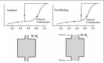
• Materials that give rise to H2 hysteresis contain a more complex pore structure in which network effects such as pore blocking percolation and cavitation are relevant (Figure 1.5). [49–51] In case of pore blocking (sometimes called ink-bottle) desorption from the
pore body may occur only after emptying its neck. In other words, desorption from the neck triggers evaporation in the blocked pore. Thus, the vapour pressure of desorption from the pore body depends on neck size, network connectivity, and on the state of the neighbouring pores. While the mechanism of desorption involves cavitation phenomena (spontaneous nucleation and growth of gas bubbles in the metastable condensed fluid) when the neck diameter is smaller than a certain critical width (estimated to be ca. 6 nm for nitrogen at 77.4 K). In this case, the pore body empties while the pore neck remains filled.
• Isotherms with type H3 hysteresis do not exhibit any limiting adsorption at high P/P0.
This behaviour can be caused by the existence of non-rigid aggregates and in prin-ciple should not be expected to provide a reliable assessment of either the pore size distribution or the total pore volume.
• H4 hysteresis loops are generally observed with complex materials containing both micropores and mesopores.
Figure 1.5: Schematic illustration of pore blocking and cavitation controlled evaporation. [48]
Great progress was achieved in the understanding of adsorption, capillary condensation, and desorption phenomena in highly ordered mesoporous materials with simple pore geometries, such as MCM and SBA-type mesoporous silica crystals. [52]
However, there are still many open questions concerning adsorption-desorption mechanisms in more complex porous systems. Fluids adsorbed in hierarchically structured micromeso-porous materials exhibit a great variety of hysteretic adsorption-desorption isotherms with multiple steps related to phase transformations in adsorbed phases.
Adsorption-desorption processes involve a combination of physical mechanisms, such as de-layed condensation, advanced condensation, cavitation-induced evaporation, pore blocking, and percolation, which are reflected in characteristic types of hysteresis loops formed by ad-sorption and dead-sorption isotherms. [53]
The hysteresis loop causes a considerable complication for the pore structure characteriza-tion; however, if interpreted correctly, hysteresis loops can provide important information on pore network morphology, which is crucial for discriminating the physical mechanisms of phase transformation. [54]
1.4 Surface Area
The surface area is one of the most important factors for evaluating the adsorption capacity of porous materials. Adsorbents have a high effective surface area exposed, per gram of material, expressed in m2/g. The specific surface area (SSA) is a relevant textural parameter of adsorbent materials.
Conventionally, the Brunauer-Emmett-Teller (BET) gas adsorption method has become the most widely used standard procedure for the determination of the SSA, in spite of the over simplification of the theoretical model on which is based. [45]
In particular, the BET model applied to the N2 adsorption data at 77 K has been widely
used to characterize the adsorbent material of interest. It assumes that once a monolayer becomes saturated, a further monolayer can form on top, and that the rates of adsorption and desorption are equal for each layer.
There are several methods to calculate the surface area of computational models. In this work we have taken into account mainly two methodologies: the Van der Waals surfaces and the Connolly surfaces.
. Figure 1.6: (a) Van der Waals surface and (b) Connolly surface. .
The van der Waals surface of a molecule corresponds to the outer surfaces of the radii of van der Waals forces of the atoms. The molecular surface is generated by rolling a spherical ”probe” (generally with a radius of 1.4 to represent a molecule of water) on the surface by van der Waals forces. The molecular surface is the contact surface. The accessible surface to the solvent (or Connolly) is instead drawn from the center of the probe in the same manner.
1.5 Adsorbent properties for best performance gas storage
The work of this thesis primarily concerns with the study of physical adsorption in different porous materials. Each gas and its associated applications have criteria that should be met for any gas storage material to be of use in practice.
In general, there are different sets of performance criteria for a good adsorbent as listed below: [57]
• High adsorption capacity. One of the most important parameters is the high specific surface area (SSA). However, simple considerations based on SSA are not enough to obtain an efficient material: also the sizes of the pores are of considerable importance, as adsorption predominantly occurs within the pores that are able to create a sufficiently
high attractive potential. Such a situation is met as soon as the pore walls are so close to each other that their own potential fields overlap. This affects the bonding strength of the molecules to the adsorbent surface, which is related to the isosteric heat of adsorption. [58] Thus, the most relevant properties that affect the gas adsorption capacity are SSA, surface chemical nature, and pore size. These parameters determine how much adsorbates can be accumulated per unit mass of adsorbents.
• High selectivity. For multicomponent mixtures, selectivity is highly desirable for gas separation. The selectivity of an adsorbent will depend on pore size, shape and pore size distribution as well as on the nature of the adsorbate components.
• Favorable adsorption kinetics. Adsorption kinetics is determined by the particle (crys-tallite) size, and by the macro-, meso and microporosity of the adsorbent. Sometimes, binder type and amount would also affect the interparticle transport and thus the global adsorption process kinetics. For a favourable kinetic, the adsorption rate should be high or controllable depending on the requirements of a particular application.
• Excellent mechanical properties. Adsorbents need to be mechanically strong and robust enough to stand attrition, erosion and crushing in adsorption columns or vessels. High bulk density and crushing strength, and attrition resistance are desirable.
• Good stability and durability in use. Adsorbents are often subject to harsh chemical environments or to high pressure and thermal conditions. A high stability in those environments/conditions is essential in ensuring long life or durable utilization.
Obviously, the practical challenges concern the preparation of high performance materials in a simple and cost effective manner and the materials should meet the above require-ments/criteria as much as possible.
2 Porous materials for gas storage
2.1 Introduction
In recent years, nanoporous materials have been a core focus of scientific and technological importance because of their ability to adsorb atoms, ions and molecules.
The main classes of materials that show good performances for gas storage are: [59–66] 1. Porous Carbons
2. Porous Inorganic Materials
3. Metal Organic Framework materials (MOFs) 4. Microporous organic polymers
• Polymers of intrinsic microporosity (PIMs) • Covalent organic frameworks (COFs) • Conjugated microporous polymers (CMPs) • HyperCrosslinked polymers (HCPs)
• Porous aromatic frameworks (PAFs)
- microPorous Aromatic Frameworks (mPAF)
2.2 Porous Carbons
Several types of porous carbons such as activated carbons, carbon nanotubes and nanofibers and microporous templated carbons have attracted interest for gas storage. [80] From a prac-tical point of view, porous carbons are already commercially produced in large quantities for a broad range of applications and are relatively inexpensive. Among porous carbons, activated carbons are the most widely studied family. They are a form of carbon processed to have small, low-volume pores that increase the surface area available for adsorption or chemical reactions. [60] Activated is sometimes substituted with active.
Activated carbon is used in gas purification, [82–85] decaffeination, gold purification, metal extraction, [86] water purification, [88] medicine, sewage treatment, air filters in gas masks and respirators, filters in compressed air and many other applications. [89] One major indus-trial application involves use of activated carbon in the metal finishing field.
They are also very widely employed for purification of electroplating solutions, for example, for removing organic impurities from bright nickel plating solutions. A variety of organic chemicals are added to plating solutions for improving their deposit qualities and for enhanc-ing properties like brightness, smoothness, ductility, etc. Due to passage of direct current and electrolytic reactions of anodic oxidation and cathodic reduction, organic additives generate unwanted breakdown products in solution. Their excessive build up can adversely affect the plating quality and physical properties of deposited metal. Activated carbon treatment re-moves such impurities and restores plating performance to the desired level. [62]
in excess of 500 m2, as determined by gas adsorption. [61] An activation level sufficient for useful application may be attained solely from high surface area; however, further chemical treatment often enhances adsorption properties.
These materials generally are prepared from a carbonaceous starting materials (coal, wood, coconut husks . etc) by a thermal treatment or chemical treatment, which can lead to poly-meric systems with large surface areas, often well in excess of 1000 m2/g and even up to > 3000 m2/g. [81]
.
Figure 2.1: Rapresentation of the pore structure of activated carbons .
Unfortunately, due to their method of production, most activated carbons have a wide distri-bution of pores sizes ranging from microporous to macroporous. Additionally, the surface of activated carbons is chemically well defined with a mixture of oxygen and nitrogen functional groups. These two factors combine to give an excellent adsorbent material for a wide range of species, though it suffers from poor selectivity for specific molecules. Moreover, improvement of the storage capacity for porous carbons is currently limited by the difficulties in increasing the surface area above 3500 m2/g, being this parameter strongly correlated with the amount of gas that can be stored in the material.
2.3 Porous Inorganic Materials
Porous inorganic materials cover a range of solids, both oxides and nonoxides, crystalline and amorphous, that have a pore size extending from about 3 ˚A to over 500 ˚A. The main materials of this family are zeolites. Zeolites are hydrated aluminosilicate minerals made from interlinked tetrahedra of alumina (AlO4) and silica (SiO4).
They are solids with a relatively open, three-dimensional crystal structure built from the el-ements aluminum, oxygen, and silicon, with alkali or alkaline-Earth metals (such as sodium,
potassium, and magnesium) plus water molecules trapped in the gaps between them. Zeolites form with many different crystalline structures, which have large open pores (some-times referred to as cavities) in a very regular arrangement and roughly the same size as small molecules.
There are about 40 naturally occurring zeolites, forming in both volcanic and sedimentary rocks; according to the US Geological Survey, the most commonly mined forms include chabazite, clinoptilolite, and mordenite.
Dozens more artificial, synthetic zeolites (around 150) have been designed for specific pur-poses, the best known of which are zeolite A (commonly used as a laundry detergent), [67,68] zeolites X and Y (two different types of faujasites, used for catalytic cracking) [69, 70] and the petroleum catalyst ZSM-5 (a branded name for pentasil-zeolite). [71]
. Figure 2.2: ZSM-5: (a) the pentasil unit; (b) chains of pentasil units; (c) layers
of these chains; and (d) layers linked across inversion centres. [71] .
Zeolites have a number of significant practical advantages over other microporous adsorbents in that, for example, they possess high thermal stability. [72, 73]
However, it seems unlikely that zeolites could be useful as practical gas storage media as discussed by Felderhoff et al.. [74]
The problems encountered when using zeolites as adsorbents for the storage of gas are the following: [75, 76]
• The presence of non-structural porosity given by aggregations of zeolite particles, which diminish the amount of material in the same volume and thus worsen the gas storage. • Zeolites with hydrophilic character may preferentially adsorb traces of water found in
gas mixtures, with a consequent reduction in storage capacity. • Relatively low surface areas (<1000 m2/g).
2.4 Metal-Organic Frameworks (MOFs)
In recent years, a new class of crystalline materials called MOFs (Metal Organic Frame-works) has been synthesized and characterized by the presence of organic functionality and adjustable pore size and porosity, all features that make them attractive for use in gas stor-age. [77]
In some cases, the pores are stable for the removal of the guest molecules (often solvents) and can be used for storage of hydrogen and carbon dioxide. [90, 91]
The synthesis is based on the principles of reticular chemistry, which allows the design and structure prediction. The final product using the constituent unit secondary (Secondary Building Unit, SBU) allows to obtain stable materials transforming these individual frag-ments in a porous lattice extended. [92]
The SBUs are clustered inorganic and / or molecular complexes formed after the coordination of ligands to metal ions by organic linkers to obtain structures, much more extensive, both bidimensional and tridimensional. [87]
The SBU are crosslinked to form the metal-organic structure through the connection of the points of extensions present in each SBU using organic binders.
The choice of the organic binder is of fundamental importance since it determines the struc-ture of the lattice, the size of the pores and the surface area of the material. To induce porosity permanent structures rigid ligands are usually chosen, for which among all the pos-sible systems, aromatic ones are preferred with respect to alkyl chains characterized by high flexibility.
In figure 2.3 an example of isostructural MOFs has shown, which has the same SBUs but different organic binders.
.
Figure 2.3: Examples of MOFs iso reticular called IRMOS synthesized by Petit et al. [78] Atoms Zinc (blue polyhedra), oxygen atoms (red spheres), carbon atoms (black spheres). The yellow spheres represent the diameter of the pores. .
The MOFs, thanks to their porosity and high surface area, can be used in various applications, in particular, have been much studied in the last decade for their storage capacity of CH4,
H2, CO2. [79, 93]
However, these materials are generally less robust than zeolites and microporous carbons, because they exhibit lower thermal and chemical stability that hinder them from usage under extreme conditions.
Nevertheless, their commercialization is already under way, principally by BASF who markets a series of framework materials under the trade name Basolite TM, and so the practical application and use of these materials on an industrial scale is clearly feasible.
2.5 Microporous organic polymers
Porous Organic Polymers is another class of microporous materials of great interest in lit-erature. They can be divided in several subclasses of polymers, which have in common the following features: [96]
• The structure is formed by light elements (H, B, C, O and Si) that are linked by strong covalent bonds (B-O, C-O, C-C, B-C, and Si-C).
• A high thermal and chemical stability to air and atmospheric moisture since they are linked by strong covalent bonds.
• Normally, they do not have a long range order. Thus, their structure is amorphous due to irreversible bond formation governed by a kinetic control.
• They can be constructed using a plethora of organic reactions and building blocks, which provides flexibility for the material design to achieve desirable pore properties. In all the materials is possible to use a wide range of organic functionalities using different synthetic strategies and a great choice of monomers that makes it easy to introduce various functional groups in the pore walls. [97]
• They show high specific surface area and microporosity, two properties of fundamen-tal importance in gas storage. At the moment, they are the reference point for the evaluation of the capacity of an adsorbent material.
The main classes of microporous organic polymer that are considered as potential candi-dates for gas storage are: Polymers of Intrinsic Microporosity (PIMs), Covalent Organic Frameworks (COFs), conjugated Microporous Polymers (CMPs), Hypercrosslinked Polymers (HCPs) and Porous Aromatic Frameworks (PAFs). [98]
2.5.1 Polymers of Intrinsic Microporosity (PIMs)
Polymers of intrinsic microporosity (PIMs) are a group of polymeric materials which don’t require a network of covalent bonds in order to show microporosity; indeed intrinsic microp-orosity in polymers is defined as a continuous network of interconnected intermolecular voids, which are formed as a direct consequence of the shape and rigidity of the component macro-molecules. [99]
PIMs are amorphous solids due to their random packing and lack of long-range order, but possess surface areas in the range of 400 - 1760 m2/g. [100] Usually they are formed by a dou-ble nucleophilic aromatic substitution reaction between a tetrahydroxylated monomer and a tetrafluorinated monomer, resulting in the formation of dioxane links between monomer units (Figure 2.4).
It is essential for the production of a microporous PIM that one of the monomers has a highly rigid and contort structure.
. Figure 2.4: Typical molecular models of PIM polymer. [59]
Hydrogen uptakes of up to 2.7 wt%, at 10 bar and 77 K, have been reported for a triptycene-based polymer (trip-PIM). [101]
2.5.2 Covalent Organic Frameworks (COFs)
Covalent organic frameworks (COFs) are a class of crystalline porous polymers with precisely integrated organic units to create predesigned skeletons and nanopores. [105]
Being composed of light-weight elements linked by strong covalent bonds, COFs have low mass densities, possess high thermal stabilities, and provide permanent porosity. [104] Depending on the building block dimensions, COFs can be categorized into either two-(2D) [102] or three-dimensional (3D) COFs. [103]
In 2D COFs, the covalently bound framework is restricted to 2D sheets, which stack to form a layered eclipsed structure that presents periodically aligned columns. [106] This columnar stacking structure provides a unique mean to construct ordered p systems that are difficult to create via conventional covalent and/or noncovalent approaches. The ordered columns in 2D COFs could facilitate charge carrier transport in the stacking direction, which implies that 2D COFs have potential for developing new type p-electronic and photofunctional materials for optoelectronics and photovoltaics.
In contrast, 3D COFs, formed by building blocks containing an sp3 carbon or silane atom,
characteristically possess high specific surface areas (in some cases larger than 4000 m2/g),
numerous open sites, and low densities, as low as 0.17 g/cm3. The group of Farha et al. synthesized COFS with other 2D and 3D framework, [95] characterized by high surface areas (COF-102 (Fig.2.5a) and COF-103 (3472 and 4210 m2/g, respectively) and very low density
as for example, the COF-108 (Fig.2.5c) with a value 0.17 g/cm3, which is currently the lowest value ever achieved by a porous crystalline material.
. Figure 2.5: 3D Structures of (a)COF-102, (b)COF-103 and (c)COF-108. [94]
The storage capabilities of COFs for gases, such as hydrogen, methane, and carbon dioxide, have been widely investigated. [107–109]
2.5.3 Conjugated Microporous Polymers (CMPs)
Conjugated microporous polymers (CMPs) are a class of porous materials with amorphous three-dimensional organic framework made up of multiple carboncarbon bonds and/or aro-matic rings that form an extended conjugated network.
CMPs were first reported in 2007 [110] and took advantage of Sonogashira-Hagihara palla-dium coupling to link aromatic halides to aromatic alkynes, thus forming poly(aryleneethynylene) (PAE) networks, with BET surface areas that exceed 1000 m2/g in some cases. [111, 112] CMPs are formed under kinetic control and display no long-range order, but their pore sizes are well-defined and can be controlled by careful selection of the monomers. [101] Surface areas can also be controlled by changing the linker length, with the number of micropores decreasing with increasing linker length. This behavior can be explained by the extra flex-ibility granted to the framework by longer linkers, that allow a more efficient packing and decrease the available surface area. [113]
Thanks to the study on PAEs it was discovered that:
• similarly to the crystalline materials, such as MOFs and COFS, the surface area and pore distribution can be modulated according to the type of organic linker that connects the monomers
• the structural order is not a prerequisite for controlling of microporosity.
. Figure 2.6: Cyano cyclotrimerization reactions occur under ionothermal
The research performed on CMPs has focused on broadening the range of functional groups that can be incorporated into the frameworks, with the aim to tune the properties of the materials for different applications.
CMPs are currently attracting considerable interest as materials that combine the mechanical stability of polymers with adjustable optoelectronic properties of organic molecules. In fact, species belonging to the family of conjugated polymers have already been exploited for some applications like optoelectronic OLED (Organic Light Emission Diode) for photovoltaic cells and FET transistor. [115, 116]
2.5.4 HyperCrosslinked Polymers (HCPs)
HCPs represent a class of low cost porous materials, which can be prepared mainly by the Friedel-Crafts alkylation reaction. The permanent porosity in HCPs is a result of extensive crosslinking reactions, which prevents the polymer chains from collapsing into a dense, non-porous state. [117]
The crosslinking produces a highly rigid network structure with high thermal stability that is not commonly expected for organic polymers. Combined with their light weight proper-ties, small pore size, micropore volume and high surface areas, HCPs can be considered as promising materials for H2 and CO2 storage applications. [118, 119]
According to the synthetic method, HCPs can be produced by the following procedures: [120] 1. intermolecular and intramolecular cross-linking of preformed polymer chains (either
linear chains or lightly cross-linked gels).
2. self-condensation of chloromethyl- or hydroxymethylaromatics in the presence of FeCl3.
3. knitting aromatic compounds using cross-linking agents.
. Figure 2.7: Schematic representation of the Hypercrosslinking process, reaction
scheme for the synthesis of a HCP polymer prepared from gel
poly(divinylbenzene-co-vinylbenzyl chloride) [120] and the final polymer scheme. In the literature there are many examples of synthesis of HCP. Davankov-type resins are the first type of hypercrosslinked materials, which have been well-studied and are pre-pared by post-crosslinking of linear polystyrene (PS), poly(vinylbenzyl chloride), or their
pre-crosslinked copolymers with a divinylbenzene (DVB) moiety. [117]
Direct step growth polycondensation of suitable monomers: this is an approach to microp-orous organic networks that uses bis(chloromethyl) aromatic monomers such as dichloroxylene (DCX), bis(chloromethyl)biphenyl (BCMBP), and bis(chloromethyl) anthracene. [112] The HCP polymers obtained using these precursors are predominantly microporous and ex-hibit apparent BET surface areas of up to 1904 m2/g as measured by nitrogen adsorption at 77 K. [121]
Knitting aromatic compound polymers (KAPs) using an external crosslinking agent.
This procedure has been recently developed and consists in the simple one-step Friedel-Crafts reaction between an aromatic monomer and formaldehyde dimethyl acetal (FDA): in the pres-ence of FeCl3 as catalyst various aromatic monomers can be directly crosslinked to form the
highly porous networks (Figure 2.8). [123]
. Figure 2.8: Scheme showing the synthetic pathway of HCP polymers using an
external crosslinking agent [123].
Also Cooper group demonstrated that this knitting approach can produce networks with sur-face area of up to 1470 m2/g when using the tetrahedral monomer, tetraphenylmethane. [124] This method avoids the need for monomers with specific polymerizable groups and also avoids the use of precious metal coupling catalysts.
Various functional groups can also be easily introduced into the porous frameworks just by choosing the proper monomers.
Based on the combination of large specific surface area and enhanced microporosity, HCPs show good potential for gas storage. [126–129]
The properties of HCPs can be fine-tuned for a specific purpose by post synthetic modifica-tion. [122]
This is possible because the hypercross-linking reaction doesn’t occur at each possible site, resulting in residual chloromethyl groups being present in the polymeric matrix.
Thus, functional groups, such as amines or alcohols, can be transferred to the polymer matrix by replacing these residual chlorine atoms.
This enables to improve the storage capacity of these materials and extends their application as adsorbents for toxic organic [130] and inorganic contaminants. [4]
2.5.5 Porous Aromatic Frameworks (PAFs)
Porous aromatic frameworks (PAFs) are a family of microporous polyphenylic networks char-acterized by a three-dimensional, rigid and open-network structures.
The original idea for the synthesis of PAF came from the structure and properties of diamond, in which each carbon atom is tetrahedrally connected to four neighboring atoms by covalent bonds.
Breaking the C-C covalent bond of diamond and inserting rigid phenyl rings allow sufficient exposure of the faces and edges of phenyl rings with the expectation of increasing the internal surface areas.
Ben et al. [21] have proposed, indicating the structure and some of the main characteris-tics related to the porosity and the hydrogen storage capacity, obtained by the Monte Carlo method, the structures of other materials belonging to the class of PAFs: PAF-301 with one aromatic ring, PAF-303 with three aromatic rings interspersed in CC bond and the PAF-304 with four aromatic rings (Figura 2.9).
. Figure 2.9: Unit cells of PAFs, (a) PAF-301, (b) PAF-302, (c) PAF-303, and (d)
PAF-304, derived from topology design and geometry optimization with the force field method. Here, gray and pink spheres represent carbon and hydrogen
atoms, respectively, while the blue polyhedron represents the tetrahedrally bonded carbon atoms. In addition, the yellow sphere denotes the pores in 3D
PAFs. [21]
The previuos year, in 2009, the same group [131, 132] developed a method to synthesize the first long range ordered porous aromatic framework (PAF) with diamond-like topology (PAF-1 or PAF-302), which had a record surface area (SBET = 5640 m2/g) at that time and exceptional physicochemical stability via a nickel(0)-catalyzed Yamamoto-type cross-coupling reaction (Figure 2.10).
. Figure 2.10: Synthesis scheme of the PAF-1 using Yamamoto coupling reaction For a long time it was thought that the low surface area of porous organic polymers was due to the amorphous structure, but thanks to PAF-1, it has been shown that even non-crystalline materials could reach very high surface areas.
This exceptional surface area, according to Hong-Cai Zhou, [133] is mainly due to three factors:
- The highly efficient Yamamoto reaction helps to eliminate unreacted terms at the monomers and therefore highly connected frameworks are formed. [134]
- The default diamond framework topology, imposed by the tetrahedral monomers, pro-vides widely open and interconnected pores to efficiently prevent the formation of dead space.
- The prevailing robust covalent C-C bond connecting the whole framework leads to a material with exceptionally high thermal and chemical stability.
Compared with other ultrahigh surface area solids such as porous carbons, porous silicas, zeo-lites, MOF and microporous polymers, PAFs show very high thermal (>450oC) and excellent
physicochemical stabilities.They are also characterized by excellent adsorption abilities for CO2, H2 and CH4. [135, 136]
Yamamoto reaction is advantageous as only one type of functionality is required and just a single, halogenfunctionalized monomer can be used to form high molecular weight polyaro-matics frameworks.
Compared with other C-C coupling reactions in literature, Yamamoto coupling shows the unexpected ability to eliminate terminal halogen atoms. This makes the reaction unique to prepare ultrahigh porous solids because heavy ending halogen atoms lead to solids with low surface area. [137]
On the other hand, stoichiometric (or excess) quantities of the nickel complex are required because the catalyst is very sensitive. [138]
However, this catalyst is very expansive and toxic.
For these reasons, our experimental group studied the “in situ” preparation of the cata-lyst and has concerned another type of optimization for the material PAF-302, the use of microwave irradiation as an alternative route to heat source. This technique generally has several advantages including the very fast and homogeneous heating that can result in the reduction of side reactions, cleaner products, and higher yields.
Besides these new preparation appproaches, the optimization of the experimental conditions for the synthesis of PAF-302 in order to obtain reproducible high surface area materials, as well as the reduction of the costs of the synthesis, has been paid to the improvement of the
storage capacity.
A comparative investigation of the physico-chemical properties of the synthesized materials was carried out by a multidisciplinary approach using infrared (IR) and Solid State Nuclear Magnetic Resonance (SS-NMR) spectroscopy and powder X-ray diffraction (PXRD) to eval-uate the structural characteristics of the materials and finally Thermal gravimetric analysis (TGA) was used to study the thermal stability of the polymers.
However, the key parameters adopted to demonstrate the success of the synthesized materials are the pore diameter distribution, the pore volume and the surface area measured by N2
physisorption at 77 K.
In the chapter 4 theoretical calculations concerning the FTIR spectra, pore distributions and capacity storage of gases will be presented and they will be compared to help the interpreta-tion of both spectroscopic and adsorpinterpreta-tion isotherm results.
The capacity storage of CH4, H2 and CO2 for best materials will be evaluated simulating the
adsorption properties of PAF-30n (n = 1-4) at various temperatures, to find the most suitable materials. The theoretical study of these materials has focused, initially, on the optimization of the constituent units of the four PAF and, in particular, on the distance of the C-C bond between the tetrahedral carbon and the carbon of the aromatic ring. Later, the structures of the different PAFs were built with the new coordinates of the cell and they were analyzed two types of interactions:
- Adsorbate-adsorbate interactions - Adsorbent-adsorbate interactions
The latter refer to the interactions that occur between the gas molecules taken into account and parts of the structure of the PAF, the former, however, are created between the individual molecules of gas, which, tending to repel each other.
The adsorpion was studied ay differnt pressures using the Monte-Carlo method based on the principle of the force fields, to understand the amount of gas that can be stored in each of the four PAF30n considered.
Therefore, the CO2 adsorption then was simulated in a number of modified PAF-302, with
different functional groups (aminomethane, toluene, pyridine, and imidazole) attached to the phenyl chains; different degrees of substitution (25%, 50%, and 100% derivatized rings) were considered. The effects of functionalization and the dependence on the substitution degree are discussed, to determine the most promising materials at low, intermediate, and high pressures.
2.5.6 microPorous Aromatic Frameworks (mPAF)
Recently, a new method for preparing microporous polymers by using formaldehyde dimethyl acetal (FDA) as cross-linking agent to polymerize various aromatic monomers has been re-ported. [123]
This approach is particularly convenient because it requires mild conditions without the use of expensive reagents, allowing the synthesis of a variety of porous polymers. During their extensive research on organic materials, Cooper and co-workers applied this approach to the polymerization of the rigid aromatic structure of tetraphenylmethane (TPM), obtaining ma-terials with good CO2 storage properties. [124]
Some collegues of our Department have studied the polymerization based on the Friedel-Crafts TPM /FDA reaction, with the aim of producing good adsorbents also for other gases, mainly methane and hydrogen (Figure 2.11). [141]
. Figure 2.11: Scheme of the synthesis of mPAF. [141]
The synthesis conditions were optimized by investigating how the porosity and the sur-face area of the final material depend on the reagent stoichiometry, varying the aromatic monomer/cross-linking agent ratio.
The aim was to increase especially the microporous volume, and in particular the fraction of smallest pores, below 10 ˚A width, which are expected to lead to high gas uptake also at low pressures. [46, 142, 143]
The acronym PAF (Porous Aromatic Framework) is suited for this kind of system, though it was originally proposed for materials obtained by a different route and, more important, with wider pores. To emphasize the role of smaller pores, as pointed out above, we have named this new material mPAF (microPorous Aromatic Frameworks).
To support the characterization of mPAF materials, in this study periodic molecular models will be presented to define networks of tetraphenylmethane moieties connected by methylene bridges in para position.
The atomistic structural model built for the mPAF is different than the PAF model. This is due because the two material natures are different from each other. mPAF is amorphous and it has a structure with different size pores, while the PAF presents a crystalline structure. It wasn’t possible to prepare a single structural model for both.
For the following mPAF a sequence monomeric distributed at random was built, on the con-trary, the synthesis of PAF leads to a regular structure and to a monomeric sequence uniform in space.
In chapters, different periodic polymer models, which have been applied to various types of monomers, will be discussed. For each monomer a different degree of crosslinking was used. The study was extended to the evaluation of some of the considered systems and different side groups, not provided in the reaction of reference, were added. Such groups are derived from secondary reactions that occur during the various stages of the synthesis experimental. In fact, the characterization of the material surface carried out FT-IR spectroscopy showed
the presence of the above-mentioned side groups which have led to further investigations modeling.
At first, the Ar adsorption isotherm at 87 K and the N2 adsorption isotherm at 77 K,
sim-ulated with the Monte Carlo technique and the force field described in the chapter 4, will be compared to the adsorption isotherm of experimental mPAF, which showed the largest specific surface area among the experimental samples.
The capacity storage of CH4, H2 and CO2 for the theoretical models compared with the
3 Theoretical elements
3.1 Quantum mechanics theory
3.1.1 The Schr¨odinger Equation
Most ab-initio methods for the theoretical study of polyatomic systems are based on the time-independent form of the famous Schr¨odinger equation:
ˆ
HΨ = EΨ (3.1)
with Ψ being the wavefunction of the system, E the energy and ˆH the Hamiltonian operator, which is defined as
ˆ
H = ˆT + ˆV (3.2)
ˆ
T and ˆV being the kinetic and potential energy operators, respectively. In atomic units, the kinetic energy operator is defined as:
ˆ T = o X j=1 −1 2∇ 2 j + n X k=1 1 2mk ∇2k (3.3)
where j and k indicize electrons and nuclei, respectively, o and n are respectively the number of electrons and nuclei, ∇2j and ∇2k are the second derivatives with respect to the x, y and z coordintes of the jth and kth nucleus and mk is the mass of the kth nucleus.
The kinetic energy operator in the absence of external electric or magnetic fields is defined as ˆ V = 1 2 X i,j 0 1 ri,j −1 2 X j,k Zk rj,k +1 2 X k,l 0ZkZl rkl (3.4) with i and j being the electron indices, k and i nuclei indices, Zkthe charge of the kthnucleus,
e the fundamental electric charge and r the distance between two particles. Substituting for 3.4 and 3.3 in 3.2 the extended form of the Hamiltonian is obtained:
ˆ H = o X j=1 −1 2∇ 2 j + n X k=1 − 1 2mk ∇2k+1 2 X i,j 0 1 ri,j − 1 2 X j,k Zk rj,k +1 2 X k,l 0ZkZl rkl (3.5)
3.1.2 The Born-Oppenheimer Approximation
In a polyelectronic system, the Schr¨odinger Equation cannot be solved analytically and it therefore becomes necessary to make certain approximations: in this frame, the Oppenheimer approximation plays a central role in Computational Chemistry. The Born-Oppenheimer approximation involves the separation of the movement of electrons and nuclei, thus redefining the wavefunction as the product of two functions:
with q and Q being the set of electronic and nuclear coordinates, respectively, Ψ(q, Q) the wavefunction, ψ(qkQ) a function of q depending parametrically on Q and φ(Q) a function of nuclear coordinates. Functions ψ(qkQ) are eigenfunctions of the electronic Hamiltonian Hel:
ˆ
Helψ(qkQ)k= Ek(Q)ψ(qkQ)k (3.7)
where k is the index of the eigenfunctions, and the respective eigenvalues, of ˆHel:
ˆ Hel= o X j=1 −1 2 ∇ 2 j + 1 2 X i,j 0 1 ri,j − 1 2 X j,k Zk rj,k = o X j=1 ˆ h +1 2 X i,j 0 1 ri,j . (3.8)
It should be noted that any change of Q will result in a change of Hel as well and,
conse-quently, of Ek(Q). It is now necessary to define functions φ(Q): these are eigenfunctions of
( ˆTn+ Ek(Q)), with ˆTnas the nuclear kinetic energy operator. ˆT (Q) is proportional to ∂
2
∂Q2: in
the context of the Born-Oppenheimer approximation, integrals relative to ∂Q∂22 are discarded.
3.1.3 The Wavefunction
An exact definition of the wavefunction is: Ψ =X
i
ciψi (3.9)
where the ψs make up a complete base and the cs are numerical coefficients that weigh each base functions. Though mathematically correct, this definition is of little practical value for the purpose of solving the Schr¨odinger equation. In 1928, the physicist Douglas Hartree proposed to address this problem by defining the wavefunction as a product of functions:
Ψ =
n
Y
i=1
φi (3.10)
where functions φ are the molecular spinorbitals and n is the number of electrons. It quickly became evident though how this definition was not consistent with the Pauli Exclusion Prin-ciple, a mathematical requirement of which is the antisymmetricity of the wavefunction with respect to the exchange of two electrons. An antisymmetric definition of the wavefunction was later introduced by John Slater:
ΦS = 1 √ N ! φ1( ~X1) φ1( ~X2) . . . φ1( ~Xn) φ2( ~X1) φ2( ~X2) . . . φ2( ~Xn) .. . ... . .. ... φn( ~X2) φn( ~X2) . . . φn( ~Xn) (3.11)
where { ~Xi} is the set of spatial and spin coordinates of the wavefunction. This function is
called the Slater Determinant. It is important to observe that in this definition, a significant approximation is implicit: by expressing Ψ as a product of functions, electronic repulsion is treated for each electron as the interaction with an average spherical potential of all other n-1 electrons.
It is now necessary to define φs. These are defined as a linear combination of hydrogen-like atomic orbitals, centered on the nuclei, similarly to what was observed in the wavefunction Ψ in 3.9:
![Figure 1.1: Summary of various hydrogen storage materials and their limitations. [18]](https://thumb-eu.123doks.com/thumbv2/123dokorg/4812010.49924/10.892.259.674.818.1059/figure-summary-various-hydrogen-storage-materials-limitations.webp)