UNIVERSITY
OF TRENTO
DIPARTIMENTO DI INGEGNERIA E SCIENZA DELL’INFORMAZIONE
38123 Povo – Trento (Italy), Via Sommarive 14
http://www.disi.unitn.it
AN INNOVATIVE SPLINE-BASED SHAPING APPROACH FOR
ULTRA-WIDEBAND ANTENNA SYNTHESIS
L. Lizzi, F. Viani, R. Azaro, P. Rocca, A. Massa
January 2011
An Innovative Spline-based Shaping Approach for Ultra-Wideband Antenna Synthesis
L. Lizzi, F. Viani, R. Azaro, P. Rocca, and A. Massa* Department of Information and Communication Technology
University of Trento, I-38050 Trento, Italy E-mail: [email protected] Web: http://www.eledia.ing.unitn.it
Introduction
Antennas play a unique role in Ultra-wideband (UWB) systems because of their behaviour as a bandpass filter and the need of avoiding undesired distorsions in the spectra of the transmitted pulses. For this reason, traditional approaches for an-tenna characterization prove inadeguate, so innovative design procedures and mea-surement techniques are needed for antennas in UWB systems [1]. Up till now, the most common design approach (i.e., the Parametrical Approach) is based on the parametrization of some geometrical shapes and the optimization of their de-scriptors for fitting the requirements. The choice of the initial reference geometry is dictated by the a-priori knowledge on its range of application and achievable performance. In such a framework, examples of UWB antennas can be found in [2][3][4]. Another synthesis approach, called Non-Parametrical Approach, considers a description of the antenna structure in terms of a collection of elementary build-ing blocks suitably-coded in an unknown array. In [5][6] some examples of antennas synthesized with such an approach and considering a binary encoding are presented. In this work, a novel UWB antenna design method is proposed in order to exploit the advantages of both the aformentioned approaches. In particular, some standard geometrical parameters (e.g., groundplane, feedline and substrate dimensions) are described according to a parametrical approach, while the design of the remaining features is obtained starting from a spline-based shape generator. This new design method exploits the simplicity of the classical parametric approach with the flexi-bility of the spline-based shape representation in order to obtain cheap and reliable antennas for UWB applications. In order to assess the effectiveness of the proposed approach, simulated and experimental results concerned with a representative UWB antenna design are presented and discussed.
Mathematical Formulation
With reference to the design of a microstrip monopole antenna, the proposed UWB synthesis approach can be summarized as follows:
Antenna Shape Description. The antenna geometry is described by modeling the boundary of the metallic patch through a B-spline representation [7] and the other geometrical features (i.e., feedline, groundplane and substrate) in terms of values (in a fixed range) of a set of parameters (e.g., length of the rectangular feedline). More in detail, the spline-based generator considers a linear combination
(a) (b)
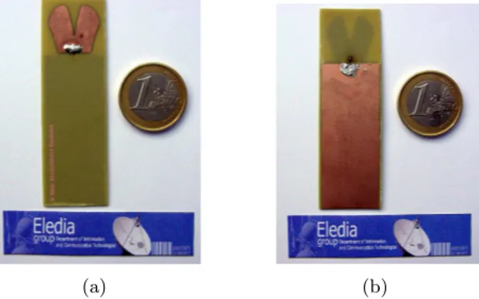
Figure 1: Antenna prototype. (a) Front view. (b) Back view.
of third-degree polynomials bm,3 S(t) = M X m=1 Sm(t) (1) where Sm(t) = 3 X k=0 bm,3(Pm−3+k,t) (2)
Pm= (xm, ym, zm) being the m-th control point and t is the curvilinear coordinate
on the contour S. Accordingly, the antenna geometry turns out to be described by means of the following array
x= {(xm, ym), m = 1, . . . , M ; w1, . . . , w4} (3)
where (xm, ym) indicates the planar coordinates of the m-th control point, M being
the total number of control points. Moreover, w1 is the substrate length, w2 is one
half of the substrate width, w3 is one half of the feedline width, and w4 the length
of the groundplane.
Parameters Optimization. In order to fit the antenna requirements concerned with the UWB impedance matching and absence of distortions, the array x in (3) is optimized by minimizing a suitable cost function Ψ (x)
Ψ (x) = Ψ|S11|(x) + Ψ|S21|(x) + Ψ∠S21(x) (4) where the first term, Ψ|S11|is concerned with the impedance matching
Ψ|S11|(x) = Z f2 f1 max ( 0,|S11(f )| − ^|S11(f )| ^ |S11(f )| ) df (5)
f1and f2 being the lower and upper frequencies of the band of interest, respectively;
Ψ|S21|and Ψ∠S21 weight the effectiveness of the antenna as a distortionless system
Ψ|S21|(x) = max ( 0,△ |S21| − ^△ |S21| ^ △ |S21| ) (6)
-35 -30 -25 -20 -15 -10 -5 9.2 9 8 7 6 5 4 3.7 |S11 | [dB] Frequency [GHz]
Requirement Simulated Data
Measured Data (a) -50 -45 -40 -35 -30 -25 -20 9.2 9 8 7 6 5 4 3.7 |S21 | [dB] Frequency [GHz] Requirement Simulated Data Measured Data (b) -200 -150 -100 -50 0 50 100 150 200 9.2 9 8 7 6 5 4 3.7 Arg(S 21 ) [deg] Frequency [GHz] Simulated Data Measured Data (c) 2.5 2 1.5 1 0.5 0 -0.5 -1 9.2 9 8 7 6 5 4 3.7 Group Delay [ns] Frequency [GHz] Requirement Simulated Data Measured Data (d)
Figure 2: Simulated and measured antenna prototype parameters. (a) S11 magnitude. (b) S21 magnitude. (c) S21 phase. (d) Group delay.
Ψ∠S21(x) = max ( 0,△τg− g△τg g △τg ) (7) Towards this end, an effective PSO-based procedure is used [8].
Numerical Results
In order to validate the effectiveness of the proposed technique, several antenna prototypes have been synthesized and built. As a representative result, simulated and measured performance of the prototype in Fig. 1 are discussed. Figure 2 shows the behaviours of the S-parameters. Simulated and measured results are in a reasonable agreement and they fit the project requirements in the bandwidth from f1 = 3.7 GHz up to f2 = 9.2 GHz. Moreover, the phase of the S21 turns out to be
approximately linear with a group delay characterized by a maximum variation of the order of 1 ns. For completeness, Figure 3 shows simulated radiation patterns on the horizontal and vertical planes at 4.0, 6.5 and 9.0 GHz. As it can be noticed, the antenna behaves approximately as omnidirectional radiator in the horizontal plane and it presents lower gain values in the vertical plane at 0◦ and 180◦ with a broadside simmetry.
Conclusion
In this work an innovative spline-based approach for the UWB antennas synthe-sis has been proposed. The flexibility and accuracy of the method allows a
re-10 0 -10 -20 -30 Gain [dBi] 0 30 60 90 120 150 180 210 240 270 300 330 Simulated (4.0 GHz) Simulated (6.5 GHz) Simulated (9.0 GHz) (a) 10 0 -10 -20 -30 Gain [dBi] 0 30 60 90 120 150 180 210 240 270 300 330 Simulated (4.0 GHz) Simulated (6.5 GHz) Simulated (9.0 GHz) (b)
Figure 3: Simulated antenna prototype radiation patterns. (a) Horizontal plane. (b) Vertical plane.
liable matching of UWB requirements. A representative design example described through the arising simulated as well as experimental electrical parameters has been presented in order to confirm the effectiveness of the approach.
References
[1] Z. N. Chen, X. H. Wu, H. F. Li, N. Yang, and M. Y. W. Chia, ”Considerations for source pulses and antennas in UWB radio system,” IEEE Trans. Antennas Propagat., vol. 52, no. 7, pp. 1739-1748, Jul. 2004.
[2] C. C. Lin, Y. C. Kan, L. C. Kuo, and H. R. Chuang, ”A planar triangular monopole antenna for UWB communication,” IEEE Microwave Wireless Compo-nents Lett., vol. 15, no. 10, pp. 624-626, Oct. 2005.
[3] K. Kiminami, A. Hirata, and T. Shiozawa, ”Double-sided printed bow-tie an-tenna for UWB communications,” IEEE Anan-tennas Wireless Propagat. Lett., vol. 3, pp. 152-153, 2004.
[4] J. Liang, C. C. Chiau, X. Chen, and C. G. Parini, ”Study of a printed circular disc monopole antenna for UWB systems,” IEEE Trans. Antennas Propagat., vol. 53, no. 11, pp. 3500-3504, Nov. 2005.
[5] J. M. Johnson and Y. Rahmat-Samii, ”Genetic algorithms and method of mo-ments (GA/MOM) for the design of integrated antennas,” IEEE Trans. Antennas Propagat., vol. 47, no. 10, pp. 1606-1614, Oct. 1999.
[6] F. J. Villegas, T. Cwik, Y. Rahmat-samii, and M. Manteghi, ”A parallel elec-tromagnetic genetic-algorithm optimization (EGO) application for patch antenna design,” IEEE Trans. Antennas Propagat., vol. 52, no. 9, pp. 2424-2435, Sep. 2004.
[7] C. De Boor, A Practical Guide to Spline. New York: Springer, 2001.
[8] R. Azaro, F. De Natale, M. Donelli, A. Massa, and E. Zeni, ”Optimized design of a multi-function/multi-band antenna for automotive rescue systems,” IEEE Trans. Antennas Propagat., vol. 54, no. 2, pp. 392-400, Feb. 2006.