FACOLTA’ DI INGEGNERIA
CORSO DI LAUREA SPECIALISTICA IN
INGEGNERIA ENERGETICA
DIEM
TESI DI LAUREA
in
Impiego Industriale dell'Energia e Cogenerazione LS
Tecnologie per il recupero energetico da motori
a combustione interna
CANDIDATO
RELATORE
Francesco Baldi
Chiar.mo Prof.
Michele Bianchi
Anno Accademico 2009/10
Sessione III
Abstract
Modern diesel engines used for agricultural applications have peak brake thermal efficiencies in the range of 40-42% for high-load operation with substantially lower efficiencies at road-load conditions. Some energy and exergy analysis can be found in literature revealing that the largest losses from these engines are due to heat loss and combustion irreversibility, and any improvement in engine efficiency requires reducing or recovering these losses. Unfortunately, much of the energy losses either occurs at low tem-peratures resulting in large entropy generation (such as in the radiator), are transferred to low-temperature flows (such as the oil and engine coolant), or are directly wasted to environment through radiation or convection. While the opportunity of recovering part of these losses for heavy-duty applications have already been demonstrated, the potential efficiency improvements de-riving from such a strategy for light-duty Diesel applications are unknown because of transient operation, the low thermal quality of exhaust gases at typical driving conditions, and the encumbrance of the added recovery system. We have used an experimental setup to perform a series of tests in order to investigate the potential for efficiency improvement through waste-heat recovery from the exhaust gas and the engine oil of a tractor Diesel engine. Results from steady-state and transient tests are presented, and the issues concerning waste heat recovery potential and its transient behavior are discussed for both engine oil and exhaust gas. An additional experi-mental setup, consisting of two heat exchangers placed respectively on the engine oil and exhaust gas, allowed to make some reflections about issues concerning the heat exchange, its inertia, and its influence over transient operations.
It would be impossible to cite here every single person who gave a contri-bution for me to have reached this far. Nevertheless, there are some people I would like to thank because of their special role in this specific phase of my career.
First of all I would like to thank St´ephanie Lacour, my tutor at Cema-gref, who have always been available to clarify my doubts, to discuss every problem and, most of all, who has always listened to what I told her and considered my opinion and my reflections as if they were made by a col-league. There is no doubt that I would not have achieved to complete this work without her.
A special thank is needed to M.George D´escombes and M.Michele Bianchi. They have positively reacted to my strong desire to participate to this project, and they have always been available for anything I needed for the possibility to study in France and spend my energies on this work.
Marc Hocquel and Cristophe Burgun have had a special role in my work too. They helped me in every single moment, they give me all the information I needed and followed my work and my mistakes with patience. One of the main features of my experience is the technical part, and it is thanks to them that I could not get lost in something in which I had no experience at all.
Thanks a lot to Romain, Wided, Sylvain, Alice, H´eloise, Florian, Simon, Alexandre, Morgane, Edoard, Lama, Samia, Fabien, Lela, Fran ˜A§ois, Mi-cael, Salem, Alfred, Fran, Olivier, Jean-Marie, Maurice, Sonia, Joel, Nadjat, and everybody is missing. Six months are a long time, and it is thanks to them if I have been able to go through all the little crisis everybody expe-rience during a research project.
A big, enormous thanks to all my friends. It is not possible to cite them all, but each of them, from the nearest to the farthest, played his role, gave me his contribution.
A final, special thanks to my parents. I hope they will understand my need of finding my way through the impervious adult life.
Contents
1 Waste heat recovery for Diesel engines 1
1.1 Introduction . . . 1
1.2 Diesel engine . . . 2
1.3 Waste heat recovery . . . 3
1.4 Specific features of agricultural applications . . . 5
1.5 Influence of heat exchange properties on recovery potential . . . 7
2 Exergy 9 2.1 First and second law of thermodynamics . . . 9
2.1.1 First law of thermodynamics: energy efficiency . . . 9
2.1.2 Second law of thermodynamics: entropy . . . 11
2.2 Combining First and second law together: exergy . . . 13
2.2.1 Exergy definition . . . 13
2.2.2 Maximum work potential: connection between energy and Carnot cycle . . . 15
2.2.3 Entropic temperature . . . 17
2.3 Exergy analysis . . . 21
2.3.1 Limits to exergy use . . . 21
2.3.2 Exergy analysis domains . . . 23
2.3.3 Exergy analysis for Waste Heat Recovery . . . 24
3 Testing equipment 27 3.1 Tractor . . . 31
3.2 Sensors . . . 32
3.3.1 Exhaust gas . . . 33
3.3.2 Engine oil . . . 35
4 Discussion 41 4.1 Steady state tests . . . 41
4.1.1 OCDE protocol . . . 42
4.1.2 ISO 8178 protocol . . . 42
4.2 Experimental measurements . . . 45
4.2.1 Exhaust gas experiments . . . 45
4.2.1.1 Temperature . . . 45
4.2.1.2 Mass flow . . . 46
4.2.2 Engine oil experiments . . . 46
4.2.2.1 Temperature . . . 46
4.2.2.2 Volumetric flow . . . 48
4.3 Steady state exergy potential evaluation . . . 48
4.3.1 Exhaust gas . . . 48
4.3.2 Engine oil . . . 54
4.4 Transient tests . . . 58
4.4.1 Exhaust gas . . . 61
4.4.2 Engine oil . . . 65
4.4.3 Test bench accuracy . . . 68
4.5 Influence of heat exchange properties on recovery potential . . . 72
4.5.1 Heat exchange exergy analysis . . . 72
4.5.2 Hot side . . . 73
4.5.3 Cold side . . . 75
5 Conclusions 79 6 Perspectives 81 6.1 Engine oil temperature evolution: engine thermal model . . . 81
6.2 Thermal exchange . . . 84
A Coefficients and parameters 85
CONTENTS
C Exhaust gas composition approximation 91
D Measurement accuracy 95
D.1 Temperatures . . . 95 D.2 Exhaust gas mass flow . . . 97
1
Waste heat recovery for Diesel
engines
1.1
Introduction
Climate changing due to greenhouse effect and pollution, both caused by human activi-ties, are subjects that concern the human kind more and more. The agricultural sector is responsible of a wide variety of emissions causing environmental problems: CITEPA report (3) pointed out that 14.2% of nitrogen oxides, 14.5% of VOCs (Volatile Organic Compounds) and 50.3% of PM10 are connected to agricultural activities, and in par-ticular to agricultural machinery. Greenhouse effect emissions of CO2 have also to be
taken into account: this contribution, even if small (2.8%), has been growing over the entire 20th century and has raised up by 167% since 19601.
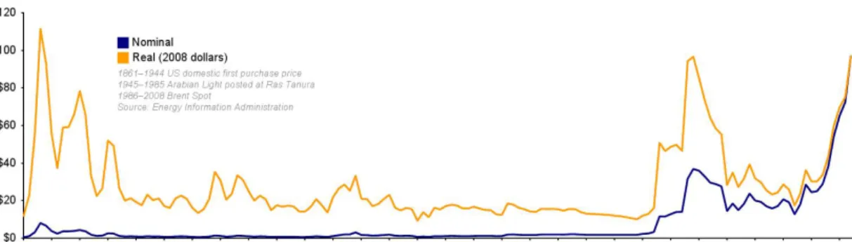
However, environmental concerns are not the only reason for which further research on Diesel engines for agricultural machinery is needed. The raise in oil prices, for example, is directly connected to petrol and Diesel fuel cost to consumers: as figure 1.1 shows, oil price can change dramatically in a phew years because of political and economical circumstances, and its tendency has been constantly increasing since 1998. It is clear that, if prices are not going down in a phew years, fuel consumption too will become a major economic output in the economic balance of agricultural activities.
1
Unfortunately, a part from the case of N Ox (62%), CITEPA report do not specify in what part Diesel engines are responsible of these emissions. Still, chosen data refers to the typical pollution coming from agricultural machinery. In the case of greenhouse emissions, in fact, only CO2 was brought as example, since the largest contribution (methane emissions) almost entirely comes from husbandry
Figure 1.1: Oil prices tendance during recent history: in blue the official price, in orange the price updated with reference to inflation (1)
These facts drive to increase efforts toward pollutant emissions and fuel consump-tion reducconsump-tion for agricultural machinery. Polluconsump-tion-based issues can be solved by the use of technological solutions specially conceived to reduce emissions, such as N Ox
catalyzed or non catalyzed reactors (SCR or SNCR), or filters for particulate matter. However, both pollution and fuel consumption can be reduced by increasing energetic performances of agricultural machineries, in particular with respect to Diesel engines.
1.2
Diesel engine
Invented at the end of XIXth century by Rudolf Diesel, a German engineer, the Diesel engine is an internal combustion engine.
Fuel ignition is the main feature distinguishing it from its petrol-fueled “brother”. Diesel engines, in fact, make use of a compression ignition rather than a spark one. In a gasoline-engine, air and fuel enter the cylinder together during the intake stroke. This prevent a large increase in pression, since high temperatures attained in the cylinder would cause fuel auto-ignition, thus leading to incomplete combustion. In Diesel en-gines, instead, air enters the cylinder alone during intake stroke, which means that no matter what pressure is attained during compression, there will not be auto-ignition. This leads to the possibility to attain much higher pressures, which directly implies a higher efficiency. Fuel is injected when the compression phase has almost completed and the air has attained a temperatures of about 700-900°C, enabling fuel to go through a rapid vaporisation followed by an almost instant combustion. The possibility of de-creasing vaporisation time and enhancing air-fuel mixing in combustion chamber have
1.3 Waste heat recovery
been, since Diesel engine invention, the most researched fields, and results of engineers efforts led to a large increase in Diesel performances.
As said, Diesel engine has a higher efficiency than its gasoline brother, even using a lower quality fuel. However, higher pressures imply a thicker structure and, as a consequence, heavier components and lower rotating speed. These features, typical of old Diesel engines, restricted their use first to marine and railway applications, and than to large vehicles such as trucks and tractors. Furthermore, pollution connected to particulate matter emissions caused by incomplete combustion has always been a primary issue for Diesel engines, and its solution is coming to light only in last years.
Turbocharger is maybe the most important innovation in Diesel engine technology. It consists of a gas turbine recovering exhaust gas thermal and pressure energy content, and of a compressor bringing inlet air to a higher pressure level, thus increasing engine power–to–weight ratio. This invention, together with the increase in atomisation in fuel injection, allowed a strong enhancement in Diesel engine performances. Engine weight reduction and a faster response to user’s instructions thus allowed to spread its application to the enormous market of private cars.
1.3
Waste heat recovery
Still, Diesel engine is far from perfection. Researchers are still working hard in order to increase its performances.
In the context of the reduction of fuel consumption, waste heat recovery (WHR) is considered to be a possible strategy to achieve this result.
The second principle of thermodynamics states that every engine or thermodynamic cycle converting the thermal energy of a heat source into work must waste a certain amount of heat to its environment. Once the hot source and the renvironment tem-peratures are fixed, the Carnot efficiency allows to estimate the maximum fraction of work that can be extracted from a given quantity of heat.
However, nowadays, engines and, more generally, devices for energy conversion performances are far away from Carnot efficiency. This means that, very simply, a lot of the available heat that could be converted into useful work is instead wasted.
In a Diesel engine there are several sources of waste heat: exhaust gases, engine oil, transmission fluid, cooling water, intercooler, EGR, etc; several authors, such as
Bourhis et al. (4), Edwards et al.(2), Junhong et al. (5), Gopal et al. (6), Srinisvan et al. (7), have already studied the possibilty of recovering a part of the wasted heat, concluding that WHR for Diesel engines is a possibility that is worthed for further inspection.
Before starting the project of a WHR system it is important to estimate the recovery potential of each of the available sources, in order to understand if some of them are more energetically and economically convenient to be exploited than others. But before starting with measures and calculations, a small summary should be made about the WHR sources that are to be taken into account.
Exhaust gas is normally the most valuable source of waste heat. In a Diesel engine combustion takes place inside the cylinder, and energy released pushes the piston up to the end of the cylinder. When the engine movement pulls back the piston, reducing combustion chamber dimensions, it drives exhaust gas through the exhaust valve out of the cylinder.
In a basic Diesel engine, the gas runs directly toward the exit of the exhaust pipe. However, in modern applications, a phew systems can be placed between the cylinder and the exit, such as pollution-reducing equipments. Anyway, no matter what is placed before its exit (in conventional engines), exhaust gas is still far from a state of thermal and mechanical equilibrium with environment, which means that a certain quantity of its energy content could still be recovered.
Exhaust gas outlet temperature, pressure and mass flow can widely change as a function of engine type, equipments and load factor. Just as a general consideration, the higher the engine efficiency, the lower its exhaust gas temperature.
As well as every industrial and technological applications, Diesel engines are pro-vided with several secondary system, whose nature and properties depend on engine type. However, for what concern this study, every Diesel engine is provided with a lubricating oil circuit.1
Engine oil is stocked in a vessel called “carter”, placed under the engine. A pump takes the oil from the carter and drives it throughout a circuit eventually spraying it over moving parts, in order to lubricate and cool them. Engine oil temperature can
1
In standard applications, cooling liquid is not pure water but a mix of water and glycol, the objective of the latter addition being to give antifreeze capabilities to the fluid. However, from now, water-glycol mixture will be referred to simply as water
1.4 Specific features of agricultural applications
reach very different values depending on engine type and operation, but generally it does not exceed 130°C, while its normal temperature stays around 110°C at full load operations. Oil cooling is assured by a heat exchanger placed on the water circuit.
1.4
Specific features of agricultural applications
As every technical application, Diesel engines for agricultural machinery have their own typical features, which have to be well known in order to understand the issues they are connected to.
The most typical feature of a tractor is the fact that, in several applications, power consumption is not strictly related to tractor displacement. During working operation, in fact, most of power absorption is related to the working equipment pulled by the tractor. This is possible thanks to a second shaft, directly connected to the engine and coaxial with tractor shaft, that transfers mechanical energy from the engine to the agricultural equipment. The two shaft movements are normally independent, which means that it is possible for the tractor to move while the equipment is not working, as well as the latter to do his job while the tractor is not moving. The shaft connection between the tractor and its equipment is generally placed beside the vehicle and it is called “power take-off” (PTO).
This feature is important in order to understand engine’s transient behavior. One of tractors specific features is, in fact, their particular kind of transient opera-tions. Tractors are generally used alternatively for two different goals, each having its specific features:
On the field, for pulling and giving energy to agricultural equipments On the road or on the field, for transporting goods
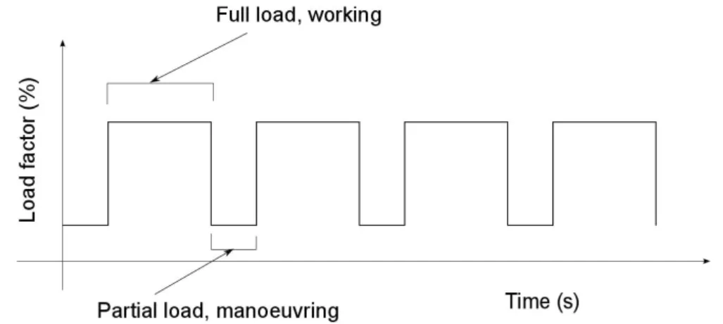
The main difference lays clearly in load factor variation with time. In fact, normal operations of agricultural machines on the field involve a periodical variation for engine load:
Full-load operation, when tractor is moving with its equipment working
Partial-load operation, typically in maneuvering operations, when equipment is not working
Figure 1.2: Sample of load factor evolution over a simulated on-field operation cycle
This is schematically shown in figure 1.2. However, this representation is not com-pletely veritable. In fact, even if full load conditions are well represented by a constant-load behavior, the same cannot be said for maneuvering operations, where evidence is shown of a very unsteady and unpredictable behavior. Concerning road transportation instead, load behavior is much more variable, more similar to that of cars. For such cases an example of engine speed changing with time, taken from Edwards’ paper (2), is shown in figure 1.3
Figure 1.3: Vehicle speed over a simulated warm UDDS drive cycle (2)
The two different components of standard real-life operations can mix in very dif-ferent ways, depending on several variables such as field dimensions, kind of crop, and many more.
These features make agricultural machines behavior in transient operation very dif-ferent from other applications employing Diesel engines, such as cars, trucks, ships and trains. This reasoning leads to the idea driving this study; Diesel steady-state behavior
1.5 Influence of heat exchange properties on recovery potential
do not change dramatically between different applications, being mainly related to some general features that could normally make possible to compare car, truck and tractor engines. The typical features in real-life operations are what really makes the difference, involving variable load conditions and a strong influence of transient behavior
It is therefore important to know what is the transients impact on WHR potential, in order to make a correct choice of all system parameters1.
1.5
Influence of heat exchange properties on recovery
po-tential
Heat recovery potential has been defined, until now, as the energy content of some sources of heat dispersion to the environment for an engine. However, even if the technological side of this matter has still to be treated, there is one first and important issue that need to be considered in order to give a correct evaluation of the real recovery potential of a heat source. Most of WHR strategies in fact need to transfer the energy content of a heat source to a new fluid, specifically meant for working in a recovery cycle. The matter of waste heat recovery is therefore directly connected to the subject of heat exchange properties of different fluids and materials.
In the case of WHR recovery for a Diesel engine, this matter comes strongly to the point. It is well known in fact (and it will be proved in the following chapters of this work) that exhaust gas is the most valuable source of waste energy, both for quality and quantity, and its high temperature makes it a much stronger candidate than engine oil for waste heat recovery2. However, it is likewise well known that heat transfer properties are not the same for liquid and gas flows, the latter having a much lower attitude in heat exchanging. Exhaust gas, therefore, generally require higher exchange surfaces in order to recovery their energy content.
This reasoning lead to the need of studying the subject of heat exchange with deeper interest. In static applications, in fact, the only constraint is generally related to economic-related issues, since the larger the heat exchanger the more expensive it
1a strong influence of transient duration could, for example, be solved using a high thermal capacity fluid for an intermediary cycle in order to increase system inertia
2As will be further explained in the following chapter, in fact, higher temperatures directly lead to a higher potential in work production
is.1 For moving applications, instead, other issues become important, mainly related
to exchanger’s weight and size. On a vehicle, in fact, room available is limited, and increasing the total weight has a direct influence on its performances.
This is why two heat exchangers (whose features will better described further ahead) have been inserted, the hot flow being either the engine oil or the exhaust gas circuits, and the cold flow being water coming from aqueduct. For both of them the surface and the main features of the exchanger were kept, in order to limit the analysis to each flow heat exchange properties. Measuring the temperature difference over the heat exchanger and the mass flow on both sides allows to have an experimental knowledge of heat exchange properties of both exhaust gas and engine oil, thus being able to insert these data to the rest of the analysis.
1
This is a general statement that largely simplifies the complex subject of heat exchanger choice. Lots of other parameters, such as the need of a pumping system, the attitude of fouling and, in general, lowering heat exchange properties with use, and many more, have an influence on the choice and the price of a heat exchanger
2
Exergy
2.1
First and second law of thermodynamics
2.1.1 First law of thermodynamics: energy efficiency
Since their first invention, systems for energy conversion have gone through an enor-mous growth in their use across all the industrialized countries. From steam engines to modern gas turbines, the possibility to produce useful work by burning specific sub-stances has dramatically spread, both in terms of quantity and variety of applications. This discovery is among the basis of the modern society in which we all live.
Nevertheless, especially during last years, an increasing concern regarding climate changes, fossil fuel depletion, and, in general, sustainable development, led to spend more and more resources in order to improve these systems energy performances, thus cutting down their fuel consumption.
Historically, energy analysis has always been the most used strategy for estimating engines performances. It leads to the energy efficiency, a value that allows to estimate the amount of useful energy produced by a system compared to its primary energy consumption.
Energy analysis comes from a balance between inlet and outlet energy flow in a well-defined system. The first law of thermodynamics says in fact that energy cannot be created or destructed, but only exchanged or transformed. The following is an example of a balance equation for an open system:
(ep+ ek+ h)im˙i+ (ep+ ek+ h)om˙o+
X
j
˙
where ep is gravity potential energy, ek is kinetic energy end h is enthalpy1 2.
A first possible definition for energy efficiency can be obtained by considering every inlet quantity as an energy source (putting them at denominator) and every outlet quantity as an energy product (putting them at numerator). We can in this case get to the following equation:
ηen=
˙
W + (ep+ ek+ h)om˙o
(ep+ ek+ h)im˙i+PjQ˙j
(2.2)
In most part of technical applications for energy production, though, these hypoth-esis can be made:
Mechanical work is the only useful product. In most of application, in fact, the outlet flow has only a small amount of energy left, it is just rejected to the environment. and it is not considered to be a useful product3
Variations in gravity potential energy and kinetic energy can normally be ne-glected4
The system is supposed to be adiabatic, since this is often a good approximation that allows to simplify calculations
These hypothesis lead to the following expression for energy efficiency:
ηen=
˙ W him˙i
(2.3)
Equation 2.3 is used when a system is being considered in his integrity, where the inlet flow is a fluid with high energy potential, such as a fuel or hot steam. However, if we want to focus on cycle efficiency and there is no need to give a definition of the
1Every thermodynamic property mentioned above is written in minuscule letters in order to repre-sent specific properties, as conventionally used
2
In this equation the thermodynamic convention was adopted by considering as positive quantities the work produced by the system and the heat received by the system
3
This is the case, for exemple, of exhaust gas of internal combustion engines, where combustion products leaving the cylinders are of no use and rejected in atmosphere. Some particular engines, such as plane gas turbine, do not match with this statement since, in this case, the exhaust gas kinetic energy is the useful product
4They become relevant only in some specific applications, such as in hydraulic turbines or in turbo-gas jet engines
2.1 First and second law of thermodynamics
heat source, a generic energy inlet (usually in the form of heat) can be considered. In this case energy efficiency is given by:
ηen= ˙ W ˙ Q1 (2.4)
where ˙Q1 is the amount of heat pumped into the system per time unit.
Finally, energy efficiency gives very valuable information, quantifying what part of available energy can be transformed into useful energy 1.
2.1.2 Second law of thermodynamics: entropy
The energy analysis is interesting but, often, incomplete. The first law of thermody-namics gives in fact information about quantities in energy exchanges, but does not show in which direction they naturally take place. As Mago says, “thermodynamics explain us that different kinds of energy are not the same”(9). This statement drives to look for other means to more effectively evaluate energy systems performances. What is really needed, in fact, is a way for taking into account of the difference in quality between different energy forms.
As said before, in fact, energy cannot be neither created nor destructed, but it can be exchanged and transformed among its different forms. For example, it is possible to get work from potential energy through an hydraulic turbine, or to have thermal energy from kinetic energy through a fan, etc.; it is only necessary to use the correct conversion system.
However, a form of energy exist that is different from others: thermal energy. Like every other form of energy, such as mechanical, kinetic, electric etc., thermal energy can be associated, at microscopic level, to particles movement. But unlike any other form, thermal energy movement is disorganized.
Thus, transforming thermal energy into any other energy form means converting a disorganized movement into an organized one (that is what take place, for exam-ple, in a turbine). This process lead to significant losses, that are directly connected 1Generally speaking, the most correct way to write the equation for energy efficiency is to put at numerator what is considered to be a valuable product, and at denominator what is considered to be a valuable resource. Lior (8) makes reference to a more specific definition, where he considers as a product everything that has an economic value and as a resource everything which has to by paid for. However, this definition is very useful for an economic estimation of a system, but do not give enough information when we are interested in thermodynamic performances
to the conversion process, which means that there is no way to get rid of them. A 100% conversion from thermal energy to, for example, mechanical energy is simply not achievable, even with ideal reversible engines.
This feature of thermal energy is resumed by the second law of thermodynamics; the Kelvin statement says that “No process is possible in which the sole result is the absorption of heat from a reservoir and its complete conversion into work ”.1.
The equation defining the second law involves the use of a new thermodynamic property: entropy, which is a measure of disorder at molecular level in a system:
dS =X
j
δQj
Tj
+ δS (2.5)
It is easy to notice that entropy, unlike energy, is not conserved. Every process leads to a creation of entropy (that is an increase in disorder of the system) that can be equal to 0 in the best and ideal case of reversible processes. This can lead to other statements of the second law, which say that “in an isolated system entropy can only increase” or, more dramatically “entropy of universe is increasing ”.
As can be seen in equation 2.5, entropy is a quantity strictly connected to heat exchanges. There are no modifications in entropy when heat is not involved. Work, for example, involves only an organized particle movement, that as no influence on the disorder of a system and, consequently, on its entropy.
The second law of thermodynamics establish a difference in quality between thermal energy and other energy forms, explaining why some processes can take place naturally while others cannot. Temperature is the thermodynamic property of matter that is of particular interest in this context. It measures thermal equilibrium, that is the ability to determine which of two or more systems will experience an increase in disorder level if they come to the condition of being able to exchange energy.
Being capable to effectively use entropy could be very helpful in energy system analysis, since it is able to quantify the irreversible effects causing efficiency losses. However, entropy concept is quite difficult to manipulate in practical applications, since it is a rather abstract property and, what is more important, it is not directly connected to energy, that is actually what interest us the most.
1
The other original statement, the Clausius one, says that “No process is possible whose sole result is the transfer of heat from a body of lower temperature to a body of higher temperature”. The equivalence of the two statement can be demonstrated(10). In this study the Kelvin statement was chosen because it is directly related to the subject
2.2 Combining First and second law together: exergy
2.2
Combining First and second law together: exergy
2.2.1 Exergy definition
In previous paragraphs, the two laws of thermodynamics have been introduced. Their content can be summarized as following:
The first law says that “You can’t get something for nothing (11) (Conservation of energy)
The second law says that “You can’t even get all you pay for (11) (Entropy creation)
A question arises: if you cannot get all you pay for, how much can you actually get?
What we are looking for is a thermodynamic property, such as entropy or enthalpy, allowing to estimate the potential to produce work from a given quantity of energy in the light of the second law.
This property is called exergy, defined as “The maximum theoretical work that can be extracted from a given entity when it is brought to equilibrium with its environment ” One of most important exergy features that arises from this definition is that the exergy content of a certain entity is not only connected to entity itself, but also to its environment. In his paper about exergy, Scott (12) gives a very simple but clear example: taking a cylinder full of air at atmospheric pressure and putting it anywhere on earth, its exergy content will be equal to 0. But if the same cylinder is brought on the moon or deep under the sea, even if its energy has not changed, its exergy has dramatically increased. Others examples, related to temperature, can be a glass of hot water or an ice cube: they both have way different exergy contents in summer and winter, which means depending on the environment state the system is surrounded by. Therefore, exergy can also be seen as a measure of departure from environment. The higher the difference of temperature, pressure, altitude, velocity etc. between the system and its environment, the higher its exergy content.
Exergy can be very useful to estimate the performances of several industrial sys-tems, since it allows to compare different forms of energy, and to measure system’s efficiency with reference to the maximum obtainable value. Several authors, such as
Rosen (13),(14),(15), Dincer (14), and Bejan (16), developed and used exergy analysis for this goal.
Time as come to pass to equations. Rosen (13) and Bejan (16) give a very proper demonstration of exergy concepts, that will be here reported.
Starting from balance equations for energy and entropy:
him˙i− hom˙o+ X i ˙ Qj− ˙W = 0 (2.6) sim˙i− som˙o+ X j ˙ Qj Tj + ˙S = 0 (2.7)
the contribution of heat exchange with environment Q0 can be obtained from equation
2.7: ˙ Q0 = T0[som˙o− sim˙i− X j6=0 ˙ Qj Tj − ˙S]
This expression can be inserted into the energy balance equation:
˙ W = him˙i− hom˙o+ X j6=0 ˙ Qj + T0[som˙o− sim˙i− X j6=0 ˙ Qj Tj − ˙S] = (h − T0s)im˙i− (h − T0s)om˙o+ X j6=0 ˙ Qj(1 − T0 Tj ) − T0S˙
This expression can be simplified thanks to the following reasoning:
As maximum work is the value we are looking for, reversible conditions have to be considered and thus entropy generation should be equal to 0
Outlet state is the state of equilibrium with environment, as settled by exergy definition
Since we are looking for the work that can be extracted from a generic mass flow, the system should be considered to be adiabatic
The system is in steady state, which means that ˙mi = ˙mo
These hypothesis lead to the following expression:
˙
2.2 Combining First and second law together: exergy
That is:
˙
ex = (h − h0) − T0(s − s0) (2.8)
This simple demonstration shows a very interesting aspect of energy. If only work is introduced into a system, exergy changes as following:
∆ex = W
If a given quantity of heat is introduced instead, exergy change is given by:
∆ex = Qj(1 −
T0
Tj
)
where Tj is the temperature of the heat exchange Qj. The asymmetry between heat
and work, as well as between thermal and mechanical energy, is here quantified. In this sense, exergy put together energy and entropy concepts: while the first gives information about quantity, but not quality and the second does the opposite, exergy is able to quantify energy quantity with an eye kept on its quality. Exergy analysis also explains, once again, that even the most effective thermal engine cannot convert all the energy content of a given quantity of thermal energy into work. A part of it is always lost, despite engine quality, and it is called anergy.
2.2.2 Maximum work potential: connection between energy and Carnot
cycle
In classical thermodynamics maximum work potential is estimated using a Carnot cycle. However, in this case, this is not directly possible. In fact, since the goal is to evaluate the work potential of a given quantity of matter, this will necessarily involve a thermal exchange leading to an evolution in fluid temperature, which is incompatible with a Carnot cycle.
Nevertheless, these two concepts must have something in common, since they are supposed to measure analogous quantities. That is what in fact happens, and this connection will be explained in the following paragraphs.
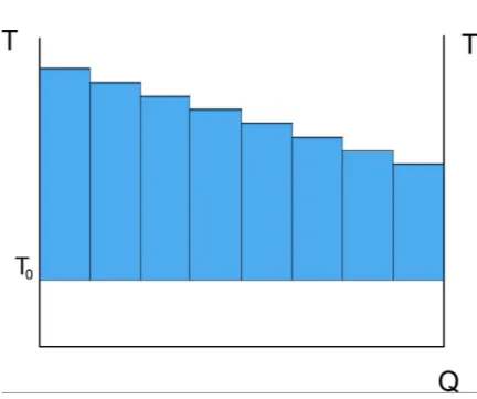
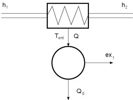
Consider a thermal exchange between two different flows. It is possible to suppose to divide the exchange in several smaller ones, each of them at a constant temperature (Fig. 2.1). Each of these exchanges can be considered as a Carnot cycle between exchange temperature and ambient temperature. Measuring the surface of the cycle
Figure 2.1: Sub-division of a thermal exchange in smaller exchanges at constant temper-ature
2.2 Combining First and second law together: exergy
lead to an estimation of the amount of work that could have been harvested by the Carnot cycle (Fig. 2.2). Therefore, this value represents the work production potential (exergy) lost by the hot flow because of the heat exchange. So:
exl,j = ηCarnot,jδQ = (1 −
T0
Tj
)Tj∆s
where ηCarnot,j, Tj, and exl,j are respectively the Carnot efficiency, the temperature
and the exergy loss of the j-heat exchange. The total of exergy loss caused by heat exchange value is:
exl= X j exl,j = X j (1 −T0 Tj )Tj∆s
If the heat exchange subdivision is brought to an infinite number of smaller cycles, an integral expression is obtained:
exl= Z B A (1 −T0 T )T ds that is: exl= Q − T0(sB− sA)
Given that a heat exchange is being considered, where the only way for energy transfer is through heat exchanges, the result is the following:
exl= (hA− hB) − T0(sA− sB) (2.9)
This is the same expression as 2.8, obtained thanks to the estimation of the work of a Carnot cycle, thus making evidence of connection its with exergy.
2.2.3 Entropic temperature
The Carnot cycle is composed by 4 processes:
Isentropic compression Isothermal heating Isentropic expansion Isothermal cooling
Of course, the Carnot cycle is ideal. Performing an isentropic compression or expan-sion means having access to totally adiabatic components with no friction losses. It is to be noted, however, that these restraints are connected to technological imperfection. Isothermal heat exchanges, instead, are way more difficult to achieve. To make them possible, it has to be that:
The flow has an infinite thermal capacity
Flow pressure decreases in order to keep temperature constant Heat exchange takes place during phase transition
Having an infinite thermal capacity is clearly not possible1, and being able to decrease pressure precisely enough to keep a constant exchange temperature is not only difficult, but also unseemly. Instead, several industrial applications make use of transition-phase heat exchanges, for different reasons; however, this is only a particular case, that cannot be taken as the general one.
Therefore, in general, heat exchanges lead to temperature variations that do not fit to a Carnot cycle. Therefore Carnot efficiency cannot simply be used as a reference of maximum efficiency, since it is needs to define precise temperature values for heat exchanges, that are not well defined in common cycles.
However, it is possible to find two equivalent temperatures, called entropic tem-peratures. The cycle resulting from this choice must respect two restraints face to the original cycle:
Same difference in entropy
Same amount of heat injected into the cycle Same amount of heat rejected by the cycle
To make this possible, each entropic temperature must be equal to:
Ten=
Q ∆s
1having a very high thermal capacity face to the heat exchanged is indeed possible, but rarely useful in industrial applications
2.2 Combining First and second law together: exergy
It is therefore possible to have a maximum and a minimum entropic temperature (called respectively Ten,max and Ten,min) permitting to evaluate an equivalent Carnot efficiency
as following:
η = Q(1 − Ten,min Ten,max
)
where Q is the amount of heat injected into the cycle.
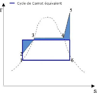
Figure 2.3: Example of an equivalent Carnot cycle for a Hirn cycle
This concept can be applied to exergy analysis. As already said, in fact, the exergy content of a given quantity of matter in a given state is the maximum work that can be harvested by bringing it to equilibrium with its environment. This can be seen as nothing more than a thermodynamic cycle between the initial state (1) and the equilibrium state (0). As every thermodynamic cycle, it can be associated with an equivalent Carnot cycle between two entropic temperatures. Given that exergy is the maximum amount of work that can be harvested, just like work produced by a Carnot cycle, this expression is obtained:
ex = (h − h0)(1 −
T0
Ten,max
It easy to notice that this expression leads to the same result of equation 2.8. This can be seen by performing the calculation of entropic temperature in the ideal gas hypothesis. This leads to:
Ten = Q ∆s = = cp(T − T0) cplnTT0 = = (T − T0) lnTT 0
that, when subsituted in equation 2.10, gives exactly the same result as equation 2.8.
Figure 2.4: T,s diagram showing the comparaison between the exergy content and the Carnot cycle associated to the entropic temperature of the cycle
In figure 2.4 the comparison between the two concepts is shown, highlighting the cycles’ output work. In figure 2.5 an example of an ideal cycle made for exergy es-timation is shown. This model, anyway, is only valid where state 1 is at the same pressure as its environment, since evidently a heat exchanger is not able to recovery pressure differences. In this case exergy is calculated as the work produced by a Carnot engine working between ambient temperature and entropic temperature of the ther-mal exchanges bringing the considered mass flow from its original state to therther-mal equilibrium with environment.
2.3 Exergy analysis
Figure 2.5: Cycle diagram showing the role of entropic temperature in exergy calculation
Therefore, entropic temperature can be a good system to estimate quality and quan-tity of energy, with respect to the second law, just as exergy is. Entropic temperature can be very useful because it is easier to understand and it allows to make a more direct comparaison between different heat sources.
2.3
Exergy analysis
In previous paragraphs exergy has been introduced, giving its definition, explaining its meaning, and showing why other thermodynamic properties, such as energy and entropy, are adequate for estimating energy quantity and quality at the same time. Exergy, as said before, is helpful for making comparisons between thermal energy and other forms with respect to their quality.
However, one important remark need to be made. Exergy is not the ultimate solution for estimating energy quality, and its use needs to be restrained with respect to its limits.
2.3.1 Limits to exergy use
Firstly, exergy is strictly connected to heat exchanges and thermal energy. It allows to compare them with work and mechanical energy (as well as with other energy forms
such as electrical or kinetic) with respect to their difference in quality. This means that if a process makes no use of thermal energy, exergy analysis will not give any further information than a simple energy analysis. This can be the case of power plants such as hydro-electrical systems or wind turbines, where no heat exchange is involved. A good example of this issue is shown in Dincer’s paper entitled “Energy and exergy utilization in transportation sector of Saudi Arabia”(17). In this case kinetic energy is the final product which is considered in the exergy analysis, where the chemical energy of the fuel is the inlet flow. Exergy and energy have identical values in both cases, leading to identical results for energy and exergy efficiency. Therefore, in this case, there is no point in using exergy efficiency. More interesting results would be obtained in the case of a thermodynamic study of engines: in this case, heat transfers come to light and an exergy analysis reveal interesting aspects of the system.1
Secondly, the fundamental principle of exergy analysis is the major value given to work as process consumption or product. This statement, that thermodynamically speaking is always true, can drive to incorrect conclusion from the technological and economical point of view. In fact, in the industrial sector, several processes only need heat at a certain temperature as process utility, which means that there is no point in comparing product quality with work potential. A very good example is given by house heating sector. If only the system for hot water production is considered, it is clear that a conventional boiler has an efficiency way higher than a heat pump, since it is theoretically capable to produce a hot stream at 300-400°C. But if the whole heating system is considered, in particular the final part, it is also clear that a system combining a heat pump with radiant panels can be way more effective than a conventional boiler provided with a radiator system. In this case, in fact, even if the exergy of the outlet flow is different, both systems manage to achieve the same result, and only inlet exergy consumption should be taken into account.
Thirdly, a very important aspect that should be taken into account is the choice of the environment state. A precise and proper definition of the environment state is very important. When considering heating systems, for instance, the fact that external
1
The only difference in Dincer paper lies in the γ coefficient, representative of the ratio between HHV (Higher Heating Value) and LHV (Lower Heating Value) of considered fuel. This is simply due to different conventions: in energy analysis the energy content of a fuel is represented by the LHV, while in exergy analysis it is measured by the HHV
2.3 Exergy analysis
temperature substantially changes throughout the year must be taken into account. Bibliography gives important examples of how results become very different whether a correct analysis of the environment state is performed or not. In Dincer’s paper entitled “Energy and exergy use in public and private sector of Saudi Arabia” (18) a very low exergetic efficiency is associated to the air conditioning sector. The issue here is strongly connected to the choice of the environment state: choosing a fixed temperature of 10°C, as Dincer does with reference to previous papers, leads to a misunderstanding, since Saudi Arabia’s climate features much higher temperatures. This reasoning implies that the need of air conditioning at 20°C is connected to a “cold“ exergy rather than a “hot“ one. Choosing 10°C as reference temperature means that a flow of cold air at 20°C as a lower exergy content than one at 30°C, while the real condition is the opposite. A way more precise approach is used in Wall’s paper “Exergy conversion in the Swedish society” (19). In this case the author develops a quite simple model for estimating external temperature depending on the season and the moment of the day. This tool allows a very precise evaluation of heating system exergy content, that as said in previous sections strongly depends on the environment state. Le Goff et al. (20) go into this subject in depth, explaining the existence of several strategies for defining environment temperature and comparing their advantages and disadvantages. What is pointed out in this latter paper, is that the maximum efficiency of a generic energy system do not depend on its environment. This concept allows, however, to estimate maximum efficiency, while real efficiency depends, in fact, on environmental conditions, as pointed out in previous paragraphs.
2.3.2 Exergy analysis domains
It is therefore important to identify what domains exergy analysis is more suitable for. One of the analysis that could take most advantage of the exergy application is the study of systems energy consumption. In this case, in fact, we have often to face with complex processes that need different energy sources, such as electrical, thermal and mechanical energy, and a simple energy-based analysis of these different needs would be unfair. Even if this domain has been largely studied in the past and in present years, Szargut work “Exergy analysis of thermal, chemical, and metallurgical processes” (21) still remains the reference study. The main feature of this specific analysis is that major attention is pointed on exergy consumption, where the goal is to minimize it for a given
product. In this case, thus, the exergy content of entries rather than of products is generally taken into account.
Another possible use for exergy analysis comes from a secondary definition. Exergy is in fact also representative of the “departure from environmental state”, and several authors, such as Rosen, Dincer (22) and Lior (8), make reference to the use of exergy in environmental impact analysis. This concept can be very useful when considering thermal pollution, but also (considering the chemical part of exergy), for evaluating pollutants reactivity and its impact on the environment. In this case, however, it is important to notice that only the energy aspect is taken into account, while there is no mention of toxicity or other process by-products features. This means that this analysis, even if correct and useful, remains incomplete.
2.3.3 Exergy analysis for Waste Heat Recovery
In this study attention will be concentrated on exergy analysis applied to the evaluation of recovery potential in WHR systems where additional work is required. This is maybe the domain exergy analysis is best fit for, since it allows an estimation of maximum work potential of a current, which is exactly what has to be evaluated to define the efficiency of this kind of WHR systems.
In fact, several authors followed this path. Concentrating on WHR from Diesel engines, which is the subject of this study, Aly (23), Bourhis et al.(4), and Edwards et al.(2) made use of exergy analysis, pointing out the differences with reference to the energy analysis, in this field.
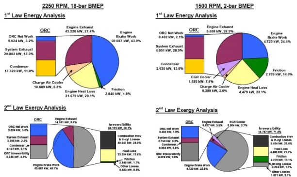
In figure 2.6, taken from Edwards’ paper (2), these differences become clear. What is easy to notice is that exergy recovery potential is much lower than energy one (In this study the author chose to take into account only EGR and exhaust gas recovery potential, without any interest in engine oil). This result becomes obvious under the light of previous sections: the second law of thermodynamics clearly explains that there is no way to convert all heat into work, and that the portion that can definitely be converted depends on flow temperature and is quantified by exergy. In Edwards’ paper, for instance, it can be seen that the 69 kW of energy output in form of work keeps the same value in exergy analysis, while the 43 kW of energy output in form of waste heat (EGR and exhaust gas) become only 15 kW of exergy flow.
2.3 Exergy analysis
Figure 2.6: Energy and exergy analysis results in Edwards’ paper
(2)
In Bourhis paper (4), instead, exergy and energy analysis are more detailed and the repartition between different waste flows is more complex (more contribution are explicitly evaluated, such as intercooler, oil, cooling water etc.). Anyway, results do not substantially change: several irreversible processes lead to exergy destruction (energy degradation), and only a small part of waste heat can be recovered.
Ending the chapter, there are a phew points on which further studies are necessary:
The recovery potential, as well as thermodynamic properties that characterize mass flows (temperature, enthalpy, entropy, etc.) strongly depends on engine load operating point. This shows the need to investigate more on how much this actually concerns the possibility of waste heat recovering and in how transient operations can influence the choice of the WHR system that should be adopted
In Edwards’ paper, only EGR and exhaust gas waste heat was recovered in system simulations. Other studies, instead, consider also the possibility to exploit energy content in cooling water or engine oil. This choice depends on several parameters, but one of major importance, that is often neglected, is the surface needed by
heat exchangers. Further considerations have to be done in order to understand whether it is possible to conceive a recovery system on outlet flow that have a very low exchange coefficient, such as for exhaust gases, in a situation where space and weight are limited, such as on tractors.
Exergy analysis is not enough to make a complete evaluation on the convenience of a WHR system. In fact, apart from exergy content of an outlet flow (that is possible to estimate without reference to the WHR system), exergetic efficiency of the exchange has to be considered because of its large influence on system per-formance. In this context, even low-exergy currents can be useful, for instance, in order to heat up the thermovector fluid and thus to enhance the exergy efficiency of the heat exchange placed on higher-exergetic flows
3
Testing equipment
TSAN (Technologies for safety and performance of agricultural machinery) unit in Cemagref research center of Antony disposes of two test benchs for tractors.
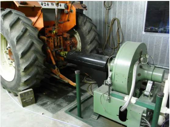
Figure 3.1: Tractor rear view. Focus on the PTO shaft connection and the electric brake
Selected test bench, normally used for standard performance tests (OCDE), is pro-vided with a water cooled electric brake, based on Foucault currents, which is able to
raise up to 400 kW of brake power. The connection between the electrical brake and the tractor’s engine is granted by a direct connection to the power take-off (PTO). A focus on the PTO shaft connection with the electric brake is shown in figure 3.1. Cooling water for the brake is circulated by a pump which drives it to two external heat exchanger, meant to cool it down if its temperature rises over 30°C.
Other test bench main features are listed below
Engine performance sensors for engine torque, speed and brake power Thermocouples for temperature measurements1
A gas aspiration system (Figure 3.2) allowing to power up the engine inside the test bench building without any danger for operators
Control strategy: both direct online control and input-file control are available Interface: results are shown directly on the screen and saved on output files Test bench has been also recently provided with a gas-analyser, allowing an online measure of exhaust gas temperature, composition and pressure (Figure 3.3
Each sensor is connected to a main section (Figure 3.4) where all signals are chan-neled to the main processing unit. Each signal is treated in order to make it available to test controller, permitting a direct check on variables evolution with time.
Test bench is also equipped with an emergency stop system, connecting the tractor to test controller position. In case of any dangerous or unexpected system behavior, it is always possible to suddenly turn off the engine by simply pulling a metal wire.
Test bench software “duck” allows to command the tractor engine with a control over these parameters:
Torque
Rotating speed Throttle Power
1All thermocouples have been calibrated thanks to a calibrating system and a reference sensor. This allowed to define linear correction coefficients for the sensors that needed
3.1 Tractor
Figure 3.4: Sensor box
Instructions are given by controlling two of these parameters at once, that are chosen depending on test needs. Every instruction over the variation of a parameter must be associated to a transient-duration instruction, that means telling the software how much time the engine must take to pass from the operational condition A to B.
3.1
Tractor
The tractor is a Renault 851-4 R 7664, shown in figure 3.5. It is provided with a 4-cylinder engine, of 4156 cm3 of volume (cylinder cross section: 105 cm2, stroke: 120 cm). It is provided with a turbo-compound system exploiting exhaust gas energy and it is automatically lubricated. Measures taken at the test bench gave the following results:
Nominal power : 57.5 kW
Speed at nominal power : 2350 rpm
Torque at nominal power : 233.4
Maximum power : 57.5 kW
Maximum torque : 277 Nm
Figure 3.5: Renault 851-4 R 7664
3.2
Sensors
A certain number of standard measures are taken for every kind of test, therefore being available for this study too. It si the case of:
Temperatures :
Ambient air Air filter Fuel Engine oil
Engine cooling liquid Mass flows : fuel
3.3 Heat exchangers Engine parameters : Power Engine torque Brake torque Engine speed Brake speed
3.3
Heat exchangers
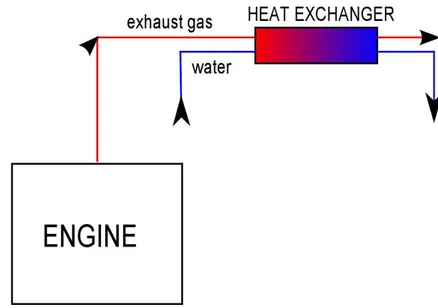
3.3.1 Exhaust gasThe first heat exchanger is placed on the exhaust gas circuit in order to estimate its recovery potential. A schematic view of this system is shown in figure 3.6
Figure 3.6: Schematic model of the heat exchanger for exhaust gas experiments
The heat exchanger is made of a copper pipe (diameter: 1 cm , length: 41 cm) concentric to the exhaust pipe, connected to a water circuit coming from the lab tap and leading to the waste drain. Inlet and outlet temperature for both the hot and the cold side are measured. Type K thermocouples (chromel - alumel) were used on the hot side, the temperature of the flow being able to reach more than 400°C, while normal
type T (copper-constantan) thermocouples have been used for this circuit. Figure 3.7 shows a picture of the practical realization of this device
Figure 3.7: Heat exchanger and gas analyzer for exhaust gas experiments
For every measure other than temperature, such as pressure and mass flow, HORIBA OBS-2200 gas analyser was used, which allowed an online measurement and data up-loading, strictly necessary feature with respect to this study. It allowed in particular to measure gas mass flow, pressure and composition.
The OBS-2000 series, apart from measuring exhaust gas temperature, also calcu-lates mass emissions for CO, CO2 (NDIR analyzer without water extraction), THC (FID analyzer), NOx (CLD analyzer), and fuel consumption. OBS features include an
3.3 Heat exchangers
exhaust flow meter, based on a Pitot tube, a GPS receiver for global positioning data and other sensors to monitor engine parameters and atmospheric conditions in real time. However, for this work, only temperature and mass flow measures were directly used, while data concerning exhaust gas composition were employed for a repeatability analysis.
For this exchanger, thermal insulation was very difficult. Exhaust gas temperature is too high to allow the use of a thermal coating, thus making it impossible to reduce the strong influence of heat exchange with the environment.
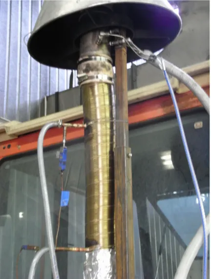
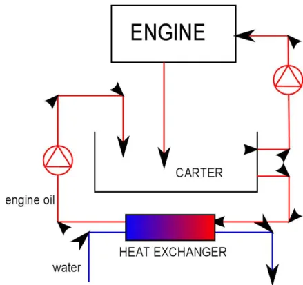
3.3.2 Engine oil
The second heat exchanger is placed on the engine oil circuit in order to estimate its recovery potential. A schematic view of this system is shown in figure 3.8
Figure 3.8: Schematic model of the heat exchanger for exhaust gas experiments
Oil is driven out of the carter toward the heat exchanger first through a metal pipe, then through a rubber one. After passing through the heat exchanger, oil is then processed by a pump allowing him to go up to the top of the carter, where the fluid
is put back into the storage, closing the circuit. The pump is powered by a rectifier at 20V DC rather than at its nominal voltage (24 V, DC) in order to reduce oil mass flow that would risk, otherwise, to empty the heat exchanger. Furthermore, if oil mass flow became too high, water flow would not be able to cool it, leading to no difference between oil inlet and outlet temperatures. Water coming from the lab tab is driven through a rubber pipe to the heat exchanger, after which another rubber pipe drives it to the waste draining. For technical reasons the heat exchanger is set with a parallel-flow arrangement, despite its lower exchange efficiency. Anyway the exchange surface and, thus, the heat exchanged is too low for this to have a real negative influence on the matter.
Figure 3.9 shows the practical solution adopted for the engine oil heat exchanger Five thermocouples are placed on engine oil circuit:
Oil, temperature in the carter
Oil, heat exchanger inlet temperature, placed on the rubber pipe between carter exit and heat exchanger entrance 1
Oil, heat exchanger outlet temperature, placed on the rubber pipe between heat exchanger exit and pump
Water, heat exchanger inlet temperature, placed on the rubber pipe before the heat exchanger
Water, heat exchanger outlet temperature, placed on the rubber pipe after the heat exchanger
All thermocouples were calibrated with reference to a standard one, using a specific device, in order to have the maximum available instrumental precision. Thermocouples of type T (copper-constantan) have been used for this circuit.
A value for engine oil mass flow is needed in order to correctly evaluate energy and exergy quantities. A mass flow measurement system is therefore necessary. For the engine oil circuit the sensor is placed just after the pump, and the result is directly
1
Originally, the thermocouple was directly placed on the metal pipe, without any use of rubber pipe in this part. The changement in system configuration was caused by the high thermal capacity of the metal pipe, that was remarked to influence oil temperature measurement
3.3 Heat exchangers
shown on controller interface. Concerning the water circuit, the measure is taken at the end of the circuit, just before the waste draining1.
The variations measured in water mass flow led to adapting a different solution. Water circuit was equipped with an intermediary storing system, meant to increase system inertia and, thus, to reduce variations in water mass flow. The height at which the storing system was placed was of primary importance for defining water flow. This parameter was set to a value allowing to have a mass flow low enough to see variations in temperature, but high enough to fill the pipe, thus making the exchange easier to be described analytically.
Water and engine oil mass flow setting was a quite important subject discussed at the beginning of the test series. This quantity should in fact be set to a value allowing to measure a temperature difference between inlet and outlet flow high enough to get rid of measure incertitude. Thermocouples available at Cemagref test bench have, in fact, a measurement incertitude of about ± 1°C, which means that a difference in temperature between inlet and outlet flow of less than approximatively 5°C would be strongly affected by measurement incertitude. At the same time, mass flow should be high enough to allow the fluid to complete fill-up the pipe, since it would be otherwise impossible to give a correct estimation of the exchange surface. Moreover, decreasing the mass flow over a certain limit would cause troubles in its measurement.
First measurements led to a dramatically strong impact of the heat exchanger non-adiabatic behavior, making it very difficult to separate the two components. For this reason the heat exchanger, initially set with the configuration shown in figure 3.9, has been thermally insulated. Two different levels of thermal insulation were inserted:
A coat of a low-conductive material (normally used for heating pipes insulation), for reducing undesired heat exchanges due to conduction. The same material have been used for pipes insulation, in order to reduce as much as possible the temperature drop between the engine oil inside the carter and at the inlet of the exchanger
1This makes mass flow measures response quite slow. However, in normal operations no variation in water mass flow should happen, which means that, theoretically, water mass flow measurement is inserted only for being able to initially set the flow, whose regulation is granted by manually opening a vane. However in real operations, variations in water mass flow have been measured during the tests. This can be caused by several phenomenons, first of all the stochastic variations caused by non-constant value of aqueduct pressure
3.3 Heat exchangers
An external annular protection for reducing undesired convection. One of the most unexpected and undesired problems was, in fact, the strong forced-convective heat exchange cause by tractor fan. Air flow passing through the fan is, in fact, driven directly above the carter, where the heat exchanger is placed. This heat exchange has been reduced by a merely physical protection surrounding the ex-changer and, thus, preventing the air flow coming from the fan from directly impacting the exchanger
Figure 3.10 shows the heat exchanger after the insulation process.
Figure 3.10: Heat exchanger and oil pump
These arrangements, together with the efforts to approach the thermocouples as much as possible to the inlet and outlet sides of the exchanger (thus reducing the influence of the heat exchange with air) made it possible to isolate the interesting phenomenon, that is the heat exchange between engine oil and water and the exchanger thermal inertia.
The other, strong issue related to the heat exchanger placed on the engine oil circuit is its thermal inertia. Firstly, in fact, engine oil itself tends to slowly react to variations in heat transfer. Furthermore tests results showed that the exchanger, whose external wall is made of a thick layer of cast iron, has a different inertia, making the modeling of the totality of the exchange even harder.
4
Discussion
Waste heat recovery potential of the engine of a tractor was the subject of this work. It will be structured in three main sections:
Steady state potential analysis : In the first part, the steady state exergy potential of both engine oil and exhaust gas will be evaluated, in order to write a chart of engine speed and power dependence of this potential.
Transient potential analysis : In the second part, the transient behavior of the exergy potential will be evaluated. The comparaison between a simple steady-state analysis and a more exhaustive transient one will be performed, in order to have a better understanding of the unsteady phenomena influence on heat recovery potential.
Heat exchange features : In the third and latter part of this project, heat exchange issues will be studied, and the influence of the different heat exchange properties of the two flows will be evaluated
4.1
Steady state tests
The first part of test series was meant to understand engine’s behavior for certain specific operational points in steady state conditions. The analysis of these tests results allows to have a general knowledge of engine parameters dependence of its waste heat recovery potential.
The operational points chosen for the tests are representative of all of the possible working points of the engine, starting from idle conditions to its maximum power. However, operational points belonging to two already existent procedures were tested: the OCDE and the ISO 8178 protocol.
4.1.1 OCDE protocol
The OCDE protocol is a standard series of 6 test points originally developed in order to give a substantial estimation of engine fuel consumption over its life operations, allowing comparisons among different tractors. Even if some studies, such as the Cemagref report “Energy consumption of tractors: Remarks over OCDE and ISO 8178 protocols”(24), proved the incomplete effectiveness of this protocol, the operational conditions it takes into account are still an interesting starting point for defining engine performances. These points are defined as following:
1. 100% Pnom 2. 80% Pnom 3. 80% Pnom et 90% ωnom 4. 40% Pnom et 90% ωnom 5. 60% Pnom et 60% ωnom 6. 40% Pnom et 60% ωnom 4.1.2 ISO 8178 protocol
The ISO 8178 protocol is a second standard series of 8 points developed instead for pollutant emissions evaluation. It includes:
1. 100% Cnom et 100% ωnom
2. 75% Cnom et 100% ωnom
3. 50% Cnom et 100% ωnom
4.1 Steady state tests
5. 100% Cmax et 100% ωCmax
6. 75% Cmax et 100% ωCmax
7. 50% Cmax et 100% ωCmax
8. idling
Other points were inserted in order to get a chart wide enough to be representative of the entire operational range. All points taken into account for the following analysis are listed in table 4.1 and shown in figure 4.1
Figure 4.1: Engine power versus speed chart for steady state test points
As seen in the first chapter, exergy is the tool allowing to estimate the maximum work potential. However, the word “maximum” is not casual: in a real recovery system, only a part of this maximum potential can effectively be harvested by the system. Anyway, the objective of this work is to evaluate recovery potential, without interest to what kind of system is used for this purpose.
Protocol Power Speed rpm KW 0.0 2350 ISO 8178 5.7 2350 ISO 8178 28.8 2350 OCDE 46.0 2350 OCDE, ISO 8178 57.0 2350 0.0 2115 OCDE 23.0 2115 OCDE 46.0 2115 54.4 2115 0.0 1900 20.0 1900 40.0 1900 49.6 1900 0.0 1640 16.0 1640 ISO 8178 18.3 1640 ISO 8178 32.2 1640 ISO 8178 45.7 1640 0.0 1410 OCDE 23.0 1410 OCDE 35.0 1410 39,2 1410 18,4 1300 27.7 1300 37.0 1300 0.0 1300 0.0 950 10.8 950 18.9 950 ISO 8178 0.0 780
4.2 Experimental measurements
As said in chapter 2, he reference equation for this kind of calculation is the follow-ing:
˙
ex = ˙m(h − h0) − T0(s − s0) (4.1)
where 0 label corresponds to equilibrium state with reference to environment. For all steady-state and transient tests, a temperature of 298.15 K and a pressure of 101325 Pa is chosen for reference conditions. This choice is driven firstly because room tem-perature at the test bench showed to vary in a range close to 298.15 K, and secondly because this is a standard value1 in thermodynamics.
Equation 4.1 allows to evaluate the exergy potential of a current once its enthalpy and entropy value are known. It is however important to keep in mind that even exergy is a measure of the real amount of work it is possible to extract, but only an ideal one achievable only with reversible processes and no losses.
4.2
Experimental measurements
In order to have real data on which basing every following calculation and reflexion, a number of test series was performed. The test bench, the tractor and all the ex-perimental devices used for this purpose are described in chapter 3. The choice of the properties and variables which were measured during these tests was based on the need for recovery potential evaluation, in terms of the exergy of each studied flow, the reference equation being the 4.1.
Two different sources of waste heat were taken into account during these tests: exhaust gas and engine oil
4.2.1 Exhaust gas experiments
4.2.1.1 Temperature
Because of its low thermal inertia, the steady state value of exhaust gas temperature could be directly measured during the experimental phase of this study. It was therefore possible to have a good approximation of the steady-state value without any need of mathematical intermediation.