A MODEL PREDICTIVE CONTROL ARCHITECTURE FOR
AN UNMANNED ELECTRIC VEHICLE
Relatore: Ing. Matteo MATTEUCCI Correlatore: Ing. Luca BASCETTA
Tesi di Laurea di:
Pietro BALATTI Matr. 837376 Alessandro CIANFEROTTI Matr. 836855
averci aiutato all’inizio del nostro lavoro. Infine, vogliamo ringraziare l’AIRLab e tutti i ragazzi che si sono susseguiti nel corso di questi mesi per aver animato le nostre giornate in laboratorio.
Pietro e Alessandro
Il mio primo pensiero non può che andare ai miei genitori, Piera e Ulisse, che hanno sempre creduto in me supportando le mie scelte e cercando di indirizzarmi sempre sulla via che ritenevano più corretta, senza tuttavia impormi mai nessuna decisione. Li ringrazio in particolare per avermi trasmesso valori e passioni che fanno di me quello che sono, l’aspirazione a sognare in grande e la forza di non arrendersi mai di fronte alle difficoltà. Il modo in cui mi hanno supportato e aiutato a superare questo periodo difficile dal punto di vista salutare ne è il più grande esempio.
Ringrazio la splendida grande famiglia di cui faccio parte, zii/e e cugini/e. Siamo tutti consapevoli di avere una famiglia speciale e unica, che non perde l’occasione per festeggiare e che si stringe forte e compatta in ogni momento di difficoltà. Credo che questa sia una delle più grandi fortune che si possano desiderare; grazie di cuore a tutti voi, perché ci siete stati in momenti bui e perché so che ci sarete sempre a condividere momenti di gioia e soddisfazione come questo.
Ricordo tutti gli amici e coinquilini che mi hanno accompagnato in questi anni. Grazie a Gnagneo che mi ha insegnato cos’è l’assurdo, alla squadra di Zii e Nipoti che mi ha trasmesso valori importanti nella vita quali l’essere RIC, ai Fratelli Grimm che mi hanno insegnato a raccontare fiabe e in generale a tutta la compagnia di Giancarlos che con caparbietà non ha mai smesso di lottare per il Trofeo. Non dimentico anche chi c’è sempre stato e che ora è fisicamente dall’altra parte del mondo, ma sentimentalmente ancora qui.
Un pensiero particolare va a Lisa che è la persona che mi è stata più vicina in questi anni; avrei preferito scoprirlo in altri modi, ma ho capito che sarà un grande medico da ogni punto di vista.
Ricordo le persone che hanno reso la mia vita universitaria più piacevole e con cui ho condiviso intere sessioni di esami e anni di lezioni, in particolare Toto e Vale. L’università mi ha anche dato l’opportunità di svolgere una delle esperienze più belle della mia vita, l’Erasmus a Valencia; senza di voi non sarebbe stato lo stesso: grazie ai boludos Lorenzito y Fede.
Per ultimo, non in ordine di importanza, ringrazio Cianfe, con cui ho condiviso lo sviluppo di questa tesi ma non solo; da vero amico non ha mai dubitato di intraprendere questo percorso nonostante le difficoltà che sapeva avrebbe potuto comportare.
Pietro Milano, dicembre 2016
Un ringraziamento speciale va a mio nonno Gianfranco per avermi accompagnato lungo tutto il percorso universitario e per avermi sempre dato importanti lezioni di vita. Ringrazio anche i miei zii, Maria e Biagio, che considero come dei secondi genitori e mia cugina Genoveffa per essersi sempre interessati ai progressi del mio percorso. Voglio ringraziare anche mio nonno Elia per avermi insegnato, attraverso le sue gesta, i valori della famiglia.
Grazie a Denny, Luchino, Sorbi e Mauro, per aver condiviso gioie e sofferenze durante le sessioni di esami e per aver reso la mia esperienza universitaria più piacevole.
Dedico l’ultimo ringraziamento, ma non in ordine di importanza, al mio amico Pietro, compagno di tesi e di viaggio, con cui ho avuto l’onore di vivere e condividere la parte finale dalla mia esperienza universitaria. Un pensiero speciale va a lui per avermi insegnato a non mollare mai e per essere stato un esempio di forza e tenacia.
Alessandro Milano, dicembre 2016
was validated under ideal conditions. We developed also a localization system necessary to test our system in a simulation environment. The development of the software architecture has been done using the well-known and widely used framework for robotics ROS (Robot Operating System). Taking advantage of the flexibility of the ROS framework, we integrated ROAMFREE (Robust Odometry Applying Multisensor Fusion to Reduce Estimation Errors) in our architecture, which is a library for multisensor fusion and pose estimation. To verify and analyze the system behavior in control conditions, we have developed two simulators: one representing an ideal and simplified situation, exploiting the mathematical description of the single-track model, and one using Gazebo, a simulator that allows to model complex scenarios. The contribution of this thesis can be divided in four parts: the first one regards the general architecture, the second one is relative to the vehicle modeling, the third one is dedicated to the vehicle localization and the fourth one concerns the MPC controller. The overall design of the control architecture has been validated through an extensive experimental activity performed within the two simulation environments.
Keywords: Unmanned vehicles, Model Predictive Control, single-track,
ROAMFREE, Gazebo, odeint, CPLEX.
Il lavoro di questa tesi parte da un controllore MPC precedentemente sviluppato in un’altra tesi tramite l’utilizzo di un linguaggio di program-mazione a più alto livello, MATLAB. E’ stato quindi necessario convertirlo ripensando all’architettura in modo da ottimizzare le sue performance ed aumentarne la sua modularità. E’ stato poi implementato un sistema di localizzazione necessario per poter testare il sistema in un ambiente di simulazione.
Lo sviluppo dell’architettura è stato effettuato usando un framework per la robotica noto e ampiamente utilizzato, i.e., ROS (Robot Operating Systems), caratterizzato da un’elevata modularità, implementata con lo stile architetturale publish-subscribe, e dalla disponibilità di diversi moduli già sviluppati e testati. Ciò ha permesso di sviluppare un’architettura flessibile appropriata per un prototipo, che può essere sottoposto a svari-ate modifiche durante il suo sviluppo, rimanendo comunque un sistema sufficientemente robusto e attuabile per un utilizzo a lungo termine.
ROS semplifica l’integrazione di più moduli sviluppati separatamente. In particolare, uno dei principali moduli che è stato integrato nell’architettura è ROAMFREE (Robust Odometry Applying Multisensor Fusion to Reduce Estimation Error), che è una libreria utilizzata per fare una fusione dei dati provenienti da diversi sensori con lo scopo di stimare la posizione di un robot. Oltre all’integrazione di questa libreria, è stato aggiunto un modulo proposto all’interno di un’altra tesi, chiamato fastPredictor, che partendo dalla posizione stimata da ROAMFREE integra le infor-mazioni di odometria per ottenere una stima più veloce e ridurne i ritardi di computazione.
Nel campo dei veicolo autonomi, il ruolo della simulazione risulta essere fondamentale. Prima di poter utilizzare il sistema su di un veicolo reale, è richiesta la verifica e analisi dello stesso. A riguardo, abbiamo simulato il funzionamento della nostra architettura su Gazebo, un simulatore che permette di modellizzare scenari complessi utilizzando anche modelli di robot preesistenti. Inoltre, Gazebo offre la possibilità di simulare diversi sensori e di interfacciarsi facilmente con ROS. Il risultato è un ambiente di simulazione che può sostituire completamente il veicolo reale e che permette di effettuare esperimenti complessi.
Il contenuto di questa tesi può essere diviso in quattro parti: la prima riguarda l’architettura generale, la seconda è relativa alla modellizzazione del veicolo, la terza è dedicata alla localizzazione e la quarta è inerente al controllore MPC. Prima di tutto forniamo una descrizione generale dell’architettura sviluppata, spiegandone la suddivisione e come avviene la comunicazione tra i vari componenti del sistema. Successivamente, analizziamo dettagliatamente la modellizzazione del veicolo e i vari step di simulazione dello stesso. Inoltre, nella stessa sezione, vengono descritti i sensori utilizzati ai fini della localizzazione. In seguito, viene illustrato il modulo riguardante la stima della posizione del veicolo, specificandone il funzionamento e come viene migliorato. Si fornisce successivamente una breve descrizione del MPC preso come riferimento per il nostro lavoro e la relativa implementazione in ROS. Nell’ultima parte della tesi è possibile trovare i risultati sperimentali ottenuti durante i test effettuati.
Parole chiave: Veicoli autonomi, Model Predictive Control, single-track,
1 Driverless cars state of the art 5
1.1 Unmanned vehicles . . . 5
1.2 Self-driving cars . . . 6
1.3 Existing projects . . . 9
1.3.1 First unmanned vehicles . . . 9
1.3.2 DARPA Grand Challenge . . . 12
1.3.3 Modern self-driving cars . . . 15
1.3.4 Software architectures . . . 19
2 Software architecture 23 2.1 Relevant background . . . 23
2.2 Architectural overview . . . 27
2.2.1 Main modules . . . 29
2.2.2 ROS topics and messages . . . 30
3 Thesis reference robot platform 33 3.1 Relevant background . . . 33
3.1.1 Related works . . . 33
3.1.2 Physical simulation of vehicles . . . 36
3.1.3 Gazebo . . . 40
3.1.4 ODEINT . . . 43
3.2 Reference sensors . . . 46
3.2.1 Global Positioning System . . . 46
3.2.2 Inertial Measurement Unit and magnetometer . . . 47
3.3 Thesis vehicle simulators . . . 48
3.3.1 ODE based simulator . . . 49
3.3.2 Gazebo . . . 52
3.4 Sensors and actuators . . . 53
3.4.1 Global Positioning System . . . 54
3.4.2 Inertial Measurement Unit . . . 54
3.4.3 Magnetometer . . . 55
3.4.4 Ackermann Odometry . . . 55
3.4.5 Velocity and steering angle control . . . 56
4 Localization 57 4.1 Relevant background . . . 57
4.2 ROAMFREE setup and configuration . . . 60
4.2.1 Configuration . . . 61
4.2.2 GPS message conversion . . . 62
4.2.3 Estimation . . . 64
4.2.4 Fast predictor . . . 64
5 Model Predictive Control 67 5.1 Relevant background . . . 67
5.2 MPC . . . 73
5.3 Feedback linearization . . . 78
5.4 MPC implementation . . . 82
5.5 Sideslip angle estimation . . . 85
6 Experimental results 87 6.1 Parameters estimation . . . 87 6.1.1 Sideslip angle . . . 87 6.1.2 Cornering stiffness . . . 89 6.2 Localization . . . 90 6.3 Regulation problem . . . 93
6.3.1 ODE based simulator . . . 93
6.3.2 Gazebo . . . 95
6.4 Trajectory . . . 96
6.4.1 ODE based simulator . . . 98
6.4.2 Gazebo . . . 100
6.4.3 Ideal comparison . . . 101
7 Conclusions and future work 103 7.1 Future work . . . 103
1.3 The four best participants of the DARPA Grand Challenge 2005 edition: Stanley(a), Sandstorm(b), H1ghlander(c) and
Kat-5 (d). . . . 13
1.4 The four best participants of the DARPA Urban Challenge 2007 edition: Boss(a), Junior(b), Odin(c) and Talos (d). . 15
1.5 Some models of modern self-driving cars: AnnieWAY(a), DEEVA(b), Toyota Prius Google Car (c) and the Google Car model customized by Google. . . . 17
1.6 The two Tesla models, model S and model X, and a repre-sentation of the Advanced Sensor Coverage of every Tesla model. . . . 18
1.7 Annieway’s software architecture. . . . 20
1.8 Boss’ software architecture. . . . 21
1.9 Junior’s software architecture. . . . 22
2.1 The costantly growing ROS vibrant community. . . . 25
2.2 The Publisher/Subscriber protocol. . . . 26
2.3 Set up of the ROS communications. . . . 26
2.4 A typical rviz window. . . . 27
2.5 General software architecture. . . . 28
2.6 Sense-Plan-Act paradigm. . . . 29
2.7 Custom messages. . . . 31
2.8 Topics structure. . . . 31
3.1 Polaris Ranger XP 900 EPS. . . . 34
3.2 Some examples of self-driving projects involving golf cars:
Auro(a), USAD(b), SMART(c). . . . 35
3.3 Some examples of simulators for robotic applications: We-bots(a), V-Rep(b), OpenHRP3(c), MORSE(d), Dymola(e) and 20-Sim(f). . . . 39
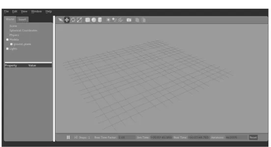
3.4 Main window of Gazebo. . . . 40
3.5 The Gazebo element hierarchy. . . . 42
3.6 Overview of the gazebo_ros_pkgs interface. . . . 43
3.7 GPS Garmin 18 LVC. . . . 47
3.8 IMU Xsens MTi. . . . 48
3.9 Single-track model. . . . 50
3.10 Polaris model in Gazebo. . . . 52
3.11 Polaris vehicle, sensors and coordinate frames. . . . 54
4.1 Localization architecture. . . . 58
4.2 Reference frames and coordinate transformations in ROAM-FREE. . . . 59
4.3 Hierarchy of the coordinate frames. . . . 62
4.4 Geodetic (yellow), ECEF (blue) and ENU (green) coordinates. 63 4.5 The class diagram of the fastPredictor node. . . . 65
4.6 The fastPredictor ROS communication flow. . . . 66
5.1 MPC package. . . . 68
5.2 Receding Horizon principle [7]. . . . 72
5.3 ∆δmax as function of the velocity v. . . . 76
5.4 Approximation of an obstacle with a regular polytope. . . . 77
5.5 Distances between the vehicle and the polytope edges. . . . 78
5.6 Block diagram explaining how the feedback linearization works. 79 5.7 Representation of the point P under control. . . . 80
5.8 Feedback linearization applied to the single-track model. . . 81
5.9 The sideslip angle β in the single-track model. . . . 85
5.10 Methodology for sideslip angle estimation through feedback linearization. . . . 86
6.1 Observer and single-track sideslip angle comparison. . . . . 88
6.2 Observer and real sideslip angle comparison. . . . 88
6.3 Single-track model. . . . 89
6.4 Empirical tyre curves: (a) front and (b) rear. . . . 90
6.5 Trajectory comparison among ideal position, GPS and ROAM-FREE. . . . 91
6.11 Trajectory of the vehicle with and without obstacle in Gazebo. 95
6.12 Trajectories of the vehicle with ROAMFREE with and
with-out noise: GPS std <0.1, 0.1, 0.1> (a), GPS std <0.3, 0.3,
0.3> (b). . . . 97
6.13 Trajectories of the vehicle with ROAMFREE with and with-out noise (with obstacle): comparison of various tests(a) and GPS noisy signal of one the tests (b). . . . 97
6.14 Trajectories comparison among the ideal situation in Gazebo, ROAMFREE affected by noise and ROAMFREE with fast-Predictor affected by noise. . . . 98
6.15 A waypoint trajectory followed by the ODE simulator. . . . 99
6.16 Velocity trend. . . . 99
6.17 Steering angle trend. . . . 99
6.18 Trajectories comparison in Gazebo. . . . 100
theoretically lead to many improvements in transportation. There are, however, many obstacles to successfully implementing the concept as a common and effective method of transportation. This is especially true in situations in which a car on autopilot would need to safely navigate alongside normal cars directed by human drivers. To be useful, a driverless car must be able to navigate to a given destination based on passenger-provided instructions, avoid environmental obstacles, and safely avoid other vehicles. There are many potential advantages to using a driverless car instead of a traditional human-controlled vehicle. A driverless car would not be subject to human error, one of the most common causes of car accidents. There would be little need for driver’s licenses, highway patrols, extensive traffic laws, and even stop signs or street lights. Such vehicles would not be affected by erratic human drivers and would, therefore, be able to drive very close together. This could lead to a situation in which high road density would not have a detrimental effect on speed, so many cars could travel close together while maintaining a high average speed.
The great improvement in control strategies and electronic equipment, which are becoming more and more efficient, powerful and economical, is one of the main reasons of the growing interest of various automotive brands in autonomous vehicles, which are no longer a dream, but can be reality in the near future. Another important development that has allowed the growth of this sector is the considerable progress in data elaboration and sensors, such as camera, radar, LIDAR, which are necessary for the autonomous perception.
In this thesis, the Model Predictive Control architecture of an
tonomous electric vehicle has been designed and developed together with the dynamic simulation used for its validation. The system has been real-ized at first using a single-track model and then simulating a real vehicle, i.e., a “Polaris Ranger XP 900”.
This technique exploits a model of the process under investigation to obtain the control output, through the minimization of an objective function under some operational restrictions. Model Predictive Control has been employed since the last years of the 70’s, mainly to control the processes in chemical plants and oil refineries. However, due to its prediction properties, MPC is very suitable for autonomous vehicle control applications. In fact, it calculates future changes of the state variables and related quantities, basing on the current measurements and the current dynamic state and these changes are used to compute the optimal control sequence.
The work of this thesis starts from an MPC controller already developed in an other thesis with a high-level programming language, MATLAB. It has therefore been necessary to convert it reorganizing the original archi-tecture in order to optimize its performance and to improve its modularity. Moreover we developed a localization system needed to test our system in a simulation environment.
Our goal has been to develop a flexible software architecture to make a vehicle reach autonomously a target point avoiding obstacles. In order to achieve a high level of modularity, the development of the software architecture has been done using a well-known and widely used framework for robotics: ROS (Robot Operating System). It is characterized by a high modularity, implemented with a publish-subscribe pattern, and the availability of several off-the-shelf modules. This allowed us to develop a flexible architecture suitable for a prototype, which could undergo var-ious modification during its development, while remaining a sufficiently robust and viable system for long-term use. Moreover, ROS simplify the integration of modules developed separately.
Since for autonomous driving the localization is crucial, among the modules we are interested in integrating we have ROAMFREE (Robust Odometry Applying Multisensor Fusion to Reduce Estimation Errors), which is a library for multisensor fusion and pose estimation. We use this library to implement a localization system and we couple it with a module developed within an other thesis that integrates odometry data to achieve a faster local estimate based on the absolute one provided by ROAMFREE.
Working with an autonomous vehicle, the role of the simulator is fun-damental. Before using the system on a real vehicle, it is required to verify
The contents of this thesis can be divided in four parts: the first one regarding the general architecture, the second one relative to the vehicle modeling, the third one dedicated to the vehicle localization and the fourth one concerning the MPC controller. First of all we provide an overview of the whole architecture describing how it is composed and how the communication among them is handled. Then, we analyze the vehicle modeling and the simulation steps. Moreover, in the same section, the sensors used to localize the vehicle are described. Afterwards, the pose estimation module is illustrated, specifying how it works and how the estimation is improved. Lastly, we provide a short description of the reference MPC and our relative implementation in ROS.
In the last part of the thesis it is possible to find the experimental results obtained during the tests we carried out.
Outline
In order to help the reader to better understand how to read this work here we suggest how to proceed. For every chapter it is provided an initial relative background of the covered topic. For those who already have the relative knowledge it is possible to skip the first section of the chapter.
The structure of this thesis is the following:
• Chapter 1: some examples of driverless vehicles proposed in literature, with a special focus on the DARPA Challenge, are described. More-over an More-overview of the main software architectures in unmanned vehicles is proposed.
• Chapter 2: an overview of the software architecture is described, followed by a brief description of each module developed or integrated. • Chapter 3: the reference vehicle and sensors are described.
Further-more there is a detailed description of the simulators.
• Chapter 4: the localization module is illustrated describing the ROAMFREE library configuration and its improvement.
• Chapter 5: the application of the Model Predictive Control technique for the reference vehicle control is described.
• Chapter 6: parameter estimation and experimental results are pre-sented and analyzed.
• Chapter 7: all the work done within this thesis is briefly summarized and some possible future extensions and improvements are presented.
From the very beginning of vehicles history, vehicular automation was one of the most pursued goals; nowadays numerous automatic system are included in aircraft, boats, industrial machinery and agricultural vehicles. However, fully autonomous ground vehicles able to navigate on rough terrain or complex and dynamic environments as city streets remain an ambitious goal. This kind of vehicles could improve everyday life, for instance reducing the risk of accidents, or they could be used to explore difficult to reached places such as mines or planets.
Unmanned ground vehicles (UGV) come in very different sizes and shapes depending on the task they have been designed to accomplish. Generally, they can be divided in two categories, those built on a custom platform and those based on a modified vehicle. In the latter category, over the years, various vehicles were used as base, like military vehicles, trucks, fuel-powered or electric automobiles, four-wheelers, and buses. Even if the world of UGV is quite diverse, they share some common characteristics:
• they are equipped with sensors to perceive the environment; • it is possible to remotely control the vehicle;
• they are able to perform some autonomous tasks.
When designing an autonomous vehicle some common problems have to be faced, namely how to control the actuators of the vehicle, how to fuse the information from the sensors to determinate its position and how to drive autonomously. Various approaches have been adopted in order to build and manage an UGV; in the following we present a section about
autonomous cars that belong to the unmanned vehicle category while maintaining they primary goal, i.e., transporting people.
1.2
Self-driving cars
For more than a century the automotive industry has contributed towards innovation and economic growth. In the last decade the momentum of innovation is phenomenal and the world is now at the cusp of greatest technological revolution: “self-driving” vehicles. The main focus is to keep the human being out of the vehicle control loop and to relieve him/her from the task of driving. The main components of self driving vehicles are sensors (to acquire information about vehicle surrounding), computers (to process sensor information and send warning/control signals) and actuators (responsible for lateral and longitudinal control). The basic responsibility of self driving cars include lateral and longitudinal control of vehicle along with vehicle to vehicle (V2V) and vehicle to infrastructure (V2I) communication. [55]
In 2013 the U.S. Department of Transportation’s National Highway Traffic Safety Administration (NHTSA) announced a new policy concerning vehicle automation where it has been proposed a formal classification of the existing systems. NHTSA defines vehicle automation as having five levels [75]:
• Level 0 - No-Automation: The driver is in complete and sole control of the primary vehicle controls – brake, steering, throttle, and motive power – at all times;
• Level 1 - Function-specific Automation: Automation at this level involves one or more specific control functions. Examples include electronic stability control or pre-charged brakes, where the vehicle automatically assists with braking to enable the driver to regain control of the vehicle or stop faster than possible by acting alone; • Level 2 - Combined Function Automation: This level involves
automation of at least two primary control functions designed to work in unison to relieve the driver of control of those functions. An example of combined functions enabling a Level 2 system is adaptive cruise control in combination with lane centering;
• Level 3 - Limited Self-Driving Automation: Vehicles at this level of automation enable the driver to cede full control of all safety-critical functions under certain traffic or environmental conditions.
vehicles.
Among the Full Self-Driving cars (Level 4) benefits we can list [2]: • Fewer accidents: humans can get distracted easily, computers do
not. Moreover, reaction time is larger for humans. Also we all know driving drunk is dangerous. Drowsy driving is just as risky or even more;
• No more parking worries: most cars are parked 95% of the time. Self-driving cars would eliminate the need for much of that parking. Best of all, you would get back all that time you now spend looking for parking;
• Less traffic congestion: autonomous cars by communicating with each other and with customized infrastructures would be able to manage the traffic by themselves. Moreover if you could use an app to get a car to come pick you up anytime, you might not feel the need to buy your own;
• Lower emissions: an estimated 30% – 60% of the cars driving around a downtown area are circling for parking. That’s good evidence that self-driving cars, which would not be cruising for a place to park, would lower emissions. If they also replace a good chunk of car ownership, that should further reduce emissions. Chances are that self-driving cars will also be electric, which will lower emissions even more;
• Savings: With self-driving cars, we are likely to save in several ways. Less car ownership certainly means savings: you will not have to spend on the car itself, repairs, or insurance. If your taxi or Uber comes without a driver, the ride will be cheaper. And another benefit of not having to park is that you do not have to pay to park. Plus, when fewer people own cars, they will not be as desirable to steal. And because driverless cars will be integrated and tracked in a network, it will be more challenging to steal them;
• Reduced stress: even driving enthusiasts get stressed by driving in bad traffic. Add the stress of finding parking, and it gets serious. In fact, it seems that stress from driving is even worse than we think. It can lead to adverse health effects and can even make you feel less satisfied with your job and with your life;
• Transportation for those who can not drive: self-driving cars will be a boon to the elderly, allowing them mobility and freedom far beyond what they enjoy now. They will also be great for people who can not drive because of other physical issues;
• Police and road signs reduction: autonomous cars will receive neces-sary communication via an electronic way;
• Higher velocity limits: due to a lower reaction time of an unmanned vehicle.
Despite the benefits brought by the use of autonomous cars, there are some technological and legal challenges that need to be overcome:
• Software reliability: depending totally from the software, self-driving cars must guarantee an high reliability rate to avoid malfunctions that can lead to accidents;
• Security: cyber-attacks on autonomous vehicles would put human lives at immediate risk in a way most other hacks do not [61]; • Radio spectrum need: to let the communication among the vehicles
be possible [41];
• Sensitivity to different weather conditions: the navigation system of an autonomous car shall adapt to different meteo situations, above all in case of snow or rain because in these particular conditions sensors are not fully reliable;
• Need of creating (and maintaining) maps for self-driving cars [1]; • Road infrastructures may need changes to work properly with
au-tonomous cars, e.g. traffic lights shall be able to communicate with cars;
• Privacy loss: car localization will always be tracked and other info will be shared with the other vehicles and with road infrastructures;
In this section we describe some existing projects from the very first unmanned vehicles to the modern self-driving cars. A specific subsection is dedicated to the DARPA Grand Challenge, a prize competition for American autonomous vehicles [18].
1.3.1
First unmanned vehicles
In the following we present the first unmanned vehicles projects; the first ones are more oriented to robots, while more recent ones are about real self-driving cars.
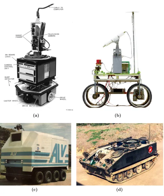
Shakey [45] (SRI International, United States, 1966-1972, Figure1.1a) is considered the first mobile robot capable of autonomous behavior. It was a wheeled platform equipped with steerable TV camera, ultrasonic range finder, and touch sensors. An SDS-940 mainframe computer performed navigation and exploration tasks, a RF link connected the robot to it. While the robot autonomous capabilities were simple, it established the functional baselines for mobile robots of its era.
Stanford Cart [42] [43] (Stanford University AI Lab, United States, 1973-1981, Figure 1.1b) was a remotely controlled TV-equipped mobile robot. A computer program drove the Cart through cluttered spaces, gaining its knowledge of the world entirely from images broadcast by an on-board TV system. It used a sophisticated stereo vision system, where the single TV camera was moved to each of nine different positions on the top of its simple mobility base.
DARPA Autonomous Land Vehicle [71] [42] (DARPA’s Strategic Computing, United States, 1985-1988, Figure1.1c) was built on a Standard Manufacturing eight-wheel hydrostatically-driven all-terrain vehicle capable of speeds of up to 45 mph on the highway and up to 18 mph on rough terrain. The sensor suite consisted of a color video camera and a laser
(a) (b)
(c) (d)
Figure 1.1: Some of the first prototypes of unmanned vehicles: Shakey (a),
Stanford Cart (b), DARPA ALV (c) and Ground Surveillance Robot (d).
(a) (b)
Figure 1.2: Two prototypes of autonomous car: VaMP (a) and ARGO (b).
scanner. Video and range data processing modules produced road-edge information that was used to generate a model of the scene ahead.
Ground Surveillance Robot [52] [26] (Naval Ocean Systems Center, United States, 1985-1986, Figure 1.1d) project explored the development of a modular, flexible distributed architecture for the integration and control of complex robotic systems, using a fully actuated 7-ton M-114 armored personnel carrier as the host vehicle. With an array of fixed and steerable ultrasonic sensors and a distributed blackboard architec-ture implemented on multiple PCs, the vehicle successfully demonstrated autonomous following of both a lead vehicle and a walking human.
VaMP [59] [20] [60] (Bundeswehr University of Munich, Germany, 1993-1995, Figure1.2a) is considered the first truly autonomous car, it was able to drive in heavy traffic for long distances without human intervention, using computer vision to recognize rapidly moving obstacles such as other cars, and automatically avoid and pass them. It was a 500 SEL Mercedes modified such that it was possible to control steering wheel, throttle, and brakes through computer commands, and equipped with four cameras. In 1995, the vehicle was experimented on a long-distance test from Munich (Germany) to Odense (Denmark), and it was able to cover more than 1600
km, 95% of which with no human intervention.
ARGO [35] (University of Parma, Italy, 1998, Figure 1.2b) was a Lancia Thema passenger car equipped with a stereoscopic vision system consisting of two synchronized cameras able to acquire pairs of gray level images, which allowed to extract road and environmental information for the automatic driving of the vehicle. The ARGO vehicle had autonomous steering capabilities and human-triggered lane change maneuvers could be
performed automatically. In June 1998, the vehicle was able to carry out a 2000 km journey on the Italian highways [3], 94% of the total trip was performed autonomously.
1.3.2
DARPA Grand Challenge
The DARPA Grand Challenge is a prize competition for American au-tonomous vehicles, funded by the Defense Advanced Research Projects Agency, the most prominent research organization of the US. Congress has authorized DARPA to award cash prizes to further DARPA’s mission to sponsor revolutionary, high-payoff research that bridges the gap between fundamental discoveries and military use. The initial DARPA Grand Challenge was created to spur the development of technologies needed to create the first fully autonomous ground vehicles capable of completing a substantial off-road course within a limited time. The third event, the DARPA Urban Challenge extended the initial Challenge to autonomous operation in a mock urban environment.
In the following paragraphs we list the most noteworthy projects that participated in the 2005 and 2007 editions.
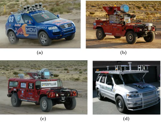
Stanley [9] (Stanford University, United States, 2005, Figure 1.3a) is an autonomous car that participated and won the second edition of the DARPA Grand Challenge in 2005. Stanley is based on a diesel-powered Volkswagen Touareg R5 with a custom interface that enables direct electronic actuation of both throttle and brakes. A DC motor attached to the steering column provides electronic steering control. It is equipped with five SICK laser range finders, a color camera for long-range road perception, two RADAR sensors, and a GPS positioning system. It was able to complete the 212 Km off-road course of the 2005 DARPA Grand Challenge in 6 hours and 54 minutes.
Sandstorm [6] (Carnegie Mellon University, United States, 2004-2005, Figure 1.3b) is an autonomous vehicle that participated at both editions of the DARPA Grand Challenge, the first in 2004, the second in 2005. Sandstorm is based on a heavily modified 1986 M998 HMMWV with drive-by-wire modifications control acceleration, braking and shifting. The sensors used in 2004 included three fixed LIDAR laser-ranging units, one steerable LIDAR, a radar unit, a pair of cameras for stereo vision, and a GPS. In 2005, three additional fixed LIDAR were added, while the stereo cameras were removed. In 2004, Sandstorm obtained the best result but covered only 11.9 Km, in 2005, finished the race in 7 hours and 5 minutes, placing second.
(a) (b)
(c) (d)
Figure 1.3: The four best participants of the DARPA Grand Challenge 2005
edition: Stanley(a), Sandstorm(b), H1ghlander(c) and Kat-5 (d).
H1ghlander [6] (Carnegie Mellon University, United States, 2004-2005, Figure 1.3c) Created by Red Team, the same as the previous one, it is a heavily modified 1999 HUMMER H1. It competed in the 2005 DARPA Grand Challenge. The sensors used by H1ghlander include LIDAR laser-ranging units, one steerable LIDAR (in the globe on top), GPS and an inertial navigation system. H1ghlander completed the race in 7 hours and 14 minutes, placing 3rd out of the five vehicles to complete the 132 mile (212 km) course. It was preceded, in second place, by Sandstorm, its sister vehicle with which shares the software and the sensors.
Kat-5 [58] (GrayMatter, Inc., United States, 2005, Figure 1.3d) is an autonomous car developed by a team comprising employees from The Gray Insurance Company and students from Tulane University. It participated to the 2005 DARPA Grand Challenge and finished with a time of 7 hours and 30 minutes, only 37 minutes behind Stanley. Kat-5 is a 2005 Ford Escape Hybrid modified with the sensors and actuators needed for autonomous operation. It uses oscillating LIDARs and information from the INS/GPS
unit to create a picture of the surrounding environment and drive-by-wire systems to control the vehicle.
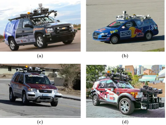
Boss[68] (Carnegie Mellon University, United States, 2007, Figure1.4a) is a heavily modified Chevrolet Tahoe. Boss is equipped with more than a dozen lasers, cameras and radars to perceive the world. It completed the 2007 edition race of the DARPA Urban Challenge in 4 hours and 10 minutes winning it with an average of approximately 23 km/h throughout the course.
Junior[69] (Stanford University, United States, 2007, Figure 1.4b) is a modified 2006 Volkswagen Passat Wagon equipped with five different laser measurement systems, a multi-radar assembly, and a multi-signal inertial navigation system; specifically Junior uses the Applanix POS LV 420 Navigation system for state estimation (location, orientation, velocities). The POS LV 420 system comes with three GPS antennae, mounted on the roof of the vehicle, a high quality Inertial Measurement Unit, mounted in the trunk over the rear axle, and an external wheel encoder, attached to the left rear wheel. For external sensing, Junior features a Velodyne HD LIDAR laser range finder. Additional range sensing is achieved through two IBEO Alasca XT sensors, mounted on the front bumper of the vehicle. Junior also uses an omni-directional Ladybug camera, manufactured by PointGray. It participated to the 2007 DARPA Urban Challenge and finished with a time of 74 hours and 29 minutes, placing second.
Odin [22] (Virginia Tech University, United States, 2007, Figure 1.4c) is a modified 2005 Hybrid Ford Escape. The largest portion of Odin’s detection coverage is provided by a coordinated pair of IBEO Alasca XT Fusion laser range finders. This system comprises two four-plane, multireturn range finders and a single external control unit (ECU) that covers a 260-deg field of view. A single IBEO Alasca A0 unit with a field of view of 150 deg is used to detect approaching vehicles behind Odin and navigate in reverse. For short-range road and obstacle detection, two additional SICK LMS 291 laser range finders are angled downward on the front corners of the roof rack. Two side-mounted SICK LMS 291 single-plane range finders are used to cover the side blind spots of the vehicle and ensure 360-deg coverage. In combination, the cameras cover a 90-deg horizontal field of view in front of Odin. It was able to complete the 96 kilometers urban area course in 4 hours and 36 minutes, placing third.
(a) (b)
(c) (d)
Figure 1.4: The four best participants of the DARPA Urban Challenge 2007
edition: Boss(a), Junior(b), Odin(c) and Talos (d).
Land Rover LR3. It perceives the state of the environment using LIDAR range finders together with vision sensors and its own motion through the combination of GPS and an IMU. The LIDAR suite includes “push-broom” sensors for analyzing the neighboring terrain along with a complementary 360 degree system for obstacle detection and tracking. Additionally, these scanners were augmented with vertically-oriented LIDARs that the vehicle used to fuse the push-broom data into a 3D mesh used to identify drivable terrain. Talos completed the race in approximately 6 hours, placing 4th.
1.3.3
Modern self-driving cars
After 40 years of research, the technology is close to leave the prototype stage. Late in 2007, six autonomous vehicles successfully completed a 90 kilometer test course of simulated urban traffic. In 2012, Vislab, Italy has tested their solar powered autonomous car for 13000 Km from Milan, Italy to Shanghai, China [15]. This journey completed successfully in three months and acquired few Terabytes of data for further analysis and
processing.
Toyota has recently presented Toyota Lexus model to help drivers observe and respond to the vehicles surroundings. Fujitsu Japan has revealed ROPITS (Robot for Personal Intelligent Transportation System) [65] with GPS, Laser and Gyroscope along with full navigation support. The passengers are required to enter the destination and vehicle will drive them autonomously and safely. For the first time ever, a joystick replacing steering wheels, which can be operated in case of any emergency, has also showcased. This could be a boon for the elderly persons. Infiniti Q50 of Nissan [32] (today, drive by wire; tomorrow drive by robot) uses sensor to get steering wheel angle, low speed maneuvers or high speed stability, lane departure system with windshield mounted camera [55].
In the following we present some of the self-driving cars that are still in development phase in order to make the reader understand the state of the art technologies in this area:
AnnieWAY [67] (Figure 1.5a) was developed in Germany at the Karlsruhe Institute of Technology (KIT) since 2007. AnnieWAY is equipped with several modifications over a VW Passat base vehicle; electronically controllable actuators for acceleration, brakes, transmission and steering have been added, each of which can be enabled individually. A CAN gateway allows sending requests to these actuators and receiving selected signals like wheel speeds and status information. It additionally implements a low-level safety disengagement of autonomous functions in case the driver needs to interfere. Several complementary sensors are available for cognition: a high definition laser scanner (Velodyne HDL64-E) delivers several all around 3D point clouds per second and multiple cameras can be mounted in different configurations on a roof rack. A third source of environmental information is the vehicle stock radar, which can be used to supplement the communication-based information about other vehicles. Self localization of the ego-vehicle is realized by a combined inertial- and satellite-based navigation system (OXTS RT 3003), which can optionally be augmented by reference stations (differential GPS). Additionally, it is equipped with a vehicle to vehicle communication system based on the wireless 802.11p standard that allows communication till a 800m distance. AnnieWAY participated in the 2007 DARPA Urban Challenge without reaching the end because of a software problem while in 2011 participated and won the Grand Cooperative Driving Challenge (GCDC), a competition that has the aim to deliver the most effective cooperative vehicle-infrastructure system in predetermined traffic scenario. This car has been developed within the KITTY project, a collaboration between
(a) (b)
(c) (d)
Figure 1.5: Some models of modern self-driving cars: AnnieWAY(a), DEEVA(b), Toyota Prius Google Car (c) and the Google Car model customized by Google.
Karlsruhe Institute of Technology and Toyota Technological Institute at Chicago.
DEEVA [25] (Figure1.5b) has been developed in Italy at the Artificial Vision and Intelligent Systems Laboratory (VisLab) since 2015. It is equipped with fully integrated sensors (more than 20 cameras, 4 lasers, GPS, IMU); the vehicle is able to cover a very detailed 360◦view of the surroundings. The use of a technology based on artificial vision allows to achieve two main objectives, therefore making it possible to consider this concept car as very close to a final product: low cost and high integration level. DEEVA is heavily based on the VisLab’s 3DV stereo-vision technology, which VisLab also provides to third parties to power their sensing systems and robots. This vehicle follows and improves the BRAiVE vehicle project: presented by VisLab in 2009 at the IEEE Intelligent Vehicles Symp in Xi’An (China), in July 2013 BRAiVE drove in a totally autonomous mode -with no driver- in an urban environment together with real traffic completing the first auto-driving test of the kind
(a) (b)
(c)
Figure 1.6: The two Tesla models, model S and model X, and a representation
of the Advanced Sensor Coverage of every Tesla model.
in the world.
Google car [30] is a project developed in the United States at Google. Inc. since 2009. This project is probably the most known worldwide among the ones regarding self-driving cars. The project team has equipped a number of different types of cars with the same self-driving equipment, including the Toyota Prius (Figure 1.5c), Audi TT, and Lexus RX450h; Google has also developed its own custom vehicle (Figure 1.5d), which is assembled by Roush Enterprises. The equipment mounted is composed by the following sensors: a Velodyne HDL-64E scanning LIDAR, 3 RADAR in front of the car, a radar on the back bumper, a camera next to the rear-view mirror, an encoder mounted on the rear wheels, a GPS and
updated ultrasonic sensors complement this vision, allowing for detection of both hard and soft objects. A forward-facing radar with enhanced processing provides additional data about the world on a redundant wave-length that is able to see through heavy rain, fog, dust and even the car ahead. A quite interesting point is made by Tesla’s Over-the-Air updates that is considered one of the best example yet of the Internet of Things.
Looking at the prototypes listed above it is possible to note that in the origins mobile robots were simple prototype (i.e., Shakey, Standford Cart) or products resulting from substantial investments (i.e., DARPA Autonomous Land Vehicle, Vamp). While today big competitions, like the DARPA Grand Challenge that offers a prize in millions of dollars, still exist, also low cost prototype with complex functionalities are developed. It is possible to see a trend in the sensors used; originally, vision sensors were preferred and used extensively, today, most of the prototypes relies on GPS, laser scanner and IMU to determinate their position.
1.3.4
Software architectures
While all autonomous vehicles aim at the same goals, they adopt different kind of architectures. In the following we list three relevant examples of software architectures from the 2007 DARPA Urban Challenge.
Annieway [53] Annieway’s software architecture consists mainly of four modules. As shown in Figure1.7the first one is the perception module. It analyses all the sensor data, classifies all seen objects and maps the environment. This data, coming from the sensors, is sent to the planner where it is integrated in a global high-level scene description. Based on this description the planner analyses the current situation and chooses an appropriate behavior. This behavior is then executed and generates a trajectory which is passed to the next module, the low-level-collision-avoidance. Since the trajectory is generated based on abstract information, it has to be checked for drivability by taking into account the overall
Figure 1.7: Annieway’s software architecture.
environment. If there is some probability that the car will hit an obstacle, the collision avoidance module plans an alternative trajectory. At the last stage the control module drives the car according to the trajectory.
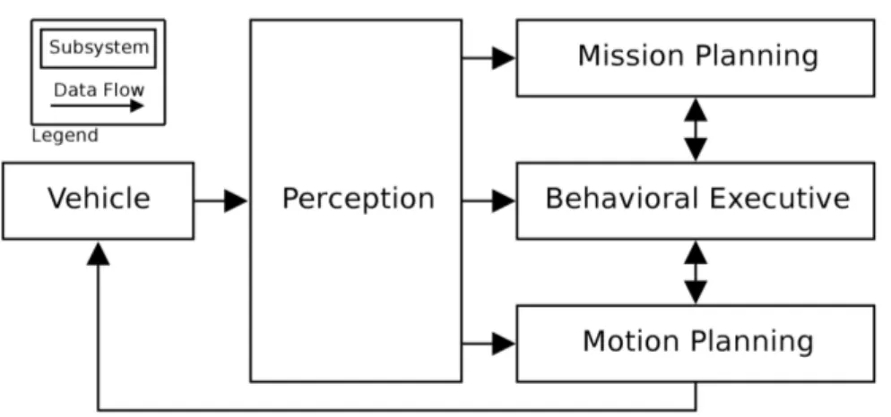
Boss [10] The software system that controls Boss, the Carnegie Mellon University vehicle, is divided into four primary subsystems: Perception, Mission Planning, Behavioral Executive, and Motion Planning. Their dominant communication paths are shown in Figure 1.8, and they use a message-passing protocol according to the anonymous publish-subscribe [63] pattern. The Perception subsystem processes sensor data from the vehicle and produces a collection of semantically-rich data elements such as the current pose of the robot, the geometry of the road network, and the location and nature of various obstacles such as roadblocks and other vehicles. The Mission Planning subsystem computes the fastest route to reach the next checkpoint from any point in the road network; it publishes a Value Function that maps each waypoint in the road network to the estimated time to reach the next checkpoint. The Behavioral Executive follows the Value Function from the robot’s current position, generating a sequence of incremental Motion Goals for the Motion Planning subsystem to execute. The Motion Planning subsystem is responsible for the safe, timely execution of the incremental goals issued by the Behavioral Executive; it publishes its progress on the current goal, used by the Behavioral Executive to cue the selection and publication of subsequent or alternate goals as appropriate.
Junior [77] Junior’s software architecture is designed as a data driven pipeline in which individual modules process information asynchronously; each module communicates with other modules via an anonymous publish/-subscribe message passing protocol as for Boss. The software is roughly organized into five groups of modules (shown in Figure 1.9):
Figure 1.8: Boss’ software architecture.
individual sensors, and make resulting sensor data available to the rest of the software modules;
• Perception modules segment the environment data into moving vehicles and static obstacles. They also provide precise localization of the vehicle relative to the digital map of the environment;
• Navigation modules determine the behavior of the vehicle. The navigation group consists of a number of motion planners, plus a hierarchical finite state machine for invoking different robot behaviors and preventing deadlocks;
• Drive-by-wire interface controls the vehicle by passing back com-mands through the drive-by-wire interface. This module enables software control of throttle, brake, steering, gear shifting, turn sig-nals, and emergency brake;
• Global services are a number of system level modules provide logging, time stamping, message passing support, and watchdog functions to keep the software running reliably.
As we can see, in literature there exists different kind of architectures, less or more complex, that share a common base and cyclical schema represented by a first part of perception of the environment, followed by a planning phase and then a stage where the robot carries out the actions previously planned.
Figure 1.9: Junior’s software architecture.
Taking the cue from these examples we decided to implement our own architecture based on the Sense-Plan-Act paradigm. In the next chapter we present a general overview of the designed architecture, while in the following chapters we focus the attention specifically on each module.
a chapter for each main component: simulation (Chapter 3), localization (Chapter4) and Model Predictive Control (Chapter5). The aim of this chapter is to give a general overview of the architecture and how the communication between all its components is implemented.
2.1
Relevant background
Writing software for robotics purposes is challenging because different types of robot can have extremely diverse hardware, making code reuse hardly possible. Moreover, the modules developed must implement a deep stack starting from driver-level software up to high-level functionalities, like autonomous driving, reasoning or localization. In order to resolve these issues, during the years, various frameworks have been developed often aiming at a very specific purpose. This caused a fragmentation in the robotic software systems used in industry and academia. ROS is an attempt to create a general framework that promotes modularity and code reuse, and it became the de facto standard for robot software.
The Robot Operating System (ROS), developed by the Stanford Artifi-cial Intelligence Laboratory and by Willow Garage, is a flexible framework for writing robot software. It is a collection of tools, libraries and conven-tions that aim to simplify the task of creating complex and robust robot behaviors across a wide variety of robotic platforms.
Creating truly robust, general-purpose robot software is hard. From the robot’s perspective, problems that seem trivial to humans often vary wildly between instances of tasks and environments. Dealing with these
variations is so hard that no single individual, laboratory, or institution can hope to do it on its own. As a result, ROS was built from the ground up to encourage collaborative robotics software development. For example, one laboratory might have experts in mapping indoor environments, and could contribute a world-class system for producing maps. Another group might have experts at using maps to navigate, and yet another group might have discovered a computer vision approach that works well for recognizing small objects in clutter. ROS was designed specifically for groups like these to collaborate and build upon each other’s work. [4]
ROS was designed to be as distributed and modular as possible, so that you can pick and choose which parts are useful for you and which parts you’d rather implement yourself. The distributed nature of ROS also fosters a large community of user-contributed packages that add a lot of value on top of the core ROS system. At last count there were over 3,000 packages in the ROS ecosystem, and that is only the ROS packages that people have taken the time to announce to the public. These packages range in fidelity, covering everything from proof-of-concept implementations of new algorithms to industrial-quality drivers and capabilities. The ROS user community builds on top of a common infrastructure to provide an integration point that offers access to hardware drivers, generic robot capabilities, development tools, useful external libraries, and more.
Over the past several years, ROS has grown to include a large com-munity of users worldwide. Historically, the majority of the users were in research labs, but increasingly we are seeing adoption in the commercial sector, particularly in industrial and service robotics. The ROS community is very active. According to our metrics, at the time of writing, the ROS community has over 1,500 participants on the ROS-users mailing list, more than 3,300 users on the collaborative documentation wiki, and some 5,700 users on the community-driven ROS Answers Q&A website. The wiki has more than 22,000 wiki pages and over 30 wiki page edits per day. The Q&A website has 13,000 questions asked to date, with a 70% percent answer rate. [78] Figure 2.1 shows how the ROS vibrant community is spread all over the world.
A typical ROS system consists of a number of processes, called nodes, potentially on a number of different hosts, connected at runtime in a peer-to-peer topology. Each node is an independent unit that performs computation, usually associated with a specific functionality or hardware component. Nodes are organized in packages, which are directories that contain an XML file describing the package and stating any dependency. In order to increase the flexibility and portability of the system, it is possible to implement nodes using four different languages: C++, Python, Octave
Figure 2.1: The costantly growing ROS vibrant community.
and LISP. Modules implemented with different languages can coexist in the same system, therefore it possible to use different tools for specific needs, e.g., fast prototyping and implementation of simpler node using Python with core functionalities implemented with C++. This is possible because the specification of ROS is at the messaging layer.
Messages defined with a simple, language-neutral Interface Definition Language (IDL) allow the communication between nodes. The IDL uses short text files to describe fields of each message, and allows composition of messages. Code generators for each supported language then generate native implementations, which are automatically serialized and deserialized by ROS as messages are sent and received. The ROS-based codebase contains hundreds of types of messages, which transport data ranging from sensor feeds to objects and maps, moreover it is possible to define custom messages for any specific need.
A node sends a message by publishing it to a given topic, which is identified by its name. A node that is interested in a certain kind of data subscribes to the appropriate topic. Multiple concurrent node can publish or subscribe on a single topic, and each node can interact with multiple topic. In general, publishers and subscribers are not aware of each other existence.
In order to complement the asynchronous communication system real-ized by the topic-based publish-subscribe model (Figure2.2), ROS provides a synchronous system, called services. Each service is defined by a string name and a pair of strictly typed messages: one for the request and one for the response. Unlike topics, only one node can advertise a service of any particular name.
Figure 2.2: The Publisher/Subscriber protocol.
allow processes to find each other at runtime. The master has this role, it enables individual ROS nodes to locate each other. Once these nodes have located each other, they communicate using peer-to-peer channels. Moreover, the master provides a parameter server, which is a shared, multi-variate dictionary that is accessible via network APIs. Nodes use this server to store and retrieve parameters at runtime. Figure 2.3 shows the performed steps to set up the communication.
Figure 2.3: Set up of the ROS communications.
Along with the meta-operating system, the ROS environment provides various tools. These tools perform various tasks: for example navigate the source code tree, get and set configuration parameters, visualize the peer-to-peer connection topology, run collection of nodes, monitor the behavior of topics, graphically plot message data and more. Some of these tools
Figure 2.4: A typical rviz window.
have simple functionalities, e.g., showing all the messages published on a topic, while others are more complex. For example, rviz [27] (Figure2.4) is a complete visualization tool that shows in real time, in a 3D environment, data streamed on the topics. Another example is rosbag, which records and plays back to ROS topics.
2.2
Architectural overview
In order to develop a flexible and modular architecture and to take ad-vantage of some existing simulators, we decided to use ROS, which is up to now considered the standard de-facto for robot applications. Different reasons led us to this choice: first of all the possibility to design and develop different independent modules to handle all the single parts of the architecture. This allows us to test and debug separately all the system functionalities and to add on demand the modules we need. In addition, the open source logic adopted by ROS allows the developers to share their works in a official repository. This appeared to be useful for our work since we reused some of them. Another reason that drove our choice was the integration with simulators. Since simulation is one of the main phases of a robot development, we needed a system able to easily interfacing with one of them.
The software architecture can be divided into three main parts: the vehicle (Chapter 3), the localization (Chapter4) and the Model Predictive
Figure 2.5: General software architecture.
Control (Chapter 5). More specifically this division can be seen as what has to run in the vehicle and the vehicle itself. Therefore the first part, localization and MPC modules, is independent from the second one, vehicle simulator, since it works regardless of the associated platform. Regarding the vehicle simulation it is possible to define three simulation profiles:
• ideal simulation: the vehicle is described as a single-track model (Section 3.3.1) and a ROS node has been developed to simulate its behavior based on odeint. Localization is provided by the simulation itself;
• Gazebo simulation: the ideal simulator is substituted by Gazebo (Section 3.3.2) and the localization is performed using the position
provided by the simulator itself;
• Gazebo simulation with ROAMFREE: the simulation is per-formed by Gazebo while the localization is estimated by ROAMFREE library (Section 4.1).
In Figure2.5it is possible to see an high level representation of the control architecture with the three profiles. We decided to put the localization
Figure 2.6: Sense-Plan-Act paradigm.
module performed with ROAMFREE in the left half of the schema since this module is independent from the vehicle and it has to run close to the MPC.
2.2.1
Main modules
In order to describe the main modules of the architecture, we followed the hierarchical paradigm Sense-Plan-Act (Figure2.6) [62].
1. Sense - the robot needs the ability to sense important things about its environment, like the presence of obstacles or navigation aids; 2. Plan - the robot needs to take the sensed data and figure out how
to respond appropriately to it, based on a preexisting strategy; 3. Act - finally, the robot must actually act to carry out the actions
that the plan calls for.
The core part of the sense module consists in the localization node (Chapter 4), which is based on ROAMFREE. This framework provides pose tracking combining the information coming from an arbitrary number of sensors. In the current configuration the localization module estimates the robot poses exploiting a GPS, a magnetometer and an Inertial Mea-surement Unit, which includes both a gyroscope and an accelerometer. Since ROAMFREE provides vehicle position and orientation and since for the planning module we needed also information about the sideslip angle of the vehicle, to complete the perception part we implemented a sideslip angle estimator (Section 5.5).
The planning part of the architecture is represented by the MPC node (Chapter5). As its name suggests, this node implements a Model Predictive Control. The goal to reach is given through a configuration file which is
read when the node is launched. It cyclically reads the current position of the vehicle and elaborates the commands to be sent to the actuators.
The act section can be represented by the simulators. For the ideal one it is the integration of the differential equations that describe the single-track model (Section 3.3.1) which represent the vehicle. About Gazebo it is the plugin developed to control the gas pedal and steer (Section 3.4.4).
2.2.2
ROS topics and messages
For the development of the architecture, even though ROS provides different types of messages, it has been necessary to create several custom messages to satisfy our needs. Here we provide a list of them specifying the contest in which they are used:
• vehicle_state: it includes information about the position of the vehicle, i.e., the Cartesian coordinates, the sideslip angle, the yaw angle and its rate (Section 3.3.1);
• mpc_velocity: it includes the output of the MPC controller, i.e., the value of the velocity over x-axis and the value of the velocity over y-axis (Section 5.2);
• speed_steer: it includes the values of the desired velocity and steering angle to be assigned to the vehicle (Section 5.3);
• pointP: this message includes the vehicle current state plus the Cartesian coordinates of the vehicles plus the Cartesian coordinates of the relative linearization (Section5.3).
The values used in these messages are described as float64, that is the ROS representation of the C++ double [56]. Furthermore, regarding the message types offered by ROS we used the std_msgs::Float64 to send single information about the yaw angle, the yaw rate and the sideslip angle. In Figure 2.7it is possible to see in detail the composition of the custom messages.
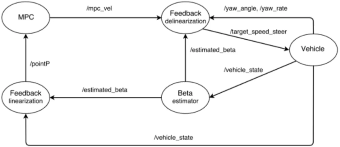
The ROS topics used within the project, shown in Figure 2.8, are the following:
• /vehicle_state: it is used to publish the current state of the vehicle; • /mpc_vel: this topic is used by the node MPC to publish its own
Figure 2.7: Custom messages.
• /target_speed_steer: on this topic the node Feedback delineariza-tion publishes the resulting velocity and steering angle;
• /estimated_beta: on this topic it is possible to read the value of the estimated sideslip angle;
• /yaw_angle: topic on which it is possible to read information about the yaw angle of the vehicle;
• /yaw_rate: topic on which it is possible to read information about the yaw rate of the vehicle, i.e., the angular velocity with respect to the z-axis;
• /pointP: on this topic it is published the result of the feedback linearization.
While integrating Gazebo, it has been necessary to change the topic structure to take advantage of the preexisting simulator API. In fact there were already some topics on which to publish messages to control the vehicle:
• /polaris/gas_pedal: topic used to send command for the gas pedal;
• /polaris/brake_pedal: topic used to control the brake pedal; • /polaris/hand_wheel: topic used to set the value of the hand
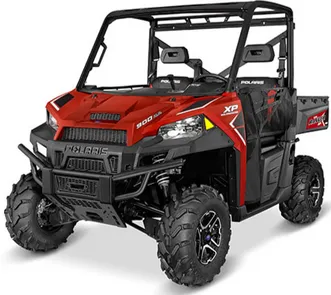
In this chapter we present the reference vehicle, the used sensors and their simulations. For our work we decided to adopt as vehicle the “Polaris
Ranger XP 900” (Figure3.1) [54]. Our choice was driven by the fact this platform has been recently used in the DARPA Robotics Challenge in 2015 [19] where one of the 8 tasks to be performed by the humanoid robots was to drive a Polaris Ranger XP 900 EPS” to a specified location. Thanks to this, a model of this vehicle was already implemented in the repository of the chosen simulation environment and we could take advantage of it.
In the relevant background we describe some works related to the same vehicle category and we give an overview of the main robotics simulation environments with a special focus on the chosen one. Among the implemented simulation profiles, we used also a mathematical model described by differential equations. The integration of these equations, needed to simulate the vehicle behavior, requires the usage of a library able to solve ordinary differential equations. For this reason we describe the used library and afterwards how it has been implemented.
3.1
Relevant background
3.1.1
Related works
Some similar projects on automated road shuttles, like golf cars and mini-buses, have already been developed. This type of vehicle typically operates at lower speeds in pedestrian environments and serves as a form of public transit.
Figure 3.1: Polaris Ranger XP 900 EPS.
Auro
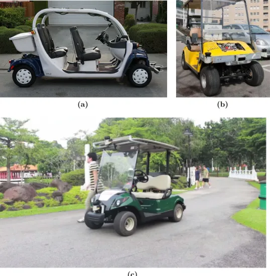
The startup Auro says its self-driving golf cart (Figure 3.2a) will lead to autonomous shuttles for theme parks, vacation resorts, and retirement communities. The current prototypes are golf carts modified with laser scanners, radar, cameras, GPS, computers, and other components needed to actuate the golf cart actuators. Auro Robotics company is focused on the more modest goal of ferrying people on autonomous vehicle around the private grounds of universities, retirement communities, and resorts. Auro’s vehicles require a detailed 3-D map of the environment where they operate, and collecting that data for a private campus and keeping it up-to-date is easier. Such environments are also less physically complex, have lower speed limits, and present fewer complicated traffic situations [66].
USAD
The Urban Shuttles Autonomously Driven (USAD) project (IRAlab, Univ. Milano - Bicocca in cooperation with Politecnico di Milano) aims at the development of vehicles capable to drive autonomously in a urban setting [76]. The specific aspects of the robotic research involved, w.r.t. extra-urban autonomous driving, is the need to localize the vehicle, despite the absence of the GPS signal and/or its not-good-enough accuracy, which implies a research focus on the perception side of the navigation. The
(a) (b)
(c)
Figure 3.2: Some examples of self-driving projects involving golf cars: Auro(a),
vehicle is equipped with a GPS, two high-definition cameras to detect road markings, two single plane laser scanners installed in the front edges of the vehicle, and a third laser scanner in a central position with less field of view but able to detect four planes (Figure3.2b).
SMART
The Singapore-MIT Alliance for Research and Technology (SMART) de-signed a fleet of autonomous golf cars (Figure 3.2c) which were demon-strated in public trials in Singapore’s Chinese and Japanese Gardens, for the purpose of raising public awareness and gaining user acceptance of autonomous vehicles. The golf cars were designed to be robust, reliable, and safe, while operating under prolonged periods of time. The overall system design foresees that any member of the public has to not only be able to easily use the system, but also not to have the option to use the system in an unintended manner.
A Yamaha YDREX3 electric golf car was used as vehicle base platform and retrofitted by the SMART team to incorporate necessary actuation, sensing, computing, and power systems along with various additional features to enhance passengers’ comfort and safety. Two non-contact magnetic encoders are mounted to the rear axle of the golf car, one on each side of the drive shaft. A MicroStrain 3DM-GX3-25 Inertial Measurement Unit (IMU) is rigidly mounted to the chassis above the center of the rear axle to provide attitude and heading of the vehicle. The encoder and the IMU readings are combined to provide vehicle’s odometry information in 6 degrees-of-freedom. Environmental sensing is achieved through several 2D LIDARs and a webcam. One SICK LMS 151 LIDAR is mounted facing downward in the front of the vehicle roof, where the data returned is fused with odometry readings to achieve localization as described in [23]. A second SICK LMS 151 is mounted horizontally in the lower front of the vehicle for obstacle detection. Two SICK TiM551 LIDARs are mounted at the rear corners of the golf car to provide all around obstacle detection [51].
3.1.2
Physical simulation of vehicles
A robotics simulator is used to create embedded robotics applications without depending physically on the actual machine, thus saving cost and time.
When working with an autonomous vehicle, the role of the simulator is fundamental. The robot characteristics, the typical operating environment