Autore:
Daniele Migliorini
Relatori:
Prof. Luciano Lenzini Ing. Giovanni Stea
Resource Allocation in LTE Advanced for
QoS and Energy Efficiency
Anno 2012
UNIVERSITÀ DI PISA
Scuola di Dottorato in Ingegneria “Leonardo da Vinci”
Corso di Dottorato di Ricerca in
Ingegneria dell’informazione
A Veronica
Ai miei genitori
Abstract:
Long Term Evolution (LTE) and LTE-Advanced (LTE-A) are establishing themselves as the new standard of 4G cellular networks in Europe and in several other parts of the world. Their success will largely depend on their ability to support Quality of Service for different types of users, at reasonable costs. The quality of service will depend on how effectively the cell bandwidth is shared among the users. The cost will depend – among many other factors – on how effectively we exploit the cell capacity. Being able to exploit bandwidth efficiently postpones the time when network upgrades are required. On the other hand, operation costs also depend on the energy efficiency of the cellular network, which should avoid wasting power when few users are connected.
As for bandwidth efficiency, the recent LTE/LTE-A standards introduced MIMO (Multiple Input Multiple Output) transmission modes, which allow both reliability and efficiency to be increased. MIMO can increase the throughput significantly. In a MIMO system, the selection of the MIMO transmission modes (whether Transmission Diversity, Spatial Multiplexing, or Multi-User MIMO) plays a key feature in determining the achievable rate and the error probability experienced by the users. MIMO-unaware scheduling policies, which neglect the transmission mode selection problem, do not perform well under MIMO. In the current literature, few MIMO-aware LTE-A scheduling policies have been designed. However, despite being proposed for LTE-A, these solutions do not take into account some constraints inherent to LTE-A, hence leading to unfeasible allocations. In this work, we propose a new framework for Transmission Mode Selection and Frequency-Domain Packet Scheduling, which is compliant with the constraints of the LTE-A standard. The resource allocation framework accommodates real-time requirements and fairness on demand, while the bulk of the resources are allocated in an opportunistic fashion, i.e. so as to maximize the cell throughput. Our results show that our proposal provides real-time connections with the desired level of QoS, without utterly sacrificing the cell throughput.
As far as energy efficiency is concerned, we studied the problem of minimizing the RF power used by the eNodeB, while maintaining the same level of service for the users. We devised a provisioning framework that exploits the Multicast/Broadcast over a Single Frequency Network (MBSFN) mechanism to deactivate the eNodeB on some Transmission Time Intervals (TTI), and computes the minimum-power activation required for guaranteeing a given level of service. Our results show that the provisioning framework is stable, and that it allows significant savings with respect to an always-on policy, with marginal impact on the latency experienced by the users.
Sommario:
Long Term Evolution (LTE) e LTE-Advanced (LTE-A) si stanno affermando come il nuovo standard delle reti cellulari di quarta generazione. Il successo di queste tecnologie dipenderà, in larga parte dalla loro capacità di offrire qualità del servizio a differenti tipi di utenti a costi ragionevoli. La qualità del servizio dipende da come effettivamente viene suddivisa la banda tra gli utenti. Il costo dipende –tra molti altri fattori- da come effettivamente si sfrutta la capacità di cella. Riuscire a sfruttare la banda in maniera efficiente rimanda il momento in cui è necessario un upgrade dell’infrastruttura di rete. D’altra parte, i costi dipendono anche dall’efficienza energetica della rete cellulare che dovrebbe evitare sprechi di energia quando ci sono pochi utenti connessi.
Riguardo all’efficienza di banda, le recenti versioni degli standard LTE/LTE-A introducono il concetto di modo trasmissivo ad antenne multiple (MIMO) che permette di incrementare sia l’affidabilità della trasmissione sia l’efficienza. Queste tecniche incrementano il throughput in maniera significativa. In un sistema MIMO la selezione del modo trasmissivo (tra i cui Transmission Diversity, Spatial Multiplexing, o Multi-User MIMO) svolge una funzione chiave nel determinare il throughput e la probabilità di errore sperimentate dall’utente finale. Gli scheduler che non tengono in considerazione le tecniche MIMO (MIMO-unware) e il problema della selezione del corretto modo trasmissivo non offrono buone prestazioni perché non sfruttano tale diversità. In letteratura sono presenti pochi lavori dove si propongono algoritmi di scheduling MIMO-aware. Tuttavia nonostante questi lavori siano proposti per LTE-A non tengono però in considerazione alcuni importanti vincoli presenti nello standard che portano ad allocazioni di risorse non applicabili ad LTE-A. In questa tesi si propone una nuova framework per la selezione della modalità trasmissiva MIMO e un algoritmo di scheduling nel dominio della frequenza compatibile con i vincoli dello standard LTE-A. Questa framework gestisce traffici real-time e fairness su domanda mentre il resto delle risorse sono allocate in maniera prettamente opportunistica massimizzando così il throughput di cella. I risultati mostrano che la nostra proposta offre, ai traffici real-time, il livello desiderato di qualità del servizio senza sacrificare troppo il throughput di cella.
Per quanto riguarda l’efficienza energetica, abbiamo affrontato il problema di minimizzare la potenza RF usata dalla cella mantenendo lo stesso livello di servizio agli utenti. Abbiamo messo a punto una framework di provisioning che sfrutta il meccanismo Multicast/Broadcast over a Single Frequency Network (MBSFN) per disattivare la cella in alcuni Transmission Time Intervals (TTI) e calcola le attivazioni a potenza minima richieste per garantire un certo livello di servizio. I risultati mostrano che la framework di provisioning è stabile e offre un significativo risparmio con un impatto marginale sulla latenza sperimentata dagli utenti.
Contents ... 9
LIST OF FIGUREs ... 11
LIST OF TABLEs ... 13
1 INTRODUCTION ... 15
2 LTE Technology ... 18
2.1
3gpp Releases ... 18
2.1.1
Improvements ... 19
2.1.2
System architecture ... 20
2.1.3
Protocols ... 22
2.1.4
LTE Advanced ... 23
2.1.5
Physical Layer Details ... 24
2.1.5.1
Access schemes ... 24
2.1.5.2
MIMO modes in LTE ... 26
3 Proposed Scheduler ... 29
3.1
Introduction ... 29
3.2
LTE-‐A Resource allocation and constraints ... 29
3.3
System Model and Throughput-‐Optimal Scheduling Problem ... 31
3.4
Polynomial-‐time Opportunistic Scheduling ... 36
3.4.1
TMS algorithms ... 37
3.4.2
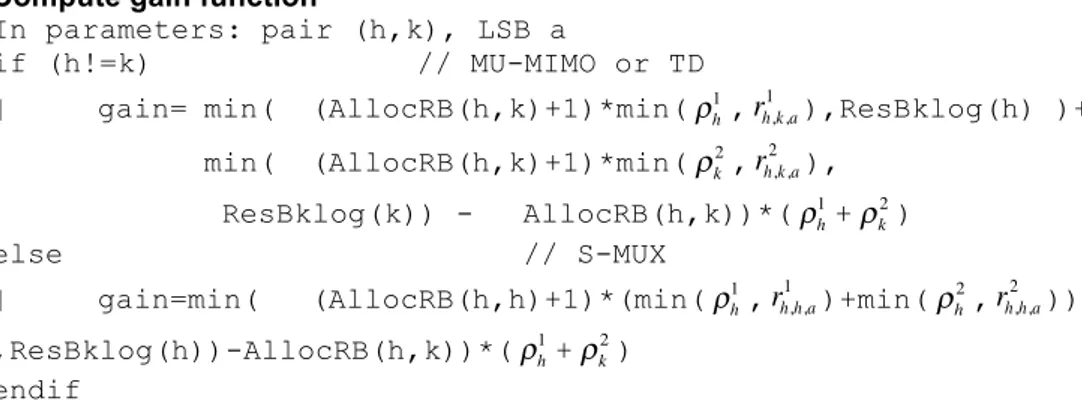
Allocation function ... 39
3.5
QoS and Fairness Constraints ... 42
3.5.1
QoS Step ... 43
3.5.2
Fairness Step ... 45
3.5.3
Efficiency Step ... 46
3.6
Performance evaluation ... 47
3.6.1
Simulator ... 47
3.6.1.1
OMNeT++ ... 47
3.6.1.2
LTE OMNeT++ Embodiment ... 47
3.6.2
Schedulers ... 48
3.6.3
Traffic ... 49
3.6.4
Metrics ... 50
3.6.5
System Model ... 51
3.6.6
Results ... 52
3.6.6.1
QoSMuMIMO Tuning ... 52
3.6.6.2
Comparison with other scheduler ... 57
3.7
Related Work ... 62
4 Energy Aware provisioner ... 64
4.1
Introduction ... 64
4.2
MBSFN patterns in LTE-‐Advanced ... 64
4.3
System model and problem formulation ... 65
4.4
Approximating the optimal solution for known traffic demands ... 67
4.4.1
Throughput-‐oriented heuristic ... 69
4.4.2
Predicting the traffic demand ... 73
4.4.3
Distributing RBs among active frames ... 74
4.5
Making decisions on a per-‐TTI basis ... 75
4.6
Results ... 77
4.6.1
Simulated scenarios ... 77
5 Conclusions ... 82
Figure 2-1 3GPP Groups ... 18
Figure 2-2 3GPP Long Term Evolution overview ... 19
Figure 2-3: LTE Evolved Packet System ... 21
Figure 2-4: LTE Protocol Stack ... 22
Figure 2-5: OFDMA ... 25
Figure 2-6: SC-FDMA ... 25
Figure 2-7: LTE frame structure ... 26
Figure 3-1: the Rate Matrix ... 32
Figure 3-2: Mathematical model for the MTAP ... 35
Figure 3-3: The resource allocation framework ... 36
Figure 3-4: K-max algorithm pseudo-code ... 38
Figure 3-5: Pseudo-code of MaxGain algorithm ... 41
Figure 3-6: The enhanced allocation function ... 42
Figure 3-7: Tagger function pseudo code ... 43
Figure 3-8: Selector function pseudo code ... 44
Figure 3-9: Fairness step pseudo code ... 46
Figure 3-10: Average MOS of UE with different fairness settings ... 54
Figure 3-11: Average delay of gaming traffic with different fairness settings ... 54
Figure 3-12: Average delay of Video on Demand traffic with different fairness settings ... 55
Figure 3-13: Average Throughput of full buffer UE with different fairness settings 56
Figure 3-14: Transmission mode usage ... 57
Figure 3-15: Cell throughput with different scheduler ... 57
Figure 3-16: Average Full buffer traffic throughput with different scheduler ... 58
Figure 3-17: Average MOS of Voice over IP traffic with different scheduler ... 59
Figure 3-18: Average delay of gaming traffic with different scheduler ... 60
Figure 3-19: Average delay of Video on Demand traffic with different scheduler ... 60
Figure 3-20: Average delay of Video on Demand traffic with different scheduler (rescaled) ... 61
Figure 4-1: LTE-A – Allowed MBSFN subframes ... 65
Figure 4-2: Power model ... 66
Figure 4-3: Pseudo-code for the throughput-oriented heuristic ... 72
Figure 4-4. Pseudo-code for the dynamic algorithm ... 76
Figure 4-5 Depleted power with increasing network load ... 78
Figure 4-6 Average delay with increasing network load ... 79
Figure 4-7 Cell Throughput with 2 MB/s of network load ... 80
Figure 4-8 Depleted power with increasing activation time of the provisioner ... 80
Figure 4-9 Average delay with increasing activation time of the provisioner ... 81
LIST OF TABLES
Table 1-1: LTE versus LTE Advanced ... 23
Table 2-1: Number of bits per CQI ... 33
Table 2-2: Configuration of traffic models ... 50
Table 2-3: System model parameters ... 51
Table 2-4: Simulated scenario ... 52
Table 2-5: Urgency settings for each traffic class ... 53
Table 2-6: Fairness step settings ... 53
1 INTRODUCTION
The Long Term Evolution (LTE) of the Universal Mobile Telecommunication System (UMTS) [14]is gaining progressive hold as an access network for Internet services, thanks for its foreseen near-ubiquitous coverage and high bandwidth. At the moment of writing, the first experimental setups of LTE networks are being deployed all over Europe, including Italy. LTE promises higher bandwidth (up to 300 Mbps in the downlink and 75 in the uplink), which makes this technology suitable for ubiquitous Internet access (besides for supporting voice). Due to its coverage, regulated access and security, LTE is also a serious candidate for serving as an infrastructure for machine to machine (M2M) communications. In the near future, in fact, intelligent devices will be endowed with communication capabilities, to improve the quality of living in everyday life. Examples of such communications are those arising from smart grids, i.e. electrical power grids provided with the intelligence to coordinate a distributed power supply, serving appliances which can schedule their jobs based on price and power availability. All this intelligence requires diffused, wide-scale communication capabilities. Another example is vehicular communications, where single vehicles communicate with a central infrastructure to reduce road dangers, accidents and congestion.
Traffics generated by all the above applications need to coexist on a single infrastructure. Therefore, LTE networks need to be provided with quality of service (QoS), i.e., the ability to give different treatment to traffic of different applications. LTE has native QoS differentiation support. Traffic is classified into four traffic classes, namely Conversational, Interactive, Streaming, Background, whose packet can be treated differently. Although the LTE network is composed by many blocks (i.e., a wired part and a wireless interface), the part where algorithms for QoS differentiation are mostly required is the wireless one, i.e. the e-UTRAN interface in a network cell. In the latter, a central base station or eNodeB shares radio resources among a number of User Equipments (UEs), i.e. handheld devices, laptops or home gateways, using Orthogonal Frequency Division Multiplexing Access (OFDMA) in the downlink. From a logical standpoint, on each Transmission Time Interval (TTI, 1ms), the eNodeB allocates a time/frequency frame of resource blocks (RBs) to the UEs. RBs carry a variable number of bits to an UE, depending on the transport block size (TBS) selected by the eNodeB. The latter is chosen based on the Channel Quality Indicator (CQI) advertised by the UE. The scheduling algorithm at the eNode-B, therefore, plays a crucial role into QoS differentiation. The latter should be able to pick those UEs whose channel quality is the highest, so as to exploit the cell bandwidth efficiently, something which is called opportunism. On the other hand, since the channel quality may depend on physical details of the receiver and, mostly, on the distance between the eNodeB and the UE, and on the interference generated by nearby cells (which is also location-dependent), only pursuing opportunism as a resource allocation criterion may lead to gross unfairness, where some UEs are starved whereas others hog the whole channel bandwidth. Therefore, opportunism has to be balanced with fairness. Moreover, packets with deadline constraints (e.g., voice, gaming, video) should be transmitted by their deadline, with a comparatively minor attention to opportunism. Striking a good balance between deadlines, fairness and opportunism is already tough enough per se. A last comment, though by no means the least concern, is
related to complexity. Schedules must be built in a TTI time, and may include hundreds of UEs. Therefore, non-polynomial algorithms are out of the picture, and relatively simple polynomial ones should be preferred.
In the endless race for capacity of cellular systems, Multiple-Input Multiple-Output (MIMO) transmissions have been introduced. LTE (Release 8) allows MIMO in the downlink direction, whereas the more recent Release 10, which goes by the commercial name of LTE-Advanced (LTE-A), allows it for both the downlink and the uplink. MIMO transmissions exploit spatial diversity to send more than one stream to a user, or a pair thereof, on the same RB. Three MIMO transmission modes are possible: transmit diversity (TD), where (with reference to the downlink direction) the same codeword is sent twice to the UE, thus increasing the likelihood of correct decoding and, indirectly, allowing higher-order modulations (e.g. 64QAM) to be exploited; spatial multiplexing (S-MUX), where two different codewords are sent to the same UE, thus doubling its rate; multi-user MIMO (MU-MIMO), where two spatially separated UEs are coupled on the same RB. TD and S-MUX are called single-user MIMO (SU-MIMO) modes. LTE-A allows an eNodeB to decide which MIMO mode to use for a given UE (or pair thereof) dynamically, on a per-TTI basis.
It is a fact that MIMO transmissions increase the cell capacity. However, resource scheduling under MIMO is considerably more involved. In fact, besides deciding which RB goes to whom, a transmission mode has to be selected for each UE (or pair thereof). Transmission mode selection plays a role on how many bits you can fit into an RB, hence transmission mode selection and frequency-domain packet scheduling (i.e., RB allocation) are not independent.
As a first contribution of this thesis, we investigate resource allocation in the downlink of a MIMO-capable LTE-A system. Our purpose is to provide a scheduling framework which accommodates different types of traffic, and exploits radio resources efficiently. We first show that computing the maximum throughput allocation in a MIMO-enabled LTE cell is practically unfeasible given the number of UEs involved and the scheduling timescale. Hence, we propose to separate the resource allocation problem into two sub-problems, namely transmission mode selection (TMS) and frequency-domain packet scheduling (FDPS). For the TMS problem, we propose a tunable polynomial-time algorithm. For the FPDS sub-problem, we propose a modular framework that allows different types of services to be accommodated on demand. The basic block is an opportunistic allocation, which maximizes the throughput. Other blocks can be added if traffics with fairness (i.e., minimum throughput) or QoS (i.e., deadline) constraints are to be considered. We show via simulation that the opportunistic version of the FPDS achieves near-optimal cell throughput, and that adding QoS and fairness only entails a modest throughput loss. To the best of our knowledge, no previous work covers multi-service scheduling under MIMO constraints. Those which consider single aspects (e.g., only throughput maximization, or fairness, under MU-MIMO) often rely on simplifications and idealizations that make them unsuitable for the LTE-A environment. Some either ignore MU-MIMO (e.g. 16), or assume arbitrary, out-of-standard MU-MIMO UE pairings in the same TTI (e.g. 17), others neglect the TMS problem (which greatly influences the cell throughput) by forcing a priori a single transmission mode (e.g. [40][41]).
As a second contribution of this thesis, we study the energy efficiency of resource allocation in the above settings. There has been a growing interest in the energy
consumption aspects of computer networks in the last years. In the cellular network environment, this has been largely motivated by the operators’ need to cut the energy bill in order to save on the operational costs. It is a fact that cellular networks (and others beside it) are dimensioned for peak demand, and are underutilized in off-peak hours (e.g., at night). LTE’s flexible, millisecond-based frame structure makes it possible to selectively deactivate transmissions on some TTIs at times of low load without utterly sacrificing responsiveness. The discontinuous transmission (DTX) mechanism allows the eNodeB to communicate to its associated UEs a pattern of future activations (e.g., a 40ms superframe), marking some frames as inactive. During these, the eNodeB will be switched off and no communication will take place. To complicate the scenario, there are frames where UEs are supposed to receive pilot signals (e.g., synchronization, paging, etc.), hence not all the frames can be switched off. Furthermore, due to the fact that OFDMA symbols are reserved for pilot signals, the number of OFDMA symbols which are available for UE transmission, i.e. the frame capacity, varies among frames.
The second contribution of this thesis is a provisioning algorithm that computes a frame activation pattern in a superframe, so as to carry an expected load at the minimum power. The provisioning algorithm relates to the scheduler, which is activated only during on frames. Depending on the bandwidth efficiency of the scheduler, the energy efficiency will vary as well. We present the minimum-power allocation as an optimization problem, and we propose an algorithm that finds a good suboptimal solution given the load. The provisioning algorithm is tested in conjunction related to the MIMO scheduler, and proved to be stable. Furthermore, we show that the energy saving is indeed significant.
There has been scant little work on DTX so far. The EARTH project of the EU 6th Framework Programme has dealt with the issue, but its publications are appearing as we write down the thesis, and only preliminary studies are available [41], for instance, shows the saving potentials for metropolitan areas, but does not present any algorithm.
This thesis is organized as follows: In chapter 2 we describe the LTE technology, the proposed MIMO-aware scheduler is presented in chapter 3 and evaluated in section 3.6. In chapter 4 we presents the energy aware provisioner while in section 4.6 we show the results of this algorithm. Conclusion are drawn in chapter 5.
2 LTE TECHNOLOGY
In this chapter we briefly introduce the Long Term Evolution (LTE) technology, pointing out the motivations that lead to its development, its base characteristics and the future evolutions. Then we provide some details on the physical layer, considering in particular the Multiple Input Multiple Output (MIMO) transmission modes used within LTE, which are one of the key topics of the present work.
2.1 3gpp Releases
In recent years the number of mobile subscribers has increased tremendously and voice communication has become mobile in a massive way. At the same time data usage has grown fast and mobile devices are now used for a wide range of other applications like web browsing, video streaming and online gaming. Beside cell phones, also notebooks, personal digital assistants and other hand-held devices are now part of the mobile environment, leading to a heterogeneous population of User Equipment (UEs) with different needs.
Within such a scenario, the demand for an ubiquitous and broadband Internet access is constantly increasing, and mobile communication systems have to provide evolved technologies to support both voice and data traffic.
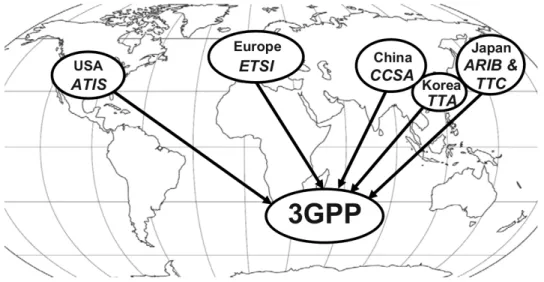
The Third Generation Partnership Project (3GPP) [1] is a collaboration among international groups of telecommunication associations, founded to define globally
applicable standards for next-generation mobile networks ( Figure 2-1).
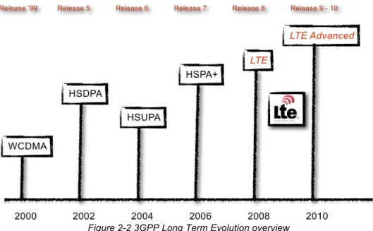
Established in 1998, the 3GPP has developed several standards, named releases, to support the increasing needs of mobile communications (Figure 2-2).
Figure 2-1 3GPP Groups
Among these releases, LTE [2] represents a major step towards the support of heterogeneous traffics and different kind of UEs. Based on LTE, LTE Advanced [3]
is the further step of the 3GPP Release standardization process to meet the requirements imposed by the International Telecommunication Union (ITU) [4] for fourth-generation (4G) networks.
Here both LTE and LTE Advanced are briefly described. First we consider the improvements introduced by LTE with respect to legacy 3GPP releases. Then we present the system architecture and the protocol stack. Finally we underline the enhancements introduced by LTE Advanced.
Figure 2-2 3GPP Long Term Evolution overview
2.1.1 Improvements
The first LTE release has been developed as the natural evolution of High Speed Packet Access (HSPA) in order to ensure the competitive- ness of third-generation (3G) technologies for the next years. To reach this objective, LTE introduces several improvements with respect to the previous releases. Such improvements are summarized below.
• Data rate: it is possible to reach a peak data rate of 300 Mbps in downlink and 75 Mbps in uplink, using a 20 MHz bandwidth.
• Spectrum flexibility: scalable bandwidths from 1.25 to 20 MHz are supported.
• Architecture simplification: the elements within the UMTS Terrestrial Radio Access Network (UTRAN) have been reduced, thus leading to a flat architecture.
• Enhanced support for mobility:
o optimal support for slow-moving users (0 - 15 km/h) o high performance for speeds between 15 - 150 km/h o high speeds (up to 350 km/h) are also supported
• Reduced latency: the one-way transit time between a packet being available at the IP layer in either the UE or radio access network and the
availability of this packet on the counterpart is less than 5 ms. Also Control Plane latency is reduced, being less than 100 ms.
• Enhanced support for end-to-end Quality of Service (QoS): an all-IP paradigm is used to deal with different traffic flows. Voice traffic is served as VoIP (Voice over IP) and the call quality should be at least the same as in UMTS circuit switched networks.
• Inter-working: inter-working with existing legacy 3GPP systems and non-3GPP systems is ensured, with little handover interruption time (between 300 and 500 ms).
These improvements rely on some enabling technologies which were not considered in the previous 3GPP releases. Among others, it is worth mentioning the following two aspects:
• the adoption of new medium access schemes:
o Orthogonal Frequency Division Multiple Access (OFDMA) for downlink.
o Single-Carrier Frequency Division Multiple Access (SC-FDMA) for uplink.
• the inclusion of some advanced MIMO techniques: o Spatial Multiplexing
o Transmit Diversity o Multi-User MIMO Both these aspects are described in 2.1.5
2.1.2 System architecture
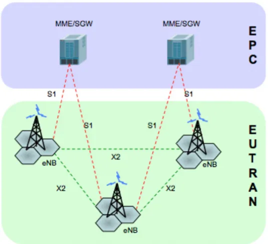
Figure 1.3 shows a simplified scheme of the LTE network architecture [8] , referred as Evolved Packet System (EPS).
Figure 2-3: LTE Evolved Packet System
The EPS is composed by two parts: access network and core network.
• The Evolved UMTS Terrestrial Radio Access Network (E-UTRAN) is the access network and it is composed by two different types of node:
o User Equipment, that is the devices used by mobile users for communication.
o Enhanced Node B (eNodeB), that is the cell base station, which is in control of all radio related functions in the fixed part of the system. • The Evolved Packet Core (EPC) is the core network and it is mainly composed
by two entities:
o Mobility Management Entity (MME), which takes care of the issues related to user identification, security and mobility management. o System Architecture Evolution Gateway (SAE-GW), which is the data
interface between the access network and external networks.
EPS nodes are connected among them through optical fiber links, in order to exchange both data and control information. The following interface are defined:
• S1 interface - between the eNodeBs and the EPC.
2.1.3 Protocols
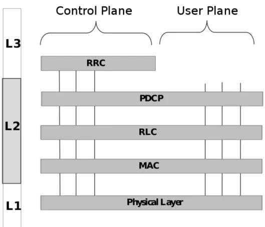
LTE is composed by several protocols, each performing specific functions. The LTE protocol stack [8] is shown in Figure 2-4.
Figure 2-4: LTE Protocol Stack
The stack distinctly manages information belonging to two different planes: the Control Plane and the User Plane. The Control Plane is composed by all control messages. The main control layer is RRC (Radio Resource Control), which manages the major part of control information exchanged between UE and eNodeB. The User Plane, instead, is composed by user data packets coming from and going to the IP network layer.
Data traffic is managed within the LTE stack by the layers listed below.
• Packet Data Convergence Protocol (PDCP) - This layer performs header compression/decompression on IP packets and ciphering/deciphering operations.
• Radio Link Control (RLC) - Depending on the RLC mode used1, this layer may perform error detection and correction with Automatic Repeat reQuest
(ARQ) procedures, concatenation and segmentation, in-sequence delivery and duplicate detection. It is also possible to have a timer-based mechanism to discard packets.
• Medium Access Control (MAC) - This layer performs multiplexing/demultiplexing of RLC Protocol Data Units (PDUs) in MAC PDUs and it is responsible for dynamic scheduling of users, both in downlink and in uplink. Within scheduling operations there is also the transport format selection, including transmission mode selection and link adaptation2. The interface between MAC and the physical layers is composed by Hybrid-ARQ (H-ARQ), which provides a mechanism for error correction by combining different retransmissions.
• Physical layer (PHY) - This layer provides the actual air interface to the radio channel. It is responsible for modulation and coding and performs antenna allocations according to the scheduling decisions. This layer encodes the data coming from higher layers into codewords for the transmission over the wireless channel. More details on the physical layer are given in 2.1.5.
A complete description of LTE protocols would require considerably more space and falls outside the scope of the present work. Further information about the LTE stack functionalities can be found in [8] or referring to the standard [83].
2.1.4 LTE Advanced
Release 10, called LTE Advanced, has been developed by 3GPP in order to fulfill the International Mobile Telecommunications Advanced (IMT-Advanced) requirements defined by ITU for 4G networks.
LTE Advanced is an evolution of Release 8 more than a new ver- sion3. It is backward compatible with the LTE technology and LTE Advanced networks are supposed to appear to legacy LTE terminals as standard LTE networks. The main differences between the two releases are summarized in Table 2-1.
LTE (Rel. 8) LTE Advanced (Rel. 10)
Peak Data Rate DL 300 Mbps 1 Gbps
Peak Data Rate UL 75 Mbps 500 Mbps
Maximum Bandwidth 20 MHz 100 MHz
DL MIMO Support up to 4 layers up to 8 layers Table 2-1: LTE versus LTE Advanced
In addition to the above differences, LTE Advanced introduces also the following features:
• The use of Relay nodes to extend cell coverage or use high MCSs also for border cell users. Relay nodes exchange information through the wireless channel with both the Donor eNodeB (DeNB) and UEs.
• The introduction of enhanced multi-antenna techniques, with Coordinated Multi-Point (CoMP) transmission and reception, and enhancements in Multi-User MIMO.
• The use of Distributed Antenna Systems (DAS), which form a network of spatially separated antenna nodes within the cell area, connected to the eNodeB by optical fiber links.
2.1.5 Physical Layer Details
To ease the comprehension of the work proposed in the following chapters, here we provide some details on LTE physical layer, mainly focusing our attention on the access schemes and the MIMO techniques used.
2.1.5.1 Access schemes
As we briefly noticed in 2.1.1, LTE uses OFDMA in downlink and SC-FDMA in uplink. Both access schemes can be viewed as multi-user versions of the Orthogonal Frequency Division Multiplexing (OFDM) digital modulation scheme. 3 Release 9 has some minor innovations with respect to the previous release. 4 Within this table, DL stands for downlink, while UL stands for uplink. By MIMO layer we mean a spatial channel In OFDM a large number of closely-spaced orthogonal subcarriers are used to carry data. Data are divided into several parallel streams sent over the various subcarriers and each subcarrier is modulated independently.
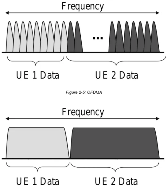
In OFDMA and SC-FDMA multiple access is achieved by assigning subsets of subcarriers to individual UEs. The distinguishing feature of SC-FDMA is that it leads to a single-carrier transmit signal, in contrast to OFDMA which is a multi-carrier transmission scheme (Figure 2-5 and Figure 2-6).
Thanks to the single-carrier structure, a prominent advantage of SC-FDMA over OFDMA is that its transmit signal has a lower Peak-to- Average Power Ratio (PAPR), thus leading to a lower power consumption: for this reason this access scheme has been adopted in uplink, where UE’s battery duration is crucial. On the other hand, OFDMA is used in the downlink direction to minimize receiver complexity and to enable frequency domain scheduling with flexibility in resource allocation. In fact the the multi-carrier nature of OFDMA allows the scheduler to allocate non contiguous frequency chunks to a given UE, while in SC-FDMA the allocation is continuous as only one symbol is transmitted at a time.
The modulation schemes available in LTE are QPSK (Quadrature Phase Shift Keying), 16QAM (Quadrature Amplitude Modulation) and 64QAM. For each scheme several coding rate are available.
Figure 2-5: OFDMA
Figure 2-6: SC-FDMA
Both in downlink and in uplink, frequency resources are logically divided in Resource Blocks (RBs), each consisting of 12 subcarriers. The RB is the minimum allocation unit in the frequency domain, while in the time domain allocation is done with the resolution of the 1 ms subframe, defined within a frame of 10 ms (Figure 2-7).
The 1 ms subframe is referred as Transmission Time Interval (TTI). Note that the Physical Resource Block (PRB) in the specifications refers to the 0.5 ms slot. However, being resources allocated using the TTI resolution, in the following we
will always use the expression “RB” to refer to an amount of resources corresponding to 180kHz in the frequency domain and 1 ms in the time domain. Each TTI the eNodeB scheduler allocates the RBs to the various UEs, selecting also the MIMO mode to use (see 2.1.5.2) and the MCS. For downlink, the MCS is chosen taking into account the Channel Quality Indicator (CQI) feedback specified by UEs. This CQI feedback can be either wideband or frequency selective. If wideband feedback is enabled, a single CQI value is specified by a UE for the whole system band. On the contrary, using frequency selective feedback a different CQI is specified for each sub-band, a sub-band being a group of contiguous RBs. Even if in the latter case the signaling overhead is bigger, selective feedback allows the scheduler to exploit multi-user diversity in the frequency domain, thus increasing system performance.
2.1.5.2 MIMO modes in LTE
LTE technology widely uses multi-antenna techniques in order to improve peak data rate, cell coverage and mean cell throughput. To achieve this various set of objectives, LTE adopts different MIMO technologies, including Spatial Multiplexing, Transmit Diversity and Multi-User MIMO [17].
The key idea of all MIMO techniques is to exploit also the spatial dimension of the wireless channel in order to get transmissions being either more efficient or more robust.
Figure 2-7: LTE frame structure 2.1.5.2.1 Spatial Multiplexing
Spatial Multiplexing allows the eNodeB to transmit independent data streams to a single UE on the same time-frequency resources exploiting different spatial channels, referred as layers. Using this technique the system bandwidth is virtually multiplied by a factor N, if N is the number of layers used.
There are two operation modes in Spatial Multiplexing: the closed- loop mode and the open-loop mode.
In the closed-loop mode, the eNodeB applies the spatial domain precoding on the transmitted signal taking into account the Precoding Matrix Indicator (PMI) reported by the UE, so that the transmitted signal matches with the spatial channel experienced by the UE. To support this mode in downlink, the UE needs to feedback the Rank Indicator (RI), the PMI and the CQI. The RI indicates the number of spatial layers that can be supported by the current channel experienced at the UE, while the CQI indicates the MCS the eNodeB should use to ensure that the block error probability will not exceed 10%.
Considering the case of M layers and N antennas, the precoding operation is defined by the relation
y = Wx
where x is the vector of M symbols in input to the precoder, W is the N × M precoding matrix and y is the vector of N symbols transmitted. The open-loop spatial multiplexing may be operated when reliable
PMI feedback is not available at the eNodeB (e.g. when the UE speed is not low enough or when the feedback overhead is too high). In this case, the feedback consists only of the RI and the CQI, and precoding operations are performed cyclically using a fixed set of precoding matrices.
Both in closed-loop and in open-loop Spatial Multiplexing, the maximum number of codewords a UE can receive is fixed to two, even if more spatial layers are available6. Therefore LTE defines the rules to map codewords to layers [5].
In LTE Release 8, Spatial Multiplexing is defined only for downlink and only for configurations with two or four transmit antennas. LTE Advanced extends the existing Spatial Multiplexing technologies, introducing the support for configurations with up to eight transmit antennas in downlink and up to four transmit antennas in uplink.
2.1.5.2.2 Transmit Diversity
Transmit Diversity is a MIMO transmission mode that exploits the spatial dimension of the wireless channel transmitting the same data stream over two or more different spatial layers, in order to increase the reliability of the transmission. The Transmit Diversity scheme is specified in LTE Release 8 for configurations with two or four transmit antennas in downlink and with two transmit antennas in uplink. Both in downlink and in uplink there is always a single codeword for each UE.
In LTE Release 8 downlink, the Space-Frequency Block Code (SFBC) is used if the eNodeB has two transmit antennas, while for eNodeBs having four transmit antennas a combination of the SFBC and the Frequency-Switched Transmit Diversity (FSTD) is used to provide robustness against the correlation between channels from different transmit antennas and for easier UE receiver implementation. In LTE Advanced downlink, Transmit Diversity is defined also for eight transmit antennas.
In uplink, the transmit antenna selection for UEs with two transmit antennas is specified. The antenna to be used for transmission can be selected either by the eNodeB (closed-loop transmit antenna selection) or autonomously by the UE itself (open-loop transmit antenna selection). In LTE Release 8, SFBC is not employed in uplink to avoid the additional cost required to implement two power amplifiers at the UE. LTE Advanced instead introduces the use of uplink Transmit Diversity with up to four transmit antennas.
2.1.5.2.3 Multi-User MIMO
Multi-User MIMO (MU-MIMO hereafter) is a generalized form of Spatial Multiplexing which allows the eNodeB to allocate multiple UEs in the same time-frequency resources, thus adding more flexibility to scheduling operations. MU-MIMO does not increase peak data rate, as Spatial Multiplexing does, but makes it possible to increase cell throughput even in presence of legacy UEs, having a
single receive antenna, or when channel conditions are not suitable for Spatial Multiplexing.
This transmission mode is supported both in uplink and in downlink by the LTE standard.
In uplink, the eNodeB can always schedule more than one UE to transmit in the same time-frequency resources, thus forming a MU- MIMO configuration known as Virtual MIMO (VMIMO). However, in order to be able to correctly differentiate and demodulate the signals transmitted by these UEs, the eNodeB needs to assign orthogonal reference signals to them.
In downlink, if a UE is configured to be in MU-MIMO, only rank-1 transmissions can be scheduled to that UE: that is a single codeword on a single layer is transmitted. The eNodeB can schedule multiple UEs in the same time-frequency resources using different rank-1 precoding matrices. The UE receives only the information about its own precoding matrix and decodes the signals received using the common reference signal together with the precoding information obtained from the control signaling.
For MU-MIMO transmission mode, the UE generates the PMI/CQI feedback without any knowledge about other simultaneously scheduled UEs. Hence, there could be a mismatch between the UE’s CQI report and the actual CQI experienced, due to the lack of knowledge of the interference caused by another UE scheduled simultaneously.
In LTE Advanced further enhancements have been proposed for MU-MIMO in order to improve system throughput beyond what is achieved in LTE. It is worth mentioning here the use of a maximum of four spatial layers, with up to two layers per UE, and the possibility to use an enhanced Channel State Information (CSI) feedback, using a two-matrix framework [6].
3 PROPOSED SCHEDULER
3.1 Introduction
In this chapter we investigate resource allocation in the downlink of a MIMO-capable LTE-A system at the MAC layer. The purpose is to provide a scheduling framework which accommodates different types of traffic, and exploits radio resources efficiently. We first show that computing the maximum throughput allocation in a MIMO-enabled LTE cell is practically unfeasible given the number of UEs involved and the scheduling timescale. Hence, we propose to separate the resource allocation problem into two sub-problems, namely transmission mode selection (TMS) and frequency-domain packet scheduling (FDPS). For the TMS problem, we propose a tunable polynomial-time algorithm. For the FPDS sub-problem, we propose a modular framework that allows different types of services to be accommodated on demand. The basic block is an opportunistic allocation, which maximizes the throughput. Other blocks can be added if traffics with fairness (i.e., minimum throughput) or QoS (i.e., deadline) constraints are to be considered. We show via simulation that the opportunistic version of the FPDS achieves near-optimal cell throughput, and that adding QoS and fairness only entails a modest throughput loss.
To the best of our knowledge, no previous work covers multi-service scheduling under MIMO constraints. Those which consider single aspects (e.g., only throughput maximization, or fairness, under MU-MIMO) often rely on simplifications and idealizations that make them unsuitable for the LTE-A environment. Some either ignore MU-MIMO (e.g. 16), or assume arbitrary, out-of-standard MU-MIMO UE pairings in the same TTI (e.g. 17-18), others neglect the TMS problem (which greatly influences the cell throughput) by forcing a priori a single transmission mode (e.g. 19-20).
3.2 LTE-A Resource allocation and
constraints
Hereafter we describe the LTE-A system, focusing on those features which are more relevant to the resource allocation problem in the downlink direction at the MAC layer.
In LTE, transmissions are arranged in time slots called Transmission Time Intervals, (TTIs), whose duration is 1ms. At the logical (MAC) level, the eNodeB allocates a vector of (Virtual) Resource Blocks (RBs) to its associated UEs on each TTI. Each RB carries a fixed number of symbols, which translate to different amounts of bits depending on the modulation and coding scheme (MCS) used by the eNodeB on that RB. In general, more information-dense modulations (e.g., up to 64QAM, which yields 6 bits per symbol) are favored when a better channel to the UE is perceived. The quality of the wireless channel, in fact, varies over both time and frequency. For this reason, UEs report their perceived downlink channel state to the eNodeB as a Channel Quality Indicator (CQI). The CQI is an index in a standard table, computed by the UE according to the measured Signal to Noise Ratio (SNR), and determines the MCS that the eNodeB should use and the number of bits per RB, called Transport Block Size, TBS. Accordingly, we will
sometimes use the word CQI to refer either of the latter two, trading a little description accuracy for conciseness and ease of reading.
Depending on the settings, either one wideband CQI or several per logical sub-band x CQIs can be reported. In the first case, the CQI is an average measure of the channel quality over the whole OFDMA frequency spectrum. In the latter case, the OFDMA spectrum is partitioned in logical sub-bands (LSBs), and UEs report the average channel status on each of these. In the latter case, an increased reporting overhead is the price to be paid to enable the eNodeB to exploit frequency selectivity, i.e. to schedule UEs on those RBs where a higher-order MCS can be exploited. While the eNodeB is free to use whichever MCS it sees fit (regardless of the reported CQI) to address a UE, exceeding the reported CQI increases the likelihood of decoding errors at the UE. Retransmissions are handled by the hybrid-ARQ (H-ARQ) processes, which eat out some RBs from subsequent TTI frames. While a certain amount of retransmissions is unavoidable in a wireless environment, it is obvious that a well-designed scheduler should not waste resources by pushing UE receivers beyond their limits.
In order to build a frame in a TTI, the eNodeB scheduler selects which UEs are going to be targeted, using which transmission mode (e.g., S-MUX, TD, MU-MIMO), in which LSBs (in case of frequency-selective CQIs) using which MCS to guarantee reliable transmission. These decisions are made, either sequentially or jointly, based on the reported CQIs, the backlog and type of traffic of each UE, the QoS requirements, etc. A scheduler might aim to maximize the cell throughput, to ensure fairness among UEs (i.e., to guarantee that UEs reporting low CQIs for many TTIs do not starve), or to meet deadline guarantees with real-time traffic such as VoIP, or to combine any of the above features.
The key idea of all MIMO techniques is to exploit the spatial dimension of the wireless channel in order to achieve more efficient or robust transmissions. At the MAC layer, MIMO transmission implies sending twice the usual amount of information on one RB, as if space were a third dimension. MIMO modes differ as for i) whether one or two different codewords are transmitted, and ii) whether one or two UEs are targeted simultaneously. This yields a total of three combinations: one codeword to one UE, however replicated to increase likelihood of reception (Transmission Diversity), two codewords to the same UE (Spatial Multiplexing), two codewords to two UEs (Multi-User MIMO).
The practicability of each transmission mode for a given UE depends on information fed back by the UEs, such as the Precoding Matrix Indicator and Rank Indicator. Depending on the latter two, in fact, a UE may or may not support more demanding modes, such as S-MUX. Furthermore two UEs may or may not be paired MU-MIMO depending on these. While these aspects are indeed crucial to the LTE system, our scheduling framework is largely independent of physical details. For this reason, we refer the interested reader to the standards [2] or to the abundant literature on the subject (e.g., [8]).
A UE reports one CQI per codeword, i.e. one per MU-MIMO and TD, and two for S-MUX. The CQI is related to the MIMO mode the UE is addressed with. This means that the CQI of a UE served in TD may not describe the channel quality related to a hypothetical service in S-MUX or MU-MIMO in the same TTI. This makes the TMS problem all but a wild guess, unless correlation between the channel reports of the various MIMO modes is assumed. Such correlation has been analyzed in [25], where authors – using detailed link-level simulations – show that the CQI for one
MIMO mode can be translated to that of another one by applying a suitable offset. For instance, if a UE reports a CQI equal to c for both codewords in S-MUX, it is likely that it can be served with a higher CQI if paired in MU-MIMO with another UEs (under the physical conditions that allow so), as the channels to two different UEs would be more spatially separated than those to the same UE.
There are some constraints that are inherent to resource allocation in LTE-A. Although they do complicate the problem, neglecting them leads to unfeasible allocations. The first constraint will be called one-MIMO-mode: a UE can only use one of the above MIMO modes in a TTI. For instance, it cannot receive data using TD on one RB and S-MUX on another RB. The second constraint further specifies the first one for MU-MIMO allocations, and will be called MU-MIMO-pairing constraint: UE must be paired with only one UE in MU-MIMO in a TTI, and both UEs have to be allocated on exactly the same RBs. The above constraints are related to the TMS decision. The third one is instead related to the MCS selection, and will be called one-MCS constraint: a codeword must be transmitted to a UE using the same MCS on all the RBs it occupies, despite the fact that the UE may report different CQIs on these RBs (e.g., when these belong to different LSBs). In order not to increase the error rate, the minimum CQI should be adhered to for all the RBs in a codeword. Hence, the amount of data that an UE can reliably receive is, in general, less than the sum of the TBS corresponding to the CQIs reported for each RB.
3.3 System Model and Throughput-Optimal
Scheduling Problem
We focus on the downlink of an LTE-A cell, which is managed by a the eNodeB downlink MAC scheduler. The scheduler serves UEs. A UE may have one or more streams of traffic queued at the eNodeB. We denote with the overall backlog of UE , which we assume to be arbitrary divisible. During each TTI, the scheduler allocates a frame of RB to the UEs. We assume that the RB are grouped into logical sub-bands (LSB), and is the number of RBs on LSB , . We assume that UEs can use TD, S-MUX and MU-MIMO, and that the scheduler can alternate among the three modes on a per-TTI basis. Furthermore, we assume that the eNodeB can multiplex at most two codewords on the same RB, i.e. up to two streams can be sent, whether to the same UE (S-MUX) or to a pair (MU-MIMO).
We assume that full feedback is available at the eNodeB, meaning that the latter is aware of the rate that it may use on every LSB to address a UE (or pair thereof) for each MIMO mode. The means through which such information are made available at the scheduler concern the physical layer, and are thus outside the scope of this paper. To remark the viability of this hypothesis, however, we recall that it is customary to compute estimates of the rates in the various MIMO modes by offsetting standard UE reporting 25.
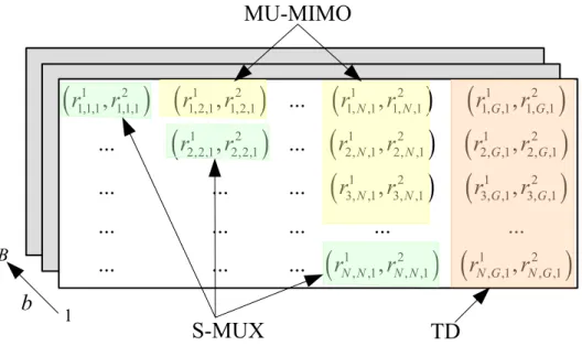
The above information is summarized at the eNodeB in a three-dimensional rate matrix (RM), shown in Figure 3-1. The latter has rows, columns, and layers in the third dimension. Each element of the matrix is a couple .
i j N Ti i M B Mb b 1≤ b ≤ B N N+1 B ri, j,b 1 ,ri, j,b 2
(
)
Value (resp. ), with , represents the rate (i.e. the number of bits) that can be achieved by UE i (resp. UE j) when UEs are scheduled together in MU-MIMO on a RB of LSB . When , the same information represents the S-MUX rate for either stream of UE i. Finally, when , we assume that is the rate for UE i served in TD, and we assume that
. We will sometimes use the sum as the sum rate of the matrix element. Since, under MU-MIMO (i.e. when ), it is , we can limit ourselves to considering only the matrix elements with . For ease of exposition, we will sometimes refer to “pairs of UEs” served on an RB, overlooking the fact that a single UE is targeted in S-MUX (in which case it is “paired with itself”) and in TD (in which case it is paired with the ghost UE
). If needed, the present model allows for a single, wideband CQI (in which case ). We leave it to the interested reader to simplify the algorithms presented in the following under that condition. We also observe that the interference from neighboring eNodeBs can be incorporated in this model, just by reducing the UE’s rates on certain LSBs.
Figure 3-1: the Rate Matrix
ri, j,b 1 ri, j,b 2 i≠ j, j ≠ n +1 i, j b i= j j= N +1 ri,N1 +1,b ri,N2 +1,b= 0 ∀i,b mi, j,b= ri, j,b 1 + r i, j,b 2 i≠ j, j ≠ n +1 ri, j,b 1 = r j,i,b 2 j≥ i G= N +1 B= 1
(
) (
)
(
) (
)
(
)
(
) (
)
(
) (
)
(
)
1 2 1 2 1 2 1 2 1,1,1 1,1,1 1,2,1 1,2,1 1, ,1 1, ,1 1, ,1 1, ,1 1 2 1 2 1 2 2,2,1 2,2,1 2, ,1 2, ,1 2, ,1 2, ,1 1 2 1 2 3, ,1 3, ,1 3, ,1 3, ,1 1 2 1 , ,1 , ,1 , ,1,
,
...
,
,
...
,
...
,
,
...
...
...
,
,
...
...
...
...
...
...
...
...
,
,
N N G G N N G G N N G G N N N N N Gr
r
r
r
r
r
r
r
r
r
r
r
r
r
r
r
r
r
r
r
(
r
2)
, ,1 N Gr
b
1
B
TD
S-MUX
MU-MIMO
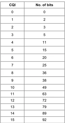
CQI No. of bits 0 0 1 2 2 3 3 5 4 11 5 15 6 20 7 25 8 36 9 38 10 49 11 63 12 72 13 79 14 89 15 92
Table 3-1: Number of bits per CQI
We assume for simplicity that the number of bits that can be transmitted to the UE is linearly increasing with the number of RBs allocated to it. That number is determined by the CQI reported in Table 3-1, which is obtained by averaging the values reported in [5].
Our goal is to devise a resource allocation algorithm that i) accommodates different types of traffic simultaneously; and ii) exploits frequency diversity among the LSBs, thus utilizing the radio resources effectively.
Before explaining our solution (which is the subject of the next section), we show that maximizing resource effectiveness, i.e., objective iii) alone, under the LTE constraints (i.e., one-MIMO-mode, MU-MIMO-pairing, one-MCS) is beyond achievable in practical scenarios. We formulate the maximum-throughput allocation problem (MTAP) as an optimization problem, and show that solving it optimally takes an unfeasible time.
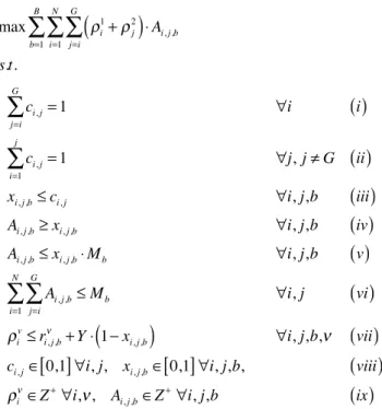
The MTAP is reported in Figure 3-2, under a full buffer approximation1 (i.e., ). Binary variables state whether are paired or not, while state whether will be allocated RBs in LSB , the number of those RBs being represented by . Each UE i has two rate variables , representing the UE’s rate on the two streams it may receive. The objective is to maximize the overall rate on all the LSBs. Constraint (i-ii) model the one-MIMO-mode and MU-MIMO-pairing constraints. Constraints (iii) states that a pair can only be allocated RBs out of a given LSB if they are paired at all. Constraints (iv-v) ensure that no more than RBs are allocated on each LSB, and that if . Constraint (vii) implements the one-MCS constraint. Let be a very large positive constant: for each LSBs where actually have RBs allocated (i.e., those with , otherwise the constraints are obviously verified), the rate of the codewords cannot exceed the achievable rates. Note that, since appear only in those constraints, as well as in the objective function with a positive sign, some constraints of this block will be active at the optimum, i.e. equality will hold in some of (vii), which implies that the rate used on each codeword will actually be one of those reported in the RM. Constraint (viii-ix) express that , are binary, and that , are integer.
1 Taking into account finite buffers in the MTAP is not conceptually difficult, but requires one to model padding, i.e. the number of bits that do not contain useful information in a RB. This makes the model more cumbersome than it already is.
∀i, Ti= ∞ ci, j i, j xi, j,b i, j b Ai, j,b ρi 1,ρ i 2 Mb Ai, j,b> 0 xi, j,b= 1 Y i, j
( )
xi, j,b= 1 ρi 1,ρ i 2 ci, j xi, j,b ρi 1,ρ i 2 A i, j,bFigure 3-2: Mathematical model for the MTAP
The MTAP has variables, a quadratic objective function and
linear constraints. This makes it an integer quadratic optimization problem. Unfortunately, the objective function is non-convex, which makes the problem particularly hard to solve even at small scales (non-convex problems are NP-hard in general). The non-convexity follows from the one-MCS constraint: without the latter, variables could be replaced by constants , which would make the objective function linear. Broadly speaking, selecting both an arbitrary number of LSBs and a single transmission rate as a function of per-LSB reports inevitably leads to a quadratic (hence non-convex) objective function. For instance, using the average CQI (instead of the minimum) would not make a difference.
One might wonder whether computing a resource allocation neglecting the one-MCS constraint, and then superimposing it in order to make the allocation feasible, could be a viable option. On one hand, this would still involve solving an integer-linear problem (which is probably too hard to be solved in a millisecond). On the other hand, it may lead to largely suboptimal throughputs, as shown in the following example.
Example:
Consider a system with 2 UEs and 2 LSB, each one with only one RB. Assume the following RM: max ρi1+ρ j 2
(
)
⋅ Ai, j,b j=i G∑
i=1 N∑
b=1 B∑
s.t. ci, j j=i G∑
= 1 ∀i( )
i ci, j i=1 j∑
= 1 ∀j, j ≠ G( )
ii xi, j,b≤ ci, j ∀i, j,b( )
iii Ai, j,b≥ xi, j,b ∀i, j,b( )
iv Ai, j,b≤ xi, j,b⋅ Mb ∀i, j,b( )
v Ai, j,b j=i G∑
i=1 N∑
≤ Mb ∀i, j( )
vi ρi v≤ r i, j,b ν +Y ⋅ 1− x i, j,b(
)
∀i, j,b,ν( )
viici, j∈ 0,1
[ ]
∀i, j, xi, j,b∈ 0,1[ ]
∀i, j,b,( )
viiiρi ν∈Z+∀i,ν, A i, j,b∈Z +∀i, j,b ix
( )
O N2 B( )
O N2 B( )
ρi 1,ρ i 2 r i, j,b 1 ,ri, j,b 2 RM1= 10,10(
)
( )
9,9(
11,0)
−( )
2,2( )
3,0 ⎡ ⎣ ⎢ ⎢ ⎤ ⎦ ⎥ ⎥RM2= 5,5( )
( )
9,9( )
6,0 −( )
3, 3( )
4,0 ⎡ ⎣ ⎢ ⎢ ⎤ ⎦ ⎥ ⎥The maximum throughput is achieved with both UEs in MU-MIMO, and it is equal to . Without the one-MCS constraint, instead, the throughput-optimal allocation is achieved with both UEs in S-MUX, and its throughput is:
However, if the one-MCS constraint is enforced to make the latter allocation feasible, the overall throughput is reduced to:
, i.e. considerably less than the optimum.
3.4 Polynomial-time Opportunistic
Scheduling
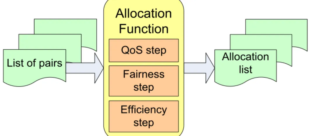
In order to make the problem tractable, we split it in two: first we solve the TMS problem, and then we solve the allocation problem given a TMS, as in Figure 3-3. The TMS algorithm takes the RM as an input, and produces a pair list L as an output. The allocation function takes the pair list as an input, and actually allocates the RBs to the UE pairs, i.e., outputs an allocation list of up to tuples
, which actually populate the frame for the TTI.
Such partition comes with a twofold advantage. First of all, it allows us to partition the LTE constraints as well, thus greatly simplifying the problem: the one-MIMO-mode and MU-MIMO-pairing constraints are taken care of in the TMS algorithm, and the one-MCS constraint is instead considered in the allocation function. Second, it allows different algorithms to be plugged in each block, e.g. to achieve different trade-offs between complexity and effectiveness. For instance, different allocation functions can be envisaged to account for fairness, QoS, throughput effectiveness, and so on, without modifying the TMS algorithms. We will actually exploit this concept in section 3.5.
Figure 3-3: The resource allocation framework 9+ 9
(
)
⋅2 = 3610+10
(
)
+ 5 + 5(
)
+ 2 + 2(
)
+ 3+ 3(
)
= 402⋅ min 10,5
(
{
}
+ min 10,5{
}
)
+ 2 ⋅ min 2,3(
{ }
+ min 2,3{ }
)
= 28M i, j,b
{
}
1,1,1 1,2,1 1, ,1 1, ,1 2,2,1 2, ,1 2, ,1 3, ,1 3, ,1 , ,1 , ,1 ... 0 ... 0 0 ... ... ... ... ... ... 0 0 ... N G N G N G N N N G m m m m m m m m m m mList of pairs Allocation list
TMS algorithm
Allocation function
3.4.1 TMS algorithms
The objective of a TMS algorithm is to favor, for each UE, the transmission modes that might lead to a higher throughput. “Might”, since the throughput will depend on which LSBs are allocated to which UE pair, a decision which is made by the allocation function only later. One should decide, at this stage, whether it is preferable to select a transmission mode that exhibits a high rate peak on possibly a single LSB and a poor rate everywhere else, or one whose peak is less pronounced, but consistent on more than one LSB. We propose an algorithm called K-max, which can be tuned to trade off between frequency selectivity and average throughput, thus allowing either of the extreme behaviors in the above example.
K-max computes a bi-dimensional score matrix (SM), whose elements are the sum of the K largest sum rates over the third (b) dimension in the RM. K is a tunable parameter. When , the algorithm selects , i.e. the largest sum rate achieved by pair on the whole frame. For , it selects , i.e. the sum of the sum rates on all the LSBs. Practically speaking, the value of determines the number of LSBs deemed meaningful to contribute to rate peaks.
The K-max explores the SM cyclically as follows:
• select from the SM
• add to the pair list L;
• purge the SM for the next iteration: zero the row and column and, if (i.e., MU-MIMO is being considered), zero the row and column as well (consistent with the one-MIMO-mode and the MU-MIMO-pairing constraints).
The cycle terminates when all UE pairs have been assigned a transmission mode. The pseudo-code of K-max is shown in Figure 3-4.
N× G si, j mi, j,b K= 1 si, j= max 1≤b≤B