ALMA MATER STUDIORUM - UNIVERSITÀ DI BOLOGNA
SCUOLA DI INGEGNERIA E ARCHITETTURA
DISI
INGEGNERIA INFORMATICA
TESI DI LAUREA
in
Intelligenza Artificiale
Virtual Sensing Technology applied to a swarm of autonomous
robots
Tesi di Laurea di:
Relatrice:
MATTIA SALVARO
Chiar.ma Prof.ssa MICHELA MILANO
Correlatore:
Prof. MAURO BIRATTARI
Anno Accademico 2013/14
Sessione III
Acknowledgements
I would like to express my gratitude to my supervisors Andreagiovanni Reina and Gianpiero Francesca, for their patient and essential guidance throughout my internship at the IRIDIA lab, and afterwards during the writing of this the-sis. Thanks to Dr. Carlo Pinciroli for his important contribution in some key passages of my project. Thanks to Professor Mauro Birattari for wisely coordi-nating my project activities and granting me access to the resources I needed. Thanks to Professor Michela Milano for introducing me such an interesting dis-cipline and such an advanced laboratory like the IRIDIA lab. Thanks to all the people at the IRIDIA lab for such an intense scientific experience.
I would like to thank also my family: my parents and grandparents that never stop supporting me, morally and economically, during this long and sometimes difficult University period. Thanks to all the old friends and new friends that made this long period so fun, and thanks to the long list of flatmates that made cohabitation a wonderful experience. Finally, a special thanks to the patient person that supported me during my months abroad and took care of me in the writing phase, Manuela Dibenedetto. I would like to share the joy of this achievement with you all.
Thank you, Mattia.
Abstract
This thesis proposes a novel technology in the field of swarm robotics that allows a swarm of robots to sense a virtual environment through virtual sensors. Virtual sensing is a desirable and helpful technology in swarm robotics research activity, because it allows the researchers to ef-ficiently and quickly perform experiments otherwise more expensive and time consuming, or even impossible. In particular, we envision two useful applications for virtual sensing technology. On the one hand, it is possible to prototype and foresee the effects of a new sensor on a robot swarm, before producing it. On the other hand, thanks to this technology it is possible to study the behaviour of robots operating in environments that are not easily reproducible inside a lab for safety reasons or just because physically infeasible.
The use of virtual sensing technology for sensor prototyping aims to foresee the behaviour of the swarm enhanced with new or more powerful sensors, without producing the hardware. Sensor prototyping can be used to tune a new sensor or perform performance comparison tests between alternative types of sensors. This kind of prototyping experiments can be performed through the presented tool, that allows to rapidly develop and test software virtual sensors of different typologies and quality, emulat-ing the behaviour of several hardware real sensors. By investigatemulat-ing on which sensors is better to invest, a researcher can minimize the sensors’ production cost while achieving a given swarm performance.
Through augmented reality, it is possible to test the performance of the swarm in a desired virtual environment that cannot be set into the lab for physical, logistic or economical reasons. The virtual environment is sensed by the robots through properly designed virtual sensors. Virtual sensing technology allows a researcher to quickly carry out real robots experiment in challenging scenarios without all the required hardware and environment.
Virtual sensor experiments are hybrid experiments between purely simulated and purely real experiments. Indeed, virtual sensors experi-ments join the real world dynamics of the real robots to the simulated dy-namics of the virtual sensors. The benefits of virtual sensing experiments compared to purely real experiments are presented above. The benefit of virtual sensor experiments compared to purely simulated experiment consists in the fact that the former are one step closer to reality than the latter. Hence, hybrid experiments are closer to reality than purely simulated ones.
The proposed system is composed of a tracking system, a simulator and a swarm of robots. The multi-camera tracking system acquires the position of the robots in the arena. This information is then processed inside a simulator, and the output is delivered to the real robots as virtual sensor values. In Chapter 2, I describe the functioning of the tracking system. In Chapter 3, I present the components of the simulator that realize the virtual sensing environment. In Chapter 4, I illustrate the implementation of three virtual sensors. In Chapter 5, I illustrate the effectiveness of the proposed technology by presenting a simple experiment involving a swarm of 15 robots.
This work led to the writing of an international conference article that has been lately submitted [18]. Moreover, working on the presented tech-nology, I had the chance to collaborate to a set of scientific experiments that resulted in an international conference paper [6] and an international journal article currently under review [5]. Furthermore, I contributed to
the implementation and setup of the tracking system and co-authored the relative technical report which documents its functioning [22].
Sommario
Questo lavoro presenta un’innovativa tecnologia nel campo della robot-ica degli sciami, o swarm robotics. Il sistema progettato permette ad uno sciame di robot di percepire un ambiente di realt`a simulata grazie a dei sensori virtuali. La tecnologia dei sensori virtuali offre un’opportunit`a allettante nell’attivit`a di ricerca in swarm robotics, perch´e permette ai ricercatori di effettuare in modo veloce ed efficiente esperimenti che altri-menti sarebbero pi`u costosi in termini di tempo e denaro, o addirittura irrealizzabili. Questa tecnologia si dimostra utile in particolare per due applicazioni: da un lato rende possibile prototipare e prevedere gli effetti che avrebbe sul comportamento dello sciame l’aggiunta di un nuovo sen-sore prima di produrlo; dall’altro permette di studiare il comportamento dello sciame in ambienti che non siano facilmente riproducibili all’interno di un laboratorio, per motivi di sicurezza o anche solo perch´e fisicamente impossibili.
L’uso dei sensori virtuali per la prototipazione mira a simulare il com-portamento dello sciame migliorato con l’aggiunta di sensori nuovi o pi`u af-fidabili, prima ancora di produrne l’hardware. Prototipare un sensore per-mette di per-mettere a punto un nuovo sensore o di confrontare le prestazioni di tipi di sensori alternativi. Questo tipo di studi possono essere condotti con lo strumento presentato in questo lavoro, che permette di sviluppare via software e testare rapidamente sensori virtuali di diverse tipologie e liv-elli di qualit`a, simulando il comportamento di sensori reali di varia natura. In alternativa, lo strumento pu`o essere utilizzato per indagare su quale o quali sensori reali sia meglio investire in modo tale da ottenere un dato livello di prestazione dello sciame, minimizzando il costo di produzione.
Con il sistema di realt`a aumentata, `e possibile testare le prestazioni di uno sciame che opera in un ambiente che non pu`o essere ricostruito in un laboratorio per motivi di natura fisica, logistica o economica. L’ambiante virtuale `e percepito dai robot reali attraverso sensori virtuali progettati ad-hoc. Questa tecnologia pu`o essere sfruttata per effettuare velocemente esperimenti con robot reali in scenari innovativi, senza dover predisporre l’ambiente n´e avere l’hardware necessario a bordo dei robot.
Gli esperimenti con i sensori virtuali caratterizzano un ibrido tra gli esperimenti puramente simulati e quelli puramente reali. Infatti, gli esper-imenti con sensori virtuali uniscono le dinamiche reali dei robot a quelle simulate dei sensori virtuali. I benefici degli esperimenti ibridi rispetto a quelli puramente reali sono stati descritti sopra. Il vantaggio degli esperi-menti ibridi rispetto a quelli puramente simulati invece consiste nel fatto che i primi sono si avvicinano di pi`u alla realt`a rispetto agli ultimi. Di conseguenza anche i loro risultati saranno pi`u congruenti a quelli reali.
Il sistema progettato `e composto da un sistema di tracking, un simula-tore ed uno sciame di robot. Il sistema di tracking multi camera acquisisce la posizione dei robot nell’arena, ed invia i dati ad un simulatore che li processa. L’output che ne risulta sono i valori dei sensori virtuali, che vengono inviati ai robot reali attraverso una rete Wi-Fi. Nel Capitolo 2 descrivo il funzionamento del sistema di tracking, nel Capitolo 3 presento le componenti del simulatore che realizzano l’ambiente per i sensori vir-tuali, nel Capitolo 4 mostro l’implementazione di tre sensori virvir-tuali, nel Capitolo 5 illustro l’efficacia della tecnologia proposta con un semplice esperimento con 15 robot reali.
Questo lavoro ha portato alla stesura di un articolo per una conferenza internazionale che `e stato presentato di recente. Lavorando su questo pro-getto, ho anche avuto la possibilit`a di collaborare ad una serie di
esperi-menti scientifici che sono risultati in un articolo per una conferenza inter-nazionale [6] e un articolo per una rivista scientifica interinter-nazionale, al mo-mento in fase di revisione [5]. Inoltre, ho contribuito all’implementazione e messa a punto del sistema di tracking e sono coautore della relativa relazione tecnica che ne documenta il funzionamento [22].
Contents
1 Introduction 3
1.1 Swarm robotics . . . 3
1.2 Motivations . . . 5
1.3 Overview . . . 6
1.4 Virtual Sensing: state of the art . . . 8
1.5 Original contribution . . . 9
1.6 Thesis structure . . . 10
2 Arena Tracking System 11 2.1 Halcon API Layer . . . 13
2.2 Arena Tracking System API Layer . . . 18
2.2.1 Detection and optimisation . . . 19
2.2.2 Configuration . . . 22
2.3 Arena Tracking System Application Layer . . . 27
2.3.1 Arena Tracking System Viewer . . . 27
2.3.2 Arena Tracking System Server . . . 28
3 Arena Tracking System Virtual Sensing Plugin 30 3.1 ARGoS overview . . . 30
3.2 Virtual sensing with ARGoS . . . 37
3.3 Arena Tracking System Virtual Sensing Plugin Simulator Module 40 3.3.1 Arena Tracking System Client . . . 41
3.3.2 Arena Tracking System Physics Engine . . . 45
3.3.3 ARGoS Virtual Sensor Server . . . 47
3.3.4 Virtual Sensors Simulator Module . . . 49
3.4 Arena Tracking System Virtual Sensing Plugin E-Puck Module . 51 3.4.1 Virtual Sensor Client . . . 52
3.4.2 Arena Tracking System Real E-Puck . . . 54
3.4.3 Virtual Sensors Real Robot Module . . . 56
4 Virtual Sensors implementation 59 4.1 Control Interface . . . 59
4.2 Simulator . . . 61
4.2.1 Ground Virtual Sensor Simulator Module . . . 61
4.2.2 Light Virtual Sensor Simulator Module . . . 64
4.2.3 Pollutant Virtual Sensor Simulator Module . . . 67
4.3 Real Robot . . . 71
5 Validation through real robots experiment 74
6 Conclusions and future work 77
Chapter 1
Introduction
In this thesis, I present a tool to help researchers conducting experiments in the field of swarm robotics. The tool enhances the experimental experience enabling two useful functions: augmented reality for the robots, and robots’ sensor prototyping. The project had been entirely developed at the IRIDIA [8] lab, Universit´e Libre de Bruxelles, Belgium, under the supervision of profes-sor Mauro Birattari and Ph.D students Andreagiovanni Reina and Gianpiero Francesca. To better understand the field in which my work settles and its possible applications, I first introduce swarm robotics. Then, I will explain the motivations and goal of the work, followed by an overview of the entire system. Then I summarise the state of the art relevant to the object of my study, that is virtual sensing technology for swarm robotics. At the end of the chapter I illustrate what is my original contribution to this work, and finally I explain how the thesis is structured.
1.1
Swarm robotics
Swarm robotics [4] is a branch of Artificial Intelligence that focuses on the design of self organised groups of autonomous robots that cooperate to achieve a common goal. Swarm robotics assumes absence of any form of centralised control or communication infrastructure. Cooperation and coordination are obtained exclusively through numerous local interactions among the robots. The task of the robot swarm designer is to create individual robot behaviours that allow the swarm to satisfy the global requirements, while exploiting only local interactions among the robots. Robots local interactions can be between robots, or between robots and the environment.
According to the definitions above, the advantageous characteristics of swarm robotics are: fault tolerance, scalability and flexibility. Fault tolerance results from the decentralised behaviour and the high redundancy of the swarm. The failure of one or more single units should not affect the collective behaviour if there is no centralised control, no predefined roles inside the swarm and a sufficient degree of redundancy. Scalability is obtained thanks to local interac-tions. Global performance is proportional to the number of robots cooperating in the swarm, and no reprogramming of the robots is needed after the swarm size is changed. Flexibility is accomplished by the distributed and self
organ-ised essence of the swarm, that allows the swarm to cope with time-variant environment for instance through dynamic task allocation among the robots.
The potential applications envisioned for swarm robotics are numerous and diverse. In fact, swarm robotics is well suited for tackling tasks such as search and rescue, demining, construction in hostile environment like space or under-water, post-disaster recover. Search and rescue and demining are dangerous tasks for human beings. Employing a fault tolerant swarm of robots for this task is desirable to avoid human losses, because robots losses are tolerated by the system. Thanks to scalability the task execution time can be accelerated by pouring more robots in the swarm. Besides being human threatening, hos-tile environments usually lacks of any kind of communication infrastructure. Swarm robotics perfectly fits this lack of global communication, because the swarm robotic system relies only on local communication for coordination and cooperation between robots. These low requirements make swarm robotics a viable solution for space or underwater construction. Another human hostile kind of environment is a post-disaster environment: earthquakes, floods, nu-clear power plant accidents, wars. Swarm robotics can be employed for sites re-covering in these kinds of situations. Assuming for instance a post-earthquake scenario. The tasks to be performed for earthquake recovery are numerous: search and rescue, demolition of unstable buildings, securing of damaged build-ings, pipelines, electrics and hydro systems. Thanks to its flexibility, the swarm is able to allocate the tasks to the robots dynamically, adapting the number of robots assigned to one task to the needs of the time variant environment.
According to Brambilla et al. [3], a swarm robotics system can be modelled both at microscopic and macroscopic level. Microscopic models consider the single robots individually, analysing the unit interactions with each other or with the environment. Different levels of abstraction make the model more or less realistic but also more or less complex for design purposes. Macroscopic models take into account the whole swarm as a unique entity. Such models provide a high level perspective of the system and allow a designer to focus on the properties that the swarm requires to achieve.
In reality, requirements are expressed at swarm level, while design must be actualised at microscopic level. Today, a general engineering methodology for swarm robotics design is still missing, and control software for swarm robotic systems is produced in two ways: manual and automatic. In manual design, the gap between the two levels is filled by the individual ability and expe-rience of the designer, making of swarm design a kind of art rather than a strict discipline. The designer follows a trial and error approach, developing the single robot behaviour, testing and improving it until the desired collective behaviour is obtained. The most used software architecture is the probabilistic finite state machine, but another common approach is based on virtual physics, where robots and environment interact through virtual forces. While proba-bilistic finite state machine is more suited for tasks like aggregation [20], chain formation [15] or task allocation [11, 10], virtual physics is a better approach for spatial organising tasks, for example pattern formation [21] and collective motion [19].
The main automatic design method is called evolutionary robotics [24]. With this technique, single robots are controlled by a neural network whose param-eters are obtained through artificial evolution. The main drawback of the au-tomatic design method, is that defining an effective setting is usually a difficult
problem. A novel approach to automatic design, called AutoMoDE, has been proposed lately by Francesca et al. [5].
In the next section I will list the open issues in swarm robotics and the motivations that sustain my work
1.2
Motivations
The application areas mentioned above are only potential. In fact, the complex-ity of the swarm design and the envisioned applications themselves, prevented swarm robotics to take off in the real world. At date, swarm robotics research is still confined inside research laboratories. Researchers make extensive use of simulation tools to test and evaluate their algorithms, because real robot experiments, even in a highly controlled environment, are still quite an issue. Compared to simulation, real robots experiments are very expensive in terms of time and work, though often necessary. Validation of the control software through real robot experiments is demanded by a typical incongruity between simulated and real robot experiments results. Simulators are unable to model all the aspects of reality, and depending on the level of abstraction, reality is more or less simplified. This simplification, or abstraction of reality, leads to a mismatch between reality and simulation, called reality gap. The presence of the reality gap makes real robots validation necessary in most of the cases, how-ever the execution of real robots experiments is not so trivial and slows down the whole control software production process.
Given the current conditions in swarm robotics research, my work aims to help researchers carrying out their experimental indoor activity and to ease the usage of real robots thanks to an augmented reality environment. I implemented a system that enables virtual sensing on a swarm of robots. Such a system affects the experimental experience in two ways. First, the architecture provides an augmented reality system to allow the creation of a hybrid environment where real robots can sense the simulated environment by means of virtual sensors. Second, the system can be used as a tool to prototype sensors that are currently unavailable on board the robots.
The researcher can exploit augmented reality to create an environment that is not physically replicable inside labs. The inability to replicate the environ-ment can be due to safety reasons, for example dangerous radiations or spreading wildfire, or for practical and economical reasons. For example, the researcher can insert in the environment any source of wave radiation, including light, and implement the corresponding virtual sensor on the robots. As an example, I con-sider the experiment exposed in [7], where infrared transmitters define different areas in which the space is divided. Let’s assume that the robots are equipped with infrared receivers, but the transmitters are not immediately available or must be bought. Virtualising the transmitters and implementing the infrared virtual sensor for the robots allow the researcher to start the experiments right away. Considering the same experiment, the wall of the maze in which the robots operate can be virtualised as well. Walls, objects and obstacles virtual-isation gives the researcher high flexibility and simplifies in terms of time and material the set up of the experimental environment.
The system can also be seen under another point of view. In a situation in which the researcher has the chance to upgrade the robots with new pieces of
hardware, virtual sensors can help in prototyping the real sensors before their production. Virtual sensing technology can be exploited for tuning and testing on real robots a particular sensor. Virtual sensors can be easily tuned and tried many times, until satisfactory swarm performances are achieved. Once the sensor features are validated, the hardware sensor can be bought or built once and for all. Prototyping a sensor is particularly useful in swarm robotics because the real sensor must be replicated in several units for all the swarm. Building or buying dozens of sensors can be very expensive, having them tested before is a great advantage. Another application of the virtual sensing system is the virtual enhancement of a sensor that is available on the robots, but for some reasons it is not particularly performing. In this case, the researcher can have an estimate of the performance of the swarm, if robots were equipped with more effective sensors.
The proposed tool represents an innovation in the experimental experience in swarm robotics. After the preliminary set up of the arena, in which the needed infrastructure and hardware must be installed one-off, the tool can be used and extended without further modifications neither in the system infrastructure nor on the robots. The system is extensible to any new virtual sensor and any robotic platform, and both the core and the extensions are all software based. The extensions can be easily implemented by the researcher to add more virtual sensors. In Chapter 4, I guide the reader through the implementation process of a new virtual sensor. In the remainder of the introduction, I give an overview of the system, then I summarise what is the state of the art in virtual sensing technology for swarm robotics and I highlight the innovation brought by the work presented in this thesis.
1.3
Overview
The virtual sensing architecture consists of three components: a tracking sys-tem, a robotic swarm simulator and a swarm of robots. Figure 1.1 shows the architecture, its deployment and data flow at high level of abstraction. We can imagine the system as an information elaboration chain, running from the pro-ducer to the consumer. The information source is the tracking system, while the final user is the swarm of robots. In between there is an elaboration and com-munication system that transforms the set of robot positions and orientations produced by the tracking system to a set of virtual sensor readings consumed by the robots.
The cameras of the tracking system acquire the images of the arena where the robotic experiment takes place. The images are then processed by a vision software that outputs positions and orientations of all the robots detected in the environment. The set of robot positions and orientations is called arena state. The arena state is the result of the first data elaboration and represents the output produced by the tracking system. The arena state is then transmitted to a robotic swarm simulator that is able to compute the virtual sensor readings for the robots. When the computation is done, the readings are sent to the robots equipped with the corresponding virtual sensors. The result is that the real robots navigating in the arena are immersed in a perceivable virtual environment handled by the simulator. This kind of interaction between simulation and reality is called virtual sensing technology.
CAMERAS 16 UNITS
ATS SERVER 16 CORES
ARENA TRACKING SYSTEM COMPUTER HOST
ARGoS Robot swarm simulator ROBOT SWARM E-Puck Robot unit E-Puck Robot unit E-Puck Robot unit E-Puck Robot unit E-Puck Robot unit WIRELESS ROUTER SWITCH 10 Gb . . . 10 Gb 1 Gb SWITCH 1 Gb
Figure 1.1: Data flow of the system.
The tracking system I used is called Arena Tracking System or ATS [22] and it was built at IRIDIA. The ATS is composed by a set of 16 cameras connected to a dedicated server machine that performs the image processing. The ATS represents the source of the information in the chain elaboration process and even though I used a custom tracking system, any other tracking system can be easily employed, as far it outputs the position and orientation of the robots.
The second element of the elaboration process is the robotic swarm simula-tor. A robotic swarm simulator is an application that allows the researcher to simulate swarm robotics experiments. There is a number of reason why sim-ulated experiments are used instead or before real robots experiments. The advantages of simulating an experiment mainly affect two factors: time and resources saving. Simulating an experiment can drastically reduce the time du-ration, and gives the possibility of run experiments in batch without human supervision. Also, simulating does not require resources other than a standard computer. No resources needed means no hardware costs, no hardware fail-ures, and no environment setting. Both robots and environment are set by the researcher in the simulator. One drawback of simulation though is that abstrac-tion is just a simplificaabstrac-tion of reality, and often simulated results are better than real experiment results.
The role of the simulator in this system is to replicate the real arena state in the simulated environment. Knowing the position and orientation of the robots allows the simulator to calculate the values of the virtual sensors onboard the robots. The robotic swarm simulator I employed was built at IRIDIA and it is called ARGoS [17]. One of ARGoS useful features is modularity. In ARGoS, every component is a modular plugin that can be loaded upon need. I exploited
ARGoS modularity to integrate the virtual sensing system as a plugin module in the simulator. The plugin operates as extension to the simulator core, accessing the core functionalities of the simulator. The virtual sensing plugin includes several basic components: a special physics engine for the simulator, the com-munication infrastructure needed for connection with both tracking system and robots, and the generic software architecture for virtual sensors. The researcher can extend the system by implementing specific plugins for each virtual sensor needed, extending the generic virtual sensor structure provided by the vitual sensing plugin.
The robotic swarm employed is composed of E-Puck [13] robots. The E-Puck is a desktop mobile robot developed at ´Ecole Polytechnique F´ed´erale de Lau-sanne (EPFL) for educational purposes. The robot set available at IRIDIA lab is a particular extension of the basic E-Puck platform. Among other features, the extension endows the robots of Wi-Fi communication needed to enable the virtual sensing technology.
The result of the interaction between these three macro components of the system is a virtual environment that is perceivable by the real robots, a sort of augmented reality for a swarm of robots. In the next section, I will focus on the current state of the art in virtual sensing applied to swarm robotics, explaining why the work proposed in this thesis brings a novel contribution to this technology.
1.4
Virtual Sensing: state of the art
In literature, the interaction between real robots and virtual environment is discussed in two ways. Some authors proposed or envisioned a virtual sensing technology, others achieved real-robots/virtual-environment interaction through virtual actuation technology. If we think at virtual sensors like data flowing from a simulator to real robots, we can see virtual actuators implemented as informa-tion moving from the real robots to the virtual environment simulator. My work does not include a virtual actuation technology, however virtual actuators are a straightforward extension to it. In this thesis, a virtual actuation extension is discussed in Section 6.1.
Millard et al. [12] discuss the importance of a virtual sensor technology, how-ever they envision it only as future work. Instead, O’Dowd et al. [16] and Bjerk-nes et al. [2] implemented a specific virtual sensor to perform robot localisation. Both works ground their architecture on a tracking or positioning system to import the real robots’ global position in a simulator. O’Dowd et al. [16] used a tracking system and Wi-Fi communication to supply the robots with their global position. Thus, virtual sensor technology has been implemented in one specific virtual GPS sensor. Bjerknes et al. [2] developed a 2D and 3D position-ing system based on ultrasonic beacons. Thanks to triangulation, the robots are able to calculate their position autonomously. The authors achieved decen-tralised virtual sensing using an embedded simulator. Although their solution is scalable and does not need Wi-Fi communication, running an embedded sim-ulator on the robots is generally too demanding for hardware architectures used in swarm robotics. Furthermore, the positioning system requires ultrasonic sen-sors placed ad-hoc on the robots, whereas no need of specific hardware is one of the features of my work. Unlike the works cited above, my work aims to build
a general platform on which any kind of virtual sensor can be implemented, without any other specific hardware installation.
Among those who proposed virtual actuation technology, virtual pheromone is the most studied virtual actuator. In swarm robotics, having virtual pheromone is a great achievement. Pheromone is a means of communication among social insects, and stigmergy, the mechanism of indirect communication between social insects, is a very hot topic in swarm robotics. Therefore, to have the possibility to test stigmergic algorithms based on pheromone in a real robot experiment is a huge advantage. Sugawara et al. [23] and Garnier et al. [7] simulated pheromone trails deployment using coloured light projections on the floor. Their implemen-tation of pheromone requires special hardware on the robots and a smart envi-ronment in which the control of the light is limited by the usage of a projector. Khaliq et al. [9] studied stigmergic behaviour in swarm robotics abstracting the properties of pheromone and implementing them with a grid of radio frequency identification (RFID) tags. The RFID tags are hexagonal cells embedded in the floor. They have an unique identifier and a readable and writable memory. The robots are equipped with RFID transceiver and they are able to identify the tag below them and read or write the value stored in memory. With this system, Khaliq et al. succeeded in virtualising pheromone for stigmergy studies, i.e. to virtualise a particular actuator. The system they propose is scalable because the information is externalised and spatialised on the RFID tags. The robots only elaborate local information and there is no need of central control and computation. However, all the works cited above require a smart environment and special hardware on the robots.
The extension to my work discussed in Section 6.1 will provide virtual actu-ation technology totally software implemented. Through this extension it will be possible to carry out the foraging task based on virtual pheromone with real robots, as simply as running a simulation.
1.5
Original contribution
The system described in Section 1.3 is extended and articulated. It is composed of three subsystems in an organic interconnection that exploits three different networks and several hardware resources. The three subsystems, ATS, ARGoS and the E-Puck swarm, were originally available at IRIDIA, however no com-munication protocol was there because they were not supposed to interact with each other at the time. In addition, the ATS needed to be tuned and inte-grated with some missing features. In the first part of my work, I fine tuned the tracking system and developed two utility applications. The fine tuning of the tracking system consists in the calibration of the 16 cameras, the creation of a performing tag pattern to achieve better robot detection, and the optimi-sation of the image processing algorithm. The applications I developed are a tool for real time view of the tracking session called Viewer, and a networking component playing as a server to provide arena state data to the simulator, called Arena Tracking System Server. This tool has been used for a set of sci-entific experiments allowing me to collaborate for an international conference paper [6] and an international journal article under review [5]. Furthermore, I contributed to the implementation and setup if the ATS and I co-authored the technical report [22].
The second part of my work focused on the integration of ARGoS and the ATS, and the creation of the virtual sensor architecture. I designed and im-plemented a special physics engine to be plugged in ARGoS, equipped with the necessary networking components to handle the connections with the Arena Tracking System Server and the entire set of robots. Contextually, I designed and implemented a generic virtual sensor architecture that consumes the data generated by the upstream system, and works as a frame structure for virtual sensor implementation.
Finally, I illustrate the functioning of the system through the implementa-tion of three virtual sensors: the ground virtual sensor, the light virtual sensor and the pollutant virtual sensor. I tested their effectiveness in a simple experi-ment described in Chapter 5. This work led to the writing of an international conference article that has been lately submitted [18].
1.6
Thesis structure
The thesis is structured as follows: Chapter 2 describes the architecture and the features of the ATS, Chapter 3 focuses on the design of the virtual sensing plugin for ARGoS, Chapter 4 offers the guidelines for virtual sensor implementation, Chapter 5 defines and execute a real robot experiment to test virtual sensor effectiveness, and finally Chapter 6 resumes the conclusions and suggests the possible future works.
Chapter 2
Arena Tracking System
123,5 247 247 247 123,5 88 176 176 176 88 988 704
Figure 2.1: Camera placement in the arena (distances in cm).
The Arena Tracking System is composed by a set of 16 Prosilica GC1600 C cameras, manufactured by Allied Vision Technology. The cameras are installed inside the IRIDIA Robotics Arena, in which they are disposed on a framework suspended 243 cm above the floor in a 4 by 4 matrix formation (see Figure 2.1). The total scope of the 16 cameras is nearly 70m2, which makes the ATS coverage
area more than enough for any swarm robotics experiment run in IRIDIA. The cameras resolution is 1620 x 1220 pixel and the maximum frame rate is 15 frames per second. However the output rate of the tracking system is lower due to the time demanding elaboration process performed on each set of images acquired. The image processing is made on a dedicated server machine that hosts 16 Intel XeonR CPU E5-2670 at 2.60GHz. Each core features the IntelR Hyper-R
Threading Technology, which enables it to run two threads per core. The Oper-ating System is GNU/Linux Ubuntu 12.04.1 LTS for 64 bits architectures. The cameras are connected to the server through a dedicated switch installed in the
arena. The switch links the cameras with 1 Gb Ethernet connection and the server with a 10 Gb Ethernet connection.
QT
HALCON
CORE
TRACKING
ARENA TRACKING SYSTEM API LAYER
SERVER
VIEWER
ARENA TRACKING SYSTEM APPLICATION LAYER
HALCON API LAYER
Figure 2.2: Arena Tracking System Software Architecture.
Halcon API Layer ATS API Layer ATS Application Layer
Figure 2.3: Arena Tracking System package diagram.
The Arena Tracking System software architecture is built as a three layer structure presented in Figure 2.2. The bottom layer consists on the QT Frame-work and the Halcon machine vision library [14]. For further details on QT Framework and Halcon library see Section 2.1. On top of those libraries lies an application specific library layer, called Arena Tracking System API. This cus-tom library offers to the user the possibility to configure the tracking process, as shown in Section 2.2. The top layer is the ATS Application layer. It provides two tools to support researchers’ experiments: a viewer for ATS standalone
us-age, and a server for ARGoS integration. The applications receive as input two parameters: a resources XML file and a configuration XML file. The resource file indexes all the resources available for a tracking session such as cameras, image grabbers and image trackers. The configuration file is a subset list of the available resources that the researcher wants to employ in the experiment. The configuration file allows the researcher to nimbly change the tracking sys-tem’s configuration parameters without affecting the hardware or the compiled code. The applications and the XML files are described in detail in Section 2.3. Figure 2.3 shows the software packages and their dependencies.
In the rest of this chapter I examine the Arena Tracking System from a software engineering perspective, adding technical information for profitable usage.
2.1
Halcon API Layer
The tracking system basic API layer is composed of QT and Halcon libraries. QT is a cross platform application library particularly useful for GUI develop-ment thanks to the signal/slot mechanism. Halcon is a library produced by MVTec Software GmbH used for scientific and industrial computer vision ap-plications. Halcon library provides a broad suite of image processing operators, and comes with interactive IDE called HDevelop and drivers to interface a large set of cameras. HDevelop comes very handy for camera calibration and configu-ration, and allows fast program prototyping through an interactive environment.
Figure 2.4: Halcon classes used in ATS.
The Halcon library for C++ consists of a set of classes for object oriented programming and a list of operators accessible as static Halcon class meth-ods. The most important Halcon classes for the Arena Tracking System are
Figure 2.5: Halcon image processing operators used in ATS.
HFrameGrabber, HImage and HShapeModel (see Figure 2.4). HFrameGrabber models an instance of the image acquisition device. The HFrameGrabber class gives the possibility to set specific parameters of the frame grabber and to ac-quire images either in a synchronous or asynchronous way. In the synchronous mode, the grabber and the image process run sequentially, in such a way that the next grabbing is performed only when the previous processing is done. The time required for processing is therefore included in the frame rate. The asyn-chronous mode instead allows image processing while the next image is already being grabbed. Due to the high time consuming image process, Arena Tracking System uses asynchronous grabbing to enhance the frame rate.
HImage represents the instance of an image object. HImage object and its methods are used for the particular purpose to reduce the image domain to be processed. Reducing the image domain means to speed up the tag detection, and therefore to raise the efficiency of the tracking system (see Section 2.2.1).
HShapeModel models the instance of a shape model for matching. The shape model is created using HDevelop and saved as a configuration file. The class allows the HShapeModel object to load the shape model file (operator ReadShapeModel()), and to find the shape model within an image (operator FindScaledModel()), given some parameters such as: rotation range, scale range, the maximum percentage of occlusion of the target, the maximum number of matches to be found, the maximum degree of overlapping between two targets to consider them the same instance, sub pixel accuracy mode, the number of pyramid levels of the shape model used during the search, and a parameter called greediness that is a trade-off between efficiency and accuracy. The operator FindScaledModel() outputs the number of targets detected, and the position and orientation of each of them within the image.
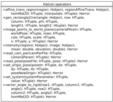
Halcon also provides a broad range of operators that are not related to any particular class, but available in C++ as static methods of the generic class
Halcon (see Figure 2.5). I am going to give a brief explanation of the most used operators, mainly used to decode the inner region of the E-Puck tags such as: vector angle to rigid(), gen rectangle2(), affine trans region(), and intensity(). The operator vector angle to rigid() computes and returns, in terms of rotation matrix and translation vector, a rigid affine transformation between two given points and corresponding orientations. The operator affine trans region() ap-plies an affine transformation to the given region and returns the transformed region. The operator intensity() calculates the mean and deviation of grey val-ues within the input region. The operator gen rectangle2() simply creates an oriented rectangle.
The rest of the operators are used for camera setting or camera view re-lated operation. They are: read cam par(), read pose(), set origin pose(), and image points to world plane(). The operators read cam par() and read pose() read from file the internal camera parameters and the camera pose respectively. The operator set origin pose() translates the origin of the 3D pose by a given vector. It is used to correct the real world coordinates of the robots, that are originally imprecise due to a perspective error. In fact, while the height of the cameras in the camera pose is the distance between the camera and the floor, the markers created for detection are placed on top robots. To compensate this error it is necessary to translate the camera pose on the z-axis for the height of the robots. The operator image points to world plane() transform a position in the image to a position in a real world coordinate system. This is used to have the position of the robots inside the arena. One last generic operator is set system() and allows to change many Halcon parameters.
Figure 2.6: QFile class diagram.
Although the ATS API Layer does not need any graphical library, it exploits the QT library for parsing the XML configuration file. The QT classes used for XML file parsing are QFile, QIODevice, QDomDocument, QDomElement and QString. QFile acquires a file given the file name (See Figure 2.6). QT allows to call some utility methods on a QFile object such as exists(), and open(). QIODevice class provides a public flag type called OpenMode that lists all the possible modes for file opening. QDomDocument class extends QDomNode with the ability to set the content of the file to the QDomDocument object (see Figure 2.7). QDomElement inherits as well from QDomNode class and represents a tag of the XML file. QString is simply a QT wrapper for the string type.
The QT library is used for graphical purpose in the application layer. In particular, the GUI package exploits a set of QT classes to build the user
in-Figure 2.7: QDom classes diagram.
terface of the viewer. The basic component of the QT GUI framework is the widget, and all the GUI components inherit from the class QWidget. The ap-plication main window itself extends QWidget class. The arena viewer main window inherits form QMainWindow to access all the QT window framework features such as menus, toolbars, labels and text areas. Figure 2.8 shows the QT classes used for the arena viewer and their most useful methods.
Figure 2.8: QT GUI elements class diagram. The principal classes QWidget and QMainWindow are highlighted.
2.2
Arena Tracking System API Layer
Figure 2.9: Core package class diagram. The principal classes are highlighted. As stated above, the Arena Tracking System API layer provides a set of functionalities tailored for tracking purpose. The layer is divided into two pack-ages called Core and Tracking (see Figure 2.3). The package Core contains all the basic data structures and provides all the needed interfaces to access them. The data types include the detected elements, the state of a single camera scope, the state of the entire arena space, the representation of the acquired images, plus a resource manager class that parses an XML configuration file and creates the specific image grabber, tracker, and camera (see Figure 2.9 and 2.10). The main class in the Core package is ArenaState, that represents the state of the experiment at a given timestep, i.e. the position and orientation, in the im-age and in the real world, of every detected robot in the arena. The detected robot is modelled by the class ArenaElement, and it is represented by its own robot ID, its position and orientation in the image and in the real world. The list of ArenaElements is given by ArenaState with the method GetArenaEle-ments(). Alternatively, ATS offers the possibility to get the detected robots under a specific camera, by requesting access to the camera with the method GetCameraState().
The package Tracking includes the single camera tracker, the entire arena tracker, and the interfaces apt to access several image grabbers, trackers and camera views, generated at runtime through a specific factory (see Figure 2.11).
Figure 2.10: Core package class diagram. The principal classes are highlighted.
The class ArenaStateTracker is able to create a new updated instance of Are-naState with the method GetAreAre-naState(). AreAre-naStateTracker is a manager for one or more CamerStateTracker, to which the GetArenaState() signal is prop-agated with GetCameraState(). Each CameraStateTracker is associated to an image source and the operators to detect the robots in the image. The Cam-eraStateTracker is composed by an ImageGrabber that encapsulates the logic to configure an image source and acquire an image, an ImageTracker that is responsible for detecting the robots in the acquired image, and a CameraView whose job is to convert the image position of the detected robots into the coor-dinates of a world reference system, given the internal and external parameters of the specific camera.
2.2.1
Detection and optimisation
As previously mentioned, the instance of ArenaStateTracker applies detection and decoding operators on the input image at every timestep. In order to spot and identify the robots navigating in the arena, the Arena Tracking System uses a type of marker that allows easy detection and decoding even when the image is relatively small. The markers encode the direction of navigation and the ID of the robot at once. Figure 2.12 shows an example of E-Puck marker. The external black arrow indicates the navigation direction, whereas the internal square matrix encodes the robot ID in binary notation, where black squares encode ”0” and white squares encode ”1”. The rising power order of the bits goes from left to right, from top to bottom. Each time the detection step is performed, every frame acquired by the ArenaStateTracker is scanned for occurrences of the marker. Each time a marker is detected, the inner matrix is decoded and converted to an ID.
Figure 2.11: Tracking package class diagram. The principal classes are high-lighted.
Markers detection is a very time consuming operation due to the high reso-lution of the cameras mounted in the arena (i.e., 1620 × 1220 pixels). Although the dedicated machine on which the Arena Tracking System is installed consists of 16 cores, and considered that Halcon operators can be parallelised on those cores, the marker detection on a single image takes on average over 100 ms. In multi camera experiments, the total average tracking time for one frame is the detection time multiplied by the number of cameras used. In a word, average tracking time breaks the requirement of good time resolution settled by the necessity to have real time virtual sensor data and seamless ARGoS integra-tion. It had been empirically proven that 100 ms is a good timestep period for ARGoS. To achieve effectiveness in the integration with ARGoS, the average tracking time per timestep must be around 100 ms. Which is true only for the single camera scenario. Therefore, optimisation in the image processing is needed. Scaling the images is not a viable option because the tiny squares of the markers are represented by only four pixels in the full definition image. A more appropriate solution is to implement an optimisation heuristic that processes the whole image, or set of images, only at a certain periodic timestep, called
Figure 2.12: On the left: example of E-Puck marker. On the right: markers applied on E-Pucks during an experiment.
Figure 2.13: On the left: the image domain processed in a keyframe. On the right: the image domain processed in a optimised frame.
keyframe. In the timesteps between two keyframes, the detection is performed only in the neighbourhood of a previously detected marker (see Figure 2.13). The size of the neighbourhood and the keyframe period are parameters that the researcher is able to set in the XML experiment configuration file.
This technique is consistent under the hypothesis that the robots move at a given maximum speed and therefore the maximum distance covered in 100 ms is easily computable. The periodic keyframe helps recovering the robots that may be lost by the ATS during the experiment. In fact, experimental data demonstrate that the reliability of the ATS on markers detection is constrained to keyframe period and neighbourhood size. Table 2.1 shows the number of detected robots for different configuration of the parameters keyframe period and neighbourhood size.
ATS marker detection reliability
Keyframe period (timesteps) Neighbourhood size (cm) Mean Median
1 – 19.25725 20
5 30 19.05596 19
5 11 19.06481 19
5 10 19.02939 19
9 11 19.01369 19
Table 2.1: ATS marker detection reliability in an experiment with a set of 20 robots.
The experiments are carried out with a set of 20 robots. Table 2.1 and Fig-ure 2.15 show that the system is more reliable for lower keyframe period and higher neighbourhood size. Figure 2.14 demonstrate that lowering the keyframe period and raising the neighbourhood size negatively affects efficiency. The researcher is responsible of settling the trade-off between time efficiency and detection reliability acting on the two parameters in the XML experiment con-figuration file.
2.2.2
Configuration
Two other important classes of the ATS API layer are ResouceManager and ExperimentManager (see Figure 2.16 and 2.17). ResourceManager is respon-sible for declaring the set of resources that a researcher wishes to employ for image acquisition and marker detection, while ExperimentManger is delegated for configuring the tracking session. Instances of these classes are meant to load an XML configuration file and to create the instances of the appropriate re-sources. In particular, the ResouceManager loads and instantiate the contents of the resources XML configuration file, the ExperimentManager creates the ob-jects described in the experiment XML configuration file. The resources XML file contains the definition and the parameters of cameras, detectors and image transformations available for the session. Each of these elements are mapped to a unique ID, that can be used in the configuration file to refer the resource.
The XML tree of the resource configuration file contains a root node, called arena tracking system, and three children nodes: grabbers, trackers, and cam-eras. The grabbers node contains the definition of every possible image source available in the experiment. It can be either a camera or directory of images. For each grabber of type camera, in the cameras section must be added a node called camera that contains the path to the camera calibration files. Also, for each grabber of type camera a set of parameters is defined. The camera param-eters in the resource configuration files are particularly useful for the researcher to change the brightness of the acquired images. In fact, quite often the bright-ness of the environment is constrained to some experiment requirement. For example, when the experiment requires a special light source or the coloured LEDs of the robots, the light of the environment must be dimmed to avoid in-terference. A semi dark environment prevents the tracking system to detect and decode correctly all the markers. Acting on the camera parameters allows the acquisition of clearer images and therefore a more efficient markers detection and decoding. The parameters involved with the brightness of the image are exposure time abs and gain raw. Raising the gain leads to brighter but more noisy images. In turn, exposure time increases proportionally to the risk to have blurred markers due to the movement of the robots. In the trackers section all the available trackers are listed in nodes called tracker. A parameter that the researcher might find useful here is robot height. This parameter allows the re-searcher to reuse the same set of markers on robots of different heigh, provided that in the same experiment the set of robots is homogeneous.
The ExperimentManager is instead used to read the experiment XML config-uration file that describes the configconfig-uration of the ArenaStateTracker in terms of its components. To configure an instance of ArenaStateTracker, the researcher only needs to specify in the XML file how many CameraStateTracker are part of the ArenaStateTracker and, for each of them, specify the resources they should
use calling them by their unique ID.
An example of XML tree for an experiment configuration file includes a root node called arena tracking, and two children nodes: arena state tracker and experiment record. The arena state tracker node includes three attributes and a collection of nodes called camera state tracker, one for each grabber employed in the experiment. The camera state tracker must include the specification of the grabber, a corresponding camera view if the grabber is of type camera, and the tracker. Back to the arena state tracker node, the attribute server port defines the port to which the ATS Server is bound, in case the researcher wants to use the ATS this way (see section 2.3.2). The attributes opt key frame period and opt square size are optimisation parameters (see section 2.2.1). The former defines the period in timesteps of the key frame occurrence, the latter is the dimension in centimetres of the side of the square that forms the neighbourhood around the formerly detected markers, on which the image domain is cropped.
Figure 2.14: ATS marker detection efficiency in ms. The x-axis values encode the keyframe period an the neighbourhood size divided by an underscore. The y-axis shows the time of each timestep in ms. The red line at 100 ms is a required upper bound for efficiency performances. The blue line at 25 ms is an ideal upper bound that allows a four camera experiment to meet the requirement of 100 ms per timestep. The red points represent the average computation time for each combination of keyframe period and neighbourhood size.
Figure 2.16: ResourceManager class diagram.
2.3
Arena Tracking System Application Layer
As stated earlier, there are two ways to use the ATS. One is to simply monitor and record the real time evolution of the experiment on all the cameras involved, manually controlling the beginning and the end of the video. For this purpose, an application called Viewer has been created. The Viewer usage do not involve any simulator of virtual sensing technology, it is only a tool to help carrying out traditional robotic experiments. The second provided usage hits the focus of the thesis and enables virtual sensing. This usage allows the researcher to monitor and control the execution of the experiment through the robotic swarm simula-tor ARGoS, opening a wide range of potential application already mentioned. For this purpose, the ATS Server has been implemented to communicate with a client built ad-hoc within ARGoS (see section 3.3.1).
In this section, the two applications will be presented in detail.
2.3.1
Arena Tracking System Viewer
Figure 2.18: Screenshot of the Viewer’s GUI.
The Arena Tracking System Viewer (ATS-V) is an application that allows a researcher to visualise and record the progress of the experiment through the images of the active cameras. The ATS-V needs a resource file and a config-uration file as argument to set up the desired view. The tool supports any possible subset of cameras among those specified in the resources file, and lets the researcher start and stop the visualisation of the images. The ATS-V also
allows to store the frames and record the whole experiment for further elabo-ration. For example, the researcher may like making a video of the experiment or tracking the robots offline, using a file grabber instead of a camera grabber. The recording of the images must be enabled in the experiment configuration file in order to be effective in the ATS-V application.
The viewer’s GUI is composed of three main parts: the visual panel, the control panel, and the informative panel (see Figure 2.18). The visual panel is a window in which all the cameras stream is displayed according to their position in the camera grid in the arena. To better recognise the camera in the grid, each view reports its camera ID and tracker ID. The control panel disposes the buttons that the researcher can use to start and stop the tracking session. The recording button is shown only for completeness, but its status is bound to the corresponding attribute record image in the experiment XML configuration file. The refresh of the visual panel heavily affects the tracking performance. The refresh toggle button allows the researcher to enable or disable the image refresh in order to gain in terms of performance.
The informative panel provides information about the status of the experi-ment, such as enabled or disabled image recording, current experiment run num-ber and current timestep. The function associated to the run button can be set in the experiment configuration file with the attribute change root directory on start. If the attribute is set to true, each run is a session between two consecutive start and stop. Otherwise, the run will be only one, but with the possibility to sus-pend and resume the tracking, and therefore the recording if enabled.
2.3.2
Arena Tracking System Server
The Arena Tracking System Server (ATS-S) application is the interface between the ATS and ARGoS. The application must be launched with the path to a resources configuration file and an experiment configuration file as arguments. ATS-S binds a TCP socket on the two network interfaces of the ATS machine to the port specified in the attribute server port in the experiment XML con-figuration file. The client within ARGoS must know the address and port on which the ATS-S is waiting to open a TCP connection (see Figure 2.19). After binding, the server enters its main loop. The loop consists of two simple steps: waiting for a connection and enter an inner loop that repeatedly executes com-mands sent by the client. The inner loop ends when the client disconnects, then the control returns to the main loop that start again waiting for a new connec-tion. The commands that the ATS-S is able to detect and execute are three: start experiment, stop experiment and one shot. The first two commands begin and conclude respectively a tracking session, while the one shot command per-forms tracking only on one frame and returns the arena state only once, without incrementing the timestep counter. The command one shot is particularly use-ful at the beginning of the experiment to initialise the arena state data structure before actually starting the experiment.
SOCKET BIND SERVER START WAITING FOR CONNECTION CLIENT CONNECTED WAITING FOR COMMAND COMMAND RECEIVED EXECUTE COMMAND INNER LOOP CLIENT DISCONNECTION MAIN LOOP STOP EXPERIMENT COMMAND
Chapter 3
Arena Tracking System
Virtual Sensing Plugin
This chapter discusses the Arena Tracking System Virtual Sensing Plugin, or ATS-VSP, the tool that implements all the features needed to provide virtual sensing technology to a swarm of E-Pucks. Among other components, the ATS-VSP contains the Arena Tracking System Physics Engine, or ATS-PE, the core of the virtual sensor design, and also the link between simulation and reality.
The ATS-VSP works within ARGoS as a physics engine plugin. To better understand what a physics engine really is in ARGoS, I am going to give the reader a quick overview of the robotic swarm simulator, why I used it, and what are the advantages of integrating the Arena Tracking System in it. The other components included in the ATS-VSP are the networking components for com-munication with ATS-C and E-Puck swarm, and the virtual sensor bare bones architecture. These components will be described thoroughly in Section 3.3 and Sensor 3.4, covering the simulator and real robot module respectively.
3.1
ARGoS overview
ARGoS [17] is a modular, threaded, engine simulator for multi-robot systems developed at the IRIDIA lab. ARGoS achieves both efficiency and flexibility through parallel design and modularity.
In ARGoS, all the main architectural components are designed as selectable modules, or plugins. The advantage of modularity is that each selected mod-ule is loaded at runtime, allocating the resources for the interested aspects of simulation and neglecting unneeded computation. Modularity also eases flexi-bility. In fact, the plugin structure allows the researcher to modify, diversify and create modules. In ARGoS, all kind of resources are plugins, including robot control software, sensors, actuators, physics engines, visualisations and robots. Several implementations of the same plugin are possible, and usually they differ for accuracy and computational cost. Thanks to this kind of tunable accuracy, the researcher is able to choose the precision of any aspect of the simulation, improving efficiency and flexibility at once.
To clarify the modular architecture of ARGoS, let’s exemplify the simulated 3D space. In ARGoS, the simulated 3D space is a collection of data structures,
Figure 3.1: Example of ARGoS’s entity hierarchy.
called entities, that contains the complete state of the simulation, i.e., the state of each object involved. An object can be a robot, an obstacle or any other item. To represent different kinds of objects, ARGoS offers several types of entities, where each of them stores a particular aspect of the simulation. Entities can be combined to each other, creating composable entities able to model more complex objects. Entities can be also created brand new extending the basic entity class. The state of a simple object can be stored in a simple entity like positional entity, that contains only the position and orientation of the object. For a wheeled robot, the sole positional entity is not enough. In fact, its state must be completed by an entity that stores the speed of the wheels, called in ARGoS wheeled entity, and a controllable entity that keeps a reference to the user defined control software and to the robot’s sensor and actuators.
Entity types are organised in hierarchy. For example, Figure 3.1 shows that the embodied entity is an extension of the positional entity that adds a 3D bounding box for the referred object. Robots’ entities are themselves extensions of composable entities since their state incorporates many aspects. Figure 3.2
Figure 3.2: E-Puck entity class diagram.
depicts the types of the entities that compose the E-Puck entity. Such a design is essential to provide flexibility and at the same time promote code reusability and avoid redundancy.
Sensors and actuators are plugins that access the state of the simulated 3D space. Sensors access the space in read-only mode, while actuators are allowed to modify it. More precisely, every sensor and actuator is designed to only access the space entities involved in the specific measurement. The advantages of bounding sensors and actuators to specific entities affect both flexibility and efficiency. Flexibility is enhanced because tailoring sensors and actuators plugins to specific components instead of the whole robot often leads to a generic robot independent plugin design, that can be reused with different types of robots. Another benefit to flexibility is that robots can be built easily and quickly incorporating existing components, guaranteeing that all the sensors and actuators targeted for those components will work without modifications. In the matter of efficiency, the robot components associated to sensors or actuators that are not employed in a simulation do not need to be updated, preventing unnecessary waste of computational resources.
Physics engines are the components in charge of calculating the positions of the robots according to a set of consistent physical laws. In ARGoS, physics engines are plugins allowed to update the embodied entities status. ARGoS provides four kinds of physics engines: a 3D-dynamics engine based on Open Dynamics Engine (ODE), a 3D particle engine, a 2D-dynamics engine based on the open source physics engine library Chipmunk [1], and a 2D-kinematics engine. The researcher can choose the appropriate engine according to the kind of simulation he/she is carrying out. In addiction, ARGoS allows to split the 3D space assigning to each subspace a different physics engine. This feature permits a very fine grain of control of the 3D space. Furthermore, using several physics engines boosts the simulator performances because, thanks to ARGoS
multi-threading, the computation of different engines is parallelised.
Robot controllers are plugins that contain the control software of the robots. One of the most powerful features of ARGoS is the possibility to test a partic-ular controller on real robots after the simulation without changing the control software code. This feature is very important because the researcher is able to compare the performances of the same controller in simulation and reality and can identify more precisely the source of possible discordances. ARGoS robot control software is written in C++, however, robots used for swarm robotics usually embed a low-end processor. Thus, before migrating the code from the simulator to the robots it is necessary to recompile the control software for the particular architecture. Apart from the recompilation, the control software does not need any refactoring. To guarantee the portability of the code, the controller designer relies on control interfaces to access the sensors and actuators. The control interfaces must be installed on the simulator side and on all the robot architectures, and must be implemented by all the sensors and actuators of the simulator module and the real robot modules.
Visualisations are plugins that read the state of the simulated 3D space and create the visual representation of it. At the moment three kinds of visual-isations are available in ARGoS. Just like any other plugin component, the researcher can select the most appropriate visualisation according to the goal of the simulation. For high quality graphics ARGoS provides a rendering engine based on ray-tracing. For an interactive GUI the researcher can choose a plugin based on OpenGL. If the goal of the simulation is interaction with data analysis programs rather than visualisation, a text-based visualisation plugin is available to avoid useless graphical computation.
It is very hard to cover all the possible use cases for a general purpose sim-ulator like ARGoS, without making the tool unmanageable under the usability and maintainability point of view. ARGoS design choice to grant flexibility, without burden the tool’s complexity, is to provide user-defined function hooks in strategic points of the simulation loop. The user is able to write the so called loop functions, adding custom functionalities to be executed before or after the control step. A loop function can access and modify the whole simulation. In fact, the user is allowed to store data for later analysis, calculate statistics, and even create a new dynamic in the simulation by adding or remove objects in the 3D space.
Deep modularity and flexibility makes ARGoS suitable for execution on real robots, upon appropriate compilation. The components intended for the robots must be implemented accordingly and specifically compiled for the particular purpose. ARGoS code structure can be seen under two perspectives: deploy-ment and source code. The deploydeploy-ment point of view groups the components according to their target, that can be simulator, robots, or both. This clas-sification consists of three main areas: control interfaces, simulation modules and real robot modules. Figure 3.3 shows the structures and the contents of the different areas. In the control interface area is located the software needed both on simulator and on the robots, typically control interfaces for sensors and actuators. In the simulation area goes the whole set of components used by the simulator and by the simulated robots: simulated sensors and actuators, space entities, physics engines, and visualisations. The real robot area contains the code specifically implemented for the real robots. Typically the real robot area reflects the structure of the simulated robots part in the simulator area.
ARGoS PLUGIN REAL ROBOT SIMULATION E-PUCK FOOT-BOT GENERIC ENTITIES E-PUCK FOOT-BOT GENERIC ROBOTS E-PUCK FOOT-BOT GENERIC SENSORS ACTUATORS PHYSICS ENGINES SIMULATOR CONTROL INTERFACE
Figure 3.3: ARGoS deployment areas.
The components in this area are sensors and actuators and any other specific component that can execute on the real robots.
The source code perspective reflects the source code tree organisation. This perspective groups the components according to their logical function rather than the target. Figure 3.4 gives a representation of the source code tree, dif-ferentiating the distinct target areas with colours.
From the two classifications emerges that the robots section is divided into more subsections including generic, e-puck, and foot-bot. The generic section contains sensors and actuators tied to space entities that are so generic to be employed on any type of robot. To implement any robot specific sensor or actuator it is necessary to create the respective robot directory in the source code tree and implement the components for the desired target: common interface, simulator, or real robot. ARGoS currently provides the simulation and real robot modules for E-Puck robots and the simulation module for Footbot robots. To execute the code on real robots, the dedicate modules must be compiled for the specific robot architecture. In this case the built output comprehend the green and yellow areas of Figure 3.3, while when compiling for simulation target the resulting built output corresponds to the blue and yellow areas.
The ARGoS settings must be configured in an XML configuration file. The configuration file specifies the set up of the whole experiment, it contains infor-mation about the arena, the robots, the physics engines and the loop functions. The same XML configuration file is used for launching both the ARGoS simu-lator and the real robots main, therefore it must be uploaded on all the robots together with the control software.
The general structure of the file is given by a root node called argos-configuration and six child nodes: framework, controllers, arena, physics engine, visualisation, and loop functions. The framework node specifies some internal parameters used by ARGoS core, such as the number of threads used for multi threading,