RICERCA DI SISTEMA ELETTRICO
Rapporto di dettaglio sulla progettazione e realizzazione del sistema di
purificazione dell’impianto LiFus6
P.Favuzza, A.Aiello, S.Mannori, M.Muzzarelli
Report RdS/2012/261
Agenzia nazionale per le nuove tecnologie, l’energia e lo sviluppo economico sostenibile
RAPPORTO DI DETTAGLIO SULLA PROGETTAZIONE E REALIZZAZIONE DEL SISTEMA DI PURIFICAZIONE DELL’IMPIANTO LIFUS6
P. Favuzza UTIS – CPM ENEA - FIRENZE
A. Aiello UTIS – PNIP ENEA - BRASIMONE
S. Mannori UTIS – PNIP ENEA - BRASIMONE
M. Muzzarelli UTVALAMB ENEA – BOLOGNA
Settembre 2012
Report Ricerca di Sistema Elettrico
Accordo di Programma Ministero dello Sviluppo Economico - ENEA Area: Governo, gestione e sviluppo del sistema elettrico nazionale
Progetto: 1.3.2 Fusione nucleare: Attività di fisica e tecnologia della fusione complementari a ITER Responsabile del Progetto: Aldo Pizzuto, ENEA
3
Content
Summary ... Errore. Il segnalibro non è definito. Introduction ... Errore. Il segnalibro non è definito. Description of the activity and results ... Errore. Il segnalibro non è definito.
1. Overview of Lifus 6 purification elements ... 6
2. The Cold Trap (CT) ... 7
3. The Hot Trap (HT) ... 9
4. The Resistivity Meter (RM) ...12
5. Off-line analysis of Lithium samples ...15
Conclusion ...17
References ...18
Summary
This document deals with the solutions employed for the purification system of Lifus 6, a plant devoted to corrosion tests in flowing liquid Lithium, whose operations are going to start the next year. Reducing significantly the concentration of non metals (C, O, H and N) solved in Lithium, which highly enhance its corrosive behavior, is the purpose of the purification.
The purification is performed through a Cold Trap, where the precipitation of the various binary non metals-Lithium compounds is promoted thanks to the reduction of the Temperature (200°C), and an Hot
Trap, filled with a Titanium sponge getter, where Nitrogen concentration in Lithium is further reduced,
thanks to the formation of a stable Titanium Nitride at 600°C.
The residual concentration of Nitrogen in Lithium is online monitored by the Resistivity Meter, thanks to the existence of a linear relation linking it to Lithium resistivity, and by an offline Lithium analysis procedure, based on the transformation of small amounts of Lithium taken from the plant at defined time spans into Ammonia: this procedure, even if more time and work consuming, has the advantage of an higher sensitivity and may be useful also for the calibration of the Resistivity Meter.
Both the Cold Trap and the Resistivity Meter are inserted into a secondary (purification) loop, which is characterized by a Lithium flow rate reduced to about 1% of Lifus 6 main loop, so to guarantee a sufficiently large residence time of Lithium through them and their best operative conditions.
The purification system so defined will permit to reduce C, O and N content below 10 wppm, while H content will be reduced to about 60 wppm; on the other hand, no existing device could permit to precisely quantify a so small H concentration, so the efficiency of a more pronounced purification could in no case be verified.
Introduction
Lifus 6, the revised version of Lifus 3, is a plant dedicated to the tests of flowing liquid Lithium, as a part of the study and development of the IFMIF facility (Broader Approach activities). ENEA is in charge of its realization and validation, in its research centre of Brasimone.
The plant is basically constituted by two parts: the main loop, directed to corrosion tests and compatibility studies between structural materials (particularly RAFM steels) and high temperature flowing liquid Lithium; the secondary loop, aimed at the purification of the circulating Lithium from solved non metals impurities (like C, O, H and N). There is a tight connection between the purposes of the two loops: the presence of non metals, in the form of anions solved by liquid Lithium, sure enough enhances the chemical corrosion mechanisms affecting the steels; particularly, N is considered to be the most upsetting one, mostly because of the formation of Li ternary Nitrides (Li3FeN2,..) [1,2]. For this reason, IFMIF requirements dictate that the weight content of each of the aforementioned elements doesn’t exceed 10 ppm.
This document deals with the solutions that will be adopted in order to purify as much as possible the Lithium circulating inside Lifus 6 plant, together with the procedures and the experimental setup to monitor the residual impurities content and their evolution with time. The solutions employed constitute the result of the research work done in ENEA during last years, also in collaboration with Nottingham University School of Chemistry, particularly with prof. Hubberstey. The design of the purification elements has been completely defined and some of them have been already constructed; their installation and commissioning is going to start; their validation is scheduled by the beginning of the next year.
1.
Overview of Lifus 6 purification elements
The purification of Lifus 6 plant will be performed according to the solution schematically drawn in figure 1. A dedicated purification loop (on the right side of the figure), will work in parallel with the main loop, holding both the Cold Trap (CT, par. 2) and the Resistivity Meter (RM, par. 4); the Hot Trap (HT, par. 3) will be put instead directly along the main Lifus 6 loop and will be coincident with the Lithium storage tank, from which the main loop is charged and discharged.
Figure 1: Schematic blocks diagram of Lifus 6 purification elements
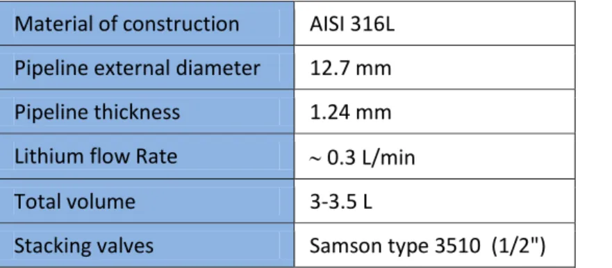
The main loop consists of an AISI 316L pipeline, having an inner diameter of 1 inch and a total volume of about 5 liters. A dedicated pump moves the liquid Lithium (T=350°C) at about 30 L/min throughout it. At point A, a stacking valve splits the Lithium in two branches, allowing a little fraction of the metal mass (about 1%) to enter the secondary loop; in point B, the partly purified metal, after passing through the Resistivity Meter and the Cold Trap, rejoins the larger Lithium mass into the primary loop. The purification loop features are defined in table 1.
Table 1: Purification loop main features Material of construction AISI 316L Pipeline external diameter 12.7 mm Pipeline thickness 1.24 mm Lithium flow Rate 0.3 L/min
Total volume 3-3.5 L
Stacking valves Samson type 3510 (1/2")
The flow rate of Lithium through the purification loop is not set by a dedicated pump, but it just results from the regulation of the entering valve and from the pressure drop originated by the elements of the
circuit, particularly by the Cold Trap; it is measured by a mini turbine flow-meter, entirely made in stainless steels. It is worth mentioning that the total volume of the circuit is dictated mainly by the Cold Trap volume, which is surely its largest element ( 3L).
2.
The Cold Trap (CT)
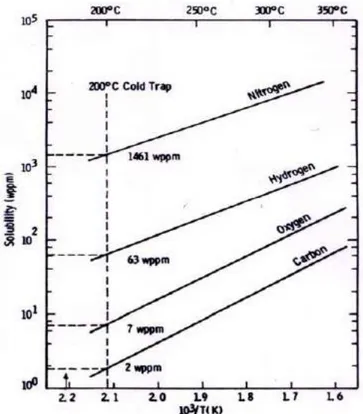
The purpose of the Cold Trap is to reduce non metallic impurities content, exploiting the precipitation phenomenon of their related binary compounds with Lithium. Since the solubility of these compounds increases with temperature, it’s clear that the lower the trap operating temperature, the more pronounced will be all the precipitation equilibria. Solid Lithium Carbides, Hydrides, Nitrides and Oxides will then accumulate inside the Cold Trap, until the remaining content in Lithium solution will match the solubility value at the trap temperature. Ideally the Cold Trap should be maintained just above the melting point of the metal so that the maximum amount of impurity could be removed. The working temperature needs anyway to be high enough to prevent solidification of the metal and plug formation. A temperature 20°C above the melting point of the metal is thought to be ideal in order to balance these two considerations. Therefore the minimum operating temperature of the trap should be 200°C. At this temperature, residual impurities maximum content will be 2 wppm for Carbon, 7 wppm for Oxygen, 63 wppm for Hydrogen and 1461 wppm for Nitrogen, as shown in figure 2 [3]. It appears that the Cold Trap will result particularly efficient for the removal of Carbon and Oxygen.
Figure 2: Solubility diagram of Lithium compounds
In order to achieve an efficient separation of the solid precipitates from Lithium solution, it’s important that coarse grains are obtained, instead of highly dispersed particles, which more hardly settle inside the trap. For this reason, the cooling of Lithium from 350°C to 200°C shall not be too fast, so to avoid a high local supersaturation, condition in which the nucleation (that is the birth of new precipitate grain) is faster than
the growth of the already formed grains [4]. Moreover, the solid precipitation and retention can be improved employing a knitted or woven stainless steel wire mesh inside the Cold Trap as a packing material. This evidence has been derived mainly from the experiences with liquid Sodium and from the related design of many different industrial reactor traps [5-8]. The mesh, characterized by a large surface area, provides anchorage sites for the nucleation of the solid particles and for their subsequent growth. Taking into account all these aspects, the design of the Cold Trap has been defined (see figure 3); the material of construction is AISI 316L.
Figure 3: design of the Cold Trap (all the dimension are expressed in mm)
The gettering volume is realized by disposing a high number (66) of Stainless Steel mesh sheets (MESH:60; wire diameter: 0.18 mm; hole length: 0.25 mm), parallel packed inside the body of the trap. The distance between the sheets is 3 mm: in this way the SS packing density results about 300 kg m-3.
Considering the internal volume is about 3L and the Lithium flow rate inside the trap is about 0.3 L/min, the residence time is fixed to about 10 min, which, borrowing Sodium experience, is believed to be a suitable time for an high purification efficiency (≥ 70% for each passage) [4-10].
The so defined purification procedure targets only about 1% of the total circulating Lithium in the unit time (only the Lithium flowing inside the purification loop). However, proceeding through iterative steps, it is possible to verify that statistically all the Lithium will pass through the trap (and will hence purified) in some hour.
3.
The Hot Trap (HT)
As stated in the previous section, the solubility of Nitrogen in Lithium is too high to succeed in reducing Nitrogen content at acceptable levels using the Cold Trap alone. To overcome this limit, an additional, different approach is employed. This is based on the exploitation of chemical reactions involving the Nitride anion and a metal different from Lithium, leading to the formation of a solid product. So, it is necessary that this additional metal (herein referred as “getter”) can come in contact with Lithium, hence with the Nitride solved in it: this condition is realized in the Nitrogen Trap.
In a Nitrogen Trap an insoluble getter is immersed in the liquid metal to collect the impurity. It works by the general equation:
L[X] + M L + MXn Liquid Solid Liquid Solid
The thermodynamic efficiency with which the getter M can remove the impurity X from the liquid metal L is dictated by the magnitude of the free energy change (G) associated with the above reaction: the more negative is the value of G, the more efficient the getter results. From the Ellingham diagram (figure 4), it can be seen that a variety of metals have the potential to act as a getter for Nitrogen.
Figure 4: Ellingham diagram (free energy diagram for Nitrides)
Comparing the advantages/disadvantages of many of the metals shown in figure 4 as well as of some of their binary alloys (like V-10%Ti) [11-16], ENEA has selected pure Titanium metal as getter material for the Nitrogen Trap, particularly the Titanium sponge (solid grains commercial product; d=2-12 mm; apparent density 0.55 g cm-3). This form can in fact simplify the incorporation inside the Trap and has the additional advantage of an increased surface area and therefore of a greater gettering potential, since more Titanium can be in contact with Lithium at any time. Clearly, the higher the temperature of the Trap, the less effective
the getter from a thermodynamic point of view. However, the rate at which gettering takes place, which involves the diffusion of a non-metal into the getter, is higher at higher temperatures and surface films have a less of an inhibiting effect. The chosen temperature compromise is 600°C, at which it is possible to reduce Nitrogen concentration in Lithium to 2 wppm [17]in some days [18].
Due to his relatively high temperature value, for comparison with the Cold Trap (200°C) and the other parts of Lifus 6 plant (350°C), Nitrogen Trap is referred to also as ‘Hot Trap’ (HT).
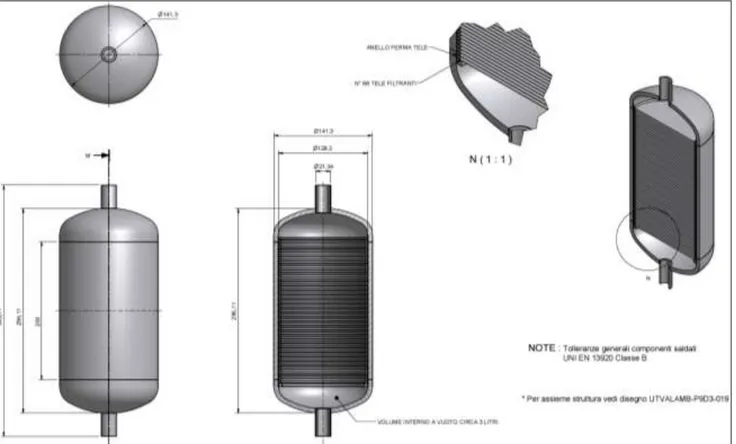
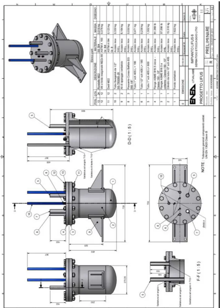
As stated in section 1, the Hot Trap will not be part of the dedicated purification loop, but it will be coincident with the Lithium storage tank, from which the main loop is charged and discharged. The design of this tank has been performed and it is shown in figure 5. It consists of:
an inlet pipe for its first filling with all the Lithium inventory from an external storage tank or container (6 in figure 5)
one pipe for the entering/exiting of the Lithium from the Trap to the main loop (5) 3 level sensors (8)
2 gas inlet/outlet (10), one for depressurizing the tank or filling it with Argon, the other used as a safety valve and for the measure of the pressure
1 emergency draining exit (7)
While the purification of Lithium is performed continuously for what concerns the CT, it is instead performed at discrete time steps, in static conditions, for what concerns the HT. The Li storage tank will be employed as the Hot Trap not only before charging all the Lithium (at the beginning of the operations), but each time the Nitrogen content has reached a too high value, as revealed by the impurities control procedures: in these cases, it is possible to stop the circulation of the metal, discharge it back in the storage tank, and give it time to react again with the Titanium getter.
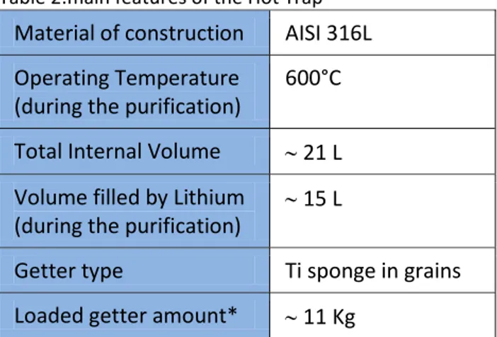
The Hot Trap features are summarized in table 2.
Table 2:main features of the Hot Trap Material of construction AISI 316L Operating Temperature
(during the purification)
600°C
Total Internal Volume 21 L Volume filled by Lithium
(during the purification)
15 L
Getter type Ti sponge in grains Loaded getter amount* 11 Kg
4.
The Resistivity Meter (RM)
A detailed description of the design of this device and its principle of functioning have been already reported in the document: “Sistemi di monitoraggio di fenomeni di cavitazione e di impurezze non
metalliche nel circuito litio liquido” – PAR 2010 - RDS 381.
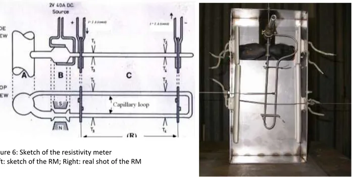
Briefly, the RM, shown in figure 6 both as a sketch and as a real shot, is a device able to online monitor the electric resistivity () of the flowing Lithium. It was developed at the University of Nottingham in collaboration with ENEA Brasimone and relies on the variation of the metal resistivity produced by the dissolved anions [19,20]: the higher the impurities concentration in Lithium, the higher the resistivity. Considering that Nitride ion is much more soluble in Lithium than other anions, it’s possible to almost entirely ascribe the variation of to N, which, as already stated, is the most corrosion affecting non metal. As shown in figure 1, the RM is linked to the purification loop of Lifus 6 upstream of the Cold Trap: in this way, the Lithium flowing through the RM is expected to be the less purified one and the result of the measurement is surely not underestimating the impurity content of Lifus 6.
Figure 6: Sketch of the resistivity meter
Left: sketch of the RM; Right: real shot of the RM
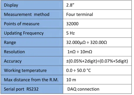
A nano-ohm-meter is employed for the acquisition of the resistance values, through a standard four terminals method. It is connected by means of a serial port (RS232) to a data logger interfaced to a PC. The main characteristics of the instrument are summarized in table 3. Taking into account them and the features of the other electrical parts, and considering also that the measured resistance values fall in the range of 5-15 mΩ (see figure 7), it is possible to calculate the true sensitivity of the measure as ±1 µΩ and the true accuracy as ±5 µΩ.
Since it is possible to quantify only the total electric resistance exerted by the capillary section (Rtot), if we want to know the real value of resistance of the Lithium flowing inside it (RLi), it is necessary to already know the resistance of the capillary alone, that is the resistance of the capillary when empty (Rcell). Through the expression for parallel resistances:
RLi = (Rcell x Rtot) / (Rcell – Rtot)
is therefore possible, once measured the resistance of the empty capillary, to obtain the resistance of the Lithium alone. Figure 7 shows the experimental values of Rcell and Rtot and the calculated value of RLi as a function of temperature, as obtained by the University of Nottingham [21].
Table 3: Main characteristics of the nano-ohm-meter
Display 2.8”
Measurement method Four terminal Points of measure 32000 Updating Frequency 5 Hz Range 32.000µΩ ÷ 320.00Ω Resolution 1nΩ ÷ 10mΩ Accuracy ±(0.05%+2digit)÷(0.07%+5digit) Working temperature 0.0 ÷ 50.0 °C
Max distance from the R.M. 10 m
Serial port RS232 DAQ connection
Figure 7: Resistance of the empty meter (Rcell), of the meter full of Lithium (Rtot) and of the Lithium alone (RLi) as a
function of Temperature
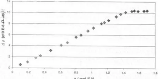
Resistivity-composition isotherms for solutions of Nitrogen in liquid Lithium have been determined at 14 temperatures in the range 200°-450°C. One of them (at 400°C) is shown, as an example, in figure 8. All the isotherms show that for very diluted solutions (up to a concentration designated as ‘minimum x’) the resistivity increases with a slowly increasing gradient, while, for more concentrated solutions, it increases linearly, up to the saturation of the solution (concentration designated as ‘maximum x’), beyond which it remains constant. In the linear region, which is the dominant feature of the isotherm and where the following relation holds:
is hence possible to obtain the value of x (atomic % of Nitrogen content) once the value of Li has been measured and A and B parameters have been evaluated from the fitting of experimental data.
Figure 8: Resistivity-composition isotherm for solutions of Nitrogen in liquid Lithium at 400°C. The resistivity variation () is related to the resistivity of pure Lithium (with no Nitrogen)
Values of A and B and the relevant concentration ranges (‘minimum x’, ‘maximum x’), as determined by Nottingham University calibration, are given in Table 4 at selected temperatures: it is possible to see that all the parameters vary with T, even if not to a great extent, the sensitivity of the resistivity meter (B) increasing a little with T.
Table 4: fitting parameters from the vs x experimental curves. These values refer to the calibration performed by Nottingham University Temperature/ oC 200 250 300 350 400 450 108 A/m 24.06 25.67 27.17 28.47 29.61 30.39 108 B /m (mol % N) 5.7 6.2 6.5 6.8 7.0 7.2 Mimimum x / mol % N 0.03 0.03 0.05 0.15 0.3 0.6 Maximum x / mol % N 0.07 0.19 0.41 0.80 1.45 2.77
From the existence of a minimum value of resistivity variation that can be measured, as derived from the minimum actual variation of resistance that can be registered with the employed instrumentation, follows the existence of a minimum value for the detectable variation of the Nitrogen concentration in Lithium at each temperature. Taking into account that the true sensitivity of the nano-ohm-meter is ±1 µΩ, that the ±0.5°C uncertainty in the temperature control translates, according to the equation reported in the top curve of figure 7, into and additional ±8 µΩ fluctuation, and considering the geometrical factor of the RM capillary, it is possible to calculate the minimum significant variation in the Lithium resistivity as about 0.18 nΩ m. Dividing this value by the B values in table 4, it is possible to estimate the minimum detectable variation of Nitrogen concentration in Lithium at each temperature, i.e. the sensitivity of the measurement apparatus respect to Nitrogen content (see table 5). At 350°C, which is Lifus 6 and RM operative temperature, this value is 53 wppm.
Table 5: minimum detectable variation of Nitrogen concentrations in Lithium (absolute values) at various temperatures (in case of a minimum detectable resistivity variation of 0.18 n m)
Temperature / °C 200 250 300 350 400 450
Minimum detectable N variation / wppm 63 58 55 53 51 50
In no practical experimental condition is therefore possible for the Resistivity Meter to guarantee that the flowing Lithium satisfies IFMIF high purity requirements (Nitrogen <10 wppm). The device can anyway be useful to indicate the reaching of an high impurities threshold, as an alarm indicator.
Experiments with insoluble getters confirmed the effectiveness of the meter in monitoring Nitrogen concentration in liquid Lithium. In all cases (both employing Cr and V as getter), the resistivity value measured by the instrument quickly decreased as soon as the introduced getter, adsorbing Nitrogen, was able to lower its concentration below the saturation value; conversely, when new Nitrogen was added more to the liquid metal solution, so to exceed the adsorption capacity of the already present getter, measured resistivity quickly came back to an higher value.
5.
Off-line analysis of Lithium samples
In order to overcome the limits of the Resistivity Meter, which is not chemically specific and shows a limited sensitivity to non metals concentration, an offline Lithium analysis is also employed. This procedure entails to take a Lithium sample from the plant using a small metallic container (V = 10 mL) linked to the purification loop by a trivial volume duct. It is mandatory, in this phase, as well as during the following analysis procedure, to avoid any contact between the Lithium and the air.
The Lithium taken from the plant is analyzed for its Nitride content. For this reason, operating under an Argon atmosphere in a glove box, it is transferred into a three necks glass vessel and let to react with water [22,23], added slowly and paying attention to the possible violence of the reactions. The reactions involved are:
2 Li + 2H2O 2 LiOH + H2
Li3N + 3H2O 3 LiOH + NH3
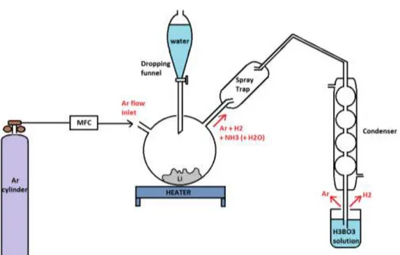
A part from the formation of large H2 volumes, the important aspect is that all the Nitride is converted into Ammonia. Under an Argon flow, the Ammonia is distilled away and then quantitatively collected into a water solution of Boric Acid in excess (transforming into the stable NH4+ ion). The apparatus employed for this transformation, which is going to be arranged in a ENEA lab close to Lifus 6 room, will be similar to the one depicted in figure 9. The NH4+ concentration in the final solution will be then evaluated by HPLC (Ionic Chromatography), a rather fast and simple determination, able to measure down to few wppm of starting Nitrogen in Lithium and with a relative precision of some %. The HPLC analysis will be performed by the
Analytical Chemistry Department of the University of Firenze (I).
Standard materials containing exactly known amount of Nitrogen will be used, submitting them to all the steps of the procedure, in order to preventively assess the validity of the method and allow the calibration of the instrumental answer.
Conclusion
The purification system of Lifus 6 plant has been completely defined and the design of its element performed.
Lifus 6 will comprise a secondary loop, explicitly dedicated to the purification operations, where the metal flow rate will be reduced to about 1% of the main loop ( 0.3 L/min) and containing both the Cold Trap and the Resistivity Meter. The reduction of Lithium flow rate (and hence the existence of the secondary loop) is necessary in order to fix the residence time of Lithium inside the Cold Trap to 10 minutes, which is required for an high Trap efficiency; otherwise, putting the Cold Trap directly inside the main loop would not permit to obtain the desired Lithium linear rate in the target section (15 m/s). In order to enhance the precipitation equilibria which take place in its interior, avoiding any risk of Lithium solidification, the Cold Trap temperature is set at 200°C. At this temperature, it will be possible to practically remove both the Carbon and Oxygen impurities, while Hydrogen and Nitrogen contents will be respectively reduced to 63 wppm and 1461 wppm.
An Hot Trap, operating at 600°C and containing a Titanium sponge getter, will also be employed, aiming at reducing the still high value of Nitrogen concentration down to 2 wppm. The HT will be put directly along the main Lifus 6 loop and will be coincident with the Lithium storage tank: the purification will be here performed at discrete time steps, in static conditions (for some days). The Li storage tank will be employed as the Hot Trap before charging all the Lithium (at the beginning of the operations) and every time the Nitrogen content will reach a too high value: in these cases, the circulation will be stopped and the metal will be discharged back in the storage tank, giving it time to react again with the Titanium getter.
The efficiency of the Li purification from N will be estimated by the Resistivity Meter, a device installed in the purification loop, able to online provide the measure of the resistivity of the Lithium, which can be linked, through a linear relation, to N concentration. Since the RM suffers from a limited sensitivity, an offline Lithium analysis will be adopted too, entailing to sample Lithium from Lifus 6, before and at defined time spans during the corrosion tests and submit it to a specific chemical reaction. This procedure will be more time and work consuming, but will permit to determine down to few wppm of Nitrogen in the sampled Lithium, with a relative precision of some %; moreover, it will permit to calibrate the RM, disposing of a Lithium with a known content of Nitrogen.
Other possible online analysis techniques are still under investigation, which could provide both a fast and accurate evaluation of very small impurities concentration in circulating Lithium.
References
1. K. Natesan, “Influence of nonmetallic elements on the compatibility of structural materials with liquid alkali metals”, Journal of Nuclear Materials, 115 (1983), 251-262
2. O.K. Chopra and D.L. Smith, “Influence of Temperature and Lithium purity on corrosion of ferrous alloys in a flowing lithium environment” Journal of Nuclear Materials, 141-143 (1986), 584-591
3. M.G. Down, Proc. 2nd. Int. Conf. Liquid Metals Technology and Energy Production, Richland, Wash., Vol. 2 (1980), 14-16
4. B.R. Grundy “Experimental characterization of sodium cold traps and modelling of their behaviour” Proc. Int. Conf. on Liq. Met. Tech. in En. Prod., Champion, (1976), 650
5. R.B. Hinze, Chemical Engineering Progress Symposium Series: Nuclear Engineering Part XXI No 104, Vol. 66, 94-106
6. J.W. Mausteller, F. Tepper and S.J. Rodgers “Alkali metal handling and systems operating techniques” ANS, Gordon & Breach, (1967), 39-76
7. R.W. Dickinson “Liquid metals handbook – Sodium and NaK Supplement. Chapter 6, Purification” O.J. Foust Editor, June 30, 1967
8. K.R. Kim, J.Y. Jeong, K. C. Jeong, S. W. Kwon and S.T. Hwang, “J. Industrial and Engineering Chemistry (Seoul)”, Vol. 4 (1998), 113-121
9. M.M. Osterhout, “Control of oxygen, hydrogen and tritium in sodium systems at Experimental Breeder Reactor II” – UAC – 41069
10. W.H. Bruggeman, “Purity Control in Sodium-cooled Reactor Systems” A.I.Ch.E. Journal, Vol 2, N°2 (1956), 153
11. Y.Kato, K.Watanabe and T.Kondo, “J.Nucl. Mater.”, 191-194 (1992), 1428
12. J.R. Weston, F.W. Calaway, R.M. Yonco, and V. A. Maroni, Proc. 2nd. Int. Conf. “Liquid Metals Technology and Energy Production”, Richland, Wash., Vol. 2 (1980), 20-1
13. M. G. Barker, P. Hubberstey, A. T. Dadd and S. A. Frankham, “J. Nucl Mater.”, 114 (1983), 143-149 14. P. Hubberstey and P. G. Roberts “J. Nucl Mater.”, 155-157 (1988), 694-697
15. T.Sakurai, T. Yoneoka, S. Tanaka, A. Suzuki and T. Muroga, “J. Nucl. Mater.”, 307-311 (2002), 1380-1385 16. H. Nakamura et al., “Present Status of the Liquid Lithium Target Facility in the International Fusion
Materials Irradiation Facility (IFMIF)”, paper ID O-463, presented at ICFRM-11
17. P.Hubberstey, Proc. Int. Conf. on Liquid Metal Eng. and Tech., BNES, London, vol 2 (1984), 85
18. A. Anttila, J. Raisanen and J.Keinonen “Diffusion of nitrogen in Ti” Appl. Phys. Lett. 42 (1983), doi: 10.1063/1.93981
19. A.S. Baley, D.H. Gregory and P. Hubberstey, “Development of a monitoring system”, Tecnical note N° 4, School of Chemistry, University of Nottingham NG7 2RD
20. G.K. Creffrey, M.G. Down and R.J. Pulham, “Electrical Resistivity of Liquid and Solid Lithium”, J. Chem. Soc., Dalton Trans (1974), 2325-2329
21. A.S. Bailey, D.H. Gregory and P.Hubberstey “Design, technical specification and proof of concept of the nitrogen resistivity meter” Tech. report N°5 for contract proposal N°64 (2004)
22. C.H. Ward, R.D. Gardner, W.H. Ashley and A.Zerwekh, “The titrimetric determination of Traces of Nitride Nitrogen in Sodium Metal” LA-2892, Los Alamos Scientific Laboratory (1963)
23. R.J. Schlager, D.L. Olson and W.L. Bradley “Analytical determination of Nitride Nitrogen in Lithium coolants” Nuclear Technology, vol. 27 (1975), 439-441
Acronyms
CT Cold Trap
d diameter
HPLC High-Performance Liquid Chromatography
HT Hot Trap
R Electric Resistance
RAFM Reduced Activation Ferritic Martensitic RM Resisitivity Meter
V Volume
wppm weight part per million (= mg/kg) Electric Resistivity