CONTENTS
PART-I:
DESIGN AND CONSTRUCTION OF THEHERO
SECONDARY LOOP... 5
L
IST OF FIGURES AND TABLES... 5
1
I
NTRODUCTION... 6
1.1
Objective of the activity ... 6
1.2
HERO-CIRCE test section ... 6
2
D
ESIGN AND CONSTRUCTION OF THE SECONDARY LOOP... 11
2.1
Description ... 11
2.2
Pre-heater, collector and pump ... 12
2.2.1 Spiral pre-heater ... 12
2.2.2 Collector ... 17
2.2.3 Pump ... 17
2.3
Control and operational valves ... 19
2.4
Thermocouples instrumentation ... 22
REFERENCES ... 27
PART-II:
HERO-CIRCE
ENGINEERING HANDBOOK... 28
L
IST OF FIGURES AND TABLES... 28
1
I
NTRODUCTION... 30
1.1
CIRCE conceptual design ... 30
1.2
HERO conceptual design ... 31
2
CIRCE
ANDHERO
O
VERVIEW... 32
2.1
Primary loop ... 32
3
P
RIMARYS
YSTEM... 36
3.1
Feeding Conduit ... 36
3.2
Fuel Pin Simulator (FPS) ... 36
3.3
Release Pipe ... 40
3.4
Fitting Volume ... 41
3.5
Riser ... 43
3.7
Pool ... 46
3.8
HERO SGBT ... 47
3.9
Geometrical data summary ... 52
PART-I: design and construction of the HERO secondary loop
List of figures and tables
Fig. 1 – CIRCE isometric view. ... 7
Fig. 2 – CIRCE HERO test section... 10
Fig. 3 – CIRCE HERO secondary loop scheme. ... 12
Fig. 4 – Spiral heater design scheme. ... 14
Fig. 5 – Spiral heater support and containment design scheme. ... 15
Fig. 6 – Spiral heater fabrication. ... 16
Fig. 7 – Collector design. ... 17
Fig. 8 – Influence of the accumulator. ... 19
Fig. 9 – Secondary loop thermocouples. ... 25
Fig. 10 – Spiral heater instrumentation. ... 26
Tab. 1 – CIRCE S100 main parameter. ... 7
Tab. 2 – HERO-CIRCE SGBT unit, main data. ... 9
Tab. 3 – HERO-CIRCE SGBT unit, tube design. ... 9
Tab. 1 – Spiral heater. ... 14
Tab. 5 – Pump requirements. ... 18
Tab. 6 – Pump catalogue. ... 18
Tab. 7 – V-300-01. ... 20
Tab. 8 – V-200-01 identical to V-400-01. ... 21
1 Introduction
1.1 Objective of the activity
In the framework of the Lead-cooled European Advanced DEmonstration Reactor (LEADER) project a new configuration of Steam Generator (SG) has been proposed for ALFRED (Advanced Lead Fast Reactor European Demonstrator): the super-heated steam double wall bayonet tube type with leakage monitoring. This concept allows the double physical separation between the primary lead in the pool and steam-water primary coolant that flows in the tubes.
There are two primary reasons for this separation. The first is to increase the safety margin of the NPP by reducing the probability of interaction coolant-hot fluid. The second is that this configuration allows the possibility to monitor eventual leakages from the coolant or from the hot fluid by pressurizing the separation region (i.e by helium). On the other hand, since it is required to monitor the leakages (using a low conductivity material as a gas) and get high thermal performance of the unit, the annular space that separates the fluids should be filled with a porous heat transfer enhancer (i.e. powder).
Due to the innovative features of this concept, R&D is mandatory to develop, investigate and improve double wall bayonet tube bundle SGs as well as to establish a comprehensive database for code validation.
To these purposes, ENEA has designed and constructed the HERO (Heavy liquid mEtal pRessurized water cOoled tubes) test section. This device is actually located in CIRCE and consists of seven double wall bayonet tubes that represent, as much as possible, the ALFRED SG tubes (1:1 in length).
The present document summarizes the advancements achieved during this year and deals with the design and construction of the secondary loop.
1.2 HERO-CIRCE test section
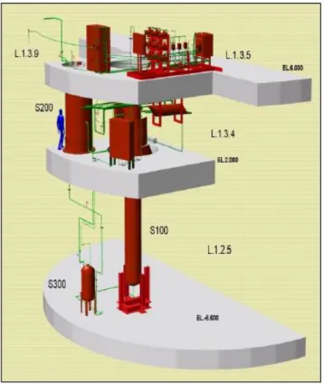
CIRCE consists of a cylindrical vessel (Main Vessel S100) filled with about 70 tons of molten Lead-Bismuth Eutectic (LBE) with argon cover gas and recirculation system, LBE heating and cooling systems, several test sections welded to and hung from bolted vessel heads for separate-effects and integral testing, and auxiliary equipment for eutectic circulation[1][2][3][4]. The facility is completed by a LBE storage tank (S200), a small LBE transfer tank (S300) and the data acquisition system (see Fig. 1). During the loading operations, the LBE is gradually transferred from the storage tank (S200) to the S300 vessel. Then, by pressurization of the S300 cover gas, the liquid metal gradually fills the test vessel (S100) from the bottom.
The main vessel S100 consists of a vertical vessel 8500 mm height, connected by gates to the other vessels. It is externally equipped with electrical heating cables, installed at the bottom and on the lateral surface. This heating system operates in a temperature range of 200-400°C.
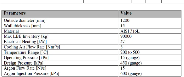
In order to guarantee the LBE top level and to prevent accidental overpressure, the main vessel is equipped with a skimming line and a passive pressure safety system. The S100 parameters are summarized in Tab. 1.
Fig. 1 – CIRCE isometric view.
Parameter Value
Outside Diameter 1200 mm
Wall Thickness 15 mm
Material AISI 316L
Max LBE Inventory 90000 kg
Electrical Heating 47 kW
Cooling Air Flow Rate 3 Nm3/s
Temperature Range 200-550°C
Operating Pressure 15 kPa (gauge)
Design Pressure 450 kPa (gauge)
Nominal Argon Flow Rate 15 Nl/s
Argon Injection Pressure 600 kPa (gauge)
Tab. 1 – CIRCE S100 main parameter.
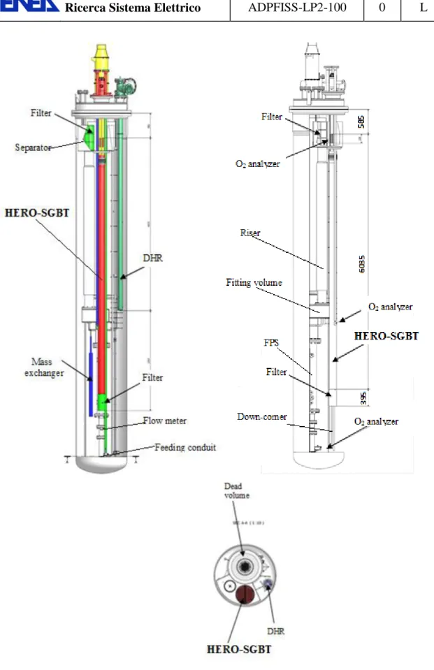
The Heavy liquid mEtal – pRessurized water cOoled tube (HERO) aims to study a 1:1 bayonet tube/s under conditions that represent, as much as possible, the operation of the ALFRED SG[5][6]. The facility is expected to be a suitable tool to support the validation process of TH-Sy codes and CFD codes coupled simulations. Schematic views of HERO test section, placed in the CIRCE main vessel (S100), is depicted in Fig. 2.
Down-comer: It is the volume between the test section and the main vessel, which allows the
hydrodynamic connection between the outlet section of the HERO-SGBT and the inlet section of the feeding conduit.
Feeding Conduit: it is the inlet pipe of the test section, which allows the hydrodynamic
development of the upward primary flow rate towards the flow meter.
Flow Meter: it is a Venturi-nozzle flow meter. Bubble tubes are adopted to measure the pressure
difference through the throat of the nozzle. The flow meter is directly connected to the HS, without a bypass, thus measuring the primary flow rate through the pin bundle.
Fuel Pin Simulator (FPS): it is a mechanical structure needed to take on the Heat Source (HS). It
is connected in the lower section to the flow meter and in the upper section to the insulation volume by means of the coupling flange. The coupling flange assures the sealing, avoiding the insulation volume flooding by LBE. In the upper section, the FPS is hydraulically linked to the fitting volume, ensuring continuity of the main flow path.
Fitting Volume: it is placed in the middle part of the test section, allowing the hydraulic
connection between the HS and the riser.
Riser: it is an insulated pipe (double wall pipe with air in the gap) connecting the fitting volume
with the separator. A nozzle is installed in the lower section to allow the argon injection inside this pipe[7][8].
Separator: it is a volume needed to connect the riser with the HERO-SGBT. It allows the
separation of the LBE flowing downward into the HX from the Argon flowing in the test section cover gas through the free surface. Moreover, the separator assures that the overall LBE flow rate flows directly into the HX (shell – side) before falling down in the down-comer. In addition, the separator works as an expansion vessel, allowing for fluid expansion during transient operations.
HERO-SGBT: it corresponds to the heat sink of the system. It consists in seven double-walls
bayonet tubes (with stainless steel powder filling the gap) with intermediate leakage monitoring fed by pressurized water (180 bar). It has a thermal duty of about 500 kW. It is an innovative heat exchanger mock-up (1:1) representative of a steam generator of a prototypical GEN IV lead cooled nuclear power the plant (ALFRED - Advanced Lead Fast Reactor European Demonstrator). Its main tasks are to characterize its thermal hydraulics performances and to provide a consistent database for code validation. For this purpose the HX is deeply instrumented allowing to obtain accurate measurements in order to investigate all the phenomena of interest in different operational conditions (head losses, conductive and convective flow regimes, thermo-hydraulic instability etc.). The SGBT main data are reported in Tab. 2 and Tab. 3.
Dead Volume: it is a component made of two concentric pipes. The inner pipe is connected, by
bolted junctions, to the FPS (by the coupling flange) and to the cover head. The volume inside the inner pipe is called Insulation Volume. The outer pipe is welded to the inner pipe in the lower end by a flange which allows a bolted connection between the dead volume and the fitting volume. It extends to the cover gas, above the free level. The annulus between the inner and outer pipes, kept melt-free by design, is linked to the cover gas and filled by a thermal insulator in order to reduce the radial heat flux towards the insulation volume.
Decay Heat Removal System: it corresponds to the heat sink of the system in the case of DHR
scenario, when the HX is unavailable. It is hydraulically de-coupled by the primary system being placed into the down-comer. The DHR heat exchanger has been designed to have a thermal duty of 40 kW.
exchanger based on PbO spheroids for the control of the oxygen content and in three oxygen sensor based on YSZ electrolyte cell installed in the CIRCE main vessel at three different positions for the on-line measurement of the oxygen content dissolved in the melt. Moreover an extractive oxygen gas analyser is installed for on-line monitoring of the oxygen content in the cover gas. Two filtering devices are installed in the coldest and hottest region of the pool respectively. One of the filtering sections, placed at the outlet section of the main Heat Exchanger is coupled with a suitable differential pressure transducer aiming to get information related to the plugging of the filtering section during the CIRCE operation
Secondary loop: the secondary loop is presently under commissioning and consists of an open
cycle. The feed-water line is fed by demineralized water at service pressure. Its main task is to provide sub-cooled water at 335°C, 180 bar to the HERO-HX by means of a pump and a pre-heating system. It consists of a pump, an electrically heated spiral pipe, a collector a by-pass line and a main seam line. The system is equipped with a main control valve to pressurize the test section at the start up and a bypass valve to perform an initial pre-heating.
Description Unit Steam line Helium line LBE side
Fluid -- Water - steam Helium LBE
Circulation mechanism -- Axial pump +
accumulator
Storage tank for leakage refilling
Gas enhanced
Main components -- 7 bayonet tubes,
steam chamber
Helium chamber SGBT unit shell
Bundle type and P/D - Triangular -- Shell
Operating inlet temperature °C 335 -- 480
Operating mass flow kg/s 0.330785 stagnant 44.573529
Design pressure bar 172 5.0 As CIRCE
Operating pressure bar 170 4.5 Hydraulic
head
Hydraulic head in design condition bar 0.7 -- --
Hydraulic head in test condition bar 0.7 -- --
Test pressure bar 180 -- --
Design temperature °C 432 432 As CIRCE
Volume m3 0.0083 0.0054 --
Empty weight kg 135 -- --
Code -- EN13445 -- --
Welding joint efficiency -- 1 -- --
Notified body -- TUV0948 -- --
Welding specification -- WKF/3479/1 -- --
Serial number -- 13173 -- --
CE - PED -- III Category B1+F Module --
Tab. 2 – HERO-CIRCE SGBT unit, main data.
Label Inner diameter [mm] Outer diameter [mm] Thickness [mm] Material
Feed-water slave tube 7.09 9.53 1.22 AISI-304
Feed-water tube gap 9.53 15.75 3.11 Slight vacuum
Feed-water outer tube 15.75 19.05 1.65 AISI-304
Annular riser gap 19.05 21.18 1.07 Water-steam
Second tube 21.18 25.40 2.11 AISI-304
Annular gap 25.40 26.64 0.62 AISI 316 powder
Third tube 26.64 33.40 3.38 AISI-304
2 Design and construction of the secondary loop
2.1 Description
The secondary loop is an open cycle loop fed by demineralized water. It pressurizes and preheats the water that fed the HERO SGBT unit and discharge the superheated steam that leaves the HERO-SGBT to the environment.
The conceptual scheme is depicted in Fig. 3. It is constituted by these main components:
The demineralizer (already installed in the experimental hall)
The pumping system
The preheating system
The collector
The main pipeline (PIPE-50, PIPE-100, PIPE-200 and PIPE-300)
The bypass pipeline (PIPE-400)
Valves to pressurize and operate the facility
The discharge. Start-up:
Valves V-200-01 and V-300-01 are closed valve V-200-01 is opened: un-pressurized water (at environmental temperature, 10-20% of the nominal rate), flows into the circuit and is discharged.
The spiral pre-heater is activated and the facility runs in this status up to the achievement of steam at its outlet (>100°C, >1 bar).
When only steam flows in the circuit, 200-01 and 300-01 are gradually opened and V-400-01 is closed. CIRCE pool conditions are set from the beginning to avoid thermal stresses in the tubes once the steam enters the SGBTs.
From this point, pressurization and feed-water heat-up start by gradually closing valve V-300-01 and adapting the power to the spiral preheater and to the CIRCE FPS.
The start-up ends with the feed-water inlet at 335°C, 172 bar and nominal flow rates (water and LBE in CIRCE).
Fig. 3 – CIRCE HERO secondary loop scheme.
2.2 Pre-heater, collector and pump
The construction/acquisition of the spiral pre-heater, the collector and the pump were assigned to LIMAIOX. These components will be delivered together at Brasimone.
2.2.1 Spiral pre-heater
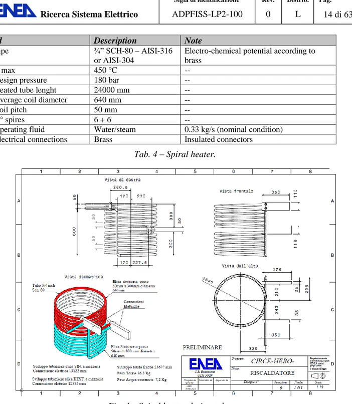
The spiral pre-heater supplies the power to the feed-water in order to achieve adequate conditions to enter the HERO-SGBT units (from 15°C up to 335°C, 172 bar). Since the required power is in the order of 500 kW, it is necessary to adopt a system to preheat the feed-water which was finally decided to be based on electrical heating of the feed-water tube. RELAP-5 calculations were performed and the heating tube length was estimated to be 24 m (considering a ¾” SCH-80 – AISI-316 tube). In order to make it compact, spiral geometry has been selected. The construction of the spiral heater was assigned according to these requirements.
Design data given in
Pump V-50-01 Spiral heater 150 Collector 250 PIPE-200 PIPE-300 Demineralizer PIPE-100 PIPE-400 Discharge V-300-01 HERO-SGBT V-200-01 V-400-01 PIPE-50
;
Designed and constructed according to Fig. 4;
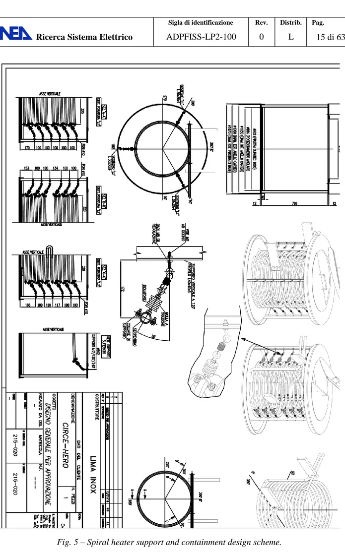
To be thermally insulated by means of a cylindrical containment whose design was in charge to the supplier that should be able to guarantee an HTC less than di 5.5 W/(m2 K);
To be anchored with an opportune system whose design was in charge to the supplier that should be electrically insulated.
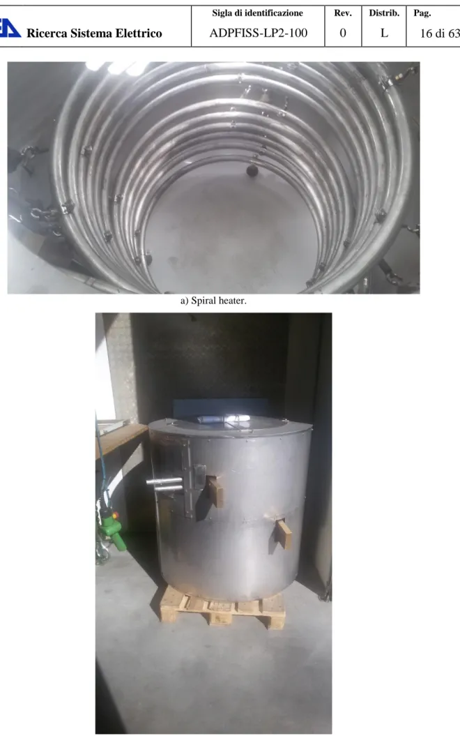
LIMAINOX provided the constructive design reported in Fig. 5. The components have been constructed and are going to be delivered to ENEA CR Brasimone, Fig. 6.
Id Description Note
Pipe ¾” SCH-80 – AISI-316
or AISI-304
Electro-chemical potential according to brass
T max 450 °C --
Design pressure 180 bar --
Heated tube lenght 24000 mm --
Average coil diameter 640 mm --
Coil pitch 50 mm --
N° spires 6 + 6 --
Operating fluid Water/steam 0.33 kg/s (nominal condition) Electrical connections Brass Insulated connectors
Tab. 4 – Spiral heater.
a) Spiral heater.
b) Spiral heater containment.
2.2.2 Collector
The collector should distribute the feed-water to seven bayonet tubes. The design and construction of this component has been assigned to LIMAINOX according to these requirements.
The component should be designed in order to achieve as uniform as possible distribution of the feed-water to the seven bayonet tubes (this is expected to impact the component length, the distribution of the outlet nozzles and the introduction of dedicated grids).
The working fluid in nominal conditions is water at 335°C, 170 bar, 0.33 kg/s..
The material is AISI-316 or AISI-304.
The component has been designed (Fig. 7) and constructed. It is going to be delivered to ENEA CR Brasimone.
Fig. 7 – Collector design.
2.2.3 Pump
The pump has in charge to pressurize the feed-water from the service pressure up to 172 bar. Since it is required to operate at constant pressure and constant mass flow rate (into a range +10/-50 of the nominal flow rate), a piston pump with electric motor plus an accumulator to reduce its oscillations has been selected.
The pump should fulfill the following requirements:
Motor – pump group with adequate number of rpm (es. 1400 rpm) including its regulating pressure valve and manometer, without electrical box.
Design data accordino to Tab. 5.
Accumulator mounted at the pump outlet. It should be able to reduce oscillations down to 1% both at Pn and 0.5 Pn.
The pump triplex RW 5530 has been identified among those reported in Tab. 6. The accumulator was designed as reported in Fig. 8.
Id Description Note
Max pressure 200 bar --
Operating pressure 180 bar --
Nominal flow rate, Pn 19.85 l/min -- Flow rate range +10%Pn, -50%Pn --
Operating temperature 20°C --
Type Motor-pump piston --
Accumulator yes It should reduce oscillations below 1% Pn
Tab. 5 – Pump requirements.
Fig. 8 – Influence of the accumulator.
2.3 Control and operational valves
The control valves have been supplied by SAMSON according the following requirements:
Operating pressure [1-172 bar]
Operating temperature [20-450°C]
Fluid: water, water/steam mixture, superheated steam
One valve (V-300-01) 3” with possibility to regulate 0.3-1.1 of nominal flow rate (which is 0.33 kg/s)
Two valves (V-200-01 and V-400-01) 1”.
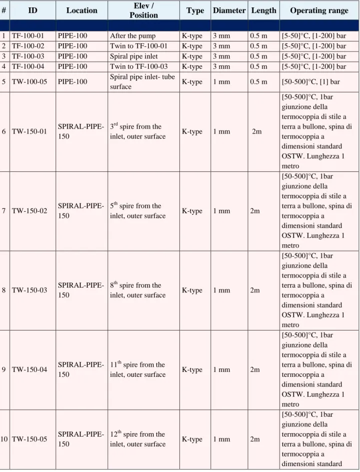
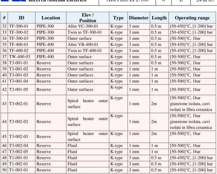
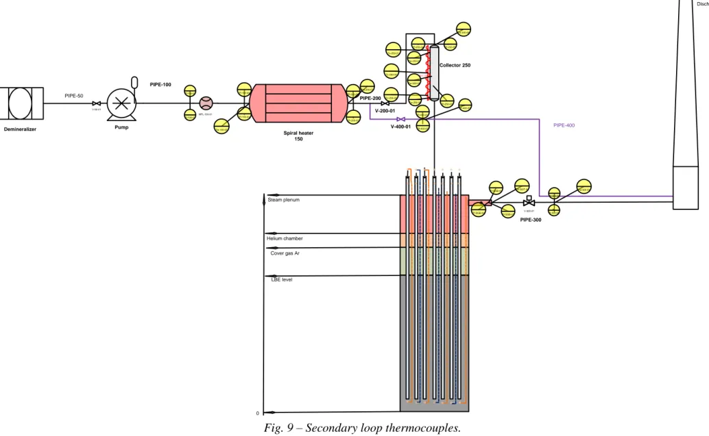
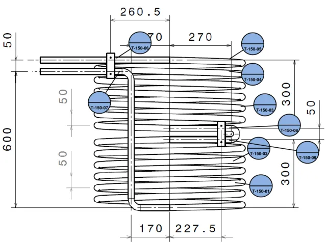
2.4 Thermocouples instrumentation
The secondary loop has been mapped with 37 thermocouples whose description is given in Tab. 9,
Fig. 9 and Fig. 10.
# ID Location Elev /
Position Type Diameter Length Operating range
1 TF-100-01 PIPE-100 After the pump K-type 3 mm 0.5 m [5-50]°C, [1-200] bar
2 TF-100-02 PIPE-100 Twin to TF-100-01 K-type 3 mm 0.5 m [5-50]°C, [1-200] bar
3 TF-100-03 PIPE-100 Spiral pipe inlet K-type 3 mm 0.5 m [5-50]°C, [1-200] bar
4 TF-100-04 PIPE-100 Twin to TF-100-03 K-type 3 mm 0.5 m [5-50]°C, [1-200] bar
5 TW-100-05 PIPE-100 Spiral pipe inlet- tube
surface K-type 1 mm 0.5 m [50-500]°C, [1] bar
6 TW-150-01
SPIRAL-PIPE-150
3rd spire from the
inlet, outer surface K-type 1 mm 2m
[50-500]°C, 1bar giunzione della termocoppia di stile a terra a bullone, spina di termocoppia a dimensioni standard OSTW. Lunghezza 1 metro 7 TW-150-02 SPIRAL-PIPE-150
5th spire from the
inlet, outer surface K-type 1 mm 2m
[50-500]°C, 1bar giunzione della termocoppia di stile a terra a bullone, spina di termocoppia a dimensioni standard OSTW. Lunghezza 1 metro 8 TW-150-03 SPIRAL-PIPE-150
8th spire from the
inlet, outer surface K-type 1 mm 2m
[50-500]°C, 1bar giunzione della termocoppia di stile a terra a bullone, spina di termocoppia a dimensioni standard OSTW. Lunghezza 1 metro 9 TW-150-04 SPIRAL-PIPE-150
11th spire from the
inlet, outer surface K-type 1 mm 2m
[50-500]°C, 1bar giunzione della termocoppia di stile a terra a bullone, spina di termocoppia a dimensioni standard OSTW. Lunghezza 1 metro 10 TW-150-05 SPIRAL-PIPE-150
12th spire from the
inlet, outer surface K-type 1 mm 2m
[50-500]°C, 1bar giunzione della termocoppia di stile a terra a bullone, spina di termocoppia a
# ID Location Elev /
Position Type Diameter Length Operating range
OSTW. Lunghezza 1 metro
11 TW-150-06
SPIRAL-PIPE-150 Electric joints K-type 1 mm 2m
[50-500]°C, 1bar giunzione della termocoppia di stile a terra a bullone, spina di termocoppia a
dimensioni standard OSTW. Lunghezza 1 metro
12 TW-150-07
SPIRAL-PIPE-150 Electric joints K-type 1 mm 2m
[50-500]°C, 1bar giunzione della termocoppia di stile a terra a bullone, spina di termocoppia a
dimensioni standard OSTW. Lunghezza 1 metro
13 TW-150-08
SPIRAL-PIPE-150 Electric joints K-type 1 mm 2m
[50-500]°C, 1bar giunzione isolata, cavi isolati in fibra ceramica
14 TW-150-09
SPIRAL-PIPE-150 Electric joints K-type 1 mm 2m
[50-500]°C, 1bar giunzione della termocoppia di stile a terra a bullone, spina di termocoppia a
dimensioni standard OSTW. Lunghezza 1 metro
15 TF-200-01 PIPE-200 Spiral pipe outlet K-type 3 mm 0.5 m [50-450]°C, [1-200] bar
16 TF-200-02 PIPE-200 Twin to TF-200-01 K-type 3 mm 0.5 m [50-450]°C, [1-200] bar
17 TW-200-03 PIPE-200 Spiral pipe outlet,
outer surface K-type 1 mm 0.5 m [50-500]°C, 1bar
18 TF-200-04 PIPE-200 Collector inlet K-type 3 mm 0.5 m [50-450]°C, [1-200] bar
19 TF-200-05 PIPE-200 Twin to TF-200-04 K-type 3 mm 0.5 m [50-450]°C, [1-200] bar
20 TW-200-06 PIPE-200 Collector inlet, outer
surface K-type 1 mm 0.5 m [50-500]°C, 1bar
21 TW-250-01 Collector-250 Outer surface top K-type 1 mm 1 m [50-500]°C, [1] bar
22 TC-250-02 Collector-250 Heating cable top K-type 1 mm 1 m [50-500]°C, [1] bar
23 TW-250-03 Collector-250 Outer surface middle K-type 1 mm 1 m [50-500]°C, [1] bar 24 TC-250-04 Collector-250 Heating cable middle K-type 1 mm 1 m [50-500]°C, [1] bar 25 TW-250-05 Collector-250 Outer surface bottom K-type 1 mm 1 m [50-500]°C, [1] bar 26 TC-250-06 Collector-250 Heating cable bottom K-type 1 mm 1 m [50-500]°C, [1] bar
27 TF-250-07 Collector-250 After the last grid K-type 3 mm 1 m [50-450]°C, [1-200] bar
28 TF-SGT-01 HERO-SGBT Steam plenum outlet
nozzle K-type 1 mm 1 m [50-450]°C, [1-200] bar
29 TF-SGT-02 HERO-SGBT 120° to TF-SGT-01 K-type 1 mm 1 m [50-450]°C, [1-200] bar
30 TF-SGT-03 HERO-SGBT 240° to TF-SGT-01 K-type 1 mm 1 m [50-450]°C, [1-200] bar
# ID Location Elev /
Position Type Diameter Length Operating range
32 TF-300-01 PIPE-300 After VC-300-01 K-type 3 mm 0.5 m [50-450]°C, [1-200] bar
33 TF-300-02 PIPE-300 Twin to TF-300-01 K-type 3 mm 0.5 m [50-450]°C, [1-200] bar
34 TF-300-03 PIPE-300 Outer surface K-type 1 mm 0.5 m [50-500]°C, 1bar
35 TF-400-01 PIPE-400 After VB-400-01 K-type 3 mm 0.5 m [50-450]°C, [1-200] bar
36 TF-400-02 PIPE-400 Twin to TF-400-01 K-type 3 mm 0.5 m [50-450]°C, [1-200] bar
37 TW-400-03 PIPE-400 Outer surface K-type 1 mm 0.5 m [50-500]°C, 1bar
38 T3-001-01 Reserve Outer surfaces K-type 1 mm 0.5 m [50-500]°C, 1bar
39 T3-001-02 Reserve Outer surfaces K-type 1 mm 1 m [50-500]°C, 1bar
40 T3-001-03 Reserve Outer surfaces K-type 1 mm 1 m [50-500]°C, 1bar
41 T3-001-04 Reserve Outer surfaces K-type 1 mm 1 m [50-500]°C, 1bar
42 T3-001-05 Reserve Outer surfaces K-type 1 mm 1 m [50-500]°C, 1bar
43 T3-002-01 Reserve Spiral heater outer
surface
K-type
1 mm 2m
[50-500]°C, 1bar giunzione isolata, cavi isolati in fibra ceramica
44 T3-002-02 Reserve Spiral heater outer
surface
K-type
1 mm 2m
[50-500]°C, 1bar giunzione isolata, cavi isolati in fibra ceramica
45 T3-002-03 Reserve Spiral heater outer
surface
K-type 1 mm 2m [50-500]°C, 1bar
46 T3-002-04 Reserve Fluid K-type 1 mm 1 m [50-500]°C, 1bar
47 T3-002-05 Reserve Fluid K-type 1 mm 1 m [50-500]°C, 1bar
48 T1-001-01 Reserve Fluid K-type 3 mm 0.5 m [50-450]°C, [1-200] bar
49 T1-002-01 Reserve Fluid K-type 3 mm 0.5 m [50-450]°C, [1-200] bar
50 T1-003-01 Reserve Fluid K-type 3 mm 0.5 m [50-450]°C, [1-200] bar
Pump V-50-01 Spiral heater 150 MFL-100-01 V-200-01 Collector 250 H-C-250 Tf-100-02 Tf-100-01 Tf-100-03 Tf-100-04 PIPE-200 Tf-200-05 Tf-200-04 Tc-250-01 Tw-250-02 Tf-250-07 PIPE-300 Demineralizer PIPE-100 PIPE-400 V-400-01 Tf-400-01 Tf-400-02 Tf-SGB-03 Tf-SGB-02 Tf-SGB-01 Discharge V-300-01 Tf-200-01 Tf-200-02 Tc-250-03 Tw-250-04 Tc-250-05 Tw-250-06 PIPE-50 Tf-300-02 Tf-300-01 LBE level Cover gas Ar Helium chamber Steam plenum 0 Tw-100-05 Tw-200-03 Tw-200-06 Tf-400-03 Tw-300-03 TW-SGT-04
T-150-01 T-150-02 T-150-03 T-150-04 T-150-05 T-150-06 T-150-07 T-150-08 T-150-09
REFERENCES
[1] P. Turroni, L. Cinotti, G. Corsini, L. Mansani, “The CIRCE Facility”,
AccApp’01&ADTTA’01, Nuclear Application in the new Millennium, Reno (Nevada- USA), November 11-15, 2001.
[2] G. Benamati, G. Bertacci, N. Elmi, G. Scaddozzo, “Report on Gas Enhanced Circulation Experiments and Final Analysis (TECLA D41)”, Report ENEA HS-A-R-016, 2005.
[3] G. Bandini, I. Di Piazza, P. Gaggini, A. Del Nevo, M. Tarantino, “CIRCE experimental set-up design and test matrix definition”, ENEA UTIS-TIC Technical Report, IT-F-S-001, 28/02/2011.
[4] M. Tarantino, G. Scaddozzo, “Test specifications of the Integral Circulation Experiments”, Report ENEA ET-F-S-001, Deliverable D. 4.15, DM4 DEMETRA, IP-EUROTRANS, 2006.
[5] D. Rozzia, A. Del Nevo, M. Tarantino, P. Gaggini, D. Vitale Di Maio, G. Caruso, L. Gramiccia, “Fornitura Scambiatore di Calore a Tubi a Baionetta” ADPFISS-LP2_028. (It).
[6] D. Rozzia, “Experimental and computational analyses in support to the design of a SG
mock-up prototype for LFR technology applications”, PhD master Thesis, October 2014. [7] W. Ambrosini, M. Azzati, G. Benamati, G. Bertacci, L. Cinotti, N. Forgione, F. Oriolo, G.
Scadozzo, M. Tarantino, "Testing and qualification of CIRCE instrumentation based on bubble tubes", Journal of Nuclear Materials, pp. 293-298, 2004.
[8] G. Benamati, C. Foletti, N. Forgione, F. Oriolo, G. Scaddozzo, M. Tarantino, “Experimental study on gas-injection enhanced circulation performed with the CIRCE facility”, Nuclear Engineering and Design, vol. 237, pp. 768-777, Iss. 7, 2007.
PART-II: HERO-CIRCE engineering handbook
List of figures and tables
Figure 1 – CIRCE isometric view... 30 Figure 2 – Arrangement and geometry of the seven tubes and the hexagonal box. ... 31 Figure 3 – HERO – CIRCE SGBT unit. ... 33 Figure 4 – CIRCE primary flow path. ... 34 Figure 5 – CIRCE – HERO test section. ... 35 Figure 6 – FPS cross section. ... 36 Figure 7 – FPS mechanical drawing. ... 37 Figure 8 – Spacer grid. ... 38 Figure 9 – Cylindrical wrapper... 39 Figure 10 – Fuel Pin Simulator overview. ... 39 Figure 11 – TCs arrangement at the inlet and outlet section of the FPS. ... 40 Figure 12 – Release pipe overview. ... 40 Figure 13 – Release pipe. ... 41 Figure 14 – Fitting volume. ... 42 Figure 15 – Argon injector. ... 42 Figure 16 – Fitting volume: zones. ... 43 Figure 17 – Fitting volume: zones and volumes. ... 43 Figure 18 – Riser overview. ... 44 Figure 19 – Filter. ... 45 Figure 20 – HERO inlet. ... 45 Figure 21 – Separator overview. ... 46 Figure 22 – CIRCE upper head. ... 47 Figure 23 – HERO – CIRCE SGBT unit: main overview ... 47 Figure 24 – HERO – CIRCE unit: bundle arrangement. ... 48 Figure 25 – Section of a bayonet tube bottom end. ... 49 Figure 26 – HERO – CIRCE unit: spacer grid. ... 50 Figure 27 – HERO – CIRCE unit: end of bayonet tubes. ... 51 Figure 28 – SG filter. ... 51 Figure 29 – LBE free surface. ... 52 Figure 30 – Nodalization scheme of primary circuit... 63
Table 1 – CIRCE S100 main parameters. ... 31 Table 2 – Fitting volume. ... 42 Table 3 – SGBT main dimensions... 49
Table 4 – Zircofoam 250 thermal conductivity. ... 50 Table 5 – HERO – CIRCE unit: instrumentation. ... 55 Table 6 – HERO – CIRCE facility: geometrical parameters. ... 61 Table 7 – Energy loss coefficients. ... 62
1 Introduction
The experimental test section HERO (Heavy liquid mEtal pRessurized water cOoled tube) will be installed into the CIRCE (CIRColazione Eutettico) experimental facility. The main purpose of the HERO test section is to study the behavior of the bayonet tubes of the ALFRED steam generator, in scale 1:1 and as much as possible at the ALFRED operating conditions.
The present document is aimed at providing a detailed description of the whole facility giving all the input parameters required for modeling and simulating the system through computer programs.
1.1 CIRCE conceptual design
The CIRCE facility is an experimental test section dedicated to the study of innovative nuclear systems cooled by liquid heavy metal. It consists of a main vessel (S100), inside which is installed the HERO test section, and two auxiliary tanks S200 and S300.
The vessel is filled with about 70 tons of a lead-bismuth eutectic alloy (LBE) and above the free level an argon cover is present. The S200 auxiliary tank is used for the liquid metal storage during maintenance phases. During the charging phase of the vessel, the LBE passes from the S200 storage tank to the intermediate S300 tank. Through the S300 tank, the LBE is subsequently introduced from the bottom, into the S100 vessel.
The facility is shown in the Figure 1 while the main parameters are reported in Table 1.
Table 1 – CIRCE S100 main parameters.
1.2 HERO conceptual design
The HERO test section is composed by a hexagonal shell in which 7 bayonet tubes (SGBT Steam Generator Bayonet Tube) are included. The bayonet tubes have the same geometrical configuration, included the dimensions (1:1 scale), of those foreseen in the ALFRED steam generators.
The HERO test section is installed into the CIRCE main vessel. The LBE enters the HERO test section from the upper part, flows into the subchannels (6 meters long) and exits at the bottom of the heat exchanger reaching again the CIRCE pool.
A simplified scheme of the bayonet tubes layout is shown in Figure 2.
2 CIRCE and HERO Overview
The present chapter is aimed at providing a brief overview of the CIRCE primary loop with the HERO test section installed into it.
In the next chapter, a more detailed description of each component, included the main geometrical parameters, position and type of the instrumentation and all the information required for the system nodalization, are reported.
2.1 Primary loop
The primary loop is characterized by: the LBE pool;
the riser;
the fuel pin simulator (FPS); the steam generator (HERO); the DHR (Decay Heat Removal).
All the primary circuit components are submerged in the LBE pool; above the LBE free level there is the argon cover gas. Starting from the pool, the liquid metal is pushed into the feeding conduit, where a Venturi-nozzle flow meter is installed. The LBE, flowing upward, increase its temperature passing through the FPS, which is characterized by 37 electrically heated pins with a maximum thermal power of about 25 kW each.
After flowing into the FPS, the LBE reaches a fitting volume and hence the riser that bring the LBE at the separator, placed in the upper region of the main vessel. Into the fitting volume there is a nozzle that injects argon at the riser bottom section in order to enhance the upward circulation of the LBE coolant (gas-injection enhanced circulation). At the top of the riser, the separator allows the separation of the LBE and the argon previously injected; the argon gas comes back into the cover gas.
From the top of the main vessel, the LBE enters the HERO test section passing through the bayonet tube sub-channels. Once the LBE is cooled, it exits from the heat exchanger reaching the CIRCE main pool.
Figure 5 – CIRCE – HERO test section.
In Figure 4 there is dead volume that performs two main functions: the first one is to guarantee the placement of the FPS and the location of power and instrumentation cables; the second one is to limit the volume that has to be filled with the LBE.
3 Primary System
This chapter provides a detailed descriptions of the components belonging to the test facility primary loop. For each component, all geometrical parameters, instrumentation location and typology and all information needed for the plant nodalization are reported.
The whole system consists of: feeding conduit, fuel pins simulator, fitting volume, riser, separator, heat exchanger and pool.
At the end of the present chapter a table with the main geometrical parameters is reported.
3.1 Feeding Conduit
The feeding conduit is composed by three parts; two of these (the bottom and the upper ones) are 4 "sch. 40 tubes with a respectively length of 300 and 270 mm. Between these two parts is foreseen a Venturi flow meter (Venturi - Nozzle), 300 mm long. The three components are connected each other by 4" flanges.
Concerning the flow meter performance, it has been shown, through experimental activity previously carried out on the CIRCE facility, that a pressure drop of about 9 kPa is expected for the nominal LBE flow.
The flow measurement is performed through two pressure measurement lines. A further pressure line is foreseen in the upper tube of the feeding conduit.
3.2 Fuel Pin Simulator (FPS)
Once the LBE passes through the feeding conduit, it reaches the system heat source: named Fuel Pin Simulator (FPS).
The FPS is characterized by 37 electrically heated pins and by a rated power of about 800 kW. The design of the FPS is aimed at providing, with the LBE having an average speed of 1 m/s, a coolant temperature gradient of 100 °C/m and a pin power density of 500 W/cm3.
The electrically heated pins are characterized by a hexagonal lattice with a pitch to diameter ratio equal to 1.8.
Each pin is characterized by an outer diameter equal to 8.2 mm, a maximum thermal power of about 25kW and by a heat flux, at the pin wall, of 1 MW/m2. The FPS pins length is 1885 mm; the heat source is limited to the central 1000 mm. The other 885 mm constitute the upstream and downstream mixing zones, placed immediately below and over the heating region. These two mixing zones are respectively characterized by a length of 300 and 485 mm.
The pins are kept in their correct position, along their height, by means of three spacer grids (for the locations see Figure 7). Moreover, a lower grid, which guarantees the LBE inlet, and an upper grid, which acts as FPS cap, are placed at the bottom and upper pins edges.
Figure 8 – Spacer grid.
The three spacer grids are located as follow:
The first and the third ones are located at heights corresponding to the interfaces of the heating region and the mixing zones.
The second spacer grid is located at the center of the heating zone.
The FPS geometrical parameters, reported in the Table 6, are evaluated taking into account the actual position of each grid. The pressure drop coefficients corresponding to the grids have been evaluated through the Rehme correlation.
The FPS hexagonal wrapper is included in a cylindrical shroud, where holes for the instrumentation connections are obtained. The gap, between the inner hexagonal wrapper and the outer cylindrical shroud, is filled with stagnant LBE.
Figure 9 – Cylindrical wrapper.
The FPS instrumentation is characterized by:
three TCs at the active zone inlet: placed, at 120°, at 20 mm above the first spacer grid;
three TCs at the active zone outlet: placed, at 120°, at 20 mm below the third spacer grid;
pressure outlet line at 223 mm from the FPS inlet;
pressure outlet line at 463 mm from the FPS inlet (240 mm above the previous one).
Figure 11 – TCs arrangement at the inlet and outlet section of the FPS.
3.3 Release Pipe
The release pipe is a 8" sch. 40 pipe (see Figure 12 and Figure 13). It is included inside the fitting volume with which it is in communication by means of four holes. Each hole is characterized by a flow area of 238.54 cm2.
Figure 13 – Release pipe.
In the bottom region there are two openings to guarantee the LBE flow. The release pipe can be internally subdivided into two regions:
the first 115 mm long,
the second 645 mm long.
The first region has a flow area equal to the annular zone included between the inner wall of the release pipe and the FPS outer wall (the FPS enters into the release pipe). This flow area is evaluated to be 229.985 cm2.
The second region has a flow area equal to the difference between the release pipe inner section and the zone occupied by the electrically heated pins of the FPS. The upper part of the electrically heated pins exit from the FPS through the upper grid and they reach the dead volume up to the connection flange. The flow area of the second region was evaluated to be equal to 304.115 cm2. Three thermocouples are placed in the openings that connect the release pipe to the fitting volume.
3.4 Fitting Volume
The main task of the fitting volume (see Figure 14) is to connect the release pipe to the riser. Once the LBE, exiting from the release pipe, reaches the fitting volume, it is driven to the riser inlet.
Figure 14 – Fitting volume.
8 1 Cylinder th.8 d600 L525 [mm] AISI304
7 1 Flange SO RF150 10” AISI304
6 1 Pipe 10” Sch.40 AISI304
5 1 Sheet th.15 [mm] AISI304
4 Flange riser support d340 th.20 [mm] AISI304
3 1 Sheet th.15 [mm] AISI304
2 1 Flange d700 th.30 [mm] AISI304
1 1 Folded sheet th.8 [mm] AISI304
POS. Q.TY DESCRIPTION MATERIAL
Table 2 – Fitting volume.
The fitting volume can be divided into the two following zones (see Figure 16):
the first, at the bottom, where the LBE is driven towards the coupling flange with the riser (see position 4 in Figure 14);
the second is the cylindrical upper region where the LBE is stagnant.
The flow area of the first region has been evaluated subtracting areas of the release pipe and of the gas injection nozzle to the fitting volume section. This is represented in the Figure 15.
The first zone is characterized by the flow area equal to 0.3214 m2 and the length equal to 290 mm. The second zone is almost entirely occupied by the dead volume structure, which penetrates into the fitting volume (see Figure 17). In particular, dividing the area into two volumes, the following geometrical parameters can be obtained:
volume 1: length of 142.5 mm and flow area of 0.0549 m2;
volume 2: length of 142.5 mm and flow area of 0.1854 m2. At half height of the first zone is placed a pressure outlet line.
Figure 16 – Fitting volume: zones.
Figure 17 – Fitting volume: zones and volumes.
3.5 Riser
The riser is a double-wall pipe characterized by an overall length of 3.81 m. It allows the LBE to flow upward, thanks to the gas-injection enhanced circulation, from the fitting volume to the separator.
In order to reduce the hot fluid heat loss towards the main pool, a double-wall pipe has been selected for the riser. The inner tube has an inner diameter of 203 mm and it is included, for a length of 3020 mm, into a larger tube, as shown in Figure 18.
The gap between the two pipes is filled with air in order to reduce the heat loss. The riser is equipped by an axial bellow with a maximum length of 310 mm. The upper edge of the riser, which reaches the separator penetrating it of 102 mm, is coupled with a filter.
The pressure drop due to the filter can be taken into account through a K coefficient equal to 7. Moreover, the riser is equipped with two pressure gauges located at the inlet and at the outlet of the inner tube.
Figure 19 – Filter.
3.6 Separator
The separator, made by metal sheets, creates a volume dedicated to the separation of the hot LBE and the argon gas. The separation occurs since the hot LBE is driven downward, towards the heat exchanger inlet, while the argon can flow upward reaching the cover gas upper volume.
At the same time the separator guarantees the connection between the riser and the HERO-SGBT test section. The flow path connection is obtained through 6 openings present on the heat exchanger shroud; each of them is characterized by a flow area of 84.566 cm2.
The separator walls force the LBE to flow through the heat exchanger sub channels for reaching the down comer. In order to avoid that LBE would overcome the separator, the separator walls have a height of 0.608 m.
Moreover, the separator has the function of an expansion tank, allowing the LBE to change its volume during transients.
Because of many pipes and components are into the separator volume, the flow area has been evaluated splitting the separator volume into two different zones along the vertical.
The first zone includes the riser, which penetrates into the separator, and from the steam generator hexagon wrapper. It corresponds to a flow area of 0.2338 m2 for a height of 102 mm. The upper edge of the riser is included in this zone. The second zone is affected by the presence of the hexagonal HERO wrapper and it is characterized by a flow area of 0.2715 m2 and height of 498 mm.
In the first zone two holes are foreseen for pressure lines and thermocouples installation.
Figure 21 – Separator overview.
3.7 Pool
The CIRCE pool is characterized by the vessel inner volume, specifically volumes that are not occupied by circuit and/or auxiliary components.
For simplicity, the pool has been subdivided in 14 zones; each of them presents specific geometrical parameters, which depend on equipment placed within the S100.
The first three volumes are the upper ones; they are placed above the separator walls. The volume of these three zones are only partially filled with LBE. The rest of the space is occupied by the argon gas, which constitutes the cover gas volume. Of these three volumes, the first and second include the zone from the separator walls up to the connection flange with the S100 upper head. They respectively have lengths of 70 and 230 mm and flow areas of 0.7252 and 0.987 m2. The third
volume is the space inside the upper head and it is showed in Figure 22. The geometric parameters of the third volume are: length of 210 mm and flow area of 0.95926 m2. The other seven volumes include the down comer and the lower plenum. Each of them is characterized by specific dimensions that are summarized in the Table 6.
Aimed at measuring thermal stratification during transients within the S100 pool, a total of 115 thermocouples are installed into it.
Figure 22 – CIRCE upper head.
3.8 HERO SGBT
The HERO test section assembly is shown in Figure 23.
In the Figure 24 the CIRCE-HERO bundle is shown; for further details concerning the geometrical arrangement are see Figure 2.
Figure 24 – HERO – CIRCE unit: bundle arrangement.
The assembly is characterized by a 14” flange with a thickness of 30 mm (see position 1 in the Figure 23), which connects the test section to the CIRCE experimental facility. On the flange 7 holes for the bayonet tubes and 1 for the instrumentation are obtained. The flange has also to support the Helium chamber, the steam chamber, the bayonet tubes and hexagonal wrapper.
The Helium chamber is slightly pressurized in order to increase the heat transfer from the primary LBE to the steam flowing inside the bayonet tubes and, at the same time, to make easier the
detection of possible leakage. The helium chamber, which is made of a 6" sch. 40 pipe, is welded at its bottom edge to the flange while the upper edge is welded to a septum that guarantees the separation of helium chamber and steam chamber. On both the flange and the septum, the 7 holes for passing the bayonet tubes are obtained.
The steam chamber, which has to collect the superheated steam (170 bar and 430°C) coming from the steam generator, is made by a 6" sch.120 pipe. At the top of the steam chamber, there is a plate that seals the HERO test section; on this plate the bayonet tube upper edges are fixed. The superheated steam is extracted from the chamber through a 2 ½" sch.80 outlet nozzle.
Both chambers are equipped with 1" sch.40 radial nozzles to connect cables to the internal instrumentation (i.e. thermocouples installed on the bayonet tubes).
The feed water reaches the 7 bayonet tubes through Swagelok connections that pass through the test section upper plate and through a changeable orifice plate. The bayonet tubes consist of four concentric tubes, as shown in Figure 25. In particular Figure 25 shows a detail of the bottom region of a bayonet tube (see also Figure 27).
Figure 25 – Section of a bayonet tube bottom end.
21 1 Third tube: OD 33.4 th.3.38 [mm]
16 1 Plate: OD 25.4 th.9 [mm]
7 1 Slave tube: OD 9.53 th.1.22 [mm]
6 1 Inner tube: OD 19.05 th.1.65 [mm]
4 1 Second tube: OD 25.4 th.2.11 [mm]
POS. Q.TY DESCRIPTION
The slave and the inner tubes pass through the steam chamber while the helium chamber is crossed by the slave, the inner and the second tubes. Hence the bayonet tubes enter the main vessel S100 through the connection flange, at which the third tube is connected through a bellows. Inside the slave tube the feed water (cold) flows downward; during the descendent path, the water is preheated.
Once the bottom edge of the slave tube is reached, the water changes its direction of 180° flowing upward between the outer wall of the inner tube and the inner wall of the second tube. In this zone the water vaporizes reaching the superheated state before entering the steam chamber. The primary coolant, the LBE, flows downward in contact with the outer wall of the third.
Two gaps are present in each bayonet tube:
between the slave and the inner tubes;
between the second and the third tubes.
The first gap (i.e. between the slave and inner tubes) is filled with a thermal insulator, the ZIRCOFOAM 250, in order to minimize the heat transfer between the cold feed water and the hot superheated steam; it allows to increase the thermodynamic efficiency of the steam generator. The thermal conductivity of the ZIRCOFOAM 250 as a function of the temperature is shown in Table 4. The second gap (i.e. between the second and third tubes) is filled with SiC powder and slightly pressurized helium. These materials have been selected to guarantee good heat transfer performance (i.e. SiC thermal conductivity) and at the same time to possibility of detecting any leakage (i.e. connection with the helium chamber). The mutual position of the four tubes that constitute the bayonet tube is guaranteed by spacer grids (see Figure 26); they also have to maintain the correct thermocouples position in the operating conditions.
Temperature [K] Thermal Conductivity [ W / m K ]
423.15 0.060
523.15 0.071
673.15 0.088
873.15 0.113
Table 4 – Zircofoam 250 thermal conductivity.
At the bayonet tube bottom edge, on the lower plate (see position 16 in Figure 25), a 1/8” NPT penetration is foreseen to allow the connection of a pressure gauge transducer; if not needed it can be sealed with a swagelok cap. In Figure 27 a view of the bayonet tube bottom end is shown.
Figure 27 – HERO – CIRCE unit: end of bayonet tubes.
The 7 bayonet tubes are located into a hexagonal wrapper, which is thermally insulated from the CIRCE pool through a tube placed, concentric, around the wrapper. The gap between the hexagonal wrapper and the cylindrical shroud is filled with air. The final section of the steam generator is coupled with a mechanical filter; a representation of the mechanical filter is shown in Figure 28. For the test section modelization, the filter has been considered through a K coefficient equal to 7.
Figure 28 – SG filter.
On the connection flange there are three 2” nozzles, each equipped with a connection flange. These nozzles are needed for installing the oxygen probes.
The test section is characterized by the following instrumentation:
75 thermocouples;
2 absolute pressure transducers placed at the inlet and at the outlet of the test section;
8 flow meters, 1 placed upstream of the test section to measure the overall mass flow, the others placed at the inlet of each bayonet tube.
A complete list of the test section instrumentation is reported in Table 5.
3.9 Geometrical data summary
The test section geometrical data, required for the nodalization of the overall experimental facilty, are reported in Table 6. All the elevations reported in the table are referred to the LBE free level, assumed to be equal to 0, as reported in the CAD drawings; this is also represented in the Figure 29.
Figure 29 – LBE free surface.
At the end of the present data collection, due to errors and approximations, a vertical difference in the height equal to 1.2 cm has been identified. In order to obtain a closed loop, this difference has been compensated reducing the height of the component Pool 1. This component has been selected because of its large hydraulic diameter; this allows at minimizing errors in the simulation results.
3.10 Nodalization scheme
In the Figure 30 an example of the test section nodalization is shown. This model can be directly obtained from the data available in the present document.
# ID Instrument location Measurement Notes
Zone Elevation(1)/Position Medium Quantity Dim
1 TC-C0-I00 Tube 0 – Inner tube Inlet Water Temperature °C D=0.5mm
2 TC-C0-I01 Tube 0 – Inner tube Outlet Water Temperature °C D=0.5mm
3 TC-C0-O15 Tube 0 – Second tube 1500mm Water Temperature °C D=0.5mm
4 TC-C0-O18 Tube 0 – Second tube 1800mm Water Temperature °C D=0.5mm
5 TC-C0-O21 Tube 0 – Second tube 2100mm Water Temperature °C D=0.5mm
6 TC-C0-O24 Tube 0 – Second tube 2400mm Water Temperature °C D=0.5mm
7 TC-C0-O27 Tube 0 – Second tube 2700mm Water Temperature °C D=0.5mm
8 TC-C0-O30 Tube 0 – Second tube 3000mm Water Temperature °C D=0.5mm
9 TC-C0-O33 Tube 0 – Second tube 3300mm Water Temperature °C D=0.5mm
10 TC-C0-O36 Tube 0 – Second tube 3600mm Water Temperature °C D=0.5mm
11 TC-C0-O39 Tube 0 – Second tube 3900mm Water Temperature °C D=0.5mm
12 TC-C0-O42 Tube 0 – Second tube 4200mm Water Temperature °C D=0.5mm
13 TC-C0-O60 Tube 0 – Second tube 6000mm Water Temperature °C D=0.5mm
14 TC-C0-O70 Tube 0 – Second tube 7016mm Water Temperature °C D=0.5mm
15 TC-W0-W68 Tube 0 – Inner tube 6800mm Wall – Water Temperature °C D=0.5mm
16 TC-W0-P15 Tube 0 – Second tube 1500mm / 0° Wall – SiC Temperature °C D=0.5mm-Broken
17 TC-W0-P30 Tube 0 – Second tube 3000mm / 0° Wall – SiC Temperature °C D=0.5mm Broken
18 TC-W0-P40 Tube 0 – Second tube 4200mm / 0° Wall – SiC Temperature °C D=0.5mm Broken
19 TC-W0-P60 Tube 0 – Second tube 6000mm / 0° Wall – SiC Temperature °C D=0.5mm Broken
20 TC-W0-L10 Tube 0 – Third tube 1500mm / 0° Wall – LBE Temperature °C D=1mm
21 TC-W0-L11 Tube 0 – Third tube 1500mm / 120° Wall – LBE Temperature °C D=1mm
22 TC-W0-L12 Tube 0 – Third tube 1500mm / 240° Wall – LBE Temperature °C D=1mm
23 TC-W0-L30 Tube 0 – Third tube 3000mm / 0° Wall – LBE Temperature °C D=1mm
24 TC-W0-L31 Tube 0 – Third tube 3000mm / 120° Wall – LBE Temperature °C D=1mm
25 TC-W0-L32 Tube 0 – Third tube 3000mm / 240° Wall – LBE Temperature °C D=1mm
26 TC-W0-L40 Tube 0 – Third tube 4200mm / 0° Wall – LBE Temperature °C D=1mm
27 TC-W0-L41 Tube 0 – Third tube 4200mm / 120° Wall – LBE Temperature °C D=1mm
28 TC-W0-L42 Tube 0 – Third tube 4200mm / 240° Wall – LBE Temperature °C D=1mm
29 TC-W0-L60 Tube 0 – Third tube 6000mm / 0° Wall – LBE Temperature °C D=1mm
30 TC-W0-L61 Tube 0 – Third tube 6000mm / 120° Wall – LBE Temperature °C D=1mm
31 TC-W0-L62 Tube 0 – Third tube 6000mm / 240° Wall – LBE Temperature °C D=1mm
32 TC-C1-I00 Tube 1 – Inner tube Inlet Water Temperature °C D=0.5mm
33 TC-C1-O70 Tube 1 – Second tube 7016mm Water Temperature °C D=0.5mm
34 TC-C2-I00 Tube 2 – Inner tube Inlet Water Temperature °C D=0.5mm
# ID Instrument location Measurement Notes
Zone Elevation(1)/Position Medium Quantity Dim
36 TC-C3-I00 Tube 3 – Inner tube Inlet Water Temperature °C D=0.5mm
37 TC-C3-O70 Tube 3 – Second tube 7016mm Water Temperature °C D=0.5mm
38 TC-C4-I00 Tube 4 – Inner tube Inlet Water Temperature °C D=0.5mm
39 TC-C4-O70 Tube 4 – Second tube 7016mm Water Temperature °C D=0.5mm
40 TC-C5-I00 Tube 5 – Inner tube Inlet Water Temperature °C D=0.5mm
41 TC-C5-O70 Tube 5 – Second tube 7016mm Water Temperature °C D=0.5mm
42 TC-C6-I00 Tube 6 – Inner tube Inlet Water Temperature °C D=0.5mm
43 TC-C6-O70 Tube 6 – Second tube 7016mm Water Temperature °C D=0.5mm
44 TC-W1-L11 Tube 1 – Third tube 1500mm / 120° Wall – LBE Temperature °C D=1mm
45 TC-W2-L12 Tube 2 – Third tube 1500mm / 240° Wall – LBE Temperature °C D=1mm
46 TC-W1-L31 Tube 1 – Third tube 3000mm / 120° Wall – LBE Temperature °C D=1mm
47 TC-W2-L32 Tube 2 – Third tube 3000mm / 240° Wall – LBE Temperature °C D=1mm
48 TC-W1-L41 Tube 1 – Third tube 4200mm / 120° Wall – LBE Temperature °C D=1mm
49 TC-W2-L42 Tube 2 – Third tube 4200mm / 240° Wall – LBE Temperature °C D=1mm
50 TC-01-L15 Sub-channel 1 centre 1500mm LBE Temperature °C D=1mm
51 TC-07-L15 Sub-channel 7 centre 1500mm LBE Temperature °C D=1mm
52 TC-09-L15 Sub-channel 9 centre 1500mm LBE Temperature °C D=1mm
53 TC-11-L15 Sub-channel 11 centre 1500mm LBE Temperature °C D=1mm
54 TC-01-L30 Sub-channel 1 centre 3000mm LBE Temperature °C D=1mm
55 TC-07-L30 Sub-channel 7 centre 3000mm LBE Temperature °C D=1mm
56 TC-09-L30 Sub-channel 9 centre 3000mm LBE Temperature °C D=1mm
57 TC-11-L30 Sub-channel 11 centre 3000mm LBE Temperature °C D=1mm
58 TC-01-L42 Sub-channel 1 centre 4200mm LBE Temperature °C D=1mm
59 TC-07-L42 Sub-channel 7 centre 4200mm LBE Temperature °C D=1mm
60 TC-09-L42 Sub-channel 9 centre 4200mm LBE Temperature °C D=1mm
61 TC-11-L42 Sub-channel 11 centre 4200mm LBE Temperature °C D=1mm
62 TC-SL-W01 Steam-chamber outlet -- Water Temperature °C D=1mm
63 TC-SL-W02 Steam-chamber outlet -- Water Temperature °C D=1mm
64 TC-SL-W03 Steam-chamber outlet -- Water Temperature °C D=1mm
65 TC-SL-W04 Steam-chamber outlet -- Water Temperature °C D=1mm
1 DP-C0-W00 Tube 0 Overall Water Press. diff. kPa dp
2 DP-C0-W01 Tube 0 Descending Water Press. diff. kPa dp
3 DP-C0-W02 Tube 0 Ascending Water Press. diff. kPa dp
4 DP-C1-W00 Tube 1 Overall Water Press. diff. kPa dp
# ID Instrument location Measurement Notes
Zone Elevation(1)/Position Medium Quantity Dim
6 DP-C1-W02 Tube 1 Ascending Water Press. diff. kPa dp
7 DP-C2-W00 Tube 2 Overall Water Press. diff. kPa dp
8 DP-C2-W01 Tube 2 Descending Water Press. diff. kPa dp
9 DP-C2-W02 Tube 2 Ascending Water Press. diff. kPa dp
10 DP-C3-W00 Tube 3 Overall Water Press. diff. kPa dp
11 DP-C3-W01 Tube 3 Descending Water Press. diff. kPa dp
12 DP-C3-W02 Tube 3 Ascending Water Press. diff. kPa dp
13 DP-C4-W00 Tube 4 Overall Water Press. diff. kPa dp
14 DP-C4-W01 Tube 4 Descending Water Press. diff. kPa dp
15 DP-C4-W02 Tube 4 Ascending Water Press. diff. kPa dp
16 DP-C5-W00 Tube 5 Overall Water Press. diff. kPa dp
17 DP-C5-W01 Tube 5 Descending Water Press. diff. kPa dp
18 DP-C5-W02 Tube 5 Ascending Water Press. diff. kPa dp
19 DP-C6-W00 Tube 6 Overall Water Press. diff. kPa dp
20 DP-C6-W01 Tube 6 Descending Water Press. diff. kPa dp
21 DP-C6-W02 Tube 6 Ascending Water Press. diff. kPa dp
22 PC-00-I00 FW collector -- Water Pressure MPa p
22 PC-00-O00 Steam collector -- Water Pressure MPa p
1 MF-00-I00 Tube 0 – inlet Orifice ends Water Mass flow g/s dp
2 MF-01-I00 Tube 1 – inlet Orifice ends Water Mass flow g/s dp
3 MF-02-I00 Tube 2 – inlet Orifice ends Water Mass flow g/s dp
4 MF-03-I00 Tube 3 – inlet Orifice ends Water Mass flow g/s dp
5 MF-04-I00 Tube 4 – inlet Orifice ends Water Mass flow g/s dp
6 MF-05-I00 Tube 5 – inlet Orifice ends Water Mass flow g/s dp
7 MF-06-I00 Tube 6 – inlet Orifice ends Water Mass flow g/s dp
8 MF-FW-I00 FW collector Orifice ends Water Mass flow g/s dp
N Region Elevation (from / to) [ m ] Axial Length [ m ] Flow Area [ m2 ] Wetted Perimeter [ m ] Heated Perimeter [ m ]
Heat Transfer Surface [ m2 ]
1 Feeding conduit 1 -7,4450 0,3000 0,0082 0,3213 - N/A - N/A
--7,1450
2 Venturi - Nozzle -7,1450 0,4000 0,0082 0,3213 - N/A - N/A
--6,7450
3 Feeding conduit 2 -6,7450 0,2150 0,0082 0,3213 - N/A - N/A
--6,5300
LOWER GRID (1)
4 Hexagonal wrapper (lower alig.) -6,5300 0,3000 0,0060 1,2857 - N/A - N/A
--6,2300
MIDDLE GRID (1)
5 Hexagonal wrapper (lowhot) -6,2300 0,5500 0,0060 1,2857 0,9532 0,4766
-5,6800
MIDDLE GRID (1)
6 Hexagonal wrapper (uphot) -5,6800 0,5500 0,0060 1,2857 0,9532 0,4766
-5,1300
MIDDLE GRID (1)
7 Hexagonal wrapper (up align.) -5,1300 0,4850 0,0060 1,2857 - N/A - N/A
--4,6450
N6 SLOTTED HOLES 36 (1)
8 Release pipe 1 -4,7650 0,1150 0,0230 0,9980 - N/A - N/A
--4,6500
9 Release pipe 2 -4,6500 0,6450 0,0304 1,5909 - N/A - N/A
--4,0050
N4 SLOTTED HOLES 100 (1)
-N Region Elevation (from / to) [ m ] Axial Length [ m ] Flow Area [ m2 ] Wetted Perimeter [ m ] Heated Perimeter [ m ]
Heat Transfer Surface [ m2 ]
-4,0050
11 Fitting volume 2 -4,0050 0,1425 0,0549 3,4705 - N/A - N/A
--3,8625
12 Fitting volume 3 -3,8625 0,1425 0,1854 0,1854 - N/A - N/A
--3,7200
13 Riser -4,0050 3,8450 0,0324 0,6377 - N/A - N/A
--0,1600
14 Separator 1 -0,2620 0,1020 0,2338 3,3995 - N/A - N/A
--0,1600
15 Separator 2 -0,1600 0,4980 0,2715 2,7115 - N/A - N/A
-0,3380
16 Upper plenum 1 0,3380 0,0700 0,7252 6,7404 - N/A - N/A
-0,4080
17 Upper plenum 2 0,4080 0,2300 0,9870 5,6786 - N/A - N/A
-0,6380
18 Upper plenum 3 0,6380 0,2100 0,9593 5,6312 - N/A - N/A
-0,8480
19 Pool 1 0,3380 0,5880 0,4471 7,5192 - N/A - N/A
--0,2500
20 Pool 2 -0,2500 0,1687 0,6804 7,4285 - N/A - N/A
--0,4187
21 Pool 2 (I) -0,4187 3,2814 0,6804 7,4999 - N/A - N/A
--3,7000
22 Pool 3 -3,7000 0,3400 0,2290 7,3051 - N/A - N/A
--4,0400
-N Region Elevation (from / to) [ m ] Axial Length [ m ] Flow Area [ m2 ] Wetted Perimeter [ m ] Heated Perimeter [ m ]
Heat Transfer Surface [ m2 ]
-4,2900
24 Pool 4 -4,2900 0,1325 1,0221 5,5901 - N/A - N/A
--4,4225
25 Pool 4 (I) -4,4225 0,3975 1,0037 5,1095 - N/A - N/A
--4,8200
26 Pool 5 -4,8200 1,1571 1,0429 4,9398 - N/A - N/A
--5,9771
27 Pool 5 (I) -5,9771 0,5269 1,0429 4,4111 - N/A - N/A
--6,5040
28 Pool 6 -6,5040 0,9410 1,0926 4,0819 - N/A - N/A
--7,4450
29 Lower plenum -7,4450 0,3500 - N/A - - N/A - - N/A - N/A
--7,7950 N6 SLOTTED HOLES 20 (1) 30 HERO 1 0,1259 0,1500 0,0076 1,1710 0,7345 0,1102 -0,0241 31 HERO 2 -0,0241 0,1780 0,0076 1,1710 0,7345 0,1307 -0,2021 32 HERO 3 -0,2021 0,1500 0,0076 1,1710 0,7345 0,1102 -0,3521 33 HERO 4 -0,3521 0,1500 0,0076 1,1710 0,7345 0,1102 -0,5021 34 HERO 5 -0,5021 0,1500 0,0076 1,1710 0,7345 0,1102 -0,6521 GRID A (1) 35 HERO 6 -0,6521 0,1500 0,0076 1,1710 0,7345 0,1102
N Region Elevation (from / to) [ m ] Axial Length [ m ] Flow Area [ m2 ] Wetted Perimeter [ m ] Heated Perimeter [ m ]
Heat Transfer Surface [ m2 ] -0,8021 36 HERO 7 -0,8021 0,1500 0,0076 1,1710 0,7345 0,1102 -0,9521 37 HERO 8 -0,9521 0,1500 0,0076 1,1710 0,7345 0,1102 -1,1021 38 HERO 9 -1,1021 0,1500 0,0076 1,1710 0,7345 0,1102 -1,2521 39 HERO 10 -1,2521 0,1500 0,0076 1,1710 0,7345 0,1102 -1,4021 40 HERO 11 -1,4021 0,1500 0,0076 1,1710 0,7345 0,1102 -1,5521 41 HERO 12 -1,5521 0,1500 0,0076 1,1710 0,7345 0,1102 -1,7021 42 HERO 13 -1,7021 0,1500 0,0076 1,1710 0,7345 0,1102 -1,8521 43 HERO 14 -1,8521 0,1500 0,0076 1,1710 0,7345 0,1102 -2,0021 GRID B (1) 44 HERO 15 -2,0021 0,1500 0,0076 1,1710 0,7345 0,1102 -2,1521 45 HERO 16 -2,1521 0,1500 0,0076 1,1710 0,7345 0,1102 -2,3021 46 HERO 17 -2,3021 0,1500 0,0076 1,1710 0,7345 0,1102 -2,4521 47 HERO 18 -2,4521 0,1500 0,0076 1,1710 0,7345 0,1102 -2,6021
N Region Elevation (from / to) [ m ] Axial Length [ m ] Flow Area [ m2 ] Wetted Perimeter [ m ] Heated Perimeter [ m ]
Heat Transfer Surface [ m2 ] 48 HERO 19 -2,6021 0,1500 0,0076 1,1710 0,7345 0,1102 -2,7521 49 HERO 20 -2,7521 0,1500 0,0076 1,1710 0,7345 0,1102 -2,9021 50 HERO 21 -2,9021 0,1500 0,0076 1,1710 0,7345 0,1102 -3,0521 51 HERO 22 -3,0521 0,1500 0,0076 1,1710 0,7345 0,1102 -3,2021 GRID C (1) 52 HERO 23 -3,2021 0,1500 0,0076 1,1710 0,7345 0,1102 -3,3521 53 HERO 24 -3,3521 0,1500 0,0076 1,1710 0,7345 0,1102 -3,5021 54 HERO 25 -3,5021 0,1500 0,0076 1,1710 0,7345 0,1102 -3,6521 55 HERO 26 -3,6521 0,1500 0,0076 1,1710 0,7345 0,1102 -3,8021 56 HERO 27 -3,8021 0,1500 0,0076 1,1710 0,7345 0,1102 -3,9521 57 HERO 28 -3,9521 0,1500 0,0076 1,1710 0,7345 0,1102 -4,1021 58 HERO 29 -4,1021 0,1500 0,0076 1,1710 0,7345 0,1102 -4,2521 59 HERO 30 -4,2521 0,1500 0,0076 1,1710 0,7345 0,1102 -4,4021 60 HERO 31 -4,4021 0,1500 0,0076 1,1710 0,7345 0,1102
N Region Elevation (from / to) [ m ] Axial Length [ m ] Flow Area [ m2 ] Wetted Perimeter [ m ] Heated Perimeter [ m ]
Heat Transfer Surface [ m2 ] -4,5521 61 HERO 32 -4,5521 0,1500 0,0076 1,1710 0,7345 0,1102 -4,7021 GRID D (1) 62 HERO 33 -4,7021 0,1500 0,0076 1,1710 0,7345 0,1102 -4,8521 63 HERO 34 -4,8521 0,1500 0,0076 1,1710 0,7345 0,1102 -5,0021 64 HERO 35 -5,0021 0,1500 0,0076 1,1710 0,7345 0,1102 -5,1521 65 HERO 36 -5,1521 0,1500 0,0076 1,1710 0,7345 0,1102 -5,3021 66 HERO 37 -5,3021 0,1500 0,0076 1,1710 0,7345 0,1102 -5,4521 67 HERO 38 -5,4521 0,1313 0,0076 1,1710 0,7345 0,0964 -5,5834 68 HERO 39 -5,5834 0,1313 0,0076 1,1710 0,7345 0,0964 -5,7146 69 HERO 40 -5,7146 0,1313 0,0076 1,1710 0,7345 0,0964 -5,8459 GRID E (1) 70 HERO 41 -5,8459 0,1313 0,0076 1,1710 0,7345 0,0964 -5,9771 (1) For spacer grids pressure drop details see Table 7
The head loss coefficients corresponding to the CIRCE-HERO facility grids are reported in Table 7. These coefficients are referred to both the forward and the reverse flows. The position of each grid can be obtained from Table 6 where they are highlighted.
Grid Forward K coefficient Reverse flow K coefficient
LOWER GRID 2,0000 2,0000 MIDDLE GRID 0,1481 0,1481 MIDDLE GRID 0,1481 0,1481 MIDDLE GRID 0,1481 0,1481 N6 SLOTTED HOLES 36 1,6462 1,2731 N4 SLOTTED HOLES 100 2,2844 1,5922 N6 SLOTTED HOLES 20 1,7315 2,5630 GRID A 13,3000 13,3000 GRID B 13,3000 13,3000 GRID C 13,3000 13,3000 GRID D 13,3000 13,3000 GRID E 13,3000 13,3000