Department of Information Engineering, University of Pisa, Italy Ph.D. Thesis - XIX Cycle
MANETs: Internet Connectivity
and Transport Protocols
Ph.D. Candidate
Advisor
Emilio Ancillotti
Prof. Giuseppe Anastasi
List of Publications
Journals
• E. Ancillotti and R. Bruno and M. Conti and E. Gregori and A. Piniz-zotto. A Layer-2 Framework for Interconnecting Ad Hoc Networks to Fixed Internet: Test-bed Implementation and Experimental Evaluation. Computer Journal, To appear.
• E. Ancillotti, G. Anastasi, M. Conti and A. Passarella. A Comprehensive Study of TPA: a Transport Protocol for Ad hoc Networks, submitted to The Computer Journal, Special Issue on Performance Evaluation of Wireless Networks.
Conferences
• E. Ancillotti, G. Anastasi,M. Conti and A. Passarella, Experimental anal-ysis of a transport protocol for ad hoc networks (TPA), Proceedings of the ACM International Workshop on Performance Evaluation of Wireless Ad Hoc, Sensor, and Ubiquitous Networks (PE-WASUN 2006), October 2 2006, Torremolinos (Spain), ACM Press
• E. Ancillotti, R. Bruno, M. Conti, E. Gregori and A. Pinizzotto. A Layer-2 Architecture for Interconnecting Multi-hop Hybrid Ad Hoc Networks to the Internet. In Proceedings of WONS 2006. January, 18–20 2006. Les Menuires, France. pp. 87–96.
• G. Anastasi, E. Ancillotti, M. Conti and A. Passarella. TPA: A Transport Protocol for Ad Hoc Networks. ISCC ’05: Proceedings of the 10th IEEE Symposium on Computers and Communications (ISCC’05). Cartagena (Spain). June 27-30 2005. pp. 51–56. IEEE Computer Society.
• E. Ancillotti and R. Bruno and M. Conti and E. Gregori and A. Piniz-zotto. Experimenting a Layer 2-based Approach to Internet Connectivity for Ad Hoc Networks. IEEE ICPS Workshop on Multi-hop Ad hoc Net-works (REALMAN 2005). July 14, 2005. Santorini (Greece).
Book Chapters
• E. Ancillotti, G. Anastasi, M. Conti and A. Passarella, Experimental Analysis of TCP Performance in Static Multi-hop Ad Hoc Networks.
Chapter 6 in Mobile Ad Hoc Networks: from Theory to Reality, Nova Science Publisher.
Also available at http://www2.ing.unipi.it/ o1653499/papers.htm. • E. Ancillotti and R. Bruno and M. Conti and E. Gregori and A.
Piniz-zotto. Implementation and Experimentation of a Layer-2 Architecture for Interconnecting Heterogeneous Ad Hoc Network to the Internet. chap-ter in Mobile Ad Hoc Networks: from Theory to Reality, (M. Conti, J. Crowcroft, A. Passarella, Editors). Nova Science Publisher.
• E. Ancillotti, G. Anastasi, M. Conti and A. Passarella. Design, Imple-mentation and Measurements of a Transport Protocol for Ad Hoc Net-works. Chapter in MobileMAN (M. Conti, Editor), Sprinter. To appear. Also available at http://www2.ing.unipi.it/ o1653499/papers.htm. • E. Ancillotti and R. Bruno and M. Conti and E. Gregori and A.
Piniz-zotto. A MobileMAN Approach for the Interconnection of Heterogeneous Ad Hoc Networks to the Internet. chapter in MobileMAN (M. Conti, Ed-itor), Springer. To appear.
Acknowledgments
This thesis is the outcome of about three years (since January 2004) of research work at the Department of Information Engineering at the University of Pisa and at the Institute for Informatics and Telematics of the National Research Council of Pisa. I am really grateful to many people that directly or indirectly contributed to this work. I do apologize if I do not explicitly name all of them here, but I indeed thank everyone who helped me.
First I want to express my gratitude to my advisor, Prof. Giuseppe Anas-tasi. His trust in my work even when things seemed not to be on track was fundamental for my success. His advices always helped me to overcame the difficulty that I encountered during my research work. Professor Giuseppe Anastasi also gave me the opportunity to being part of a team of people work-ing at the Institute for Informatics and Telematics of the National Research Council of Pisa. This team includes Dr. Marco Conti, Ing. Enrico Gregori, Ing. Raffaele Bruno, Ing. Andrea Passarella, Ing. Franca DelMastro, Ing. Eleonora Borgia, Ing. Luciana Pelusi, and Ing. Antonio Pinizzotto. I express a special appreciation to Dr. Marco Conti, Ing. Andrea Passarella and Ing. Raffaele Bruno, that gave me a valuable contribution during my research work.
The research discussed in this dissertion contains materials previously pub-lished in papers [13, 16, 17, 18, 19, 24, 23, 21, 20, 22]. I express a special appreciation to all the co-authors for their valuable contribution that have made the success of this doctorate possible.
At the end of this page, I wish to thank the people who made it all possible: my mother, Loretta, my father, Augusto, my brother Andrea, and my girlfriend Ilaria.
Contents
1 Introduction 2
1.1 Mobile Ad hoc Networks . . . 2
1.2 Problems Statement and Proposed Solutions . . . 3
1.3 Structure of the document . . . 7
I
Preliminary Information
9
2 Introduction 10 3 IEEE 802.11 Architecture and Protocols 11 3.1 Distributed Coordination Function (DCF) . . . 113.2 Common Problems in Wireless Ad Hoc Networks . . . 13
4 Routing Protocols for MANETs 17 4.1 Ad hoc On-demand Distance Vector (AODV) . . . 18
4.2 Optimized Link State Routing (OLSR) . . . 20
5 Transmission Control Protocol 22 5.1 TCP Segment Structure . . . 22
5.2 TCP Connection Management . . . 24
5.2.1 Connection Setup and teardown . . . 24
5.3 Reliable Data Transfer . . . 26
5.4 Flow Control . . . 27
5.5 Round Trip Time and Timeout . . . 28
5.6 Congestion Control . . . 30 5.7 TCP Variants . . . 31 5.7.1 TCP Tahoe . . . 32 5.7.2 TCP Reno . . . 32 5.7.3 TCP NewReno . . . 33 5.7.4 TCP Sack . . . 33 5.7.5 TCP Vegas . . . 34 5.8 TCP Extensions . . . 35
CONTENTS 7
5.8.2 Limited Transmit . . . 36
5.8.3 Explicit Congestion Notification (ECN) . . . 37
6 Miscellaneous Protocols 38 6.1 Background on the Mobile IP Protocol . . . 38
6.2 Network Address Translation (NAT) . . . 39
6.3 Address resolution Protocol (ARP) . . . 40
II
Interconnecting MANETs and Internet
42
7 Introduction 43 8 Basic Design Challenges 46 9 Existing solutions 49 9.1 Mobile IP-based approaches . . . 499.2 NAT-based approaches . . . 53
9.3 Layer 2.5 solutions . . . 56
9.4 Proposals for IPv6-based MANETs . . . 56
10 Proposed Architecture 58 10.1 Address autoconfiguration . . . 60
10.2 Interconnecting ad hoc nodes to the fixed Internet . . . 62
10.2.1 Intranet connectivity. . . 62
10.2.2 Internet connectivity . . . 65
10.2.3 Support for gateway handoffs . . . 65
10.2.4 Example . . . 66
11 Implementation and Experimental Results 69 11.1 Testbed description . . . 69
11.2 Path life characteristics . . . 70
11.3 Performance constraints of Internet Access . . . 78
11.4 Performance constraints with gateway handoffs . . . 82
11.4.1 Lessons learned from the test-bed . . . 84
12 Conclusion 86
III
Transport Protocols in MANETs
88
13 Introduction 89 14 TCP over MANET 92 14.1 Introduction . . . 9214.2 TCP’s challenges . . . 92
14.2.1 Lossy channel . . . 93
14.2.3 Path Asymmetry . . . 96
14.2.4 Node Mobility . . . 96
14.2.5 Routing Protocol Strategies . . . 97
14.2.6 Power Constraints . . . 98
14.3 Related Work . . . 98
14.3.1 Proposals to Distinguish Between Losses Due to Route Failures and Congestion . . . 99
14.3.2 Proposals to Reduce Route Failures . . . 103
14.3.3 Proposals to Reduce Wireless Channel Contention . . . 107
14.3.4 Proposals to Improve TCP Fairness . . . 110
14.3.5 Ad hoc Transport Protocols . . . 112
15 The TPA Protocol 114 15.1 Introduction . . . 114
15.2 TPA Segment Structure . . . 115
15.3 Data Transfer . . . 117
15.4 Route Failure Management . . . 118
15.5 Route Change Management . . . 119
15.6 Congestion Control Mechanism . . . 120
15.7 ACK Management . . . 121
15.8 TPA/TCP interoperability . . . 122
15.9 TPA Protocol Implementation . . . 122
15.9.1 Application Programming Interface . . . 124
15.9.2 Software organization . . . 125
15.9.3 Timer implementation . . . 129
16 Experimental Analysis of TPA 131 16.1 Introduction . . . 131
16.2 Testbed Description . . . 132
16.3 Performance measures . . . 133
16.4 Experimental Methodology . . . 134
16.5 TCP Analysis . . . 135
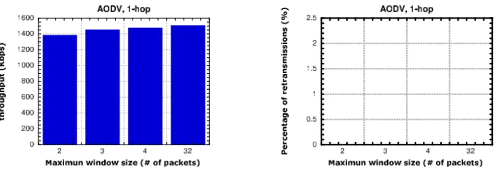
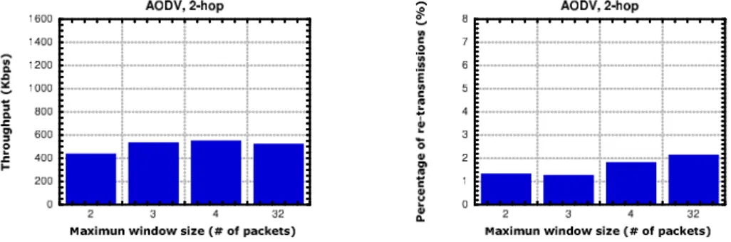
16.5.1 Influence of the maximum congestion window size . . . 135
16.5.2 Influence of Hello messages . . . 139
16.5.3 Influence of the background traffic . . . 141
16.5.4 Analysis with OLSR routing protocol . . . 142
16.5.5 Conclusions . . . 142 16.6 TPA VS. TCP . . . 143 16.6.1 Chain Topology . . . 143 16.6.2 Cross Topology . . . 155 16.6.3 Roaming Node . . . 157 16.7 Conclusions . . . 160
CONTENTS 1
17 Simulative Analysis of TPA 163
17.1 Introduction . . . 163
17.2 Performance Measures . . . 164
17.3 TCP with Adaptive Pacing . . . 165
17.4 Cross and Parallel Topology . . . 166
17.5 Grid Topology . . . 169
17.6 Static Random Topology . . . 172
17.7 Mobile Scenario . . . 173
17.8 Conclusions . . . 175
18 Conclusion 176
Chapter 1
Introduction
1.1
Mobile Ad hoc Networks
A Mobile Ad hoc Network (MANET) is a collection of mobile nodes connected together over a wireless medium, which self-organize into an autonomous multi-hop wireless network. Nodes in ad hoc networks work as both hosts and routers, and so each node is able to forward data for its neighbors. This model design is needed because each node counts on a limited transmission range to reach its intended destination node. Hence, when a given node have data to send to another node that is not in its transmission range, it uses one of its neighbors to forward the data toward the destination. This process may involve multiple intermediate nodes, and it may produce the establishing of a multihop con-nection (multi-hop ad hoc network) between sender and receiver, as depicted in Figure 1.1. These networks are appropriate for scenarios in which wired networks are not possible or not desirable such as disaster recovery, battlefield, short-lived networks as in conference spots, etc. In addition, in the last few years MANETs are also emerged as a flexible and low-cost extension of wired infrastructure networks.
MANETs inherit the traditional problems of wireless communication and wireless networking, like high bit error rate, high sensitivity of wireless channel from outside signals, the possibility of path asymmetry, and so on. In addition, the multihop nature of connections, the lack of a fixed infrastructure, and nodes mobility add new problems, such as network partitions, route failures, and the hidden (or exposed) terminal. These new problems pose a number of design constraints that are specific to ad hoc networking.
Research on MANETs spanned a large number of issues. Transport proto-cols, roting protocols and MAC protocols are active fields of research. In the first place, this thesis examines the problem of interconnect Ad hoc network to Internet, and presents a practical architecture to logically extend traditional wired LANs using multi-hop ad hoc networking technologies. In the second place, this thesis presents the problems encountered by TCP when it operates over multi-hop ad hoc networks, and proposes a novel transport protocol for
CHAPTER 1. INTRODUCTION 3
Figure 1.1: Multi Hop path between two communicating nodes.
ad hoc networks, named TPA, that is specifically tailored to the characteristics of the MANET environment. All the proposed solutions have been prototyped and evaluated in a real ad hoc testbed, as well as using the ns-2 simulator [3]. In the following, I briefly present the problems and the solutions that I studied during my Ph.D.
1.2
Problems Statement and Proposed Solutions
The recent advances in mobile and ubiquitous computing, and the development of inexpensive, portable devices are extending the application fields of ad hoc networking. Mobile users are looking for multi-purpose networking platforms in which cost is an issue and Internet access is a must. As a consequence, nowa-days, multi-hop ad hoc networks do not appear only as isolate self-configured networks, but also emerge as a flexible and low-cost extension of wired infras-tructure networks, coexisting with them. A new class of networks is emerging from this view, in which a mix of fixed and mobile nodes interconnected via het-erogeneous (wireless and wired) links forms a multihop hethet-erogeneous ad hoc network integrated into classical wired/wireless infrastructure-based networks. Three different categories of solutions have been proposed for enabling in-terconnection between ad hoc networks and the Internet. One approach uti-lizes the Network Address Translation (NAT) mechanism, implemented on each gateway that interconnect the ad hoc network with the wired infrastructure net-work. With this approach, the mobile nodes do not need a globally routable IP address because the NAT gateway translates the source private IP address of outgoing traffic with a public IP address, which is routable on the fixed In-ternet. An alternative approach relies on the design of techniques capable of automatically configuring a unique, topology-dependent and globally routable IP address for each mobile node visiting an ad hoc network (IPv6 based solu-tions). Finally, a third category of solutions assumes that a Mobile IP Foreign Agent is implemented in the ad hoc nodes that act as Internet gateways. With
this approach, the mobile nodes need a permanent and unique globally routable IP address (i.e., their home address), which is used during the registration pro-cedures with the foreign agents of the visiting ad hoc network.
However, all the solutions that have been proposed in literature have a number of disadvantages. For example, the Mobile IP based solutions have several drawbacks. The first is that, in order to allow Mobile IP and ad hoc networking to cooperate, it is needed to introduce further complexities and sub-optimal operations in the implementations of both Mobile IP and ad hoc routing protocols. In addition, Mobile IP was designed to handle mobility of devices in case of relatively infrequent mobility. Thus, the overheads introduced to manage roaming and handoffs between foreign agents are a relevant issue in MANETs. Finally, when the technique of default routes is used to route the traffic from the mobile nodes to the closest gateway, the use of Mobile IP can easily lead to triangle routing. In fact, when the mobile node moves, it can get closer to a gateway different from the one to which it is currently registered. As a consequence, the forward traffic leaves the ad hoc network through one gateway, while the return traffic enters the ad hoc network through the new gateway to which the mobile node is registered. To solve this problem, some authors propose not to use default routes. They instead propose to use Mobile IP reverse tunnelling [69], or explicit tunnelling to one of the gateway used to leave ah hoc network. However, the tunnelling mechanism introduces a non negligible overhead in the communication between nodes.
Also the NAT based solutions have some drawbacks. For example, they encounter problems in multi-homed networks, i.e., when multiple gateways are present in the ad hoc network. Indeed, to avoid transport-layer session breaks, it is necessary to ensure that each packet from the same session is routed over a specific gateway, since a NAT router translates both outgoing and incoming packets. To solve this problem, some NAT based solutions adopts the IP-in-IP encapsulation mechanism to tunnel the packets towards the desired gateway. Employing explicit tunnelling ensures that each packet of the same transport-layer session is consistently routed through the same gateway, even if the source node moves. However, it introduces a non negligible overhead in every packet sent. In addition, NAT is not very suitable for incoming connections and this fact causes significant difficulties for peer-to-peer applications.
These observations motivated me to study an alternative, and more efficient and lightweight solution to provide Internet connectivity for ad hoc networks. Specifically, in the first part of my Ph.D. activity, I investigated how MANETs can be used to extend the range of traditional Wireless Local Area Networks (WLANs) [4] over multiple radio hops, in order to provide seamless and unteth-ered mobility support for mobile/portables devices in the local area environ-ment. In my work, I envisaged an heterogeneous network environment in which wired and multi-hop wireless technologies transparently coexist and interoper-ate (see Figure 1.2). In this network, separinteroper-ated groups of nodes without a direct access to the networking infrastructure form ad hoc islands, establishing multi-hop wireless links. Special nodes, hereafter indicated as gateways, having both wired and wireless interfaces, are used to build a wired backbone
inter-CHAPTER 1. INTRODUCTION 5
Figure 1.2: Envisaged an heterogeneous network environment.
connecting separated ad hoc components. In addition, the gateways use their wired interfaces also to communicate with static hosts belonging to a wired LAN. The network resulting from the integration of the ad hoc network with the wired LAN is an extended LAN, in which static and mobile hosts transpar-ently communicate using traditional wired technologies, or ad hoc networking technologies.
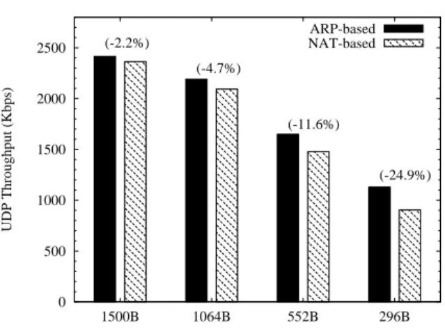
The solution I presented during my Ph.D. [24, 23, 21, 20, 22] is a simple yet practical approach that relies only on basic ARP capabilities [103] and standard IP routing rules to logically extend a wired LAN. In addition, my solution includes a distributed protocol for the address autoconfiguration of ad hoc nodes. This protocol relies on DHCP servers located in the wired part of the network, and it does not require that new ad hoc nodes have direct access to the DHCP servers. Using my scheme, mobile nodes can dynamically obtain a unique IP address that is topologically correct within the extended LAN. During my Ph.D., I have also prototyped the main components of my architec-ture in a general and realistic test-bed. Using this test-bed, I have conducted a large variety of experiments, comparing the throughput performance of In-ternet access provided by my proposed scheme and an alternative well-known NAT-based solution [48]. The shown experimental results demonstrate that: i) my scheme ensures higher per-connection throughputs than the NAT-based solution, ii) node mobility does not cause permanent transport-layer session breaks, iii) node mobility induces drastic throughput degradations when using the NAT-based solution, while my proposed technique performs more efficient gateway handoffs, and iv) the network performances can be significantly im-proved by properly setting the routing protocol parameters such as to increase route stability.
In this thesis I also analyse the problems encountered by TCP when it operates over MANETs. Research on efficient transport protocols for ad hoc networks is one of the most active topics in the MANET community. Such a great interest is basically motivated by numerous observations showing that, in general, TCP is not able to efficiently deal with the unstable and very dy-namic environment provided by multi-hop ad hoc networks. This is because some assumptions, in TCP design, are clearly inspired by the characteristics of wired networks dominant at the time when it was conceived. More specifically, TCP implicitly assumes that packet loss is almost always due to congestion phenomena causing buffer overflows at intermediate routers. Furthermore, it also assumes that nodes are static (i.e., they do not change their position over time). Unfortunately, these assumptions do not hold in MANETs, since in this kind of networks packet losses due to interference and link-layer contentions are largely predominant, and nodes may be mobile.
Many papers have pointed out that the drastic differences between MANETs and the legacy Internet may lead to poor performance of TCP over MANETs. However, almost all these studies rely on simulation, and many of them do not consider some important details (e.g., the routing protocol is often omitted). To the best of my knowledge, very few experimental analyses have been carried out so far [57, 71]. On the other side, previous experimental studies have shown that certain aspects of real MANETs are often not effectively captured in simu-lation tools [14]. Furthermore, available software and hardware products often use parameters settings different from those commonly assumed in simulation tools. Finally, real operating conditions are often different from those modeled in simulation experiments. For example, interferences caused by WiFi hotspots or other devices in the proximity are inevitable in practice. For all the above reasons, I spent some time to analyse TCP performance in a real testbed, us-ing a network havus-ing a chain topology with variable length, and usus-ing different routing protocols [19]. My experimental outcomes are normally aligned with simulation results, and they show that TCP performance in multi hop ad hoc networks is sub-optimal and strong depends on the link quality and on the routing protocol parameters. In addition, I also found some results contrasting with simulation. Specifically, I discovered that in a real world the TCP optimal operating point moves with respect to that measured by simulation.
To address the problems experienced by TCP in MANETs, a number of proposals have been presented. The vast majority of these proposals are TCP modifications that address some particular TCP inefficiency. The main design requirement is indeed to keep the improved transport protocol backward com-patible with the legacy TCP, so that “improved” and “legacy” users may be able to communicate with each other. While I acknowledge the importance of TCP compatibility, int his thesis I advocate a different approach. The dif-ferences between MANETs and traditional wired networks are so many, that TCP would need a large number of modifications to work in this environment. Consequently, it might be worth to design a transport protocol from scratch, without worrying too much – at the design stage – about backward compati-bility with the legacy TCP. Interoperacompati-bility with TCP could be implemented
CHAPTER 1. INTRODUCTION 7
at a later stage, as a single and coherent patch to the new protocol. Follow-ing this approach, the last activity of my Ph.D. consisted in the design of a new transport protocol named Transport Protocol for Ad hoc networks (TPA) [13], specifically tailored to the MANETs characteristics. TPA is a lightweight transport protocol that provides a connection-oriented, reliable type of service. It differs from TCP in a number of ways. Specifically, the data transfer and the congestion control algorithms have been re-designed. Furthermore, TPA explicitly detects and deals with both route failures and route changes. TPA can leverage cross-layer interactions with the routing protocol, when available. For example, it is able to intercept and interpret route failure and route re-establishment messages. However, TPA works also with routing protocols that do not provide this type of information.
This thesis reports the complete description of TPA protocol. In addition, it reports the results of a performance analysis of TPA [17, 18, 16]. Differ-ently from the most of the researches on ad hoc networks, that realize only on simulation analysis, this thesis reports the analysis of TCP and TPA perfor-mance in a real, as well as, in a simulation environment. Specifically, I used real word experiments to compare TCP and TPA performance over a wide range of reproducible network topology, like the string and the cross topology. I also used real word experiments to analyse TCP and TPA performance in a very simple but realistic mobile scenario, like the roaming node scenario. The obtained results show that TPA always outperforms TCP. Specifically, TPA throughput is between 5% and 19% greater than the TCP throughput, and, furthermore, TPA retransmits between 64% and 94% less data segments. I in-stead used simulative analysis to study TPA performance over simple network topologies, like the cross and the paralles topologies, and over more complex network topologies, like the grid topology and a random topology (50 nodes randomly distributed in a area A=1000m × 1000m). I also analysed TPA per-formance over a highly dinamic environment, where 50 nodes move over a 1000 x 1000 area. The simulative show that TPA is able to achieve an increment in throughput up to 6%, and an increment in fairness up to 34% respect to TCP. To conclude TPA study, I used a simulative analysis to study the well-known unfairness problems among concurrent connections that affects TCP as well as TPA. I integrated in TPA the Adaptive Pacing mechanism, a popular proposal for improving TCP fairness [46], and I showed that TPA with Adaptive Pacing outperforms TCP with Adaptive Pacing. In all cases I have investigated, TPA is able to improve the performance of TCP. Specifically, TPA delivers greater throughput with respect to TCP (up to 39% increase), while granting an increment in fairness up to 5.6% respect to TCP. In addiction, TPA is able to reduce the number of retransmitted segment up to 78.7%.
1.3
Structure of the document
This thesis is structured into three parts. In the first part I present background information for each of the areas I have explored. Part I includes an overview
of the Transmission Control Protocol (TCP), and some of its main variants and extentions. It also includes a review of the main features of MANETs, introducing the IEEE 802.11 architecture and protocols, and providing back-ground information on routing protocols for MANETs, with a special attention on the Ad hoc On-demand Distance Vector (AODV) protocol and on the Op-timised Link State Routing (OLSR) protocol. Finally, Part I briefly describes some mechanisms and protocols used in Part II, like the Mobile IP Protocol, the Address Resolution Protocol (ARP), and the Network Address Translation (NAT) mechanism.
In the second Part, I describe the activity about the interconnection between ad hoc networks and Internet. Part II first discusses the variety of architectural issues and design options that need to be considered to interconnect ad hoc networks to fixed IP networks. Then it introduces existing approaches to tackle the internetworking of MANETs with the fixed Internet and reviews the most well known solutions. Finally, Part II describes the design principles and the protocol details of my proposed solution, and shows experimental results on the network performance in various test-bed configurations.
In the third Part, I describe my activity about the study of TCP perfor-mance over MANETs. Part III first describes the main specificity of MANETs that condition TCP behaviour and also discusses the major proposal aimed to improve TCP’s performance in such environment. Then, it reports the com-plete description of TPA features, and also reports the description of TPA prototype implementation. Finally, Part III reports the results of the analysis of TCP and TPA performance in a real, as well as, in a simulation environment.
Part I
Preliminary Information
Chapter 2
Introduction
This Part presents preliminary information and concepts that will be used in the rest on the thesis. It is organized as follow. Chapter 5 presents an overview of the Transmission Control Protocol (TCP), and also presents some of its variants and extentions. Chapter 3 reviews the main features of MANETs, introducing the IEEE 802.11 architecture and protocols. Chapter 4 provides background information on routing protocols for MANETs, focusing special attention on the Ad hoc On-demand Distance Vector (AODV) protocol and on the Optimized Link State Routing (OLSR) protocol, that was been used in the thesis activity. Finally, Chapter 6 briefly describes some mechanisms and protocols used in the first part of this thesis, like the Mobile IP Protocol, the Address Resolution Protocol (ARP), and the Network Address Translation (NAT) mechanism.
Chapter 3
IEEE 802.11 Architecture
and Protocols
This section focuses on the IEEE 802.11 architecture and protocols as defined in the original standard [2], with a particular attention to the MAC layer. The IEEE 802.11 [2] is the standard for Ad hoc networks, and it specifies both the MAC and the Physical layer. The MAC layer offers two different types of service: a contention free service provided by the Distributed Coordination Function (DCF), and a contention-free service implemented by the Point Co-ordination Function (PCF). These service types are made available on top of a variety of physical layers. Specifically, three different technologies have been specified in the standard: Infrared (IF), Frequency Hopping Spread Spectrum (FHSS) and Direct Sequence Spread Spectrum (DSSS).
The DCF provides the basic access method of the 802.11 MAC protocol and is based on a Carrier Sense Multiple Access with Collision Avoidance (CSMA/CA) scheme. The PCF is implemented on top of the DCF and is based on a polling scheme. It uses a Point Coordinator that cyclically polls stations, giving them the opportunity to transmit. Since the PCF can not be adopted in ad hoc mode, it will not be considered hereafter.
3.1
Distributed Coordination Function (DCF)
According to the DCF, before transmitting a data frame, a station must sense the channel to determine whether any other station is transmitting. If the medium is found to be idle for an interval longer than the Distributed Inter-Frame Space (DIFS), the station continues with its transmission (see Figure 3.1). To guarantee fair access to the shared medium, a station that has just transmitted a packet and has another packet ready for transmission must per-form the backoff procedure before initiating the second transmission. On the other hand, if the medium is busy the transmission is deferred until the end of the ongoing transmission. A random interval, henceforth referred to as the
backoff time, is then selected, which is used to initialize the backoff timer. The backoff timer is decreased for as long as the channel is sensed as idle, stopped when a transmission is detected on the channel, and reactivated when the channel is sensed as idle again for more than a DIFS. The station is enabled to transmit its frame when the backoff timer reaches zero. For example, the backoff timer of Station 3 in Figure 3.1 is disabled while Station 2 is transmit-ting its frame; the timer is reactivated a DIFS after Station 2 has completed its transmission. The backoff time is slotted. The backoff time is an integer number of slots uniformly chosen in the interval (0, CW-1 ). CW is defined as the Backoff Window, also referred to as Contention Window. At the first transmission attempt CW = CWmin, and it is doubled at each retransmission
up to CWmax. In the standard CWmin and CWmax values depend on the
physical layer adopted. For example, for the FHSS Physical Layer CWminand
CWmaxvalues are 16 and 1024, respectively [2].
Figure 3.1: Basic Access Method.
Obviously, it may happen that two or more stations start transmitting simultaneously and a collision occurs. In the CSMA/CA scheme, stations are not able to detect a collision by hearing their own transmissions (as in the CSMA/CD protocol used in wired LANs). Therefore, an immediate positive acknowledgement scheme is employed to check the successful reception of a frame. Specifically, upon reception of a data frame, the destination station initiates the transmission of an acknowledgement frame (ACK) after a time interval called Short InterFrame Space (SIFS). The SIFS is shorter than the DIFS (see Figure 3.2) in order to give priority to the receiving station over other possible stations waiting for transmission. If the ACK is not received by the source station, the data frame is presumed to have been lost, and a retransmission is scheduled. The ACK is not transmitted if the received packet is corrupted. A Cyclic Redundancy Check (CRC) algorithm is used for error
CHAPTER 3. IEEE 802.11 ARCHITECTURE AND PROTOCOLS 13
detection.
Figure 3.2: ACK generation.
After an erroneous frame is detected (due to collisions or transmission er-rors), a station must remain idle for at least an Extended InterFrame Space (EIFS) interval before it reactivates the backoff algorithm. Specifically, the EIFS shall be used by the DCF whenever the physical layer has indicated to the MAC that a frame transmission was begun that did not result in the correct reception of a complete MAC frame with a correct FCS value. Reception of an error-free frame during the EIFS re-synchronizes the station to the actual busy/idle state of the medium, so the EIFS is terminated and normal medium access (using DIFS and, if necessary, backoff) continues following reception of that frame.
3.2
Common Problems in Wireless Ad Hoc
Net-works
This section discusses some problems that can arise in wireless networks, mainly in the ad hoc mode. The characteristics of the wireless medium make wireless networks fundamentally different from wired networks. Specifically, as indi-cated in [2]:
• the wireless medium has neither absolute nor readily observable bound-aries outside of which stations are known to be unable to receive network frames;
• the channel is unprotected from outside signals;
• the wireless medium is significantly less reliable than wired media; • the channel has time-varying and asymmetric propagation properties. In wireless (ad hoc) network that relies upon a carrier-sensing random access protocol, like the IEEE 802.11 DCF protocol, the wireless medium character-istics generate complex phenomena such as the hidden-station and exposed-station problems. Figure 3.3 shows a typical hidden exposed-station scenario. Let us assume that station B is in the transmitting range of both A and C, but A and
C cannot hear each other. Let us also assume that A is transmitting to B. If C has a frame to be transmitted to B, according to the DFC protocol, it senses the medium and finds it free because it is not able to hear A’s transmissions. Therefore, it starts transmitting the frame but this transmission will results in a collision at the destination Station B.
Figure 3.3: Hidden Station.
The hidden station problem can be alleviated by extending the DCF basic mechanism by a virtual carrier sensing mechanism that is based on two control frames: Request To Send (RTS) and Clear To Send (CTS), respectively. Ac-cording to this mechanism, before transmitting a data frame, the station sends a short control frame, named RTS, to the receiving station announcing the upcoming frame transmission (see Figure 3.4). Upon receiving the RTS frame, the destination station replies by a CTS frame to indicate that it is ready to receive the data frame. Both the RTS and CTS frames contain the total dura-tion of the transmission, i.e., the overall time interval needed to transmit the data frame and the related ACK. This information can be read by any listening station that uses this information to set up a timer called Network Allocation Vector (NAV). While the NAV timer is greater than zero the station must re-frain from accessing the wireless medium. By using the RTS/CTS mechanism, stations may become aware of transmissions from hidden station and on how long the channel will be used for these transmissions.
Figure 3.5 depicts a typical scenario where the exposed station problem may occur. Let us assume that both Station A and Station C can hear transmis-sions from B, but Station A can not hear transmistransmis-sions from C. Let us also assume that Station B is transmitting to Station A and Station C receives a frame to be transmitted to D. According to the DCF protocol, C senses the medium and finds it busy because of B’s transmission. Therefore, it refrains from transmitting to C although this transmission would not cause a collision at A. The exposed station problem may thus result in a throughput reduction. However, even with the RTS/CTS mechanism enabled, the hidden termi-nal problems still exist [55, 128]. Figure 3.6 depicts a typical scenario where the hidden and exposed terminal problems may occur in the presence of the RTS/CTS mechanism. Let us assume that node C is transmitting to station D and node A want to transmit a frame to station B. Node A, according to
CHAPTER 3. IEEE 802.11 ARCHITECTURE AND PROTOCOLS 15
Figure 3.4: Virtual Carrier Sensing Mechanism.
the DFC protocol, senses the medium and finds it free because it is not able to hear C’s transmissions. Therefore, it starts transmitting the RTS frame but this transmission will results in a collision at the destination Station B. Even if the collision doesn’t happen, node B cannot reply to node A, since it has the NAV set. Also node F cannot communicate to node E, since node E has its NAV set.
Figure 3.6: Hidden and Exposed Station in the presence of the RTS/CTS mechanism.
The explanation above is a very simplified way of describing the hidden node and exposed node problems. The actual propagation model of 802.11 counts on three communication ranges: the Transmission Range, the Interference Range, and the Physical Carrier Sensing Range. The Transmission Range is the range (with respect to the transmitting station) within which a transmitted packet can be successfully received. It is mainly determined by the transmission power and the radio propagation properties. The Physical Carrier Sensing Range is the range (with respect to the transmitting station) within which the other sta-tions detect a transmission. It mainly depends on the sensitivity of the receiver (the receive threshold) and the radio propagation properties. The Interference Range is the range within which stations in receive mode will be “interfered with” by a transmitter, and thus suffer a loss. The interference range is usu-ally larger than the transmission range, and smaller then the Physicall Carrier Sensing Range. It is a function of the distance between the sender and receiver, and of the path loss model. It is very difficult to predict the interference range as it strongly depends on the ratio between power of the received “correct” signal and the power of the received “interfering” signal. Both these quantities heavily depend on several factors (i.e., distance, path, etc.) and hence to esti-mate the interference is needed a detailed snapshot of the current transmission and relative station position. In simulation studies the following relationship has been generally assumed:
T X range ≤ IF range ≤ P CS range
For example, in the ns-2 simulation tool [3] the following values are used to model the characteristics of the physical layer:
Chapter 4
Routing Protocols for
MANETs
Development of routing protocols for ad hoc networks has been one of the hottest topics within this area in recent years. As a consequence, a large number of routing protocols have been designed, either by modifying Internet routing protocols, or proposing new routing approaches [101, 89, 100, 68, 58, 37, 38, 78, 75, 81, 134, 123, 94]. In the following, I present a high-level classification of MANET routing protocols, and then I describe the two routing protocol used in my thesis.
MANET routing protocols are typically subdivided into two main cate-gories [25]: proactive routing protocols [101, 89, 100] and reactive on-demand routing protocols [100, 68]. Proactive routing are derived from the traditional distance vector and link state protocols developed for Internet. The primary characteristic of proactive approaches is that each node in the network main-tains a route to every other node in the network at all times. Route creation and maintenance is accomplished through some combination of periodic and event-triggered routing updates. This approach have the advantage that routes are available at the moment they are needed. A source can simply check its routing table, when it has data packets to send to some destination, and begin packet transmission. However, the primary disavantage of these protocols is that the control overhead can be significant in large. Further, the amount of routing state maintained at each node scales as O(n), where n is the number of nodes in the network.
Reactive on demand routing protocols take a very different approach than proactive protocols, since they do not maintain a route between all pairs of network nodes. Instead, reactive protocols discover the route to a destination only when there is a demand for it. Specifically, when a source node needs to send date packets to some destination, it checks its routing table to deter-mine whether it has a route. If no route exists, it performs a route discovery procedure to find a path to the destination. Hence, route discovery becomes on-demand. With this approach, if two nodes never need to talk to each other,
then nodes in the network do not need to utilize their resources maintaining a path between each other. The benefit of this approach is that signalling overhead is likely to be reduced compared to proactive approaches, particu-larly in networks with low to moderate traffic load. When the number of data sessions in the network becomes high, then the overhead generated by the re-active routing protocols may even surpass that of the prore-active approaches. The drawback of reactive approaches is the introduction of a route acquisition latency. That is, when a route is needed by a source node, there is some finite latency while the route is discovered. In contrast, with a proactive approach, routes are typically available at the moment they are needed.
4.1
Ad hoc On-demand Distance Vector
(AODV)
The Ad hoc On-Demand Distance Vector (AODV) [100] is a well know reactive routing protocol. With this protocol, each node maintains a routing table in which next hop routing information for destination nodes is stored. Each routing table entry has an associated lifetime value to expire the route if it is not utilized within the lifetime period. In addition, every node under AODV keeps two counters: a node sequence number and a broadcast ID. These counters are used for loop freedom, duplicates detection, and for ensuring selection of the most recent routing path.
When a node has data packets to send to some destination, it first checks its routing table to determine whether it already has a route to the destination. If such a route exists, it can use that route for packet transmissions. Otherwise, it must initiate a route discovery procedure to find a route. A node starts route discovery by broadcasting a route request (RREQ) packet to its neighbors. The receiving neighbors forward the RREQ to their neighbors and so on, until the packet reaches either the destination itself or an intermediate node that contains a fresh enough table entry pointing to the destination.
When a neighboring node receives a RREQ, it first creates a reverse route to the source node. Then it checks whether it has an unexpired route to the destination. If it does not have a valid route to the destination, it simply rebroadcasts the RREQ to it neighbors. In this manner, the RREQ floods the network in search of a route to the destination. Instead, if the node has a valid route to the destination, then it checks if its routing table entry is at least as recent as the source node’s last known route to the destination (see [100] for details). This condition also guarantees loop freedom. If this condition is met, the node can create a route replay (RREP) message. After creating the reply, the node unicasts the message to its next hop towards the source node. Thus, the reverse route that was created by the RREQ is utilized to forward the RREP back to the source node.
When the next hop receives the RREP, it first creates a forward route entry for the destination node, using the node from which it received the RREP as the next hop toward the destination. Once the node has created the forward
CHAPTER 4. ROUTING PROTOCOLS FOR MANETS 19
route entry, it forwards the RREP to the source node. The RREP is thus forwarded hop by hop to the source node. Once the source node receives the RREP, it can utilize the created path for the transmission of data packets.
Once a route is established, it must be maintained as long as it is needed (a route that has been recently utilized for the transmission of data packets is called an active route). Node mobility and link layer contention may produce link break along the path followed by the route. Breaks on links that are not being utilized for the transmission of data packets do not require any repair. Breaks in active routes, instead, must be quickly repaired. When a link break along an active route occurs, the node upstream of the break invalidates the routes to each of those destinations in its routing table passing through the broken link. It then creates a route error (RERR) message. This message lists all of the destinations that are now unreachable due to the loss of the link. After creating the RRER message, the node sends the RERR message to its upstream neighbors that were also utilizing the broken link. These nodes, in turn, invalidate the broken routes and send their own RRER messages to their upstream neighbors that were utilizing the link. The RERR message thus traverses the reverse path to the source node. Once the source node receives the RERR, it can perform a new RREQ to repair the route, if it is still needed. An optimization of AODV is the the local repair of link breaks in active routes. When a link break occurs, instead of sending a RERR message back to the source, the node upstream of the break can try to repair the link locally itself. If successful, fewer data packets are dropped because the route is repaired more quickly. If the local repair attempt fails, a RERR message is sent to the source node as previously described.
An important feature of AODV is that it can use two different mechanisms for neighbour discovery and local connectivity maintenance, i.e., link layer feed-back information provided by the underlying MAC protocol, or Hello mes-sages. Hello messages are periodic broadcast messages that are utilized by each node to announce its presence in the one-hop neighbourhood. In AODV, Hello messages and broadcast messages can server the same function. For example, RREQ messages are broadcast IP packets; therefore, reception of a RREQ indicates the presence of a link. Hence, the term Hello message is used to loosely refer to all broadcast control messages. In AODV, reception of a Hello message indicates bidirectional connectivity to the sender. Once a link is established, failure to receive several Hello messages from a neighbour indicates a loss of connectivity. When Hello messages are used, each node broadcasts Hello messages at least once every HELLO INTERVAL sec-onds. Failure to receive a Hello message for ALLOW ED HELLO LOSS ∗ HELLO IN T ERV AL seconds indicates a loss of connectivity to that neigh-bour.
In contrast to Hello messages, link layer feedback is able to quickly identify link failures during transmission of a data packet to another node. This feed-back must be provided by the underlying MAC protocol, i.e. the IEEE802.11 MAC protocol. In IEEE 802.11, a unicast packet is first queued for trans-mission at the MAC layer. If the packet cannot be transmitted after multiple
MAC layer retries, an indication is given to the higher layers, that a failure has occurred. This results in immediate notification of a broken link as soon as a packet fails to be transmitted.
4.2
Optimized Link State Routing (OLSR)
The OLSR protocol [37] is an optimization of the classical link state algorithm tailored to mobile ad hoc networks. More precisely, being a proactive routing protocol, OLSR periodically floods the network with route information, so that each node can locally build a routing table containing the complete information of routes to all the nodes in the ad hoc network running the OLSR protocol. The OLSR routing algorithm employs an efficient dissemination of the network topology information by selecting special nodes, the multipoint relays (MPRs), to forward broadcast messages during the flooding process. More precisely, each node independently selects its multipoint relays among its one-hop neigh-bours such as to ensure that all its two-hop neighneigh-bours receive the broadcast messages retransmitted by these selected relays. The link state reports, which are generated periodically by MPRs, are called Topology Control (TC) messages. These TC messages are flooded to all the nodes in the network, but only the MPRs are allowed to forward the control messages received from other nodes, in order to reduce the number of retransmissions needed to cover the entire network.
OLSR employs a neighbour discovery procedure based on Hello messages. The Hello packets contain the list of neighbours known to the node and their link statuses. Thus, Hello messages allow each node to discover its one-hop neighbours, as well as its two-hop neighbours, which are needed during the MPR selection procedure. The neighbourhood information and the topology information are updated periodically, and they enable each node to locally com-pute the least-cost routes to any possible destination in the ad hoc network, by using the Dijkstra’s shortest path algorithm. This routing table is recom-puted whenever there is a change in either the neighbourhood information or the topology information.
In order to enable the injection of external routing information into the ad hoc network, the OLSR protocol defines the Host and Network Associ-ation (HNA) message. The HNA message binds a set of network prefixes to the IP address of the node attached to the external networks, i.e., the gate-way node. Consequently, each ad hoc node is informed about the network address and netmask of the network that is reachable through each gateway. In other words, the OLSR protocol exploits the mechanism of default routes to advertise Internet connectivity. For instance, a gateway that advertises the conventional default route 0.0.0.0/0, will receive each packet destined to IP addresses without a known route on the local ad hoc network.
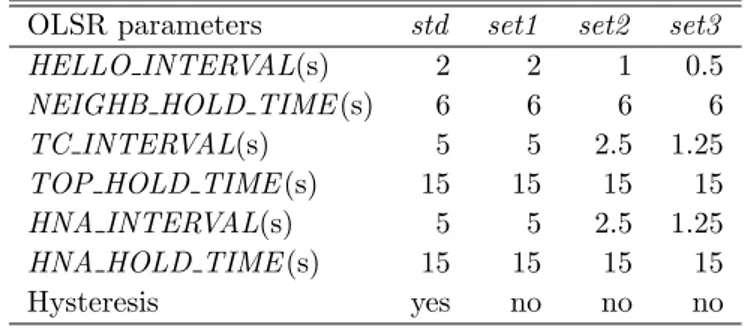
The periodic exchange of OLSR control packets is regulated by a set of parameters that establish the timing for the OLSR operations. These pa-rameters define the generation period of each control packet and the
valid-CHAPTER 4. ROUTING PROTOCOLS FOR MANETS 21
ity time related to the information provided with the control packet. The default constant values for these parameters are defined in the OLSR RFC [37]. For example, Hello messages are generated by each node with period equal to HELLO Interval, and the information provided in Hello messages is considered valid for a NEIGHB HOLD TIME. The TC messages, instead, are generated by the each MPRs every TC Interval, and their validity time is TOP HOLD TIME. Finally, each gateway being connected to external net-works, generates HNA messages every HNA Interval, and their information is valid for HNA HOLD TIME.
Chapter 5
Transmission Control
Protocol
Transmission Control Protocol (TCP) is the de facto standard for reliable connection-oriented transport protocols, and is normally used over IP (Internet Protocol) to provide end-to-end reliable communications to Internet applica-tions. TCP provides a reliable, connection-oriented, and full duplex type of service. In addition, TCP implements both flow control and congestion con-trol mechanisms. The former prevents the TCP receiver’s buffer from being overflowed. The second is an end-to-end congestion control mechanism, that prevents process to inject into the network an excessive traffic load.
This chapter introduces TCP and discusses the main concepts and mecha-nisms associated with it. In addition it describes some TCP variants, like TCP Reno, TCP NewReno, TCP Sack, and TCP Vegas. Moreover, it introduces some TCP extentions, like Delayed Acknowledgments (DA), Explicit Conges-tion NotificaConges-tion (ECN) and Limited Transmit.
5.1
TCP Segment Structure
The TCP segment consists of an header field and a data field. The data field contains a chunk of application data. The MSS (Maximum Segment Size) limits the maximum size of a segment’s data field. When TCP sends a large file it typically breaks the file into chunks of size MSS. However, the size of the data field can be smaller that MSS. For example with application like Telnet, the data field in the TCP segment is often only one byte. The smallest TCP header is composed of 20 bytes, but if options are used then its size may be as large as 60 bytes. TCP options are used to allow a TCP connection to carry different control fields without changing the structure of the basic header. These options are defined at the beginning of the connection between sender and receiver.
Figure 5.1 shows the structure of the TCP segment. The header includes the following fields:
CHAPTER 5. TRANSMISSION CONTROL PROTOCOL 23
Figure 5.1: TCP header.
• Source and Destination port number fields: these fields are used for multi-plexing/demultiplexing data from/to upper layer applications. These two values combined with the source and destination fields in the IP header, uniquely identify each connection.
• Sequence Number field : TCP views data as an unstructured, but ordered stream of bytes. The sequence number field is the byte-stream number of the first byte in the segment. This 32-bit fields is used by TCP to implement a reliable data transfer service, as discussed in Section 5.3. • Acknowledgment Number field : TCP is full-duplex. This means that an
host A may be receiving data from host B while it sends data to host B (as part of the same TCP connection). Each of the segments sent by host B have a sequence number for the data flowing from B to A. The acknowledgment number that host A puts in its segment is the sequence number of the next byte host A is expecting from host B. This 32-bit fields is used by TCP to implement a reliable data transfer service, as discussed in Section 5.3.
• Header Length field : This field specifies the length of the TCP header in 32-bits words. The TCP header can be of variable length due to the TCP option field. By having 4 bits, this field limits the header size to 60 bytes. The length of a TCP header with no options set is 20 bytes. • Reserved field : This fields was reserved for future use. For example,
some bits of this field are used by the Explicit Congestion Notification mechanism [104, 108].
• Flag field : This fields contains 6 bits. The URG bit specifies that the Urgent Pointer filed is valid (there is data in the segment marked as “urgent”). The ACK bit indicates that the value carried out in the acknowledgment number field is valid. The PSH bit indicates to the receiver that it should pass the data to the upper layer immediately. The RST bit resets the connection. The SYN and FIN bits are used for connection setup and teardown (see Section 5.2).
• rcvr window size field : This field contains the size of the receiver window, which defines the number of bytes the TCP receiver is willing to accept from the sender (see Section 5.4).
• Checksum field : This field is used for error detection. It is calculated by the sender considering not only the header but also the data field. The receiver may check the data integrity by checking this field.
• Urgent Pointer field : This field is valid only if the URG flag is set. It specifies a part of the data filed that must be sent quickly to the receiver. • Options Field : This field is used by a sender and receiver pair to negotiate TCP options, such as the maximum segment size (MSS), timestamps, Window Scale Option, etc.
5.2
TCP Connection Management
TCP is a connection oriented transport protocol. This means that before one application process can being to send data to another, the two processes must first perform an handshake to open a TCP connection with each other. During the TCP connection establishment, both sides of the connection will initialize many TCP “state variables” associated with the TCP connection. The connec-tion state resides entirely in the two end systems. The intermediate network elements do no maintain TCP connection state.
A TCP connection provides for full duplex data transfer. If there is a TCP connection between process A and B, the application-level data can flow from A to B and from B to A at the same time. A TCP connection is also always point-to-point, that is, between a single sender and a single receiver. Multicasting is not possible with TCP.
Now, I will briefly describe the procedures used by TCP to setup and tear-down a connection.
5.2.1
Connection Setup and teardown
To establish the connection, either end nodes (hosts) may start the procedure by sending a request packet to the opposed side. The full procedure is com-monly referred to as “three-way handshake” since it involves the exchange of three packets in total. The end node starting the connection establishment is called client host and the other side is the server host. The three-way hand-shake makes use of the SYN flag (1 bit) in the TCP header to mark the packets used exclusively for connection setup reasons. Figure 5.2 illustrates the three-way handshake’s exchanges [41].
The client host first sends a special segment to the server host requesting a connection setup. This segment is generally named SYN segment and does not contain any data. It only contains the header with the SYN flag set to one and the desired initial sequence number X. Provided that the server host is able to accept the connection, it allocates the TCP buffers and variables associated
CHAPTER 5. TRANSMISSION CONTROL PROTOCOL 25
Figure 5.2: TCP three-way handshake.
with the connection, and sends back an acknowledgment to the client host. This acknowledgment also does not contain any data, has the SYN flag set to one, and has the sequence number field set with the server host’s desired value Y. Additionally, this packet has the acknowledgment field in the TCP header set to sequence number of the received SYN plus one, i.e., its sequence number is X+1. This informs the client host that the request has been received and accepted, and that the receiver expects to receive the next data packet with sequence number X+1. This packet is generally called SYN,ACK. Upon receipt of the acknowledgment of the server host, the client host also allocates buffers and variables associated with the connection, and transmits another acknowledgment to the server host. This last packet has its SYN flag set to zero and may contain data. Its sequence number is the requested one plus one, i.e. X+1, and its acknowledgment field is also incremented by one relative to the received sequence number, i.e., Y+1. After these packet exchanges, the SYN flag is permanently set to zero and the regular data transmission begins. The connection termination takes place in an analogous manner, in which any of the two end nodes may initiate the procedure. After the connection termination, both end nodes have their resources freed. As an example, suppose that client decides to close the connection, as show in Figure 5.3. The client TCP sends a special TCP segment to the server. This segment is generally named FIN segment since it has the FIN flag set to 1. When the server receives this segment, it sends the client an acknowledgment in return. The server, when the application decides it want to close the TCP connection, sends its own shutdown segment, which has the FIN bit set to 1. Finally, the client acknowledges the server’s FIN segment. At this point, all the resources in the two hosts are de-allocated.
Figure 5.3: TCP connections teardown.
5.3
Reliable Data Transfer
TCP implements a reliable data-transfer service. This service ensures that the byte stream received by the application is exactly the same byte stream that was sent by the end system on the other side of the connection (no gaps, no corrupted packets, no out of order packets). TCP provides a reliable data transfer service by using positive acknowledgments and timers (retransmission timer). Each time TCP passes a data segment to IP, it starts a timer for that segment. If this timer expires, TCP reacts retransmitting the segment in timeout.
On ACK reception, the sender must determine whether the ACK is a new ACK for a segment for which it has not yet received an acknowledgment, or a duplicate ACK that re-acknowledges a segment for which it has already received an acknowledgment. In the case of a new ACK, the sender discovers that all data up to the byte being acknowledged has been received correctly at the receiver. Consequently, it updates its state variable that tracks the sequence number of the last byte that is know to have been received correctly and in order by the receiver. If the TCP sender receives three duplicate ACKs for the same data, it assumes that the segment following the segment that has been ACKed three times has been lost. In this case, TCP performs a Fast Retransmission [10], retransmitting the missing segment before that segment’s timer expires. The Fast Retransmit saves the time the sender would waste by waiting for the retransmission timer expiration.
On the receiver side, TCP generates ACKs on reception of an in-order segment with expected sequence number, and if there are no gaps in the received data. In this case TCP sends a cumulative ACK, acknowledging all received in-order segments. The TCP receiver, instead, generates a duplicate ACK
CHAPTER 5. TRANSMISSION CONTROL PROTOCOL 27
when it detects a gap in the data stream (there are missing segments). This happen if it receives a segment with a sequence number that is larger than the next, expected, in-order sequence number. In this case, TCP re-acknowledges (generates a duplicate ACK) the last acknowledged segment.
If the Delayed ACK mechanism [28] is used by the TCP receiver, TCP generates an ACK only if it receives an in-order segment with expected sequence number, there is one other in-order segment waiting for ACK transmission, and there are no gaps in the received data. If, after a predefined interval on the reception of the first ACK, the next in-order segments does not arrive, TCP sends an ACK.
5.4
Flow Control
The sending rate of a TCP connection is regulated by two distinct mechanisms, the flow control and the congestion control. Both these mechanisms, use a sliding window mechanism to manage data transmission. Thus, the TCP sender contains a variable, denoted window, determining the amount of segments it can send into the network before receiving an ACK. This variable changes dynamically over time to properly limit the connection’s sending rate. This section describes the flow control mechanism. Section 5.6 instead, describe the congestion control mechanism.
On each side of a TCP connection there is a receiver buffer. This is the buffer where TCP places data for application. Specifically, when TCP connection receives bytes that are correct and in sequence, it places these in the receiver buffer. However, the application process will read data from this buffer not necessarily at the instant the data arrives. Consequently, if the application is relatively slow, the TCP sender can overflow the connection’s receiver buffer. Flow control is implemented to avoid that a TCP sender overflows the receiver’s buffer. With this mechanism, the receiver uses the rcvr window size field of the TCP header of every ACK transmitted, to advertise a window limit to the sender. This window is named receiver advertised window (rwin) and changes over time depending on both the traffic conditions and the application speed in reading the receiver’s buffer. The flow control mechanism throttles the rate at which TCP is sending to the rate at which the receiving application is reading data, avoiding thus buffer overflow at the receiver.
To implement flow-control, the receiver side of a TCP connection maintains two variables:
• LastByteRead : the number of the last byte in the data stream read from the receiver buffer by the application.
• LastByteRcvd : the number of the last byte in the data stream that has arrived from the network and has been placed in the receiver buffer. Not to overflow the receiver buffer, we must have:
where RcvBuf f er is the size of the receiver buffer. Thus, the TCP receiver must set the rwin window size field of each segment sent to the following value:
RcvW indow = RcvBuf f er − [LastByteRcvd − LastByteRead] where RcvW indow is the receive window (i.e., the available space of the receiver buffer). On the sender side, instead, TCP maintains the following two variables: • LastByteSent: the number of the last byte in the data stream sent to
the destination.
• LastByteAcked: the number of the last byte in the data stream received by the destination.
The difference between these two variables is the amount of unacknowledged data. By keeping this value less than the value of the received RcvW indow, there is no overflow at the receiver buffer.
5.5
Round Trip Time and Timeout
AS described in Section 5.3, TCP uses positive acknowledgments and timers to ensure a reliable service. Specifically, when TCP sends a segment, it starts a timer. If the timer expires before the reception of an acknowledgment for the data in the segment sent, TCP retransmits the segment. The duration of the timer is called retransmission timeout (RTO). RFC 2988 [96] is the most up-to-date specification for computing the RTO value. This RFC is a refinement of the algorithm proposed by Jacobson in [63]. The algorithm specified in RFC 2988 is describe below.
A TCP sender maintains two state variables for computing RTO, the av-erage of the measured round-trip time (ERT Trtt) of the TCP connection, and
the round-trip time variation (DEVrtt). Additionally, a clock granularity of G
seconds is assumed in the computation. The rules governing the computation of ERT Trtt, DEVrtt and RT O are as follows.
1. Until a RTT measurement has been made for a packet sent between sender and receiver, the sender should set RTO to three seconds. 2. When the first RTT measurement R is made, the sender must set:
ERT Trtt= R
DEVrtt= R/2
CHAPTER 5. TRANSMISSION CONTROL PROTOCOL 29
3. When a subsequent RTT measurement R(n) is made, the sender must update the variables as follows:
DEVrtt(n) = (1 − β) × DEVrtt(n − 1) + β × |ERT Trtt(n) − R(n)|
ERT Trtt(n) = (1 − α) × ERT Trtt(n − 1) + α × R(n)
RT O = ERT Trtt(n) + max(G, K × DEVrtt(n)), where K = 4
where: i) ERT Trtt(n) and DEVrtt(n) are the average value and the
stan-dard deviation of the RTT estimated at the nth step. α and β are
nor-mally set to 1/8 and 1/4, respectively
4. The minimum value of RTO should be one second, and the maximum one may be any value above sixty seconds.
When not using timestamps option [64], RTT samples must not be taken for packets that were retransmitted, as specified in the Karn’s algorithm [70]. Additionally, the RTT measurements are usually taken once per RTT. The recommendations of RFC 2988 for managing the retransmission timer are:
1. Every time a packet containing data is sent (including retransmission), if the timer is not running, start it running so it will expire after RTO seconds.
2. When all outstanding data have been acknowledged, turn off the retrans-mission timer.
3. When an ACK is received acknowledging new data, restart the retrans-mission timer so that it will expire after RTO seconds.
When the retransmission timer expires, do the following:
1. Retransmit the earliest packet that has not been acknowledged by the TCP receiver.
2. TCP takes a timer expiration as a sign of network congestion. Under this hypothesis, using the same RTO for the new segment to send would not make sense, as it could easily lead to new expiration of the timer. Consequently, TCP adopts a binary exponential backoff mechanism to retransmits the segment. Specifically, after consecutive timeout expira-tion, the sender doubles the RTO up to a given limit.
3. Restart the retransmission timer, such that it expires after the current RTO.
5.6
Congestion Control
Congestion control is concerned with the traffic inside the network. Its purpose is to prevent collapse inside the network when the traffic source (sender) is faster than the network in forwarding data. To this end, the TCP sender uses a limiting window called congestion window (cwnd ). Assuming that the receiver is not limiting the sender, cwnd defines the amount of data the sender can send into the network before an ACK is received.
Considering both flow control and congestion control, the sender faces two limiting factors for its window size, namely the rwin and the cwnd. To conform with both control schemes, the TCP sender adjusts its window in such a way that the amount of unacknowledged data within the TCP connection may not exceed the minimum of cwnd and rwin, that is:
LastByteSent − LastByteAcked <= min(cwnd, rwin)
In general, however, cwnd is considered the limiting factor of a TCP sender because the receiver’s buffer is mostly large enough not to constrain the sender’s transmission rate.
To implement congestion control, each side of a TCP connection keep track of the cwnd variable and also uses another variable named threshold. This variable affects how cwnd grows. In the following I will assume that the TCP receive buffer is so large that the receiver window constraint can be ignored. In this case, the size of the transmission window is solely limited by cwnd. Further, I will assume that the sender has a very large amount of data to send to the receiver.
At the start of TCP connection, the congestion window is equal to one MSS. After this, TCP increases its cwnd using the Slow Start algorithm. The idea behind Slow Start is to make the connection rate to start slowly and then rapidly rises toward the communication channel capacity. To do so, it adopt an exponential enlargement of cwnd. Specifically, in Slow Start, for each ACK received the sender increases its cwnd by one MSS and so transmits two new data segments. This phase of the algorithm is called Slow Start because it begins with a small congestion window equal to one MSS.
After reaching a certain rate, the cwnd increasing rate should no longer be too aggressive, since that may adversely induce losses. Hence, the Slow Start threshold (ssthresh) is used to switch the cwnd growth control from Slow Start to Congestion Avoidance. Congestion Avoidance imposes a linear increase to cwnd. Specifically, if W is the current value of the congestion window, after W acknowledgments have arrived, TCP replaces W with W + 1.
The Congestion Avoidance phase continues as long as the acknowledgments arrive before the corresponding tomeouts. But the rate at which the TCP sender can send, cannot increase forever. Eventually, TCP will saturate the links along the path, at which point loss (and a resulting timeout at the sender) will occur. When a timeout occurs, the value of ssthresh is set to half the value of the current congestion window, and the congestion window is reset to one MSS. The sender then again grows the congestion window using Slow Start


![Figure 9.2: Illustration of the tunnelling operations in NAT-based solutions [48, 47].](https://thumb-eu.123doks.com/thumbv2/123dokorg/7266609.82792/63.892.358.620.264.453/figure-illustration-tunnelling-operations-nat-based-solutions.webp)