actuators
ISSN 2076-0825 www.mdpi.com/journal/actuators ArticleBioinspired Soft Actuation System Using Shape Memory Alloys
Matteo Cianchetti 1,*, Alessia Licofonte 1, Maurizio Follador 1,2, Francesco Rogai 1 and Cecilia Laschi 1
1
The BioRobotics Institute, Scuola Superiore Sant’Anna, Viale Rinaldo Piaggio 34,
Pontedera (PI) 56025, Italy; E-Mails: [email protected] (A.L.); [email protected] (M.F.); [email protected] (F.R.); [email protected] (C.L.)
2
Center for Micro-Biorobotics@SSSA, Istituto Italiano di Tecnologia (IIT), Viale Rinaldo Piaggio 34, Pontedera 56025, Italy
* Author to whom correspondence should be addressed; E-Mail: [email protected]; Tel.: +39-050-883-406; Fax: +39-050-883-101.
Received: 31 December 2013; in revised form: 6 June 2014 / Accepted: 1 July 2014 / Published: 9 July 2014
Abstract: Soft robotics requires technologies that are capable of generating forces even though the bodies are composed of very light, flexible and soft elements. A soft actuation mechanism was developed in this work, taking inspiration from the arm of the Octopus vulgaris, specifically from the muscular hydrostat which represents its constitutive muscular structure. On the basis of the authors’ previous works on shape memory alloy (SMA) springs used as soft actuators, a specific arrangement of such SMA springs is presented, which is combined with a flexible braided sleeve featuring a conical shape and a motor-driven cable. This robot arm is able to perform tasks in water such as grasping, multi-bending gestures, shortening and elongation along its longitudinal axis. The whole structure of the arm is described in detail and experimental results on workspace, bending and grasping capabilities and generated forces are presented. Moreover, this paper demonstrates that it is possible to realize a self-contained octopus-like robotic arm with no rigid parts, highly adaptable and suitable to be mounted on underwater vehicles. Its softness allows interaction with all types of objects with very low risks of damage and limited safety issues, while at the same time producing relatively high forces when necessary. Keywords: soft robotics; soft actuators; soft manipulator; shape memory alloy; muscular hydrostat
1. Introduction
Traditional robotics is mostly based on rigid structures and its related theories and technologies have been developed on this assumption. The spread and evolution of this field have gradually led robots to become increasingly more complex, skilled and autonomous; for this reason, many of them can now be used for applications in different real-world situations and unstructured environments. Nevertheless, link stiffness and the limited number of degrees of freedom may limit their ability to interact with the surrounding environment and to complete particular tasks, especially when operating in congested situations. This is among the reasons why many roboticists have started to investigate soft robotics increasingly over the past few years, i.e., to investigate the use of soft materials for building robot arms [1]. Soft robotics allows the development of robotic arms with soft, elastic and deformable components that increase their dexterity and adaptability and make interaction with humans or fragile objects safer. At the same time, however, if properly designed, soft robotics also features a stiffening variation that is necessary to produce and tune the generated force.
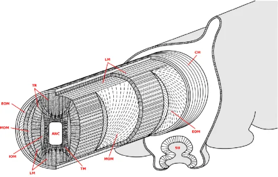
In this framework, it is easy to understand why several engineers are looking at nature as a very rich source of inspiration: most animals move and interact with the environment (manipulation, in its many forms) by appropriately combing soft tissues with rigid structures and/or stiffening mechanisms [2]. With particular reference to soft biological structures, a highly smart motion system exists which exploits geometries, arrangements and tissue properties in order to accomplish very complex deformations, tasks and consistent stiffening (still unequaled by the majority of modern robotic manipulators): the so-called ―muscular hydrostat‖, a muscular structure whose volume remains constant during deformation. This means that when its diameter decreases, its length increases and vice versa. This is obtained by a general arrangement in main longitudinal and transverse muscles, with variations in different animals [3]. Thanks to the combination of transverse and/or longitudinal muscle contractions, the muscular hydrostat can implement elongation, shortening, bending and stiffening (with antagonistic co-contractions) movements of selected parts of the arm. There are several animals that count partially or totally on a muscular hydrostat system for their limbs. Generally speaking, they have virtually infinite degrees of freedom, being able to bend in all directions at any point along their length. They are an excellent example of how a soft structure can increase its own stiffness and produce forces. Among others, we can recall tongues, human lips, squid tentacles, elephant trunks and octopus arms (see Figure 1).
There have been different attempts in literature to use this peculiar structure as inspiration for the development of robotic manipulators. One of the first works was conducted by Walker’s group [4], which implemented the basic concepts outlined by the studies of the octopus arm in the OCTARM platform. Although the robot was very successful, it cannot be considered a complete example of how the muscular hydrostat concept can be exploited. It only has longitudinal actuators that are able to shorten and bend the manipulator, but no active antagonistic elements are included and, as a consequence, no stiffness variation can be obtained.
Figure 1. The muscle arrangement within the octopus arm: the longitudinal muscles (LM) run along the arm, while the transverse muscles (TM) lay on the cross section and are connected to the external connective tissue by means of the trabeculae (TR); oblique muscles are arranged helicoidally and they are divided into external (EOM), medial (MOM) and internal (IOM) muscles; in the inner and outer sides of the arm, the axial nerve cord (ANC) and a thin layer of circumferential muscles (CM) are lodged, respectively. A sucker (SU) is also depicted in the bottom part.
Along the same conceptual line, the basic principles taken from the study of another cephalopod (the squid) have been applied to the development of a surgical tool which relies on a number of longitudinal cables that are able to bend the tool in any direction (by pulling the right cable) or to change its stiffness by compressing a central spring [5]. In this case, the antagonistic effect is obtained by including a passive component (a spring) which works against the cable forces along the same axis. In principle, this is able to change the stiffness of the structure, but is slightly different from what happens in the natural counterpart: in cephalopods, stiffness change is due to forces which lie in perpendicular planes but act antagonistically due to the isovolumetric constraint.
Another very recent work, which translates the bioinspired concept into the development of a surgical tool, is reported in [6]. In this case, also, the actuation system does not rely on the presence of all the main components of a muscular hydrostat, but its main capabilities are reproduced (namely bending, elongation and stiffening) without any rigid structures and with the use of flexible fluidic actuators and granular jamming chambers.
A robotic arm, which closely replicates the antagonistic mechanism of the octopus muscular hydrostat and resembles the particular arrangement of the natural contracting elements, is reported in [7]. In this case, longitudinal and transverse muscles have been singularly reproduced by using McKibben actuators and their selective activation reproduces movements very similar to the behavior of the octopus. Despite the effectiveness of the structure, in this case the presence of a rigid support (necessary for holding in place the different actuators) can introduce some limitations in motion capabilities (active and passive) and in interaction with the environment. The continuity of the
structure instead is a huge advantage because it allows the real octopus arm to deform and adapt to the environment at any point along the limb.
In order to overcome the need for rigid supporting structures, actuation technologies are required, capable of providing local force and deformation, yet without reducing the overall compliance of the structure permanently; in other words: an artificial muscle. SMA technology has already demonstrated that it is able to meet these requirements and for this reason has already been used in previous bioinspired soft robots. An SMA actuation mechanism is based on a material-specific thermo-mechanical effect, due to the solid state transformations induced in the microstructure of the alloy by temperature changes. In particular, during heating, the alloy changes its lattice from a martensitic phase (BCT crystallographic configuration) to an austenitic one (FCC).
The combination of flexible structures and SMA springs appears in the Omegabot [8]: a body made of a single composite part, which implements two four-bar mechanisms and a spherical six-bar mechanism, is coupled with eight SMA springs and anisotropic friction pads to replicate the crawling motion and steering of an inchworm. Inspired to a similar natural model, the GoQBot is based on two (functionally four) SMA springs coupled with an elastomeric material which resembles the body of a caterpillar [9] and is able to mimic its ballistic rolling movement. The coupling between SMA alloys and soft materials has been successfully experimented also underwater and, other than the already cited previous works on the octopus arm, a biomimetic robotic jellyfish (Robojelly) has been presented in [10]. It is based on the morphological features of a medusa to reproduce its propulsion mechanism by relying on SMA-based composite actuators (i.e., BISMAC actuators composed of silicone, spring steel and an SMA wire).
Recalling the main features which make the octopus arm an excellent source of inspiration, it is worth mentioning the total lack of rigid structures and the arrangement of its muscles: they are organized into transverse, longitudinal and obliquely oriented groups, as illustrated in Figure 1. The orthogonal arrangement of the longitudinal and transverse muscle groups is a key factor in implementing the antagonistic mechanism. For this reason, the transverse and longitudinal muscles are mainly responsible for elongation, shortening, bending and stiffening, while the oblique muscles are primarily devoted to twisting (neglected in this study).
The authors have already proposed a novel concept for the functional unit of a soft robotic manipulator based on the octopus arm morphology, which broadly relies on soft and flexible structures [11]. The present paper presents the integration of the functional units in an arm prototype, with further improvement in terms of flexibility (by completely removing any remaining hard parts) and of compactness (with the possibility to create a standalone arm which can be mounted on mobile platforms), as well as its experimental validation.
2. Design of the Soft Actuating Unit Inspired to the Muscular Hydrostat
Drawing inspiration from the Octopus vulgaris muscular hydrostat, the design of the arm is based on longitudinal and transverse actuation units. The units are obtained using SMA springs, both longitudinal and transverse, a longitudinal motor-driven cable, and a soft and flexible overall supporting structure obtained with a braided sleeve. No rigid structures were used and SMA springs and the motor-driven cable are the only actuators providing motion to the arm. It is worth mentioning
that the motor is located at the base of the arm, so it does not influence the softness and flexibility of the arm.
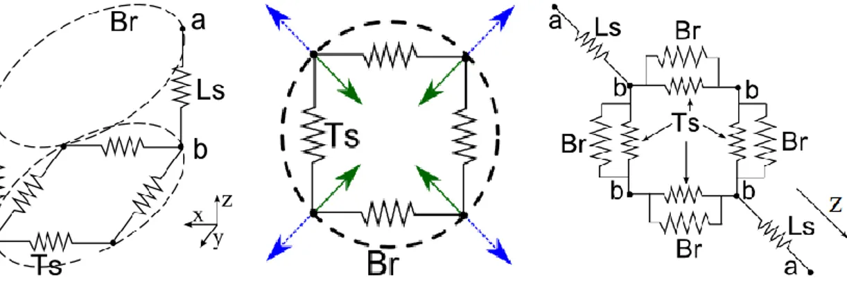
The supporting structure of the arm is based on a sleeve made of braided polyethylene threads (similar to those of the McKibben actuators). As illustrated in [12], the sleeve is highly flexible and, at the same time, has the double role of supporting the actuators and transmitting forces from transversal to longitudinal direction and vice-versa. The arm was designed by taking into account the interaction between the braided sleeve and the antagonistic system made of transverse and longitudinal springs (Figure 2a), since the main function of the braided sleeve is to transmit deformation smoothly from the local unit to the overall arm. The actuation system can be divided into many independent units, each composed of four transverse and two longitudinal SMA springs. The transverse actuators are arranged as shown in Figure 2b.
Figure 2. Schematic diagrams of the arrangement of the SMA springs composing a single unit inside the arm: (a) 3D representation; (b) transverse spring forces; (c) simplified planar representation of the complete system. Four transverse springs (Ts) are connected in parallel to four springs that represent the action of the braided structure (Br). Each couple of transverse springs is connected to a longitudinal one (Ls). Green arrows represent the direction of the net force generated by the transverse springs during actuation; blue dotted arrows represent the reaction force of the braided sleeve.
(a) (b) (c)
The net force produced by the transverse actuators is in radial direction, even if the springs are arranged in a square shape, due to the effect of the vectorial sum of the forces. The braided structure opposes a reaction force in the same direction of the net force of the springs. This force depends on the diameter of the braided sleeve and was measured experimentally. The experimental setup consisted of a system of four rods set normally to the external surface of the braided structure, in four equidistant points along the diameter, in order to simulate the action of the spring forces. A force was applied to the rods, which were previously constrained to the braided structure, until reaching 20% diameter reduction. The target of deformation was chosen on the basis of the performances observed in the octopus [13] and is one of the specifications for the design of the actuation system. The applied force was measured and used as parameter for the design of the SMA springs.
The single unit is considered as a planar structure; Figure 2c shows the simplified model of the relation between the actuators and the braided structure according to the following considerations:
(i) points b are the attachment points of the springs on the braided structure; they can move and maintain the square shape of the springs;
(ii) points b are the attachment points of the longitudinal springs on the braided structure; the distance between points a and b varies according to the relation between the diameter and the length of the unit (from [14] and readapted in [11]);
(iii) the initial length of the longitudinal springs depends on the length of the single unit;
(iv) the geometry of the braided structure is considered ideal and is not subjected to punctual deformations; thus the relation between diameter and length is purely geometrical;
(v) the forces are transmitted between the springs without loss from the radial direction to longitudinal direction.
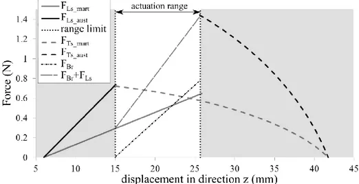
The design aims at maximizing the forces generated by the transverse springs, complying with the specification of a 20% diameter reduction. A linear elastic model was used to calculate the spring rate and the maximum force of a spring from its geometry (wire diameter, spring diameter and number of coils) and from the material characteristics in austenitic and martensitic phases [15]. An algorithm developed in MATLAB® allows the geometry of all the springs to be designed, by iteratively searching for the best spring geometry which maximizes diameter reduction and thus elongation. The algorithm consists of two main parts: first, the performance of the springs is calculated for all possible combinations of geometric parameters, for both transverse and longitudinal springs, then the equilibrium of the forces of the system, described in Figure 2c, is calculated for all the combinations found. The output of the algorithms is the geometry of the transverse and longitudinal springs, and the expected diameter contraction. In the iterative process, the best result is chosen among those which showed comparable performance with minimum power consumption (calculated from the resistivity of the wire and the total wire length). Figure 3 shows the plot of equilibrium of the forces in the direction of the longitudinal springs (z in Figure 2). The solid lines represent the longitudinal springs and dashed lines the transverse ones. The latter are not linear because spring elongation is determined by the geometrical characteristic of the braided sleeve which the springs are connected to. The two equilibrium points are highlighted by small circles and are calculated by taking into consideration the force that the braided sleeve applies on the system (Br in Figure 2): FBr + FLs = FTs. The force of the braided sleeve
(FBr in Figure 3) is null when it is in rest configuration (FLs_aust = FTs_mart), and increases linearly when
the braided sleeve is contracted radially. The transverse springs, when in austenitic phase, must balance the force of the longitudinal spring summed to the force of the braided sleeves (FBr + FLs_mart = FTs_aust).
This design choice led to another important consequence: the SMA springs are purposely designed to deform and shape the arm, but they are not responsible for generating the interaction forces. This is the main reason why the arm was also equipped with a motor-driven cable (providing less dexterity, but much more force).
This design procedure was repeated for each unit (defined by four transverse springs and two longitudinal springs), but starting from different diameter values. The octopus arm, in fact, is not cylindrical which has implications in several behaviors (as clarified in the next section). For this reason, a conical braided sleeve was used and, consequently, the single artificial muscular hydrostat units have different diameters. The number and the distance of the actuators were defined as described in Section 3.1. Arm elongation was determined by the geometrical properties of the braided sleeve,
since the specification was given only for the reduction of the diameter. Total elongation can be easily calculated for each section [12]. The longitudinal springs were designed with the constraint of having the same internal diameter and wire diameter, so that the only output parameter of the design process was the number of coils. Two rows of longitudinal springs are arranged on two opposite sides of the sleeve. The purpose was to combine more longitudinal springs (i.e., springs connected in series), to a final number of three on each side, thus reducing the wiring. The longitudinal springs were anchored to the braided sleeve between the transverse sections respecting the number of coils defined for each actuation unit.
Figure 3. Equilibrium of the forces in the direction of axis z (Figure 2). Black and grey solid lines: austenitic and martensitic force of longitudinal springs, respectively. Black and grey dashed lines: austenitic and martensitic force of transverse springs respectively. Dots and dashed line: force of the braided sleeve. Long dashed line: sum of the force of the braided sleeve and the longitudinal spring force in martensitic phase.
3. Prototype of the Complete Octopus-Like Robotic Arm
The development of the single units allowed the production of the complete octopus-like robotic arm. The total length of the structure from base to tip is 400 mm, and the diameter is 30 mm at the base and 14 mm at the tip. Several tasks can be accomplished by the arm as a result of the combination of simultaneous activations of the single springs. Specifically, it is possible to obtain elongation, shortening and local bending, which are the basic movements the octopus performs and combines to generate more complex actions, e.g., reaching [16]. Moreover, the presented prototype is equipped with a motor-driven cable that permits a simple but strong grasping capability on one plane.
The complete manipulator consists of the support sleeve, actuators, sensors, a cylindrical base from which the arm departs and a very thin silicone skin-like layer with passive silicone suckers. This skin covers the whole structure and components, insulating them from the water environment. Its thickness (less than 1 mm) is the result of the best compromise between mechanical robustness (essential for insulation) and the attempt to reduce mechanical interferences during arm movements. Regarding the cylindrical base, it houses a DC motor dedicated to actuating the cable (which is fastened at the tip, inside the arm) and gathering all the electrical wires from the arm. The entire system, therefore, is
self-contained and only three multipolar cables depart from the base, which are necessary for power supply and control signals.
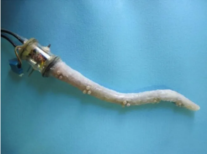
A detailed sketch describing all the components of the robotic arm is reported in Figure 4a and described in detail in the following sections, while a picture of the real prototype is shown in Figure 4b.
Figure 4. (a) General description of the octopus-like robotic arm: the ―shoulder‖ of the arm is composed of the cylindrical base (a1) that houses a DC motor (a2), and an external structure with a waterproof servomotor which can turn the base on the x axis (a3); in (b), a section with transverse (b1) and longitudinal (b2) SMAs are highlighted; in (c), the external skin with the passive suckers (c1) are shown; (b) The real prototype.
(a) (b)
3.1. The Actuation System
SMAs were chosen to drive the complex movements of the octopus robotic arm because of their lightness, their high energy-to-volume ratio and especially for their ability to be deformed in many different shapes without a substantial loss of actuation performances. The thermo-mechanical transformation occurring inside the alloy causes noticeable changes in the macroscopic structure, consisting in both shape changes and force generation that are exploited by the actuator. Maximum achievable deformation is usually about 8% of SMA wire length; this is the reason why, in order to achieve a larger resultant stroke, the material was shaped into coils, obtaining spring-like actuators that are able to produce more important displacements.
In the present work, as a result of the procedure described in Section 2, SMA helical-shaped wires (SmartFlex®, SAES Getters S.p.A.) with a 0.2 mm diameter were used to form springs with an external diameter of 1.4 mm and variable length ranging from 10–20 coils for the transverse springs and 30 coils for the longitudinal springs.
The SMA springs used on the octopus-like robotic arm are activated by sending current PWM signals, which provide the energy to heat up the alloy and, consequently, to move and actuate the entire arm. In this context, temperature is an essential parameter that needs to be taken into account: indeed, while the activation phase is actively controlled by the current inputs, the cooling phase is passive. For this reason, an appropriate environment needs to be taken into consideration to accelerate
the process and prepare the springs for the next activation. The heat transfer coefficient is the most influencing parameter: the best compromise has to be found, therefore, both for the heating and the cooling phenomena. In view of this, a combination of water and glycerol is an optimal combination [15]; however, since there are many electrical components inside the manipulator and red-ox phenomena during spring activation, this may not be a suitable solution. Instead, the use of mineral oil inside the whole arm (contained by the silicone skin) well fits the purpose, since exhibiting also non-conductive properties and an adequate chemical inertia (even after many working cycles).
An antagonistic action of longitudinal and transverse actuators is at the basis of the functional unit of the arm. As explained in Section 2, transverse actuators are positioned inside the arm orthogonally to the direction of the arm’s longitudinal axis, arranged in a square shape (Figure 5a). A single spring is linked to the sleeve in three points, while the extremities are linked together in the fourth corner of the square. Longitudinal actuators are positioned on the external surface of the arm and their extremities are linked to the braided sleeve (Figure 5b). The contraction of the transverse SMA springs reduces the diameter of the braided sleeve, but this effect does not propagate longitudinally very much. The distance between the transverse SMA units, therefore, was calculated and set in order to maintain a smooth radial contraction along the length of the arm (avoiding a visible ―barreling effect‖ [12]). The assessment of the suitable distribution automatically led to setting the number of transverse SMA units which, consequently, also affected the longitudinal SMA units.
Figure 5. Soft actuation for the octopus-like robotic arm: (a) the transverse SMA springs are housed inside the braided sleeve and connected to it; (b) the longitudinal springs are located outside the sleeve.
(a) (b)
Transverse actuators are distributed uniformly along the entire arm, at the maximum possible distance where uniform diameter reduction is maintained when two adjacent springs are actuated. A total of 11 springs are positioned along the arm, at a distance of 30 mm between one actuator and the other. One of the advantages of having SMA longitudinal actuators is that it is possible to perform a local bend in a desired portion of the arm without influencing the rest of it. The number of longitudinal actuators determines the possibility to independently bend the arm in multiple directions and defines the number of independent functional units that can be controlled. Having one functional unit for each transverse module would have increased dramatically the number of electrical cables and, consequently, arm stiffness. For this reason, a small number of longitudinal springs was used (six in
total) to provide multiple bending on the transverse plane. The position of the longitudinal actuators limits the bending movements in the transverse plane (xz). The cable driven by the DC motor (Solarbotics, GM22–gear ratio 298:1) acts in the yz plane and is used to perform arm retroflexion and powerful interaction with objects. A detailed description of the actuators arrangement can be found in Figure 6.
Figure 6. Schematic drawing that shows the arrangement of the transverse (T1–5) and longitudinal (L1–3, side a and side b) springs.
To further reduce stiffness due to the electrical cables, a small enameled copper wire with a diameter of 0.1 mm was chosen. As seen in Figure 5b, all the wires run in parallel with the threads of the braided sleeve, in order to reduce the impact on the overall flexibility and to avoid constraints on elongation. Since the number of wires inside the arm is considerable, they were reduced by connecting in electrical series some SMA springs, even if this entailed reducing the number of independent actuating units. The arm is provided with elongation capabilities thanks to five independent transverse actuators, whilst six longitudinal springs allow shortening and bending in three independent units. In addition to the ability of elongation, shortening, bending, grasping objects and their combination, the arm includes further orientation capabilities thanks to an underwater servomotor placed at the base of the cylindrical housing.
3.2. SMA Control Implementation
Control of SMA actuators was obtained by means of a hierarchical architecture which can be organized on three abstraction layers [17].
The lower level layer is structured in analogy to the neuromuscular interface of the real octopus. It consists of the power electronics driving board, designed to provide the thermo-mechanical actuators with the required amount of power for a correct, efficient and safe activation of the alloy. The board deploys 11 channels which can be used for controlling the SMA actuators in the arm. Each driving cell consists of an active component (power Darlington) operated in switching mode to obtain a PWM signal which regulates power delivery from the constant voltage source of the main power supply of the prototype. Each power channel has a Hall effect current sensor (automotive grade) that is connected in series with the corresponding SMA, thus providing a current measurement feedback to the superior level. Since the spring control strategy is based on an on–off activation, this feedback is fundamental in maintaining spring activation and, subsequently, in motion performances. This design choice was dictated by the SMA thermo-mechanical behavior: it is well known that these alloys have several control issues related to their intrinsic hysteresis, however, despite attempts by several research
groups, a suitable level of accuracy and reliability has not yet been achieved. For this reason, in the present work, every active spring has been powered to achieve full activation. Although this restricts the available functionality, the number of used springs allows a rich repertoire of combinations.
Instantaneous duty cycle determination is demanded of the middle level. This abstraction level was organized so as to resemble the peripheral nervous system of the animal [18]. Since this nervous system part is highly important in the biologic counterpart, the design assigned the majority of the robot’s computational requirements to this layer, which was implemented using a DSP based (Texas Instruments 32-bit TMS320F288) control board with a 10-bit resolution and 10-ksps sample frequency. The firmware consists of different modules:
- A lower module implements a simple PID controller on the output variable ―current on the SMA actuator‖ measured from the Hall sensors and sent to the core processing after analog to digital conversion. The decision to use electrical current instead of voltage activation as control variable makes it possible to use SMA springs independently of coil length. Current activation thresholds are roughly dependent only on wire material and diameter. The presence of this module in this layer partially breaks the abstract/logical separation between middle level and lower level as stated. This is an acceptable choice, however, which allows greater flexibility thanks to software implementation rather than the use of plain hardware electronic control. - A higher module generates the electrical current set-point profiles on the basis of input
parameters from the higher level which determines the tasks, targets and goals of the animal’s behavior [19]. The higher level was implemented with different Reservoir Computing algorithms [20,21]; however, this is not the subject of this work which focuses on the lower two levels and on the mechanical aspects of the arm itself.
From bottom to top of the control architecture shown in Figure 7, controlled variables are the current on the SMA and the current set-point profiles.
The typical movements of the real octopus arm are generated by sending preconceived inputs from the higher level (corresponding to the central nervous system) to execute a particular task, such as positioning of the tip of the arm or performing specific time-dependent movements, which resemble stereotyped movements of the real animal. Our tests on the octopus-like robotic arm were performed by eliciting the parameterized but predetermined responses from the middle layer (which implements the role of the biological peripheral nervous system) and by sending predetermined codes from a MATLAB runtime instance through a serial RS-232 to the MCU board. Depending on the combination of activated SMA springs, the whole structure responds with elongation (all the transverse springs), shortening (all the longitudinal springs) or bending (locally—single springs; globally—all the springs on the same side) movements. These are the basic movements of the arm and their characteristics will be analyzed in the remaining part of the paper.
It is worth highlighting that the combination of these basic gestures can potentially lead to a complex behavior of the whole arm, as in the case of the real octopus. The possible movements are listed below for completeness (although beyond the scope of this paper).
Figure 7. Hierarchal architecture with three abstraction layers.
Basic movements from the middle level mainly consist of: 1. Simple bending
2. Multiple bending 3. Elongation 4. Shortening
5. Stiffening: the arm tunes its stiffness thanks to different longitudinal and transverse SMAs activations
Complex stereotyped movements (derived from biological literature) are provided in the implementation: 1. Reaching-like movements [22]: the servomotor at the base orients the arm and the longitudinal
cable positions the arm upwards performing a retro-flexion. Then a stiffening wave is generated with a proximo-distal sequence of SMAs.
2. Fetching-like movements [23]: simultaneous activation of specific longitudinal and transverse actuators resulting in a stiffening of the proximal and the distal part of the arm (co-activation of transverse and longitudinal actuators) and bending of the central part of the arm.
4. Experimental Trials and Results
To quantify its active mechanical performances, the prototype was placed in a testing water tank and the bending angles and workspace were measured. Then, the smallest object that the manipulator could grasp was tested. Finally, isometric force trials were performed to measure the force exerted axially by the SMAs and by the cable.
4.1. Operating Limit Angles
The angles of operation and working space of the robot were assessed experimentally by placing the robot in a fixed position in the center of a testing tank. Arm movements during different actuation modes (by cable or by SMAs) and sequences of actuations were recorded with two orthogonally placed cameras for further photogrammetric processing.
In this case, the arm is virtually divided into three segments, corresponding to the three parts where an opposite couple of longitudinal SMA springs acts (see Figure 6: L1, L2 and L3 couples). This
makes it possible to measure the angles between the axis of the virtual segments; for this purpose, three different bending positions were chosen: simple bending of the entire arm and bending consisting of one and two convexity changes, respectively (see Figure 8). They are adequately complex to represent the bending capabilities of the arm and, at the same time, simple enough to be analyzed. A higher dexterity compared to simple cable actuation is reached using the longitudinal SMA actuators coupled with the soft structure. It is worth mentioning that the angles of operation described here do not represent the maximum contraction capabilities attributable to the SMA coils since a partial
limitation was imposed at power supply level to preserve the functionality and durability of the actuators.
Figure 8. Bending types and reference angles.
Several activation sequences were evaluated for each bending type, until the maximum angles were reached. These values also represent the maximum limit angles for operating the robot without any risk of damaging the SMAs and the sleeve.
The measured angles are reported in Table 1. Numerical data are referred to Figure 8. They represent the maximum angles that the robot is able to achieve during the specific bending type. Values refer to the mean of five trials regarding the described measurement procedure.
The results reported in Table 1 clearly show that the SMA springs reach a lower limit angle if coupled with the activation of other springs: in simple bending, the highest angle is achieved (column 1); when the second SMA spring is added, the first spring is able to reach only a lower level of contraction (column 2) and the worst performances (even if for a few degrees corresponding 10.5% and 2.5% of bending reduction to column 1 and 2, respectively) are shown when all the three springs are activated (column 3).
Table 1. Operating limit angles in different activation conditions.
Simple Bending [deg] Single Change of Convexity
Bending [deg]
Double Change of Convexity Bending [deg]
a0 85 a1 78 a2 76
b1 55 b2 44
One possible reason for this behavior can be found in the internal mechanical state of the arm itself during motion. The activation of a spring deforms the braided sleeve; the sleeve is the supporting structure of the arm and, due to its nature (which is also one of the main reasons why it was adopted), it propagates the deformation longitudinally and radially. Thus, when only one longitudinal SMA spring is activated it shows its best performance, but when it is activated in combination with other actuating elements its force has a lower effect since the mechanical coupling among the elements increases the internal stress state of the arm.
4.2. Workspace
The workspace was assessed by analyzing several video frames of the arm performing its maximum capabilities of free motion (without obstacles) which also allowed the identification of workspace boundaries. The shaded area reported in Figure 9 represents the cloud of points which can be reached by the arm tip in the horizontal plane thanks to the SMA springs activation (a) and the trajectory which is followed by the arm tip in the vertical plane when the motor-driven cable is used (b). The workspace is the combination of the two working areas which were experimentally evaluated: A = 400 mm, B = 440 mm, C = 290 mm and D = 150 mm.
Figure 9. Graphical description of the workspace limits on xz (a) and yz (b) plane.
(a) (b)
4.3. Grasping Capabilities
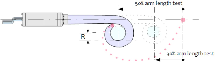
Measurement of the minimum radius (as shown in Figure 10) of an object which can be effectively grasped by the soft actuation mechanism was experimentally assessed by performing a set of trials with objects of different diameters. When the arm was in resting position and completely submerged, the object was positioned at 150 mm from the z axis and at a variable distance from the tip (specified in Table 2). In each trial, grasping was tested five times and only using cable driven actuation. Effectiveness of the operation was finally checked visually.
Figure 10. Minimum grasping radius definition diagram.
Trials were conducted using three cylinders which have radii equal to: 12.5 mm, 17.5 mm, and 22.5 mm. Grasping the object at 50% of the length of the arm is effective for radii greater or equal to 17.5 mm. In trials in which the object was positioned at 30% from the arm tip, the minimum radius was decreased and the robot demonstrated to be able to grasp effectively the 12.5 mm cylinder too (Table 2).
Table 2. Grasping ability in function of object radius and distance from the tip.
Testing Radii [mm] Grasping Effectiveness,
50% Distance from the Tip
Grasping Effectiveness, 30% Distance from the Tip
12.5 Fail Pass
17.5 Pass Pass
22.5 Pass Pass
Grasping effectiveness strongly depends on the point where the object is grabbed, which is in accordance with the expected results. The conical shape of the sleeve, rather than a cylindrical shape, creates a non-constant curvature arc (a spiral-like shape) during bending, allowing the arm to grasp objects of different sizes. In other words, this means that the possibility to handle different objects depends on the morphology of the structure rather than on actuator regulation. Using a conical arm structure (instead of a cylindrical structure) makes it possible for the arm to grasp objects of different sizes depending on the distance from the tip due to the spiral shape the arm forms when actuated.
Manipulation trials were successfully carried out (i.e., the object was correctly grasped and towed without slipping out of place) on the following objects (Weights are listed only as reference and are not the effective transported weights because buoyancy of the object and possible interactions against the tank bottom may be non-negligible.), also shown in Figure 11:
- Object 1: rectangular cross-section wooden bar, 25 mm × 30 mm, 75 g weight. - Object 2: round polymeric cylinder, 25 mm outer diameter, 58 g weight. - Object 3: round polymeric tube, 25 mm outer diameter, 250 g weight. - Object 4: round aluminum tube, outer diameter 60 mm, 478 g weight.
Figure 11. Grasping of different objects (from top left): wooden bar (object 1), thin polymeric tube (object 2), thick polymeric tube (object 3) and aluminum tube (object 4).
4.4. Force Measurements
The forces generated by the soft arm were measured with an ad hoc set-up, purposely realized to measure the forces which are exerted by its biological counterpart (the real octopus) [13]. The cylindrical base of the arm was fastened in a fixed position in the testing tank. The tip of the arm was mechanically secured to an inelastic cord connected to a digital dynamometer. The set-up was mounted and blocked on the side of the tank and then the measuring instrument was zeroed.
Peaks of axial isometric forces were reached: 1.2 N using SMA springs and 10.8 N using longitudinal cables. As expected, the force produced using the cable was much higher than the spring capability. The choice of the helical shape is a trade-off between the stroke within the available space (without achieving prohibitive values in terms of power consumption) and the produced force (see [24] for other details on the mechanical performances of SMA associated with geometrical choices). The resulting forces applied to the environment are thus limited, but in line with the model proposed in Section 2. Moreover, as explained in the design section, the main objective was to achieve octopus-like performances in terms of deformation and motion capabilities, not in terms of the interaction forces generated. By combining small SMA springs for local activations (providing high dexterity and capability to reach hardly accessible spaces) and a motor-driven cable for global motions and powerful actions (such as grasping), the arm is able to cover a wide spectrum of applications.
5. Conclusions
The morphology and structural arrangement of an octopus arm is a very fascinating and concrete example of how a soft arm can effectively interact with the environment. The octopus arm can produce several dexterous movements thanks to its softness, but also produce relatively high forces thanks to its capability to vary its stiffness. In this work, we have reported the final stage of development and testing of an octopus-like robotic arm, broadly based on the main structure of the octopus arm (the muscular hydrostat) and capable of performing the same basic movements. The previous model
purposely developed to design the artificial muscular hydrostat was improved to take into consideration all the system components leading to new specifications for the robotic arm. Results on reachable workspace, grasping capabilities and produced force have been reported and discussed demonstrating that SMA springs arranged so as to resemble the octopus morphology can be effectively used to enable fine octopus-like movements, while a motor-driven cable can confer the necessary force to produce powerful grasping. Moreover, in this last version of the manipulator, we demonstrated that it is possible to realize a self-contained octopus-like robotic arm without any rigid part, highly adaptable and suitable to be mounted to any underwater vehicle. Thanks to its softness, it is able to deal with all types of objects with very low risks of damage or limited safety issues; at the same time, it can produce relatively high forces when necessary. Finally, the handling capabilities of the arm were tested showing how different sizes can be addressed through the structure’s morphology design rather than through accurate activation of the actuators.
Acknowledgments
This work was supported by the European Commission in the ICT-FET OCTOPUS Integrating Project, under contract n. 231608.
Author Contributions
Matteo Cianchetti was responsible of the conception and the overall design of the structure; Maurizio Follador developed the theoretical model describing the antagonistic behavior of the springs; Alessia Licofonte realized the SMA springs and assembled the mechanical hardware; Francesco Rogai designed the electronics and the control schemes; Matteo Cianchetti, Alessia Licofonte e Francesco Rogai conducted the experimental trials and analyzed and interpreted the data; Cecilia Laschi supervised the study and provided scientific steering; all the authors contributed to the manuscript writing, review and revision.
Conflicts of Interest
The authors declare no conflicts of interest. References
1. Laschi, C.; Cianchetti, M. Soft Robotics: New perspectives for robot bodyware and control. Front. Bioeng. Biotechnol. 2013, doi:10.3389/fbioe.2014.00003.
2. Kim, S.; Laschi, C.; Trimmer, B. Soft robotics: A bioinspired evolution in robotics. Trends Biotechnol. 2013, 31, 287–294.
3. Kier, W.M.; Smith, K.K. Tongues, tentacles and trunks: The biomechanics of movement in muscular-hydrostats. Zoologi. J. Linnean Soc. 1985, 83, 307–324.
4. Grissom, M.D.; Chitrakaran, V.; Dienno, D.; Csencits, M.; Pritts, M.; Jones, B.; McMahan, W.; Dawson, D.; Rahn, C.; Walker, I. Design and experimental testing of the OctArm soft robot manipulator. Proc. SPIE 2006, 6230, 62301F.
5. Breedveld, P.; Sheltes, J.S.; Blom, E.M.; Verheij, J.E.I. A new, easily miniaturized steerable endoscope. Eng. Med. Biol. Mag. 2005, 24, 40–47.
6. Cianchetti, M.; Ranzani, T.; Gerboni, G.; de Falco, I.; Laschi, C.; Menciassi, A. STIFF-FLOP Surgical Manipulator: Mechanical design and experimental characterization of the single module. In Proceedings of the IEEE on Intelligent and Robotic Systems—IROS, Tokyo, Japan, 2013; pp. 3567–3581.
7. Guglielmino, E.; Tsagarakis, N.; Caldwell, D.G. An octopus anatomy-inspired robotic arm. In Proceedings of the IEEE/RSJ International Conference on Intelligent Robots and Systems (IROS), Taipei, Taiwan, 18–22 October 2010; pp. 3091–3096.
8. Koh, J.-S.; Cho, K.-J. Omega-Shaped Inchworm-Inspired Crawling Robot With Large-Index-and-Pitch (LIP) SMA Spring Actuators. IEEE/ASME Trans. Mechatron. 2013, 18, 419–429.
9. Lin, H.-T.; Leisk, G.G.; Trimmer, B. GoQBot: A caterpillar-inspired soft-bodied rolling robot. Bioinspir. Biomim. 2011, 6, 026007.
10. Villanueva, A.; Smith, C.; Priya, S. A biomimetic robotic jellyfish (Robojelly) actuated by shape memory alloy composite actuators. Bioinspir. Biomim. 2011, 6, 036004.
11. Laschi, C.; Mazzolai, B.; Cianchetti, M.; Margheri, L.; Follador, M.; Dario, P. A Soft Robot Arm Inspired by the Octopus. Adv. Robot. 2012, 26, 709–727.
12. Follador, M.; Cianchetti, M.; Laschi, C. Development of the functional unit of a completely soft octopus-like robotic arm. In Proceeding of the IEEE International Conference on Biomedical Robotics and Biomechatronics, Roma, Italy, 24–27 June2012; pp. 640–645.
13. Margheri, L.; Laschi, C.; Mazzolai, B. Soft robotic arm inspired by the octopus: I. From biological functions to artificial requirements. Bioinspir. Biomim. 2012, 7, 025004.
14. Caldwell, D.G.; Medrano-Cerda, G.A.; Goodwin, M. Control of pneumatic muscle actuators. IEEE Control Syst. 1995, 15, 40–48.
15. Follador, M.; Cianchetti, M.; Arienti, A.; Laschi, C. A general method for the design and fabrication of shape memory alloy active spring actuators. Smart Mater. Struct. 2012, 21, 115029. 16. Cianchetti, M.; Follador, M.; Mazzolai, B.; Dario, P.; Laschi, C. Design and development of a soft
robotic octopus arm exploiting embodied intelligence. In Proceeding of the IEEE International Conference on Robotics and Automation (ICRA), St. Paul, MN, USA, 14-18 May 2012; pp. 5271–5276.
17. Li, T.; Nakajima, K.; Kuba, M.J.; Gutnick, T.; Hochner, B.; Pfeifer, R. From the octopus to soft robots control: an octopus inspired behavior control architecture for soft robots. Vie et Milieu/Life Environ. 2012, 61, 211–217.
18. Zullo, L.; Fossati, S.M.; Benfenati, F. Transmission of sensory responses in the peripheral nervous system of the arm of Octopus vulgaris. Vie et Milieu/Life Environ. 2012, 61, 197–201. 19. Hochner, B.; Zullo, L.; Subre, G. The control of goal directed movements in the flexible arm of
the octopus. J. Mol. Neurosci. 2009, 39, S1–S132.
20. Kuwabara, J.; Nakajima, K.; Kang, R.; Branson, D.T.; Guglielmino, E.; Caldwell, D.G.; Pfeifer, R. Timing-Based Control via Echo State Network for Soft Robotic Arm. In Proceedings of the IEEE-INNS International Joint Conference on Neural Networks, Brisbane, Australia, 10–15 June 2012.
21. Li, T.; Nakajima, K.; Cianchetti, M.; Laschi, C.; Pfeifer, R. Behavior Switching by Using Reservoir Computing for a Soft Robotic Arm. In Proceedings of the IEEE International Conference on Robotics and Automation, St. Paul, MN, USA, 14–18 May 2012.
22. Yekutieli, Y.; Sagiv-zohar, R.; Aharonov, R.; Engel, Y.; Hochner, B.; Flash, T. Dynamic model of Octopus Arm. I. Biomechanics of Octopus Reaching Movement. J. Neurophysiol. 2005, 94, 1443–1458.
23. Sumbre, G.; Fiorito, G.; Flash, T.; Hochner, B. Octopuses Use a Human-like Strategy to Control Precise Point-to-Point Arm Movements. Curr. Biol. 2006, 16, 767–772.
24. Pons, J.L. Emerging Actuator Technologies: A Micromechatronic Approach; John Wiley & Sons: Chichester, UK, 2005; pp. 101–144.
© 2014 by the authors; licensee MDPI, Basel, Switzerland. This article is an open access article distributed under the terms and conditions of the Creative Commons Attribution license (http://creativecommons.org/licenses/by/3.0/).