SCUOLA DOTTORALE IN INGEGNERIA
SEZIONE SCIENZE DELL'INGEGNERIA CIVILE
CICLO DEL CORSO DI DOTTORATO
XXVIExperimental and theoretical investigation on road pavements
and materials through ground-penetrating radar
Dottorando:
Fabio Tosti
Docente Guida:
Prof. dott. ing. Andrea Benedetto
Coordinatore:
Collana delle tesi di Dottorato di Ricerca In Scienze dell’Ingegneria Civile
Università degli Studi Roma Tre Tesi n° 48
Sommario
L’utilizzo delle tecnologie non-distruttive (NDT) nel settore dell’ingegneria delle infrastrutture viarie è in continua e progressiva ascesa, e la necessità di sviluppare ed adottare nuovi standard di misurazione, basati sulla conoscenza approfondita degli strumenti di indagine e dei materiali costruttivi, per la verifica ed il monitoraggio avanzati dello stato di degrado e delle caratteristiche prestazionali delle pavimentazioni, sta sempre più emergendo. Una serie di fattori di varia natura ha contribuito alla crescita della domanda in questo ambito. Principalmente, il progresso tecnologico, sia hardware che software, degli strumenti di misura, l’intrinseca bassa rappresentatività e l’elevata intrusività delle tradizionali tecniche di controllo e monitoraggio, e gli effetti dell’attuale crisi economica che colpisce oramai da più di un lustro le economie di tutto il globo, hanno orientato ricercatori, professionisti, ed utilizzatori in genere, ad un impiego più diffuso ed efficace di tecnologie non-distruttive, stimolando anche l’interesse di governi ed enti locali per la notevole capacità di raccogliere un numero elevato di informazioni in tempi relativamente molto brevi.
In questo quadro generale, il ground-penetrating radar (GPR) o georadar può ragionevolmente essere ritenuto come la tecnologia non-distruttiva con maggiori potenzialità di utilizzo in molti settori scientifici e campi di applicazione, particolarmente in quello stradale, in virtù della sua elevata capacità di rilevare e, in parte, quantificare l’assetto della struttura profonda di una pavimentazione.
La maggior parte delle applicazioni radar in ambito stradale riguarda la stima degli spessori degli strati di pavimentazione e, più in generale, la valutazione delle sue caratteristiche geometriche profonde, che necessita in ogni caso del supporto di carotaggi per la calibrazione del sistema. Minor rilevo è stato invece dato negli anni alla possibilità di indagare le cause di degrado e le caratteristiche prestazionali di un’infrastruttura, in un’ottica di ottimizzazione delle strategie di nuova realizzazione, manutenzione e ripristino.
Il presente studio si pone come obiettivo principale quello di migliorare gli attuali processi di gestione e manutenzione delle pavimentazioni stradali, per prevenire fenomeni di ammaloramento e danno strutturale, anche ai fini del controllo della sicurezza di esercizio.
Più specificamente, sono state indagate quelle caratteristiche fisico-meccaniche critiche per lo sviluppo di situazioni di degrado nella pavimentazione. Per ognuna di queste grandezze sono stati calibrati dei modelli sperimentali alla scala di laboratorio, a cui è seguita una fase di validazione su scala reale per la definizione dei modelli finali. Inoltre, è stata analizzata l’efficacia di alcuni sistemi radar convenzionali e non, differenti per caratteristiche elettroniche e configurazione di indagine, e di varie tecniche di analisi del segnale.
Nel Capitolo 1 viene introdotto il problema relativo al monitoraggio delle pavimentazioni e dei materiali stradali, attraverso uno stato dell’arte sulle tecnologie non-distruttive e sull’impiego del GPR, con un dettaglio maggiore per utilizzi nel campo stradale.
Nel Capitolo 2 vengono trattati i princìpi della teoria elettromagnetica, su cui si fonda il funzionamento del radar. Con particolare attenzione vengono poi illustrati i fondamenti della teoria dello scattering alla Rayleigh, su cui si basa parte del presente studio.
Nel Capitolo 3 vengono esposti i risultati di un’indagine sperimentale per la stima del campo spaziale di umidità in un sottofondo. L’analisi ha previsto l’utilizzo di un sistema radar a trascinamento con antenne accoppiate a terra, avente frequenze centrali di indagine pari a 600 MHz e 1600 MHz. Sono state impiegate due tecniche di analisi del segnale: il metodo della riflettività superficiale è stato utilizzato per la stima del contenuto volumetrico di acqua nel sottosuolo attraverso la valutazione della permittività dielettrica relativa del mezzo indagato, e a sua volta implementata in un modello petrofisico di natura empirica; i valori dedotti sono stati quindi confrontati con le misure di umidità derivate localmente mediante sonde capacitive. L’applicazione del metodo di Rayleigh ha previsto invece la ricostruzione della struttura spaziale del campo di umidità nel dominio delle frequenze, confrontata dunque con quella valutata nel dominio del tempo attraverso il metodo della riflettività superficiale. I risultati hanno dimostrato come il GPR possa essere utilizzato efficacemente anche per misure di piccola scala (area di indagine ≤ 0.01 m2), e come la tecnica dello scattering alla Rayleigh si riveli efficace
per la stima del campo di umidità, senza bisogno di prelievi distruttivi per la calibrazione, o di leggi petrofisiche che richiedano la conoscenza del tipo di terreno da indagare.
Il Capitolo 4 è stato a sua volta dedicato alla indagine di un’ulteriore caratteristica fisica preminente per lo sviluppo di situazioni di degrado
strutturale negli strati portanti della pavimentazione, ovvero il contenuto di argilla. Analogamente all’approccio seguito per la stima dell’umidità, diversi strumenti radar e tecniche di analisi del segnale sono state tra di loro confrontate. La fase di sperimentazione in laboratorio ha previsto l’utilizzo di tre tipologie di materiale sciolto tipicamente utilizzato per la realizzazione degli strati profondi di pavimentazione. Tali materiali, classificabili all’interno dei gruppi A1, A2, e A3 della classifica AASHTO, sono stati progressivamente inquinati con crescenti percentuali di argilla comprese tra il 2% e il 25%, permettendo di studiare il fenomeno in un campo sufficientemente ampio. Due modelli di previsione sono stati sviluppati utilizzando informazioni nel dominio delle frequenze, ottenute attraverso la tecnica dello scattering alla Rayleigh, e informazioni sulla misura della permittività dei campioni di suolo attraverso l’uso di un sistema radar stepped frequency continuous-wave (SFCW) e di tecniche di analisi basate sull’inversione dei dati misurati nel dominio delle frequenze. I risultati hanno permesso di ottenere utili indicazioni sul tipo di tecnica di analisi e sulla tipologia di sistema radar più idonei da utilizzare in funzione della natura del terreno da studiare e dei quantitativi di argilla attesi. Nel Capitolo 5 viene descritta la possibilità di derivare informazioni sulle caratteristiche di resistenza e deformazione di una pavimentazione stradale a partire dalle proprietà dielettriche. In particolare, vengono presentati due studi volti ad indagare il fenomeno sugli strati non legati e sui terreni di sottofondo, e sugli strati legati in conglomerato bituminoso. Entrambi i modelli di previsione si sono rivelati validi, restituendo valori di modulo elastico delle strutture indagate di buona approssimazione rispetto al dato misurato con strumentazione light falling weight deflectometer (LFWD). Il Capitolo 6 contiene le conclusioni del lavoro e le raccomandazioni generali emerse dall’analisi dei risultati ottenuti.
Nell’Appendice A, sono descritti gli strumenti radar utilizzati per le attività svolte nell’ambito del Dottorato di Ricerca.
Abstract
Ground-penetrating radar (GPR) is being increasingly used over the last years in a wide range of applications, due to its flexibility and high potential to provide characterization and imaging of structures and materials. Overall, several reasons are contributing to increase the demand for the use of this tool and non-destructive testing techniques (NDTs) in general. Amongst all, it is worth citing technological advances of both hardware and software elements, an intrinsic lower significance of measurements provided by traditional monitoring techniques along with their greater invasiveness in measuring processes and, last but not least, the impacts of Global Economic Crisis on the use of economic resources affecting for years countries worldwide. The combination of such factors has led the interest of several skill profiles spanning from researchers, practitioners and end-users in general, and focused the attention of governments and local authorities on the high capabilities to gather a large amount of information in a relatively short time of surveying.
In the field of pavement engineering, GPR has been used since the early 1980s mostly focusing on the geometrical characterization of road structure, by evaluating layer thicknesses. Minor care has been given to the analysis of the main causes of damage and performance properties of pavements, in order to improve management of infrastructural asset through effective and efficient maintenance and rehabilitation actions, as well as to provide best conditions in design of new roads.
In that regard, this thesis is aimed to give a useful contribution also in the perspective of road safety issues by improving current processes of management and maintenance of road asset, along with the design of new roads, and provide effective support for the application and practical use of the tools described. Efforts have been spent in order to detect and quantify those physical and strength characteristics of road materials and subgrade soils that are relevant causes of damage, such that an effective planning of supporting actions for maintenance, rehabilitation and design of new roads may be timely performed.
Three main topics are addressed, namely: i) the evaluation of moisture spatial field in subgrade soils through a self-consistent frequency-based technique and the analysis of radar support scale in small-scale
measurements of water content; ii) the potential to detect and quantify clay content in load-bearing layers and subgrade soils through different GPR tools and signal processing techniques, and iii) the possibility to infer strength and deformation characteristics of both bound, unbound pavement structures, and subgrade soils from their electric properties.
The results are encouraging for applications in the field of pavement engineering.
Contents
LIST OF FIGURES ... XII LIST OF TABLES ... XVI LIST OF SYMBOLS ...XVII LIST OF ACRONYMS AND ABBREVIATIONS...XXII
1. INTRODUCTION ... 1
1.1BACKGROUND ... 1
1.2AN OVERVIEW OF NON-DESTRUCTIVE METHODS ... 2
1.2.1 Acoustic methods ... 3
1.2.3 Optical methods ... 4
1.2.4 Electromagnetic methods ... 4
1.2.5 Other methods ... 4
1.3GROUND-PENETRATING RADAR: STATE OF THE ART ... 5
1.3.1 Main road applications ... 6
1.3.2 Ground-penetrating radar systems ... 9
1.3.3 Ground-penetrating radar antennas... 11
1.4STATEMENT OF THE PROBLEM ... 13
1.5THESIS OBJECTIVES ... 14
1.6THESIS OUTLINE ... 15
2. ELECTROMAGNETIC FUNDAMENTALS ... 17
2.1GPR PRINCIPLES ... 17
2.1.1 Generation of EM waves ... 17
2.1.2 Propagation of EM waves in dielectrics ... 20
2.1.3 Main theories of scattering ... 23
3. VOLUMETRIC WATER CONTENT EVALUATION IN PAVEMENT ... 28
3.1INTRODUCTION... 28
3.1.1 Moisture content evaluation in subgrade soils ... 28
3.1.2 Moisture content evaluation in concrete pavement structure ... 35
3.2METHODOLOGY AND OBJECTIVE ... 39
3.3THEORETICAL BACKGROUND ... 39
3.3.1 The surface reflectivity method ... 39
3.3.2 The Rayleigh scattering method ... 41
3.4EXPERIMENTAL FRAMEWORK ... 43
3.4.1 Tools and equipment... 43
3.4.2 Study site, weather conditions, and soil properties ... 44
3.5RESULTS AND DISCUSSION ... 46
3.5.1 Punctual comparison of moisture data ... 46
3.6CONCLUSION ... 51
4. CLAY CONTENT EVALUATION IN PAVEMENT ... 53
4.1INTRODUCTION... 53
4.2METHODOLOGY AND OBJECTIVE ... 55
4.3THEORETICAL BACKGROUND ... 55
4.3.1 Rayleigh scattering technique ... 55
4.3.2 Full-waveform inversion technique ... 56
4.3.3 Time-domain signal picking ... 58
4.4EXPERIMENTAL FRAMEWORK ... 58
4.4.1 Experimental design ... 58
4.4.2 Test devices and equipment ... 59
4.4.3 Materials and laboratory testing ... 60
4.5RESULTS AND DISCUSSION ... 61
4.5.1 Clay content estimation–Rayleigh scattering method ... 61
4.5.2 Clay content estimation from the full-waveform inversion and the time-domain signal picking techniques... 67
4.6CONCLUSION ... 73
5. DETERMINING MECHANICAL PROPERTIES OF PAVEMENT FROM ELECTRIC PARAMETERS ... 75
5.1UNBOUND PAVEMENT STRUCTURES AND SUBGRADE SOILS ... 75
5.1.1 Introduction ... 75
5.1.2 Objective ... 76
5.1.3 Test devices ... 76
5.1.4 Experimental framework ... 77
5.1.5 Theoretical background and semi-empirical model ... 80
5.1.6 Results and discussion ... 83
5.1.7 Conclusion ... 86
5.2BOUND PAVEMENT STRUCTURES ... 87
5.2.1 Introduction ... 87
5.2.2 Objective ... 88
5.2.3 Experimental framework ... 88
5.2.4 Prediction model ... 90
5.2.5 Results and discussion ... 91
5.2.6 Conclusion ... 94
6. CONCLUSIONS AND RECOMMENDATIONS... 96
6.1CONCLUSIONS ... 96
6.2RECOMMENDATIONS ... 100
BIBLIOGRAPHY ... 102
APPENDIX A ... 122
A.1PULSED RADAR SYSTEMS ... 122
A.1.2 Air-coupled antennas ... 126
A.2SFCW RADAR SYSTEMS ... 127
A.2.1 Vector network analyser HP 8573C–Hewlett Packard Company, USA .... 127
ABOUT THE AUTHOR ... 129
INTERNATIONAL JOURNAL PUBLICATIONS... 129
Accepted for publication... 130
CONFERENCE PUBLICATIONS ... 130
Accepted for publication... 133
BOOK PUBLICATIONS ... 133
NATIONAL JOURNAL PUBLICATIONS ... 134
List of Figures
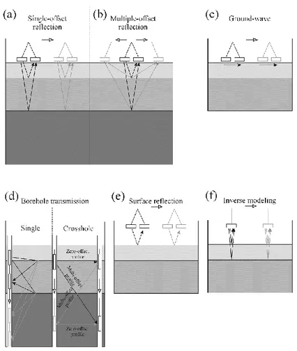
3.1 Sketch of GPR inspection techniques for moisture
evaluation through permittivity measurement: (a) single-offset reflection method; (b) multi-single-offset reflection method; (c) ground-wave method; (d) single- and cross- borehole transmission measurement; (e) surface reflection method;
(f) inverse modelling. 30
3.2 Capacitance probe WaterScout SM100, manufactured by
Spectrum Technologies, Inc., USA. 44
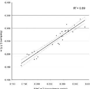
3.3 Site-specific calibration curve for capacitance probes
relating gravimetric (w) and volumetric water content (θ). 44
3.4 Study site for the GPR acquisition carried out over a 16 m×16 m area, 1 m spacing between the tracks (17×17 lines
square grid pattern). 45
3.5 Bar graphs representing GPR-derived (θGPR) and
probe-measured (θprobe) soil moisture contents on the 8 probe
sensing stations. 47
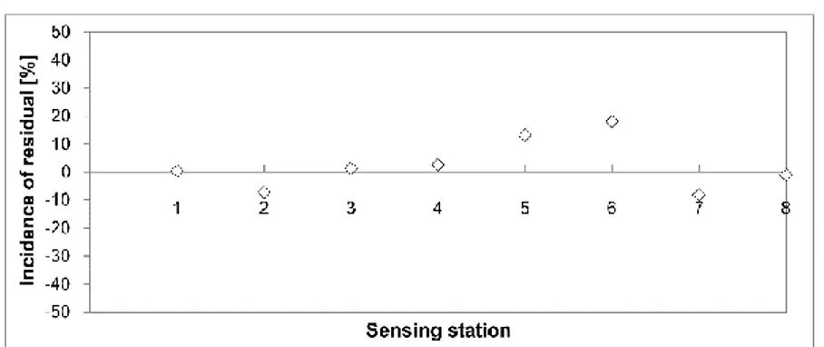
3.6 Incidence of moisture residuals on the 8 probe sensing
stations. 47
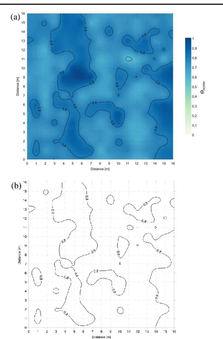
3.7 GPR-derived maps from the surface reflectivity method:
(a) normalized shallow soil dielectric moisture (θNORM)
map overlaid with iso-contour lines; (b) iso-contour lines
of the normalized shallow soil dielectric moisture (θNORM)
map. 48
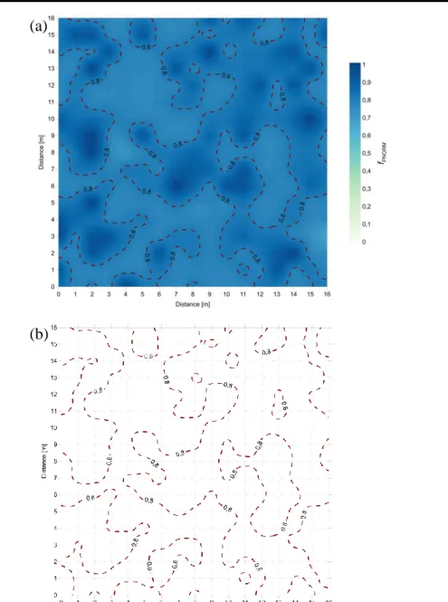
3.8 GPR-derived frequency peaks map from the Rayleigh
scattering method: (a) normalized frequency peaks (fPNORM) map overlaid with contour lines; (b)
iso-contour lines of the normalized frequency peaks (fPNORM)
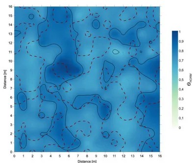
3.9 Normalized shallow soil dielectric moisture map overlaid with iso-contour lines from the “surface reflectivity” (solid black lines) and the “Rayleigh scattering” method (dashed red lines).
51
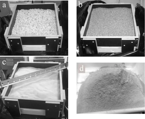
4.1 Typical road materials used for the tests: (a) A1 gravel; (b)
A2 coarse sand; (c) A3 fine sand; (d) bentonite clay. 60
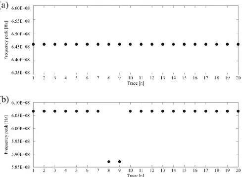
4.2 Measured frequency peak values extracted from the GPR
signal spectra of each tested soil sample: (a) stable domain values, soil sample 21 (A3, 4% clay); (b) unstable domain
values, soil sample15 (A2, 10% clay). 63
4.3 Modulation of the normalized frequency spectra with the
change of clay content for A1 (a), A2 (b), and A3 (c) soil
samples. 64
4.4 Trend of values of frequency spectra peak (fP) for
increasing rates of clay content. 65
4.5 Measured and modeled Green’s functions in the frequency
domain (amplitude | Gxx↑ | and phase ∠Gxx↑ ) domain: (a) soil
sample 13 (A2, 6% clay); (b) soil sample 20 (A3, 2% clay). 69
4.6 Measured and modeled Green’s functions in the time gxx↑
domain: (a) soil sample 5 (A1, 8% clay); (b) soil sample
17 (A2, 20% clay). 71
4.7 Correlation between clay content observed and predicted
by fitting the permittivity estimates from the full-waveform inversion and the time-domain signal picking technique (A1, A2, and A3 soil type).
73
5.1 Set-up of laboratory measurements carried out using the
5.2 In-situ measurements at Roma Urbe Airport: (a) trajectory of overrunning; (b) RIS 2k-MF Multi Frequency Array Radar-System; (c) light falling weight deflectometer Prima
100. 79
5.3 Correlation between bulk density (ρbulk) and relative
dielectric permittivity (εr), of the surveyed soil samples. 84
5.4 Correlation between the α parameter and the measured
relative dielectric permittivity (εr) of the surveyed soil
samples. 84
5.5 Comparison between observed (EOBS) and predicted
(EPRED) values of elastic modulus. 85
5.6 Incidence of residuals. 85
5.7 Test site for data acquisition carried out over a 4m×30m
square regular grid mesh of 836 nodes. 89
5.8 Normalized amplitude maps extracted from the 3-D matrix
and used for the calibration of the prediction model: (a) z1
= 0.000 m; (b) z2 = 0.084 m; (c) z3 = 0.138 m; (d) z4
= 0.188 m. 92
5.9 Comparison between observed (EOBS) and predicted
(EPRED) elastic moduli for the validation of the model. 93
5.10 Observed elastic modulus (EOBS) map from LFWD
measurements. 94
5.11 Predicted elastic modulus (EPRED) map from the calibrated
prediction model.
94
A.1 RIS 99-MF Multi Frequency Array Radar-System,
A2 RIS 2k-MF Multi Frequency Array Radar-System,
manufactured by IDS Ingegneria dei Sistemi S.p.A., Italy. 123
A3 PulseEKKO PRO 500, manufactured by Sensors &
Software Inc., Canada. 124
A4 Figure A.4: RIS Hi Bright, manufactured by IDS
Ingegneria dei Sistemi S.p.A., Italy. 125
A5 GPR survey van mounting the air-launched antenna RIS
Hi-Pave HR1 1000, manufactured by IDS Ingegneria dei
Sistemi S.p.A., Italy. 126
A6 SFCW radar set-up using a vector network analyzer HP
8573C (manufactured by Hewlett Packard Company, USA) and a linear polarized double-ridged broadband TEM horn BBHA 9120 A (manufactured by Schwarzbeck
List of Tables
3.1 Parameter values of the model from Equation (3.3.10) for
five different types of soil [Benedetto, 2010]. 43
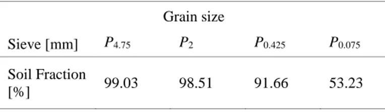
3.2 Grain size distribution of a relevant soil sample collected
within the test site area. 45
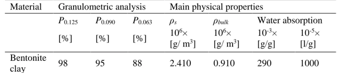
4.1 Main physical properties, grade, and classification of the
bentonite clay used for the experiments. 61
4.2 Main physical properties, particle size references, and
AASHTO classifications of the surveyed soil samples. 62
4.3 Measured values of the peaks of frequency spectra fP
[Hz×108]. 65
4.4 Values of the regression coefficients in Equation (4.3.1). 66
4.5 Values of relative dielectric permittivity (εr) from laboratory
measurements using the full-waveform inversion and the
time-domain signal picking techniques. 68
4.6 Values of the regression coefficients in Equation (4.5.8) and the root-mean-square errors (RMSEs) between predicted
and observed clay content. 72
5.1 Classification of the sandy alluvial heterogeneous material
used for the laboratory experiments. 78
5.2 Bulk density values (ρbulk) of the surveyed soil samples. 79
List of Symbols
The following list shows the key symbols used in the Chapters of this thesis.
A area or Rayleigh scattering method regression coefficient or
signal amplitude
a structural layer coefficient or linear variation rate of σ(f)
a(ω) incident field
B
⃑⃑ magnetic field density
B Rayleigh scattering method regression coefficient
b index (model regression parameter)
b parameter vector
b(ω) backscattered field
c speed of light in free space or index (model regression
parameter)
D
⃑⃑ electric flux density
d distance or diameter
E elastic modulus
E
⃑⃑ electrical field intensity
Ex(ω) x-directed electric field at the field point
e void ratio
f frequency or function () or volume fraction
Gxx↑ (ω) layered medium Green's function
Gxx*↑ vector accounting for the observed Green’s functions
Gxx↑ vector accounting for the simulated Green’s functions
gxx↑ inverse Fourier transformof the measured and modeled
responses in the frequency domain
h layer thickness
I intensity of the electromagnetic wave
i observations (index)
𝐽 total current density
j number of layers
Jx(ω) unit-strength x-directed electric source at the source point
k index (model regression parameter)
m layer drainage coefficient
n index of refraction or number of measurements or observables
or porosity
P percent passing sieve size
p homogenization variable
Q quality factor
R correlation coefficient or distance of the observer to the particle
or reflection coefficient
R2 coefficient of determination
Rs(ω) global reflection coefficient for the field incident from the
layered medium onto the field point
r radius
S11(ω) raw radar signal
Ti(ω) global transmission coefficient for fields incident from the radar
reference plane onto the point source
Ts(ω) global transmission coefficient for fields incident from the field
point onto the radar reference plane
t time
v EM wave propagation velocity in the medium
w gravimetric water content
wL liquidity limit
wS shrinkage limit
x general variable or scattering size parameter or x-distance
y y-distance
z z-distance
α attenuation constant or dielectric geometric factor or dielectric
parameter
β index (model regression parameter) or phase constant
Γ reflection coefficient
δ deflection or loss angle
Δ difference
ε' real part of dielectric permittivity
ε'' imaginary part of dielectric permittivity
ε* complex apparent permittivity
ε0 dielectric permittivity of free space
εr dieletric permittivity of a multi-phase medium
ζ amplification coefficient (model regression parameter)
η amplification coefficient (model regression parameter)
angle of scattering or bulk stress or volumetric water content
ι amplitude scale coefficient (model regression parameter)
complex wave number
λ signal wavelength
µ index (model regression parameter) or magnetic permeability or
mean value of a distribution
µ0 magnetic permeability of free space
ν Poisson’s ratio
porosity
π 3.1416 or index (model regression parameter)
ρbulk bulk density
ρs particle density
σ electrical conductivity or standard deviation of a distribution or
stress
φ(b) objective function minimizing the parameter vector b
χ amplitude-strength interaction coefficient (model regression
parameter)
List of Acronyms and Abbreviations
The following list shows the acronyms and abbreviations used in the Chapters of this thesis.
2-D two dimensional
3-D three dimensional
AASHTO American Association of State Highway and
Transportation Officials
AVHRR advanced very high-resolution radiometer
ADC digital-to-analog converter
ASTM American Society for Testing and Materials
CBR California bearing ratio
CRIM complex refractive index model
DCPT dynamic cone penetration test
DEM differential effective medium
DSP digital signal processor
EM electromagnetic
ER electrical resistivity
EMA effective medium approximation
EMI electromagnetic induction
ER electrical resistivity
FCC Federal Communications Commission
FFT fast Fourier Transform
FT Fourier Transform
FWD falling weight deflectometer
GMCS global multilevel coordinate search
GPR ground-penetrating radar
GSSI Geophysical Survey Systems, Inc.
HBD hemispherical butterfly dipole
HF high frequency
HP Hewlett Packard Company
HH horizontal transmit and horizontal receive
HMA hot mix asphalt
IDS Ingegneria dei Sistemi S.p.A.
IFFT inverse fast Fourier Transform
IR infrared termography
LFWD light falling weight deflectometer
MF medium frequency or Multi Frequency
NCHRP National Cooperative Highway Research Program
NDE non-destructive evaluation
NDT non-destructive technique
PEC perfect electric conductor
PI plasticity index
PRF pulse repetition frequency
RCS radar cross section
RMSE root-mean-square error
RX receiver
RSA runway safety area
SFCW stepped frequency continuous-wave
SMA SubMiniature version A
SN structural number
SNR signal-to-noise-ratio
TDR time domain reflectometry
TEM transverse electromagnetic
TX transmitter
UWB ultra-wide bandwidth
VDC Volts of direct current
vis-NIR visible and near infrared
VNA vector network analyzer
VV vertical transmit and vertical receive
W/C-ratio water/cement ratio
1. Introduction
1.1 Background
Over the last decades, road engineer activities are being increasingly focused on a proper management of infrastructural asset through effective and efficient maintenance actions, whereas demand for new constructions is slowly lowering. New construction is more demanded, generally speaking, in developing countries, where the need for elementary connections is stronger and expenditure priorities have been addressed to ensure basic services such as education, primary health care, water supply, local markets, and economic opportunities. In this regard, economic improvements come across putting the remote parts of the country more nearly upon the level with those in the neighborhood of the town. In a later stage and more recently, a rising decay in performing sustainable operations and maintenance of such new-built infrastructures is being observed and has become a growing issue in a large number of developing countries. Notwithstanding the shortcomings in the quality provided for maintenance processes of many infrastructures, maintenance is much more widespread in developed countries. Such emphasized difference cannot be uniquely due to a miss of funding. Technical issues related to the lack of both planning and information on the state of the road network should be also encountered.
Inherently, three main factors can address to sustainable maintenance systems namely i) the lack of economic resources, partly due to Global Economic Crisis impacts, that cause a lowering of new constructions demand; ii) well-distributed existing assets that meets the current requirements of mobility, and iii) progressive aging of existing assets. Traditional inspection methods aimed at road infrastructures maintenance rely on the use of destructive techniques, such as coring, drilling or otherwise removing part of the structure to allow inner visual inspections (e.g., bridge deck inspections). Despite the high reliability of such techniques, they reveal as expensive and time-consuming. In addition, results can not be extended to long distances if compared to the large-scale extension usually required for road inspections.
Various non-destructive testing or evaluation (NDT/NDE) techniques have therefore been developed to enable more efficient assessment of road pavements and materials. The use of these techniques is of particular interest as they are faster, more cost efficient, can be performed in-situ, do not require remedial action, and can therefore be performed over a large
surface area. Nevertheless, because pavement structure can be represented as a multi-layered medium made from complex inhomogeneous material of which the properties and deterioration mechanisms depend on various parameters, much work is still required to improve the reliability of these non-destructive techniques.
In such context, new challenges may be faced on a more effective use of NDTs for cutting the cost of road maintenance and improving road conditions.
1.2 An overview of non-destructive methods
Detection and classification of defects and damages in the investigated media are the main aims of non-destructive testing or evaluation (NDT/NDE) methods [Maierhofer, 2010], while it is not always possible to quantify their magnitude. In particular, such aims include the determination of position and dimensions of heterogeneities, when changes in physical properties inside a homogeneous domain occur.
Over the recent years, repair and maintenance of constructions are being increasingly planned in a broad field of investigations through the use of these techniques.
The most common include concrete testing [Beutel et al., 2008; Dérobert et al., 2008; Dérobert and Berenger, 2010], inspection for ancient building safeguard [Ranalli et al., 2004; Solla et al., 2011], for land use purposes [Fenning and McCannt, 1995; Minet et al., 2011] and modern infrastructures safety, characterization of stone masonries [Binda et al., 1998, 2005; Diamanti and Redman, 2012; Helmerich et al., 2012], and bridge decks inspection [Benedetto et al., 2012b; Hugenschmidt and Mastrangelo, 2006; Saarenketo and Soderqvist, 1994]
In pavement engineering, driving safety is strictly related to pavement surface conditions [Tighe et al., 2000]. Cracks, potholes, and surface deformations generate sudden vertical accelerations on the vehicle tires, thereby decreasing the effective friction between tires and pavement. Such road damages are mostly related to a lowering of the bearing ratio of the load-bearing layers and subgrade soils [Diefenderfer et al., 2005]. Previous research has demonstrated that structural damage in road pavement depends on the moisture percentage in sub-asphalt courses [Benedetto and Pensa, 2007]. In particular, in the case of clayey unbound layers, the infiltration of water through the pavement causes the transport of plastic materials. This type of damage is classified as pumping and it is caused by several factors, such as inadequate compaction during construction, poor
mix design, high level of water table, and poor drainage [Al-Qadi et al., 2004; Tosti and Benedetto, 2012].
It is worth mentioning that any standard monitoring best practices should take into account for using NDT methods at the beginning of any engineering work, as a reference zero point in the life of structure. In this respect and in order to provide more effective monitoring, NDT methods can be applied repeatedly over longer periods.
Nevertheless, the normal practice provides the use of NDTs in different scenarios of conditions and age of the structure, as well as at different stages of its life, such that a full monitoring of the evolution of damages in the structure is partially possible.
As of today, conventional destructive methods are still needed for calibrating measurements by NDTs, although technological and research advances are more and more limiting the use of core samples [Maierhofer et al., 2010].
Overall, NDT methods can be classified into acoustic, optical, and electromagnetic (EM); this Section includes a brief description of each group.
1.2.1 Acoustic methods
Acoustic methods rely on the basic principle of sound waves propagation, wherein the variation in spatial resolution is a function of the frequency bandwidth of the emitted and detected signals. Traditionally, most of the applications provide the measure of the propagation time of impulses, although some researches are also focused on amplitude analyses. Amongst the most widely used acoustic methods we can cite acoustic and ultrasonic emissions, and impact echo [Beutel et al., 2008; Sidney, 2003].
In pavement engineering applications, several methods closely related to seismic are used for the testing of asphalt pavements. Falling weight deflectometer (FWD) has found widespread use over the last decades [American Society for Testing and Materials, 2005; Belt et al., 2006; National Cooperative Highway Research Program, 2008]. Basically, it applies a dynamic load through a circular plate that is lowered to the pavement surface. The echo from the pavement surface is then measured by sensors coupled with the surface. Therefore, the deflection bowl inferred from such echo is used to assess the structural condition and to identify weaknesses in any of the pavement layers. More recently, the light falling weight deflectometer (LFWD) was developed as a portable version of FWD to overcome accessibility problems of more cumbersome devices in
roads under construction [Alshibli et al., 2005]. The influence domain of deflections induced by LFWD in various types of subgrade soils under different instrument configurations has been recently analysed [Benedetto et al., 2012c]. Overall, high potential was found for LFWD-based models of ruts prediction in unpaved soils [Benedetto et al., 2014].
1.2.3 Optical methods
Many applications based on optical methods have been carried out in civil engineering since many years up to nowadays. Amongst the most common to be cited, photogrammetry has been widely used for topographical mapping, while the qualitative measurement of deformations is usually performed through laser scanner, laser vibrometer, and speckle interferometry [Maierhofer et al., 2010].
Optical methods have long been used in civil engineering for topographical mapping, for the quantitative measurement of deformations, e.g., using photogrammetry, laser scanner, laser vibrometer, speckle interferometry and stereography [Maierhofer et al., 2010]. Other methods are based on the record of direct images of the surface, e.g., digital photography, videoscopy, thermography [Gary, 2003], or rely on spectral analyses of the investigated object.
1.2.4 Electromagnetic methods
The analysis of propagation velocity of electromagnetic waves in materials is the main method that underlies electromagnetic techniques. Basically, EM methods rely on the transmission/reflection of short electromagnetic impulses, with antenna systems being capable to emit and detect them. Dielectric permittivity is the parameter that controls the propagation velocity and, in this respect, moisture content highly influences its value. As regards conductivity and dielectric losses, they affect the attenuation of the electromagnetic wave energy.
Amongst the most widespread EM methods, we can cite radar, electrical resistivity (ER), optical, termographic, potential field methods, and capacimetry.
1.2.5 Other methods
Infrared thermography (IR) is a broadly used technique that operates in the infrared range of the electromagnetic spectrum. Within this range, pictures or movies are recorded. IR allows to map the surface temperature of
pavement, so that defects influenced by temperature, such as delaminations or blisters can be detected.
1.3 Ground-penetrating radar: state of the art
Ground-penetrating radar was firstly used in traffic infrastructure surveys in the first half of 1970s by the Federal Highway Administration (FHWA) for testing in tunnel applications (for a review, see Morey [1998]). Later in 1985, the FHWA developed the first vehicle-mounted GPR system for highways. With regard to the rest of the world, Canada [Carter et al., 1992; Manning and Holt, 1983] and Scandinavia [Berg, 1984; Ulriksen, 1982] were other active areas where the instrument was tested among the late 1970s and the early 1980s. Following the inspections carried out in Finland in 1986 (for a review, see Saarenketo [1992]), the method started to become a routine survey in later years for both road design and rehabilitation purposes [Saarenketo and Scullion, 1994; Saarenketo and Scullion, 2000], even acting as a pavement design and quality control tool [Saarenketo, 1999; Scullion and Saarenketo, 1998]. In the following years between the late 1980s and early 1990s, research efforts were mostly devoted to pavement thickness measurements [Scullion et al., 1992; Maser, 1994], detection of voids underneath concrete slabs [Scullion et al., 1994], and deteriorated areas in bridge decks [Alongi et al., 1992]. Most of these surveys were carried out by using high-frequency air-launched antennas [e.g., Scullion et al., 1992]. In the second half of 1990s, the most widespread applications still included measurements of pavement layer thickness, detection of voids and bridge delamination, measurements of depth to steel dowels and depth to bedrock, detection of buried objects, asphalt stripping and scour around bridge support. In this regard, best results were achieved for thickness measurements, while poor results were obtained for void and asphalt stripping areas detections [Morey, 1998]. Starting from the 80s, GPR has been used in other parts of Europe such as UK, wherein research was mostly addressed to concrete structures [Alani et al., 2013, 2014; Millard et al., 1993] and pavement testing [Ballard, 1992, 1993; Daniels, 1996], France [Daniels, 1996], and the Netherlands [Hopman and Beuving, 2002], being pavement testing and thickness measurements the most common applications, respectively.
Nowadays, GPR can be considered as the most flexible geophysical engineering tool having the greatest number of applications in transportation engineering. Saarenketo [2009] has broadly divided GPR applications into four main categories namely i) surveys needed in design
of a new road, ii) surveys carried out for the rehabilitation design of an existing road, iii) quality control or quality assurance surveys on a road project, and iv) surveys carried out for pavement management systems [e.g., Al-Qadi and Lahouar, 2004; Al-Qadi et al., 2004; Alani et al., 2013, 2014; Benedetto, 2010; Benedetto, 2013; Benedetto and Pensa, 2007; Benedetto and Tosti 2013; Plati and Loizos, 2013; Saarenketo and Scullion, 2000]. Several types of information mostly concerning bound and unbound pavement structures, subgrade soils, and moisture contents can be provided by GPR. This Section includes a short description of the major applications carried out over the past years according to the type of layer and road materials.
1.3.1 Main road applications
1.3.1.1 Subgrade surveys
According to Saarenketo and Scullion [1994], three categories may be included in GPR-based subgrade surveys and site investigations namely i) new road alignment and site investigations, ii) strengthening and widening of an existing road, and iii) design of a new roadway alongside the existing road intended as a source of information. In all these cases, the application of GPR techniques varies, although the survey purpose is the same.
Within subgrade quality analyses, it is relatively easy to identify coarse gravel, grained gravel, sand, and glacial till soils from the GPR data [Saarenketo, 2009]. Good results have been also found for organic peat soils [Doolittle and Rebertus, 1988; Laamrani et al., 2013; Saarenketo et al., 1992; Ulriksen, 1982; van Dam et al., 2002].
Out of many research and application findings, it has been demonstrated how relatively good signal penetration can be achieved in silty soils. On the contrary, one of the main issue is related to GPR-based surveys carried out on clayey soils. Mineralogy and clay content of soils are the main factors affecting penetration depth of the GPR signal. According to Saarenketo [2009], GPR signal penetration in Scandinavian clay soil areas is normally about 2 m, which is not enough for highway design purposes. Doolittle and Rebertus [1988] argued that a penetration depth of 5 m has been achieved in areas of Site Oxidic soils, while radar signals penetrated only 0.15 m in montmorillonitic soils. Other studies have been more recently carried out in laboratory environment to analyse the electromagnetic response of clayey soils in both dry and wet conditions [Benedetto, 2004; Benedetto, 2010, Patriarca et al. 2013; Saarenketo,
1998], although few efforts have been spent to quantify clay content in soils [e.g., Jacobsen and Schjønning, 1993].
By using GPR data, it is also possible to determine many soil types by exploiting their soil-specific geological structure, dielectric, and electrical conductivity properties [e.g., Benedetto and Benedetto, 2002; Saarenketo, 1998]. A valuable support to GPR data for locating the depth of overburden and bedrock is given by FWD survey data, through the interpretation of FWD deflection bowl shape and FWD backcalculation algorithms [Saarenketo and Scullion, 2000].
Moisture evaluation in subgrade soils is another important issue due to the high influence exerted by water on their strength and deformation properties. Outcomes from research argued that when calculating soil water content or soil type from dielectrics of subgrade soil layers two main issues should be taken into account namely i) the need of ground-truth data to confirm the GPR interpretation, and ii) the frequency-dependence of soil dielectric permittivity. In this regard and in order to provide more effective detection of moisture and its distribution in subgrade soil layers, research efforts should be devoted to improve analyses in the GPR frequency domain. Thus, more self-consistent methods and accurate EM behavior characterizations of a wider range of road materials over a relevant frequency bandwidth could be developed, also by using different radar systems.
1.3.1.2 Unbound pavement layers surveys
Unbound pavement structures are located between the subgrade soil and top bound layers. Traditionally, materials used for unbound pavement structure are crushed gravel, crushed hard rock, ballast or macadam and natural soils, such as gravel and sand poorly sensitive to water infiltration and frost effects. Most of the applications related to unbound layer surveys have been focused on thicknesses measurement [Al-Qadi et al., 2002; Loizos and Plati, 2007b; Maser, 2002a] and moisture evaluation [Al-Qadi et al., 2004; Muller, 2012]. At present, many issues remain unexplored or partially addressed. Clay pumping in sub-base layer is one of the main cause of pavement structural damaging, as the upward passage of the smallest clay slurry particles from the subgrade reduces tensile strength of load-bearing layers. In this regard and similarly to the case of subgrade soils, more efforts should be devoted on the possibility to i) detect clay, and
ii) estimate its content in compacted loose material. In addition, strength
likewise investigated up to nowadays. A dynamic cone penetration test (DCPT), dynamic triaxial tests and a permanent deformation test were used for relating dielectric properties of different base materials to their water content and strength and deformation properties [Kolisoja et al., 2002; Saarenketo, 1998; Saarenketo and Scullion 1995, 1996]. Results proved the importance of the dielectric value to act as an effective indicator of strengths more than the moisture content. In addition, the authors argued that each aggregate type has a unique relationship between material dielectrics and moisture content. At present, laboratory testing on controlled strength-induced characteristics of different unbound materials could be carried out for a better understanding of this occurrence, together with ground-truth validation by using typical NDT acoustic instrumentation (e.g., FWD techniques).
1.3.1.3 Bound pavement layer and wearing courses
Bound materials are located in the top part of the pavement structure of roads and airfields, and include i) bound base course, and ii) pavement and wearing course, or just one of them. Traditionally, bitumen and cement are the most common binding agents used for construction of bound layers in case of asphalt and concrete pavements, respectively. Nonetheless, other agents have been used in a fewer cases.
In case of bituminous pavement thickness evaluation, GPR predictions can reach an accuracy of 3-5 % on the average, without using cores for validation [Saarenketo, 2009]. Overestimation of asphalt thicknesses may be encountered when assessing older pavements through surface reflection techniques, as the surface dielectric value of the pavement is estimated from the asphalt surface [Al-Qadi et al., 2002]. Another important issue is concerned to thin layer thickness estimation, whereby the use of high-frequency pulsed radar allows for detecting layers having few millimeters thick [Dérobert et al., 2002].
Moreover, defects in bituminous pavement have been widely investigated within their various occurrences. Damaging events such as stripping [Cardimona et al., 2003], segregation [Sebesta and Scullion, 2002], cracking [Benedetto, 2013; Saarenketo and Scullion, 1994], and moisture barriers [Saarenketo and Scullion, 2000] have been faced over the past two decades. As of today, few contributions exist on the possibility to investigate mechanical properties of bound layers through radar data [Loizos and Plati, 2011; Plati and Loizos, 2012, 2013] in order to provide more time-efficient GPR surveys both for rehabilitation design, quality
control, and for possible widening of pavement management system (PMS) data bases.
1.3.1.4 Concrete pavement
Amongst the main issues to face in concrete pavement, voids beneath the joints, cracking, and delamination are traditionally the major defects to repair. The location of voids under concrete pavement was one of the first uses of GPR in this field of application [Kovacs and Morey, 1983]. In addition, it has been demonstrated that the minimum dimension of voids detectable, is a function of the antenna system configuration (i.e., ground- or air- coupled GPR systems) [Saarenketo and Scullion, 1994, 2000]. Saarenketo and Scullion [2000] investigated the possibility to understand the water saturation of voids under concrete pavement, even in case of void volume occupied uniquely by air. As mentioned, other widespread applications have concerned the location and detection of dowels and anchors around the concrete slab joints [Alani et al., 2014; Maierhofer and Kind, 2002], the detection of delamination [Alani et al., 2013; Hugenschmidt and Loser, 2008; Huston et al., 2000], and the measurement of asphalt overlay thickness [Maser, 2002b]. One main issue of GPR-based measurements in concrete pavements is related to the exact location of layer interfaces. In particular, due both to the similar electrical properties of concrete and base course, and to higher signal attenuation in concrete, it can be difficult to distinguish their interface [Cardimona et al., 2003]. 1.3.2 Ground-penetrating radar systems
1.3.2.1 Pulsed GPR systems
Impulse GPR is the most common GPR system used especially for the relative easiness of data interpretation and the possibility to extend its use over a large variety of applications and in many different disciplines [Daniels, 2004; Jol, 2009; Slob et al., 2010]. Such system can be considered as an amplitude-modulated radar that provides the transmission of the signal as a very short pulse (~10-9 s) with a wide spectrum, whereby the absolute bandwidth is generally greater than 1 GHz. In this regard, pulsed GPR systems are also called ultra-wide bandwidth (UWB) radars. According to the Federal Communications Commission (FCC) [2002], a device is considered UWB if it has a fractional bandwidth greater than 0.25 or if its bandwidth occupies 1.5 GHz or more of spectrum when its center frequency is greater than 6 GHz.
The physical principle of an impulse GPR system is based on sending a short EM pulse through the antenna to the ground and then recording the pulses reflected from the surface and the internal non-homogeneities. The two-way travel time to the targets can therefore be measured in the time domain between the reflected pulses.
The electronic configuration provides a trigger pulse that is first generated in the radar control unit, to be then sent to a transceiver. The pulse is here modulated and amplified to become a bipolar transmit pulse with a much higher amplitude and bandwidth. The pulse is therefore sent to the ground through the transmitting antenna, such that the reflected signal can be collected by the receiving antenna and transmitted to the receiver circuitry. Such pulses are produced in a large number by the pulse generator at a fixed pulse repetition frequency (PRF).
The entire reflected signal is digitized through a digital-to-analog converter (ADC) and then transferred to a digital signal processor (DSP), where it is amplified and filtered according to the user-selected parameters. The collected data is finally displayed for immediate interpretation and is stored on magnetic media for later processing.
One main benefit from the use of such GPR system is related to its pulsed nature, which can transmit high peak power EM pulses in order to ensure an appropriate depth of penetration, with an overall low average power.
1.3.2.2 SFCW radar systems
Synthetic pulse GPR, also called stepped frequency continuous-wave (SFCW) radar, operates in the frequency domain. The system provides linear increments of a frequency sweep over a chosen bandwidth performed between two specific start and stop frequencies. The amplitude and phase of energy scattered from subsurface objects are indicated by the reflected energy, which is received as a function of frequency. The received-to-emitted signal is sampled during the sweep and recorded as a function of frequency, i.e., at each discrete frequency [Koppenjan, 2009]. The amplitude and phase of the reflected signals are therefore precisely measured and recorded for each frequency step, through the Fourier Transform (FT) of the reflected signal. The time domain signal from which the detection and range information are extracted, is then reconstructed through the application of a simple inverse fast Fourier Transform (IFFT) to the recorded samples. Alternative methods for detection and range estimation can also be applied directly in the frequency domain.
Amongst the several advantages arising from the use of stepped-frequency radar, we can broadly cite i) the controlled transmission frequencies, ii) efficient use of power, and iii) efficient sampling of ultra-wideband signals. The collection of complex reflection functions that allow complex processing algorithms and the control of the amplitude information, are enabled by these systems. With regard to the main drawbacks on the use of SFCW radars, relatively high costs of electronics together with its complexity and the lack of commercial software for signal processing can be mentioned.
Most of the SFCW radar applications include detection of landmines [Langman and Inggs, 1998; Nicolaescu and Van Genderen, 2008; Soldovieri et al., 2011], through-wall imaging and motion detection [Biying et al., 2011], and the accurate characterization of subsurface dielectric properties [Lambot et al., 2004b].
In the field of pavement engineering, a lower number of applications than those with pulsed GPR systems is encountered. Starting from the early 2000s, SFCW radars have been mostly used to detect concrete pavements, [Dérobert et al., 2001; Dérobert et al., 2002; Eide 2002; Huston et al., 2000], concrete degradation processes [Dérobert et al., 2009], and thickness of very thin pavements [Dérobert et al., 2002]. In addition, laboratory applications of SFCW radar systems have been focused on the characterization of layered media [Lambot et al., 2007; Minet et al., 2010], although the complexity related to a real multi-layered pavement structure, as well as to the response of the most common encountered road materials to an applied EM field [Patriarca, 2013], needs to be deepen. Special care should be first given to detect the EM properties of load-bearing layer materials as a function of water and clay contents, in order to prevent structural damages due to the loss of bearing ratio.
1.3.3 Ground-penetrating radar antennas
Radar systems need transmitting and receiving antennas, which transform electrical signals to and from vector EM fields. According to the number of antennas used, a GPR system can be mono-static (i.e., transmitting and receiving antennas are coincident), bi-static (i.e., one antenna is used for transmission and another antenna is used for reception), or multi-static (several combinations of sources and receivers are possible). Depending on the deployment of antennas, GPR systems are classified as air-coupled (or launched), or ground-coupled systems. A brief description within the use
of the above two configurations in road engineering applications is included in this Subsection.
1.3.3.1 Air-coupled systems
Antennas in air-coupled systems for civil engineering applications are typically 150 mm to 500 mm above the surface. Most air-coupled antenna types are transverse electromagnetic (TEM), although hemispherical butterfly dipole (HBD) types have also been used in road surveys.
These systems produce a relatively clean radar signal and allow for highway speed surveys [Loizos and Plati, 2007a]. According to Saarenketo and Scullion [2000], both layer thickness and layer dielectrics can be computed through signal processing in case of defect-free pavements. Traditionally, air-coupled antenna systems are pulsed radar systems generally operating in the range 0.5 GHz–2.5 GHz, with the most common center frequency being 1.0 GHz. Antenna height from the ground ranges usually between 0.3 m and 0.5 m. Penetration depth varies typically from 0.5 m up to 0.9 m [Lahouar et al., 2002]. The low potential of this latter can be considered as the main drawback of these systems, since part of the EM energy, sent by the antenna, is reflected back by the pavement surface. On the contrary, advantages broadly include i) independence between antenna coupling and changes in pavement properties, ii) measurements repeatability, useful for quality control surveys, iii) full speed analysis avoiding any constraints to traffic.
1.3.3.1 Ground-coupled systems
Antennas in ground-coupled systems are in full contact with the ground, thereby allowing for a higher signal depth of penetration at the same frequency. In particular, during data acquisition these antennas maintain contact with pavement or they are suspended just above it. Ground-coupled antennas for civil engineering applications are usually in the form of bowtie dipoles, and operate in a wide range of center frequencies from 80 MHz to 1500 MHz, that must be chosen according to the objective of the survey. In addition, high vertical resolution allows for detecting thin targets, such as pavement cracks [Benedetto, 2013], cables and reinforcement bars in concrete structures [Alani et al., 2014; Stryk et al., 2013]. Notwithstanding the higher signal penetrations and resolutions than those of the air-launched radar systems, some problems arising from surface coupling and antenna ringing may cause difficulties in obtaining representative information without the use of proper signal processing. Another drawback with respect
to air-coupled antenna systems is represented by a lower data collection speed, normally ranging from 5 km/h to 30 km/h, which greatly affects the productivity of such radar systems. Aiming to both optimize such intrinsic gap between these two systems as well as the efficiency and effectiveness of radar road surveys, the combined use of air-coupled and ground-coupled systems should be improved for carrying out, respectively, PMS surveys at the network level, and detailed analyses of the most damaged areas, when emerging from GPR air-launched investigations.
1.4 Statement of the problem
Investigation on road pavements and materials through ground-penetrating radar has started since the late 1980s, when increasing demand for road rehabilitation projects motivated the use of high-performing NDTs. GPR-based applications in road engineering were originally focused on geometrical observation of subsurface pavement structure, namely on layer thickness measurements [Scullion et al., 1992; Maser, 1994]. Many efforts have been then devoted to measuring the effects of pavement damages, such as stripping [Cardimona et al., 2003], segregation [Sebesta and Scullion, 2002] and cracking [Benedetto, 2013; Saarenketo and Scullion, 1994] in bituminous pavements, or delamination [Alani et al., 2013; Hugenschmidt and Loser, 2008; Huston et al., 2000] and voids beneath joints [Kovacs and Morey, 1983; Saarenketo and Scullion, 2000] in concrete pavement structures. Though a large amount of GPR-based applications is available on subsurface observation of pavement structure and on the effects of unsuitable pavement project designs or high traffic load actions, fewer contributions currently exist on the possibility to detect changes in relevant physical (e.g., water and clay contents) and strength characteristics (e.g., layer moduli) of road materials and subgrade soils. Various experimental and theoretical approaches have been developed through the evaluation of electromagnetic parameters by signal processing in the time domain, thereby requiring the use of core drillings at spatial intervals along the road route [Saarenketo et al., 2000]. On the contrary, a lower amount of research works exists on the use of more self-consistent GPR methods, e.g., methods based on frequency domain analyses of the GPR signal, which can help to interpret the response of road materials regardless of the use of destructive sampling [Benedetto et al., 2010; Lambot et al., 2004]. In this regard, the use of SFCW radars in pavement engineering applications [Dérobert et al., 2002] is not yet adequately matched to that of pulsed radar systems, so that additional information on
road materials behaviors under changing physical conditions could be provided.
Overall, there is thus still some uncertainty as to the exact nature of the relationships between electromagnetic responses and parameters indicative of pavement condition, as well as the influence of the interactions between these parameters on the electromagnetic response of road materials. Materials EM behavior can be macroscopically described by many models in literature. In this thesis, laboratory experiments are firstly carried out considering multi-phase soil mixtures composed by several constituents (solid, liquid and gas) in order to investigate the response of typical road materials to an applied EM field. On-site validations are therefore carried out through ground-truth measurements, to test the ability of material characterization and of relevant physical parameters detection having no or little a-priori information.
1.5 Thesis objectives
To overcome the aforementioned problems, this research proposes a contribution to advance the non-destructive investigation on road pavements and materials by using ground-penetrating radar techniques. This investigation will allow the following contributions:
Development of a self-consistent approach for evaluating subsurface moisture spatial field at the large scale of surveying by avoiding the use of destructive samplings;
Development of models by using different signal processing techniques for predicting clay content in load-bearing layers;
Development of prediction models for inferring strength characteristics of both bound, unbound pavement structures and subgrade soils from their electric properties;
Evidence of the effectiveness of frequency-based analyses of the GPR signal to interpret the response of road materials;
Evidence of the potential of SFCW radars on the reconstruction of EM properties of typical road materials.
Several practical implications may result from this work. Firstly, by improving the reliability of in-situ investigation on road pavements and materials conditions, the implementation of these techniques may be focused on quality control surveys as part of a performance-based approach in construction. Secondly, the use, even combined, of several GPR signal
processing techniques may improve the non-destructive monitoring of damages in pavement as part of a structural health monitoring strategy to serve as an early warning of critical areas prior to major irreversible damages. Thirdly, a great contribution on the possibility to more easily update predictive service life models can be provided whether the amount of relevant physical parameters (e.g., water and clay contents) and the loss of layer moduli may be quantified more accurately.
1.6 Thesis outline
This document is divided into six chapters and one appendix, in the manner described as follows:
Chapter 1 provides an introduction about the research and its objective, following the main open issues arising from the analysis of the state of the art on the use of GPR in road engineering applications from the beginning to the present day.
Chapter 2 presents the fundamentals of electromagnetic theory that form the basis of the techniques used to investigate conditions of road pavements and materials as part of this thesis.
Chapter 3 describes the in-situ application of the Rayleigh scattering method in order to evaluate subsurface moisture spatial field. In addition, the potential of GPR to detect moisture content at the small scale (area ≤ 0.01 m2) by using a common permittivity estimation technique, was investigated by comparing GPR-based moisture with moisture content measured by eight capacitance probes, fairly evenly placed over the entire surveyed area. Tests were conducted over a 16m×16m study site consisting of an unpaved natural soil. Results showed the good potential of the Rayleigh scattering method to provide mapping of subsurface moisture spatial distribution, when compared to traditional GPR-based approaches for volumetric water content estimation. Furthermore, good results were obtained by comparing moisture measurements at the small scale.
Chapter 4 describes the ability of GPR to evaluate clay content in unbound pavement layers and subgrade soils using different processing techniques, namely the Rayleigh scattering method, the full-waveform inverse modeling, and the signal picking technique. Laboratory experiments were carried out on three types of soil samples classified by AASHTO [2011] as A1, A2, and A3, with
growing amounts of bentonite clay from 2% up to 25% by weight. Two prediction models were developed based on, respectively, i) the use of the Rayleigh scattering method by spectral analysis of the investigated road materials under different clay abundances, and ii) the use of volumetric mixing models to assess the capability of indirectly retrieving the clay content, from permittivity estimation by full-waveform inverse modeling. The good potential arising from the use of a SFCW radar system is also demonstrated.
Chapter 5 presents the possibility to infer strength characteristics of both bound, unbound pavement structures and subgrade soils from their electric properties. A prediction model of subgrade moduli was proposed as a result of laboratory calibration tests, by measuring the electromagnetic response of soil samples under known conditions of growing compaction, and validation tests on unpaved soil, whose mechanical properties were measured through LFWD. As far as concerns bound bituminous layers, the prediction model was developed by comparing the elastic moduli inferred from LFWD measurements and the amplitudes of reflected GPR signals, over a 30m×4m flexible pavement test site. Both the models showed promising results when compared to the ground-truth strength data.
Chapter 6 is a summary of the main findings and it concludes the present research by providing recommendations for future challenges and developments.
Appendix A contains a detailed description of different ground-penetrating radar tools used to non-destructively investigate road pavements and materials whitin the framework of the activities described in this thesis.