DOTTORATO DI RICERCA IN
SCIENZA DEI MATERIALI E NANOTECNOLOGIE -XXIX CICLO
Giuffrida Antonino Emanuele
SURFACE ENGINEERED NANOSTRUCTURED OXIDES AS
MULTIFUNCTIONAL MATERIALS FOR ENVIRONMENTAL AND BIOMEDICAL APPLICATIONS
TUTOR:Chiar.mo Prof. G. G. Condorelli COORDINATORE:Chiar.ma Prof. M. G. Grimaldi
U
NIVERSITÀ DEGLIS
TUDI DIC
ATANIAU
NIVERSITÀ DEGLIS
TUDI DIP
ALERMOIN CONVENZIONE CON
“I chimici sono una strana classe di mortali, spinti da un quasi folle impulso nel ricercare piacere tra fumo e vapore, fuliggine e fiamme, veleni e povertà; eppure tra tutti questi mali mi sembra di vivere così dolcemente che potrei morire se dovessi scambiare la mia vita con quella del principe di Persia”
“The chemists are a strange class of mortals, impelled by an almost insane impulse to seek their pleasures amid smoke and vapour, soot and flame, poisons and poverty; yet among all these evils I seem to live so sweetly that may I die if I were to change places with the Persian king”
Indice
Aim of the work ... 1
Chapter 1: State of art ... 2
1.1 Introduction ... 2
1.1.1 Nanotechnology and nanomaterials ... 2
1.1.2 Self Assembled Monolayer ... 5
1.1.3 Basics of SAMs ... 8
1.1.4 Characterization of SAMs ... 9
1.2 Chemical Sensors ... 10
1.3 Environmental Remediation ... 17
1.4 Enhanced Drug Delivery Systems ... 19
1.5 Cavitands ... 23
1.5.1 Quinoxaline-Salen-bridged cavitands ... 25
1.5.2 Phosphorous bridged Cavitands ... 27
Chapter 2: Cavitand monolayers on metal oxides for environmental control: VOC detection on functionalized ZnO nanostructures ... 36
2.1 Introduction ... 37
2.2 Molecular recognition of aromatic volatile organic compounds (VOCs) ... 38
2.3 General Procedures... 40
2.3.1 ZnO brush-like nanofibers preparation ... 40
2.3.4 QxCav click reaction ... 47 2.4 Sample characterization ... 49 2.4.1 XRD characterization ... 50 2.4.2 FT-IR characterization ... 51 2.4.3 XPS characterization ... 53 2.5 Sensing Test ... 55 2.6 Conclusions ... 59
Chapter 3: Cavitand monolayers on metal oxides for environmental control: functionalized magnetic nanoparticles for water purification ... 65
3.1 MNPs for the removal of aromatic compounds in water ... 66
3.2 General Procedure ... 67
3.2.1 Synthesis of Magnetic Iron Oxide nanoparticles (MNPs) ... 69
3.2.2 Synthesis of monoazide tetraphosphonate cavitand (4PO-N3) ... 69
3.2.3 (PA1@MNPs & PA2@MNPs) MNPs functionalization with PAs mixtures ... 70
3.2.4 (1-PA@MNPs) QxCav anchoring on PA1@MNPs ... 71
3.2.5 (2-PA@MNPs) Functionalization of QxCav-PA@MNPs with PEG ... 72
3.2.6 (3-PA@MNPs) 4PO anchoring on PA2@MNPs .. 72
4PO-3.3 Samples characterization ... 73 3.3.1 XRD ... 73 3.3.2 FT-IR ... 74 3.3.3 XPS characterization ... 78 3.4 Removal Test ... 82 3.5 Conclusions ... 89
Chapter 4: Multifunctional magnetic nanoparticles: a versatile material for enhanced intracellular drug transport ... 92
4.1 Introduction ... 93
4.2 MNPs for enhanced intracellular drug transport ... 95
4.3 General Procedure ... 96
4.3.1 Synthesis of N-Hydroxysuccinimide ester of folic acid (FA-NHS) ... 98
4.3.2 MNPs functionalization with PAs mixture ... 98
4.3.3 (5-PA@MNPs) Functionalization of PA@MNPs with FA, Rhod and PEG ... 99
4.3.4 (6-PA@MNPs) Functionalization of PA@MNPs with 4PO-N3, FA, Rhod and PEG ... 99
4.3.5 (7-PA@MNPs) Functionalization of PA@MNPs with 4PO-N3, Rhod and PEG ... 100
4.4 Samples characterization ... 100
4.4.1 FT-IR ... 100
4.4.2 XPS ... 102
Aim of the work
The main topic of this thesis is the surface modification of nanostructures of metals oxides with molecular monolayers in order to obtain multifunctional materials suited for environmental and biomedical applications. In particular, the oxides under investigation have been nano columns of ZnO and superparamagnetic Fe3O4 nanoparticles, for which the
intrinsic properties of the nanostructured oxides have been combined with specific functional molecules in order to obtain new functional materials suited for environmental or biomedical applications.
In all the reported cases, the synthetic strategy used for the preparation of active surfaces is based on a two steps approach based of a first pre-functionalization of the oxide surface with a phosphonic linker followed by the anchoring of one or more functional molecules. A key point in the design of the molecular monolayers is the presence of cavitands, versatile receptors having a rigid cavity and bearing four branches. The combination of the inorganic nanostructures with the cavitand receptors in an hybrid material and the evaluation of its
Chapter 1: State of art
1.1 Introduction
1.1.1 Nanotechnology and nanomaterials
In 1959 Richard Feynman, Nobel prise winner, first proposed the idea of nanotechnology, suggesting the development of molecular machines, and since that the scientific community has investigated the role that nanotechnology can play in every aspect of our society. This field of investigation is so interesting that in 2016 the Nobel prise for Chemistry was awarded at Jean-Pierre Sauvage, J. Fraser Stoddart and Bernard L. Feringa for the design and synthesis of molecular machines. This term (nanotechnology) refers to the research and the technology development at atomic, molecular, and macromolecular scale, which leads to the controlled manipulation and study of structures and devices with length scales in the range of 1-100 nanometers. One nanometer (nm) is one billionth of a metre; tens of thousands of times smaller than the width of a human hair (Fig. 1.1).
Figure 1. 1 Objects of approximate size from 1 m to 10-10 m.
In the last fifteen years, the research in the field of nanotechnology has grown exponentially with over twenty-nine thousand papers according to Web of Science. [1]
The allure of nanotechnology comes from the possibility to control the properties of the material assembling such building-blocks at the nanoscale. Moreover, the tunability of such
where the term ‘‘nanotechnology’’ was first used in a scientific publication. Recently, nanomaterials, which are materials with basic structural units, grains, particles, fibres or other constituent components smaller than 100 nm in at least one dimension, have evoked a great amount of attention for their theoretical issues and applicative potentialities. [2] In fact,
nanostructured materials with tunable morphology are intresting because of their unique architectures, tailored physicochemical properties, central roles in fabricating nanoelectronics, and potential applications in bionanotechnology. In recent years, an extended array of novel nanostructures have been manufactured and studied in the interdisciplinary fields of nanoscience, material science, biological science, etc. Thus far, lots of investigations with respect to inorganic nanomaterials have been reported and well documented, as summarized by various review articles.[3]
Compared with inorganic ones, the organic counterparts have, in particular, fascinated scientists because of their multifunctionality, considerable variety and flexibility in molecular design, and solution processability. These advantages make the organic nanostructures promising candidates for electronics, including organic field-effect
transistors, organic light emitting displays, nanosensors, etc. Thus, the exploration of the controlled synthesis of organic nanostructures is a significant issue. [4]
1.1.2 Self Assembled Monolayer
Self-assembled monolayers (SAMs) are organic assemblies formed by the adsorption of molecular constituents from solution or gas phase onto the surface of solids or in regular arrays on the surface of liquids (in the case of mercury and probably other liquid metals and alloys); the adsorbates organize spontaneously (sometimes epitaxially) into crystalline (or semi-crystalline) structures.[5]
The term “self-assembling monolayer” was adopted for the first time in 1978 on Topics in Surface Chemistry in a chapter written by Dietmar Mobius that describes this technique among others used to assembling and manipulating monolayers.[6] The
self-assembly of adsorbates on an appropriate surface is known since 1946, when Zisman and co-workers reported the formation of monomolecular films of long-chain hydrocarbons carrying polar groups on a variety of polar surfaces.[7,8]
Although these films are extremely thin (typically ca. 2 nm), they are able to change the surface properties completely.
However, the versatility of these adsorbed monolayers was not realized until 1978, when Polymeropoulos and Sagiv proposed their use for measuring electrical conduction between two metal surfaces.[9] In 1980, Sagiv published the first article
demonstrating the formation of well-defined organosilane monolayers on SiO2 by direct adsorption (that is,
self-assembly) from solution.[10,11]
Nowadays it is well known that self-assembled monolayers (SAMs) provide a convenient, flexible, and simple way to customize interfacial properties of metals, metal oxides, and semiconductors.
The method of self-assembled monolayers (SAMs) has risen exponentially in synthetic sophistication and depth of characterisation over the last two decades, in fact the Figure 1.2 represents the increasing number of articles/reports published per year in the fields of SAMs in the last two decades. The success of SAMs is due likely to their ability to create controlled surface chemistry with high molecular organization and defined stoichiometry over relatively large areas.
Figure 1. 2: Numbers of published article addressing self-assembled monolayers.
SAMs have simplified the study of molecular and cellular interactions with specific functional groups, surface energetic, surface charge, or other interface properties. SAMs can be used to include specific functionalities or ligands to study biological interactions such as cell signalling, cell adhesion [12] and
protein interactions.[13,14] SAMs have also been used for
constructing molecular switches,[15] biosensors[16] and
microarrays. SAMs offer a unique combination of physical properties that allow fundamental studies of interfacial chemistry, solvent-molecule interactions and self-organization.
0 500 1000 1500 2000 2500 3000 19 85 19 87 19 89 19 91 19 93 19 95 19 97 19 99 20 01 20 03 20 05 20 07 20 09 20 11 20 13 20 15
articles
1.1.3 Basics of SAMs
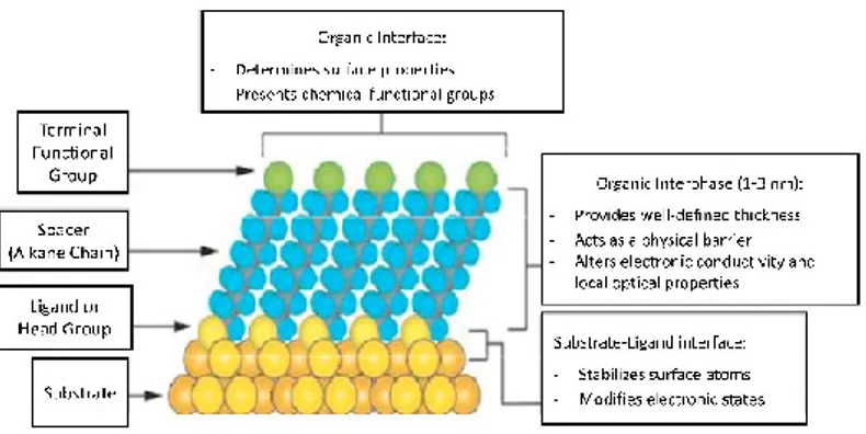
A scheme of an organic SAM array is shown in Figure 1.3. Usually, SAMs are formed spontaneously by dipping such substrates into an active solution, e.g. surfactant molecules R(CH2)nSiX3 (X = Cl, OCH3 or OC2H5) dissolved in
alkane/carbon tetrachloride solvent; however, the SAMs can be deposited by other techniques such as vapour deposition.
Figure 1. 3: A schematic diagram showing different parts of a self-assembled monolayer on a metal surface.
The self-assembling monolayer can be divided into three parts: 1) Head group. It forms the chemical bond with surface atoms of the substrate causing the pinning of surfactant molecule to the substrate.
2) Alkyl chain. The inter-chain van der Waals interactions could assist the formation of an ordered molecular structure. Of course, the possibility of obtaining ordered structures depends on the pinning density of the head groups.
3) Surface group. This is the terminal group which is replaced with or bonded to different functional groups to obtain specific applicative devices.
1.1.4 Characterization of SAMs
The quality of deposited SAMs is assessed determining their thickness, molecular orientation and/or ordering, uniformity of coverage, chemical composition, thermal and chemical stability.
Various techniques are available for the characterization of monolayers[17]. The chemical composition of monolayers can
be determined by Auger electron spectroscopy (AES), X-ray photoelectron spectroscopy (XPS) and secondary ion mass spectroscopy (SIMS). In particular, XPS is a reliable technique to settle the chemical composition of organic ultrathin layers on such substrates. In the XPS instrument, the photoelectrons that are able to escape from substrate’s surface are analysed with respect to their kinetic energy and the core level binding
energies of those electrons can be determined. Thanks to this technique it can be afford information about the chemical composition (elemental distribution and chemical state of the elements) of the examined sample.
1.2 Chemical Sensors
Since 80’s the interest on chemical sensors have been growing because of the widespread use of those systems in several areas of daily routine such us environmental monitoring, public security and food safety. Nowadays, the rising interest for this kind of technology is fostered by the increasing efforts in biochemical, bio-reactions and nanomedicine.
In fact, billions of dollars are spent in equipment related to medical diagnosis but usually those are cumbersome and time-consuming. Therefore, there is a pressing need towards cheaper and easier chemo/biosensors for the detection of various analytes in solution and atmosphere. Only few chemo/biosensors for simple analytes have been able to meet commercial requirements with detection sensitivity, selectivity, accuracy and reliability approaching that of experimental equipment. However, the recent developments of novel chemosensory materials and fabrication technologies
may provide many potential opportunities for the development of a new generation of chemo/biosensors. Thus, the explorations on chemo/biosensors based on novel sensing concept have attracted growing interest in recent years.[18]
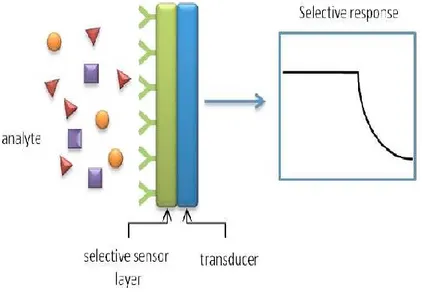
A chemical sensor is a device that transforms chemical information, ranging from the concentration of a specific sample component to total composition analysis, into an analytically useful signal.
Figure 1. 4: Working principle of supramolecular sensors.
property of the system.[19] The sensing material interacts with
a chemical species present in the environment, called analyte, by changing some of its physicochemical properties, while the transducer transforms these variations into a readable signal. The structure of a generic chemical sensor is shows in Figure 1.4.
Chemical sensors contain two basic functional units: a receptor part and a transducer part.
In the receptor part of a sensor the chemical information is transformed into a form of energy which may be measured by the transducer.
The transducer part is a device capable of transforming the energy carrying the chemical information about the sample into a useful analytical signal. The transducer as such does not show selectivity.
The receptor part of chemical sensors may be based upon various principles:
1) Physical, where no chemical reaction takes place. Typical examples are those based upon measurement of
absorbance, refractive index, conductivity, temperature or mass change.
2) Chemical, in which a chemical reaction with participation of the analyte gives rise to the analytical signal.
3) Biochemical, in which a biochemical process is the source of the analytical signal. Typical examples are microbial potentiometric sensors or immunosensors. They may be regarded as a subgroup of the chemical ones. Such sensors are called biosensors.
Chemical sensors may be also classified according to the operating principle of the transducer[20] in:
Optical devices, wich transform changes of optical
phenomena, which are the result of an interaction of the analyte with the receptor part. This group may be further subdivided according to the type of optical properties which have been applied in chemical sensors.
Electrochemical devices, wich transform the effect of the
electrochemical interaction analyte-electrode into a useful signal. Such effects may be stimulated electrically or may result in a spontaneous interaction at the zero-current
Electrical devices, based on measurements, where no
electrochemical processes take place, but the signal arises from the change of electrical properties caused by the interaction of the analyte.
Mass sensitive devices, wich transform the mass change at a
specially modified surface into a change of a property of the support material. The mass change is caused by accumulation of the analyte.
Magnetic devices based on the change of paramagnetic
properties of a gas being analysed. These are represented by certain types of oxygen monitors.
Thermometric devices based on the measurement of the heat
effects of a specific chemical reaction or adsorption which involve the analyte. In this group the heat effects may be measured in various ways, for example in the so called catalytic sensors the heat of a combustion reaction or an enzymatic reaction is measured by use of a thermistor.
Sensors are typically characterized by three properties:
Sensitivity can be generally defined as the slope of the
analytical calibration curve, that is correlated with the magnitude of the change in the sensor signal upon a certain change in the analyte concentration.[21] “Cross sensitivity”
hence refers to the contributions of other than the desired compound to the overall sensor response.
Selectivity is instead the ability of a sensor to respond
primarily to only one chemical species in the presence of different species (usually denoted interferents). The quest for better selectivity remains the main target of the chemical sensing research,[22] it can be achieved by using biosensors
(e.g. biologically derived selectivity by appropriate enzymes, structure-binding relationship in antibodyantigen complexes,) or by synthesizing materials containing specific binding sites.
Reversibility describes the sensor’s ability to return to its
initial state after it has been exposed to analytes and more in general chemical species. For the reversibility to take place it requires the formation of weak interactions, since the formation of covalent or ionic bonds would result in an irreversible saturation of the layer.[23]
The conventional design of chemical sensors uses a “lock-and-key” approach (a steric fit concept enunciated for the first time by Emil Fischer in 1894),[24] wherein a specific receptor
is synthesized to bind the analyte strongly and selectively. This concept has been widely exploited by supramolecular chemists for the design and synthesis of molecular receptors which are useful to understand and mimic nature specific interactions. As for biological systems, the concepts of shape recognition and the complementarity of binding site are central issue for effective molecular recognition in artificial host-guest systems. The efforts that have been done in seeking the best design in the field of synthetic receptors[25] allow
sensor selectivity modulation towards different classes of compounds by mastering the weak interactions that occur between the sensing material and the analytes. The selective binding of a neutral substrate by a molecular receptor to form a complex (molecular recognition) is based on shape complementarity and also on the presence of specific interactions such as hydrogen bonding,[26] stacking,[27] and
CH-π interactions.[28] Molecular recognition is a concept
really attractive and potentially powerful approach to engineering structures and devices at the molecular scale.[29]
Organic monolayers hosted on inorganic surfaces[30-35]
represent the best approach to use the full potential of molecular recognition on surfaces.[36,37] Compared to both thin
films and bulk materials containing molecular receptors, such hybrid organic-inorganic materials have the advantage of reducing or even eliminating non-specific interactions which often mask the recognition events.[38] There is a wide choice
of host molecules; such examples of very promising host system are: crown ethers, cavitands, cyclodextrins and calixarenes.
1.3 Environmental Remediation
Avoiding or limiting the inlet of contaminants or wastes in the environment should represent a fundamental aspect of life cycle in any industry, but, unfortunately, this is not always true. For this reason, today more than ever, there is an increasing quest for environmental remediation programmes by all media such as soil, groundwater, sediment, or surface water.[39]
Fortunately, taking care of the environment today is a sustainable challenge and nanomaterials represent a
pollutants. The interest for the application of such nanosystems in environmental remediation is raising so much that they coined a word to described this field of application, nanoremediation. During a nanoremediation process, a nanoparticle agent must be brought into contact with the target contaminant under conditions that allow a detoxifying or immobilizing reaction. This process typically involves a pump-and-treat process or in situ application.
Compared to conventional macroscale materials, nanomaterials exhibit significant improvements in surface area as a function of mass. Additionally, their colloidal size allows subsurface deployment via injection with the rapid treatment of aqueous contaminants at almost any location and depth in terrestrial groundwater systems.
Conceptually, the key properties required for the use of any engineered nanoparticle for in situ remediation of polluted groundwater are:
1) high reactivity for contaminant removal; 2) sufficient mobility within porous media; 3) sufficient reactive longevity;
4) low toxicity.
These properties are operational drivers and at the same time the material must be manufactured and deployed at a cost that is competitive with other existing technologies. Not many engineered nanoparticles fulfil the above mentioned requirements.
1.4 Enhanced Drug Delivery Systems
Targeted drug delivery is a very interesting field that in the last decade has been developing faster than ever. This method allows to deliver medication to a patient in a faster and more efficient manner increasing the concentration of the drug in some specific parts of the body.
Considering the fact that about 1.5 billion people worldwide suffer from brain diseases and moreover the growing demand for cancer therapies for a sick population, there is a clear need for a suitable strategy to deliver non-permeating therapeutic agents.[40,41]
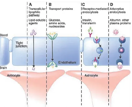
the cells or inability to cross the Cell Barrier. For example, most of the drugs systematically administered for chemotherapy do not gain access to the brain in the required concentration for tumours. It has been proposed that small molecules (molecular weight < 400 Da) with high lipophilicity that are not substrates for active efflux transporters, cross the BBB. However, more than 98% of small molecules do not meet these requirements to enter the brain. In addition, 100% of large molecules are unable to gain entry to this organ.
Figure 1. 5: Schematic representation of the mechanisms available to transport endogenous molecules across the BBB
In fact, compounds cross the BBB by means of active or passive mechanisms (Figure 1.5).
In passive targeting, the drug’s success is directly related to circulation time. This is achieved by cloaking the nanoparticle with some sort of coating. Several substances can achieve this, e.g. polyethylene glycol (PEG). By adding PEG, the surface of the nanoparticle turn to be hydrophilic, thanks to the
nanoparticle makes the substance antiphagocytic thus allowing to stay in circulation for a longer period of time.[42]
To work in conjunction with this mechanism of passive targeting, nanoparticles that are between 10 and 100 nanometers in size have been found to circulate systemically for longer periods of time.[43]
By contrast, the active targeting of drug-loaded nanoparticles enhances the effects of passive targeting to make the nanoparticle more specific to a target site. There are several ways in which this mechanism can be accomplished. Knowing the nature of the receptor on the cell is a way to target a drug, so a specific ligand can be utilized; this leads to bind specifically to the cell that has the complimentary receptor. Active targeting can also be achieved by utilizing magnetoliposomes, which usually serves as a contrast agent in magnetic resonance imaging (MRI).[44] Thus, by grafting these
liposomes with a desired drug to deliver to a region of the body, magnetic positioning could aid with this process.
Furthermore, a nanoparticle could possess the capability to be activated by a trigger that is specific to the target site, utilizing, as example, materials that are pH or redox potential
In order to achieve the goal of efficiently transport drugs inside the cell barrier, the approach largely used in nanomedicine plans to employ nanoparticle-mediated drug delivery strategy in order to avoid the downfalls of conventional drug delivery. The nanoparticles would be loaded with drugs and targeted to specific parts of the body where there is diseased tissue, thereby avoiding interaction with healthy tissue. Ideally the goal of a targeted drug delivery system should be to prolong, localize, target and have a protected drug interaction with the diseased tissue. The advantages are the reduction in the frequency of the dosages taken by the patients and the reduction of drug’s side-effects. The disadvantage of the system is the reduced ability to adjust the dosages.
1.5 Cavitands
Cavitands are a class of complex organic compounds that have been synthesized for the first time by Cram and co-workers whom define them as “synthetic organic compounds with enforced concave cavities large enough to complex
complexation properties have been extensively studied at solid state[46], in solution[47] and in the gas phase.
The concave surface allows the docking of different functional groups on the substrate binding sites theoretically inaccessible because located inside the cavity.[48]
Figure 1. 6: Structure of a cavitand top (left) and side(right) views
Cavitands are generally synthesized by covalent linkage of neighbouring phenolic hydroxyl groups in the corresponding octols. They are particularly attractive because the rim of the bowls can be varied with different R2 substituent and bridging
groups R3 for deepening the bowl cavity and for introducing
potentially cooperating functional groups to act as molecular receptors.[49] Moreover the R
1 substituent can be used for
to form host-guest complexes with a variety of guest molecules and ions through their rigid, concave π-basic cavity, which enables electrostatic interactions such as cation-π and CH-cation-π. In addition, appropriate substitution at the upper-rim allows them to employ hydrogen bonding in the formation of complexes.
The most common bridging groups are alkylenedioxy, dialkylsilicon, heterophenylene and phosphoryl.
In this thesis we focalized the attention on two kinds of cavitands: phosphourus-bridged, quinoxaline-bridged.
1.5.1 Quinoxaline-Salen-bridged cavitands
The cavity of resorcinarenes can be largely extended by bridging phenolic hydroxyl groups with aromatic spacers.[5051]
Tetraquinoxaline cavitands result from nucleophilic aromatic substitution with 2,3-dichloroquinoxaline on the phenolic oxydryl moieties of a resorcin[4]arene.
A peculiarity of these systems is the reversible switching between a closed “vase” conformation with a deep cavity for
flat extended surface.[52] Indeed the quinoxaline spacers can
occupy either axial (a) or equatorial (e) positions (Figure 1.7). In the “vase” (aaaa) conformer, the spacers touch each other via their hydrogens while forming a box like cavity with C4V symmetry which is approximately 7 Å wide and 8 Å deep.[53]
The cavity is open at the top and closed at the bottom by the cavitand itself. In the “kite” (eeee) conformer, the spacers are more or less in the same plane (C2v symmetry).
Conformational switching can be reversibly induced by temperature or pH changes (the “kite” conformation is preferred at low temperatures and low pH values), or by metal-ion addition.
Figure 1. 7: Structure of quinoxaline cavitand eeee conformer (left) and aaaa conformer (right)
In contrast, in mixed-bridged cavitands with one of the four quinoxaline wings displaced by a different bridge, the thermal
vase-to-kite interconversion is switched off by substantially decreasing of the solvation of the kite form. Mixed-bridged cavitands can therefore adopt only the kite conformation by protonation of the quinoxaline nitrogen atoms with an acid such as TFA, as a result of the developing Coulombic repulsion in the vase geometry.
New mixed-bridged triquinoxaline (3QxCav) are proposed as receptor for the realization of materials to be used as trapping devices for nitroaromatic compounds.
The receptor discussed in this thesis consists of a QxCav compound functionalized with four alkyne functionalities.
1.5.2 Phosphorous bridged Cavitands
The first attempt to synthesize phosphorous-bridged cavitands was carried out in Cram’s group in the ‘80s by reacting a methyl-footed resorcin[4]arene with
dichlorophenylphosphonate, obtaining a mixture of diastereomers difficult to isolate.[54]
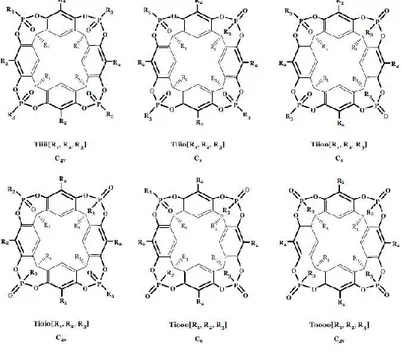
In fact, the presence of four Pv stereogenic centers paves the
and outward (o) configurations are defined relative to the different orientation of the P=O moieties (Figure 1.8)
Figure 1. 8: Isomers of tetraphosphonate bridged cavitands.
The tetraphosphonate cavitands nomenclature, reported in Figure 1.8, summarizes the number and relative positions of Pv
bridges, their stereochemistry, and the type of substituents at the lower rim, at the apical positions, and on the phosphorus bridges, respectively, in a single term.
In particular, the capital letter, defines number and nature of bridges, the lower case letters define the in-out stereochemistry, and R1, R2 and R3 in brackets define the
substituents at the lower rim, in the apical positions and on the phosphorous stereocenters respectively.
Tetraphosphonate cavitand presents remarkable recognition properties toward N-methylpyridinium (Kass ~107, Figure 1.9
a) and N-methylammonium (Kass ~109, Figure 1.9 b) which
can be attributed to three synergistic interaction modes: 1) N+•••O=P cation-dipole interactions;
2) CH3- interactions of the acidic +N-CH3 group with the
basic cavity;
3) two simultaneous hydrogen bonds between two adjacent P=O bridges and the two nitrogen protons,[55] in the case of
protonated secondary amines;
The simultaneous hydrogen bonds are the reason for the higher affinity of the N-methylammonium toward the cavity.
Figure 1. 9: Interactions involved in the molecular recognition process.
Another class of cavitand (TSiiii), structurally identical to the
4PO receptor except for the presence of four P=S instead of four P=O has been synthesized via oxidation in situ of the tetraphosphonite cavitand with S8.
This substitution strongly reduces the molecular recognition properties, because sulphur has lower electronic density with respect to the oxygen and consequently less affinity for H-bonding interactions.[56] In addition the cavity of TS
iiii is much
smaller and less prone to guest inclusion because sulphur is larger (atomic radius=1 Å) than oxygen (atomic radius=0.6 Å). (Figure 1.10)
Figure 1. 10: Comparison between tetraphosphonate (left) and tetrathiophosphonate (right) cavitands (top view).
1 J. Gao, B. Xu, Nano Today, 2009, 4, 37-51.
2 L. Zhang, T. J. Webster, Nano Today, 2009, 4, 66-80.
3 a) C. Bae, H. Yoo, S. Kim, K. Lee, J. Kim, M. M. Sung, H. Shin, Chem. Mater. 2008, 20, 756–767. b) G. R. Patzke, F. Krumeich, R. Nesper, Angew. Chem., Int.Ed. 2002, 41, 2446–2461. c) S. J. Hurst, E. K. Payne, L. Qin, C. A. Mirkin, Angew. Chem., Int. Ed. 2006, 45, 2672–2692. d) B. Tian, T. J. Kempa, C. M. Lieber, Chem. Soc. Rev. 2009, 38, 16–24.
4 Y. Qiu, P. Chen, M. Liu, J. Am. Chem. Soc., 2010, 132, 9644-9652. 5 J. C. Love, L. A. Estroff, J. K. Kriebel, R. G. Nuzzo, G. M. Whitesides, Chem. Rev. 2005, 105, 1103-1169.
6 Möbius, D. in Topics in Surface Chemistry (eds. Paul S., B. & Kay, E.)
8 W. C. Bigelow, E. Glass, W. A. Zisman, J. Colloid Sci. 1947, 2, 563. 9 E. E. Polymeropoulos, J. Sagiv, J. Chem. Phys. 1978, 69, 1836. 10 J. Sagiv, J. Am. Chem. Soc. 1980, 102, 92.
11 S. Onclin, B. J. Ravoo, D. N. Reinhoudt, Angew. Chem. Int. Ed. 2005, 44,
6282-6304.
12 C. Tidwell, S. Ertel, B. Ratner, B. Tarasevich, S. Atre, D. Allara, Langmuir 1997, 13, 3404-3414.
13 R. E. Holmlin, X. Chen, R. G. Chapman, S. Takayama, G. M. Whitesides,
Langmuir, 2001, 17, 2841-2850.
14 E. Ostuni, R. G. Chapman, M. N. Liang, G. Meluleni, G. Pier, D. E.
Ingber, G. M. Whitesides, Langmuir, 2001, 17, 6336-6343.
15 C. Engtrakul, L.R. Sita, Nano Lett., 2001, 1, 541-549.
16 J. J. Gooding, F. Mearns, W. Yang, J. Liu, Electroanal., 2003, 15, 81-96. 17 M. Kind, C. Woll Progress in Surface Science, 2009, 84, 230–278. 18 G. Guan, B. Liu, Z. Wang, Z. Zhang Sensors 2008, 8, 8291-8320.
19 A. Hulanichì, S. Geab, F. Ingman, Pure&App. Chern., Vol. 63, No. 9, pp.
1247-1250, 1991.
20 R. W. Cattrall, Chemical Sensors, Oxford Science Publications, 1997. 21 A. D’Amico, C. Di Natale, IEEE Sensors Journal 2001, 1, 183. 22 J. Janata, M. Josowicz, Anal. Chem. 1998, 70, 179.
23 A. Hierlemann, A. J. Ricco, K. Bodenhöfer, W. Göpel, Anal. Chem. 1999,
25 J.-M. Lehn, Supramolecular Chemistry, Wiley-VCH, Wienheim, 1995. 26 J. Rebek, Angew. Chem. Int. Ed., Engl., 1990, 29, 245-255.
27 C. H. Hunter, K. R. Lawson, J. Perkins, C. J. Urch, J. Chem. Soc., Perkin Trans. 2001, 2, 651-699.
28 M. Nishio, M. Hirota, Y. Umezawa, The CH-π Interactions, Wiley-VCH, NewYork, 1998.
29 G. M. Whitesides, B. Grzybowski, Science, 295, 2418.
30 M. Dubey, S. L. Bernasek, J. Schwartz, J. Am. Chem. Soc. 2007, 129, 6980–6981.
31 S. Zhang, C. M. Cardona, L. Echegoyen, Chem.Commun. 2006, 4461–
4473.
32 A. Facchetti, E. Annoni, L. Beverina, M. Morone, P. Zhu, T. J. Marks, G.
A. Pagani, Nat. Mater. 2004, 3, 910–917.
33 Z. Liu, A. A. Yasseri, J. S. Lindsey, D. F. Bocian, Science 2003, 302,
1543– 1545.
34 M. Altman, A. D. Shukla, T. Zubkov, G. Evmenenko, P. Dutta, M. E Van
der Boom, J. Am. Chem.Soc. 2006, 128, 7374–7382.
35 T. Gupta, M. E. Van der Boom, J. Am.Chem. Soc. 2006, 128, 8400–8401. 36 A. B. Descalzo, R. Martìnez-Màòez, F. Sancenòn, K. Hoffmann, K.
Rurack, Angew. Chem., Int. Ed. 2006, 45, 5924–5948.
37 C. Lagrost, G. Alcaraz, J.-F. Bergamini, B. Fabre, I.Serbanescu, Chem. Commun. 2007, 1050–1052.
39 Crane, R. A. & Scott, T. B. Nanoscale zero-valent iron: Future prospects
for an emerging water treatment technology. J. Hazard. Mater. 211–212, 112–125 (2012).
40 R. S. Dhanikula, A. Argaw, J. Bouchard, P. Hildgen, Mol. Pharm. 2008,
5, 105.
41 P. Blasi, S. Giovagnoli, A. Schoubben, M. Ricci, C. Rossi, Adv. Drug Delivery Rev. 2007, 59, 454.
42 Vlerken, L. E. V.; Vyas, T. K.; Amiji, M. M. Poly(Ethylene
Glycol)-Modified Nanocarriers for Tumor-Targeted and Intracellular
Delivery. Pharm. Res. 2007, 24, 1405–1414.
43 Gullotti, E. & Yeo, Y. Extracellularly activated nanocarriers: A new paradigm of tumor targeted drug delivery. Mol. Pharm. 6, 1041–1051 (2009).
44 Galvin, P. et al. Nanoparticle-based drug delivery: Case studies for cancer and cardiovascular applications. Cell. Mol. Life Sci. 69, 389–404 (2012).
45 Moran, J. R., Karbach, S. & Cram, D. J. Cavitands: synthetic molecular
vessels. J. Am. Chem. Soc. 104, 5826–5828 (1982).
46 D. J. Cram, S. Karbach, H.-E. Kim, C. B. Knobler, E. F. Maverick, J. L.
Ericson, R. C. Helgeson, J. Am. Chem. Soc. 1988, 110, 2229-2237.
47 a) J. A. Tucker, C. B. Knobler, K. N. Trueblood, D. J. Cram, J. Am. Chem. Soc. 1989, 111, 3688-3699. b) P. Soncini, S. Bonsignore, E. Dalcanale, F. Ugozzoli, J. Org. Chem. 1992, 57, 4608-4612. c) T. Haino, D. M. Rudkevich, A. Shivanyuk, K. Rissanen, J. Rebek, Jr., Chem. Eur. J. 2000, 6, 3797-3805. d) K. Paek, J. Cho, Tetrahedron Lett. 2001, 42, 1927-1929.
48 A. Friggeri, F.C.J.M. Van Veggel, D.N. Reinhoudt, Langmuir 1998, 14,
49 P. Timmerman, W. Verboom, D. N. Reinhoudt, Tetrahedron 1996, 52,
2663.
50 R. Boukherroub, S. Morin, D. D. M. Wayner, F. Bensebaa, G. I. Sproule,
J.-M. Baribeau, D. J. Lockwood, Chem. Mater. 2001, 13, 2002.
51 a) J.A. Bryant, J.L Ericson, D.J. Cram J. Am. Chem. Soc. 1990, 112,
1255; b) D.J. Cram, H.–J. Choi, J.A. Bryant, C.B. Knobler, J. Am. Chem. Soc, 1992, 114, 7748
52 P. Roncucci, L. Pirondini, G. Paderni, C. Massera, E. Dalcanale, V.A.
Azov, F. Diederich, Chem. Eur. J. 2006, 12, 4775.
53 E. Dalcanale, P. Soncini, G. Bacchilega, F. Ugozzoli, J. Chem. Soc. Chem., Chem. Commun 1989, 500.
54 K. D. Stewart, Ph.D. Dissertation, University of California, Los Angeles,
1984.
55 J. J. Lundquist, T. E. Toone, The Cluster Glycoside Effect, Chem. Rev.
2002, 102, 555-578.
56 A. G. Cullis, L. T. Canham and P. D. J. Calcott, J. Appl. Phys., 1997, 82,
Chapter 2: Cavitand monolayers on
metal oxides for environmental control:
VOC detection on functionalized ZnO
nanostructures
In this chapter the strategy for the fabrication of a hierarchical hybrid inorganic-organic system suited for the recognition of aromatic volatile organic compounds (VOC) on brush-like ZnO fibers is described. The hybrid material was obtained by a multi-step approach based on the growth of ZnO nanorods onto electrospun ZnO fibers. The ZnO nanostructures were functionalized through the grafting of a bifunctional phosphonic linker (12-azidodecylphosphonic acid) followed by the anchoring of a specific cavitand receptor. The linker was anchored on ZnO fibers through the phosphonic group whilst the azide terminations reacted with a quinoxaline-bridged cavitand (QxCav) having four alkyne groups via “click” reaction. Each reaction step was monitored by using XPS, FTIR and SEM. The recognition properties of this hybrid
were evaluated by XPS and Raman measurements. The obtained results confirmed the success of the overall synthetic approach which combines the recognition molecular properties of cavitand receptor with the peculiar characteristics of the brush-like ZnO nanostructure.
2.1 Introduction
ZnO is a very interesting material with unique physical and chemical properties, such as optical and electrical features and furthermore is nontoxic, inexpensive and has a high chemical stability. It is classified as a direct wide band gap semiconductor (3.37 eV at room temperature) and for this reason is one of the most promising materials for the fabrication of optoelectronic and gas sensing devices. Moreover, the possibility to easily built nanostructure from this material paves the way for the study of new properties that depend on shape and size.
Zinc oxide can occur in one- (1D), two- (2D) and three-dimensional structures. One-three-dimensional structures gather the
and -rings, -ribbons, -tubes, -belts, -wires and -combs. Nanoplates/nanosheets and nanopellets make up the 2D structures whereas examples of 3D structure include flowers, dandelions, snowflakes, etc. To date all those structures have been successfully synthesized but, as said before, one-dimensional nanostructures have caught researchers’ attention because of their wide range of potential applications.
With regard to 1D Zinc oxide, in the past years those nanostructures have been prepared by various method such as thermal evaporation, chemical vapour deposition (CVD), vapour-liquid-solid (VLS), metal organic vapour deposition (MOCVD), arc discharge and laser ablation.
2.2 Molecular recognition of aromatic volatile
organic compounds (VOCs)
Increased Volatile Organic Compounds (VOCs) emissions’ level and their impact on air quality is nowadays considered one of the most important environmental concern. [1-2] Those
compounds are man-made or naturally occurring highly reactive hydrocarbons. Natural origins of VOCs include
wetlands, forests, oceans and volcanoes but the majority of them are created from anthropogenic activities consisting of manufacturing or petrochemical industries and vehicular emissions. Indeed, some VOCs are well-known as highly toxic or carcinogenic in nature and may cause both short- and long-term impacts on human health as well as on the natural ecosystem. [3-4] For example, the benzene has a high potential
to damage humans in both specific (e.g., the stomach, kidneys, liver and spleen) and systematically (e.g., the nervous, reproductive, circulatory, immune, cardiovascular and respiratory systems) ways. Consequently, a number of major environmental safety agencies (e.g., National Institute of Occupational Safety and Health (NIOSH), Environmental Protection Agency (EPA), and European Agency for Safety and Health at Work (EU-OSHA)) have established guidelines to limit the exposure of humans to VOCs in indoor and workplace air in light of their effects on health. Furthermore, VOCs are known to be precursors of tropospheric ozone and for this reason, their emissions are limited by legislation in many regions so the detection and quantification of these molecules is critical. Highly sensitive analytical techniques
magnetic resonance, etc.) have commonly been employed for the accurate quantification of VOCs. However, these techniques display some drawbacks (e.g. high expenses, lack of portability, etc.), that constitutes a barrier for their use in everyday analysis. Moreover, such techniques often require complex and time consuming pre-treatment steps. Among alternatives, many sensor-based systems have been explored; using a wide range of detection principles, such as semiconducting metal oxides, conductive polymers, quartz crystal microbalance sensors and electronic nose, it is possible to achieve cheaper and compact devices. Nonetheless, such sensors generally suffer from sensitivity, selectivity and stability limitation. In this scenario I have investigated the possibility to modify such magnetic nanoparticles’ surface in order to decrease those limitations using specific molecules anchored by a multistep approach.
2.3 General Procedures
2.3.1 ZnO brush-like nanofibers preparation
A solution containing 2.7 g of PVP and 0.9 g of Zn(CH3COO)2∙2H2O in 9.5 mL of DMF was electrospun using
a commercial electrospinning system (EC-DIG Electrospinning, IME Technologies). The polymeric solution was stirred for 4 hours and loaded in a 5 mL plastic syringe tipped by a stainless steel needle. The solution was delivered using a flow rate of 5 μL/min. Electrospinning was carried out in ambient conditions (temperature 21 °C) and controlled relative humidity (40%). A positive bias of +19 kV was applied to the spinneret by a high voltage power supply. Silicon substrate were placed on a metallic collector and biased at -4 kV (distance needle - collector 16 cm). The electrical field applied to the drop formed at end of a syringe’s needle produced the nanofibers that were collected on the surface of the silicon substrates.
The Zn doped PVP nanofibers are used as template for deposition of a ZnO seed layer by MOCVD (Metal Organic Chemical Vapor Deposition). Deposition of ZnO seed layer was performed in a hot wall tubular reactor using a diamine (N,N,N,N′-tetramethylethylendiamine) (TMEDA) adduct of Zinc(II)bis(2-thenoyl-trifluoroacetonate) [Zn(tta) 2•tmeda].[5] A
slow temperature ramp up (5°C/min) was set to reach the deposition temperature (500°C) and deposition time was set at
carrier and reactive gas respectively. Pressure during deposition is ~2 Torr. Polymeric component is burned during seed layer deposition thus forming ZnO nanofibers on which the MOCVD seed layer was deposited. An external shell of ZnO nanorods is grown all around these nanofibers by Chemical Bath Deposition at atmospheric pressure and 80°C. Substrates were dipped face down in a nutrient bath containing a 0,025 M aqueous solution of zinc acetate dehydrate and ethylenediamine (EDA) and kept under mild stirring at 80°C for 6 hrs.[5] After CBD growth substrates were sonicated in
water for 1 minute to remove the ZnO microrods genereted in solution from homogeneous growth.[6]
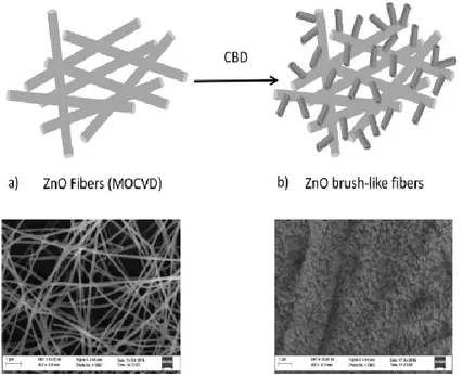
The procedure above described used to prepare ZnO brush-like fibers (bare ZnO fibers) which combines MOCVD and CBD (Chemical Bath Deposition) processes.[5] has been monitored
step by step through SEM analysis performed with LEO SUPRA 55VP equipped with a field emission gun. Figure 2.1a shows PVP electrospun nanofibers after ZnO seed layer deposition by MOCVD. After a slow temperature ramp up (from room temperature to deposition temperature set at 500°C), the polymer is degraded and the remaining ZnO fibers[7] act as scaffold for the following CBD process to grow
a brush-like ZnO nanorods external shell (Figure 2.1b). SEM image clearly evidences the morphological evolution of these hierarchically ZnO based structures from nanofiber mats to microsized tubular ZnO brushes, resulting from high density growth of ZnO nanorods. By comparing the fibre size in Figure 2.1a (~200 nm) and 1b (~2 μm) the estimated maximum length of ZnO nanorods is about 800 nm.
Figure 2. 1: Schematic representation of hierarchical ZnO fibers synthesis: a) ZnO fibers deposited by MOCVD onto Zn doped PVP electrospun nanofibers, b) brush-like ZnO nanorods grown by CBD
2.3.2 QxCav Synthesis
The synthesis of functional molecule to fix onto the nanostructured ZnO surface was carried out at the University
of Parma by the research group of Prof. E. Dalcanale
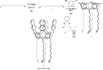
according the two steps pathway shown in Figure 2.2.
Figure 2. 2: Synthetic scheme for QxCav 3 with four ω-triple bonds at the lower rim.
The first step is the synthesis of resorcinarene that was performed adding 1.53 g, 9.3•10-3 mol, of aldehyde 1
(synthesized according to literature procedure[8]) to a stirred -3
mL) cooled to 0 °C, then 5.0 mL of HCl 36% was added dropwise. After 4 days of stirring at 55 °C, the mixture was allowed to cool to room temperature and poured into distilled water (450 mL). A precipitate formed, which was filtered, dried under vacuum and recrystallized from MeOH to give product 2 as a yellow pale solid (1.5 g, 64% yield). The product was then characterized by 1H NMR and ESI-MS and
the results are shown below:
1H NMR (400 MHz, 298 K, DMSO-d
6): δ (ppm) 8.87 (s, 8H,
ArOH); 7.16 (s, 4H, ArH); 6.14 (s, 4H, ArH) 4.21 (t, J = 7.6 Hz, 4H, ArCH); 2.69 (t, J = 2.6 Hz, 4H, CCH); 2.14 - 2.09 (m, 8H, CHCCH2); 2.07 – 1.90 (m, 8 H, CHCH2CH2); 1.50 – 1.10
(m, 48H, CH2).
ORBITRAP-ESI-MS: m/z calculated for C68H87O8 [M-H]-:
1031.6401. Found: 1031.6402 [M-H
]-The second step consists of tying up quinoxalinic groups on resorcinarene structure. To do this 0.6 g of K2CO3 (4.0•10-3
mol) was added to a solution made of 0.3 g resorcinarene 2 (2.9•10-4 mol) in 20 mL of dry DMF; the mixture was stirred at
stirred for 12 h at 85 °C. The reaction mixture was cooled to room temperature and quenched pouring it into 20 mL of 1N HCl solution. The resulting precipitate was recovered, washed with water and dried. The crude was purified thought flash chromatography (SiO2, CH2Cl2/EtAc 97/3) and recovered as
light yellow solid (0.6 g, 41% yield).
The product was then characterized by 1H NMR and
HR-MALDI-TOF and the results are shown below:
1H NMR (400 MHz, 298 K, CDCl3,) δ= 8.18 (s, 4H, ArH);
7.83-7.80 (m, 8H, ArH, part AA’ of an AA’BB’ system); 7.51-7.49 (m, 8H, ArH, part BB’ of an AA’BB’ system); 7.20 (s, 4H, ArH); 5.60 (t, J = 8.0 Hz, 4H, ArCH); 2.30 - 2.21 (m, 16H, CHCCH2 + CHCH2CH2); 1.99 (t, J = 2.5 Hz, 4H, CCH); 1.62
– 1.35 (m, 56H, CH2).
HR-MALDI-TOF: m/z calculated for C100H97N8O8 [MH]+:
1537,7429. Found: 1537.942 [MH]+
2.3.3 N
3-PA functionalized ZnO nanofibers
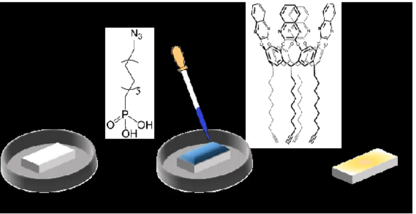
The ZnO brushes fibers were further functionalized by a multi-step approach shown in Figure 2.3. The first multi-step consists on the grafting of a phosphonic acid, bearing a terminal azide group, 12-azidododecylphosphonic acid (N3-PA). Thanks to
phosphonic group the linker was covalently grafted onto the bare ZnO nanofibers, forming a monolayer (N3-PA@ZnO)
through P–O–Zn [9] bonds.
The ZnO nanofibers were reacted using the droplet method [10-11], in order to avoid any degradation of the morphology of the
fibers, with 10 mM N3-PA solution in 2:1 1-butanol/ethanol for
5 hours, then rinsed thoroughly with neat solvent and dried under nitrogen flow.
Figure 2. 3: Reaction steps for the preparation of functionalized ZnO fibers.
2.3.4 QxCav click reaction
These QxCav molecules bearing four terminal acetylenic groups were then covalented bonded on the functionalized fiber
ascorbate (0.05 mmol) in THF(10 ml). The reaction was accomplished at 25 °C for 5 hours. The sample was then removed from the solution, washed with THF, three times, and dried under nitrogen flow. After click-chemistry, the surface shows a negligible degradation and morphology remains almost unchanged, as shown in Figure 2.4, where the hierarchical brush structure of fibres is well discernible (circled insert).
Figure 2. 4:brush-like ZnO nanorods after click reaction.
2.4 Sample characterization
XPS spectra were run with a PHI 5600 multi-technique ESCA-Auger spectrometer equipped with a monochromated Mg K X-ray source. Analyses were carried out with a photoelectron angle of 45° (relative to the sample surface) with an acceptance angle of ± 7°. The XPS binding energy (B.E) scale was calibrated by centering the C 1s peak due to hydrocarbon moieties and “adventitious” carbon at 285.0 eV.[12] SEM
analysis was performing with a LEO SUPRA 55VP equipped with a field emission gun. Transmission FTIR measurements were recorded on a JASCO FT-IR 430, with 100 scans collected per spectrum (scan range 400-4000 cm–1, resolution 4
cm–1). X-Ray powder diffraction (XRD) measurements were
performed with a θ-θ 5005 Bruker-AXS diffractometer (Zeiss, Oberkochen, Germany) using Cu Kα radiation operating at 40 kV and 30 mA.
Raman spectra have been taken by using a Witec Alpha 300 spectrometer. Acquisition were performed with a Nd:YAG 532
nm laser exiting radiation radiation with power densites below 1 mW to avoid heating effects.
2.4.1 XRD characterization
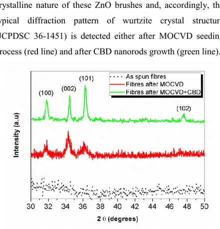
XRD measurements reported in Figure 2.5 clearly indicate the crystalline nature of these ZnO brushes and, accordingly, the typical diffraction pattern of wurtzite crystal structure (JCPDSC 36-1451) is detected either after MOCVD seeding process (red line) and after CBD nanorods growth (green line).
Noteworthy, the expected texturing along the (002) plane cannot be detected,[13] due to the brush-like structure of the
sample. However, it is clear from the detail in the insert of Figure 2.4 that ZnO nanorods grow perpendicularly and well aligned all around the tubular ZnO nanofibers surface.
2.4.2 FT-IR characterization
All ZnO nanofibers, bare ZnO fibers, N3-PA@ZnO and
QxCav-N3-PA@ZnO have been characterized by FT-IR and
XPS. Figure 4 shows the FTIR spectra comparison of bare ZnO fibers, N3-PA@ZnO and QxCav-N3-PA@ZnO. In particular,
two spectral regions are reported: (a) the C–H stretching region between 3200 and 2800 cm–1 and (b) the N
3 – alkyne stretching
region between 2200 and 2000 cm–1. The spectra in the 2200
and 2000 cm–1 region show for both N
3-PA@ZnO and
QxCav-N3-PA@ZnO a band at 2120 cm-1 absent in the spectra of bare
ZnO. In the case of N3-PA@ZnO, this feature is clearly related
to the characteristic absorption peak of the azide group, thus suggesting that the anchoring process preserves the active groups. After the click reaction, the decreasing of the azide band in QxCav-N3-PA@ZnO spectra indicates the proceeding
group to triazole. Note in addition that the further broadening of the band is due to the stretching of C≡C group of un-reacted termination of the bonded QxCav molecules. The C-H stretching region between 2800–3200 cm–1 shows for N
3
-PA@ZnO the appearance of C-H stretches compared to the bare ZnO. However, a significant increase in intensity of CH2
stretching at 2930 and 2850 cm–1 is observed in the spectra of
QxCav-N3-PA@ZnO, compared to N3-PA@Zn, reflecting the
increased number of CH2 groups related to the presence of the
QxCav alkyl chains. In addition, the surface anchoring of QxCav is confirmed by the presence of the peak at 3060 cm-1
in the QxCav-N3-PA@ZnO sample, diagnostic of the stretches
Figure 2. 6: FT-IR spectral regions in the 3200–2800 cm-1 (left) and 2200–2000
cm-1 (right) ranges of a) bare ZnO fibers, b) N
3-PA@ZnO and c) QxCav-N3
-PA@ZnO
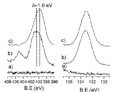
2.4.3 XPS characterization
regions of bare ZnO, N3-PA@ZnO and QxCav-N3-PA@ZnO
samples are shown in Figure 2.7. The presence and the position of the P2p band is a reliable indicator to evaluate the phosphonic acid grafting process. The P2p peak of N3
-PA@ZnO (absent in the bare ZnO nanofibers) is observed at 133.2 eV: this value is typical of phosphonic acids on transition metal oxide surfaces anchored in a bidentate way.[16]After
QxCav grafting, the P2p band of QxCav-N3-PA@ZnO is still
centred at 133.2 eV, thus indicating that the anchored phosphonic acid is not removed by the click reaction. As expected, bare ZnO nanofibers do not show any signal in the N1s spectral region whereas in the N3-PA@ZnO sample, two
N1s bands are observed: a main broad band around at 400.8 eV and a lower peak at 405.1 eV. The latter can be associated to the positively charged N atom of the N=N+=N- azide
resonance structure, while the envelope around 400.8 eV is due to the convolution of neutral and negatively charged N atoms.[17] Note that the intensity of the component at about
405.1eV decrease after prolonged XPS irradiation. After QxCav grafting, the N1s peak was observed at 399.8 eV, shifted towards lower binding energies (B.E.). The observed B.E. value is consistent with the presence of the quinoxalinic
ring nitrogen’s atoms. Moreover, the signal corresponding to electron deficient N atom of the azido group at 405.1 eV disappeared, indicating that the azide group is consumed in the formation of the triazolic ring, whose signal at 401.0 eV[17-18] is
superimposed with the broad band centred at 399.8 eV.
Figure 2. 7: High resolution N1s (left) and P2p (right) XPS spectral regions of a) bare ZnO, b) N3-PA@ZnO and c) QxCav-N3-PA@ZnO
2.5 Sensing Test
Gas−solid complexation tests were performed exposing QxCav-N3-PA@ZnO and N3-PA@ZnO (as inactive reference)
fluorine-marked compound to test the affinity of decorated-surfaces towards aromatic VOCs. The presence of the F1s band in the XPS spectra of QxCav-N3-PA@ZnO (Figure 2.8) after
exposure to the TFT vapours proved the complexation capability of the cavitand-functionalized surface. The absence of the halogen signals on N3-PA@ZnO (Figure 2.8) rules out
the possibility of physisorption due to unspecific interactions between the guest and the ZnO surface.
Raman spectra are reported in Figure 2.9 and validate the successful use of the functionalized ZnO brushes to detect aromatic compound, as TFT. The Qx-Cav and TFT main Raman peaks are reported for comparison.
Figure 2. 8: F1s spectral regions of a) N3-PA@ZnO and b) QxCav-N3-PA@ZnO
Figure 2. 9: Raman Spectra of QxCav-N3-PA@ZnO after exposure to TFT vapours
(red lines) and after TFT release (black lines). QxCav (blue line) and TFT (magenta line) compounds were added as reference.
The spectra display several active modes, attributed to both Si substrate, ZnO brushes, linked cavitand and TFT analyte. Accordingly, Raman spectra of bare QxCav and TFT (dropped
on silicon) are reported for comparison. The recorded spectra exhibit two main characteristic bands in the spectral region between 1000 and 2000 cm-1: the first order G mode (E2g
symmetry) at ~1600 cm-1 is attributed to sp2 graphitic network,
while the D mode (A1g symmetry) at ~ 1350 cm-1 reflects the
disorder and defects in the carbon lattice. The presence of these bands is due to carbonaceous residues of thermal degradation of PVP during MOCVD seed deposition. The sharp peak at about 1400 cm-1 is attributed to C-H bending mode of grafted
cavitand while the one at 3070 cm-1 belongs to C-H stretching
of analyte. After exposure to TFT atmosphere, the peak at 3070 cm-1 appeared in the Raman specrum of the material.
Noteworthy, this last signal disappears after desorption of TFT out from functionalized ZnO brush-like nanofibers, performed by flowing warm N2 for 15 minutes.
2.6 Conclusions
In this chapter, I reported on the synthesis and characterization of a new sequentially-grown nanostructured material consisting of brush-like ZnO nanofibers covalently functionalized with
performing MOCVD and CBD processes on electrospun ZnO nanofibers used as substrate for column growth. The columnar nanostructures were coated with an azidophosphonic acid monolayer, which acts as linker for the anchoring of a QxCav receptor functionalized at the lower rim with 4 terminal alkyne moieties. The efficiency of the grafting methodology was monitored by SEM, FT-IR and XPS. The hierarchical structure of the obtained material, whose morphology is not affected by the functionalization routes, is clearly shown by SEM analysis. FT-IR and XPS indicate that the phosphonic linker is covalently bound to the surface leaving N3 groups intact and
suited for receptor anchoring. QxCav is grafted to the monolayer coated nanostructure via click-reaction. The reaction evolution was monitored through the consumption of N3 groups, shown by the decrease of azide related FT-IR and
XPS signals.
Gas-solid complexation tests were monitored through complementary techniques, namely surface sensitive XPS and bulk Raman spectroscopy. Results indicate that the inherent recognition properties of the QxCav receptors towards aromatic analytes are retained after their anchoring, showing that this is a suitable way to convey recognition properties to
organized nanostructured materials. Further studies must be performed to optimized the signal transduction even though the Raman spectroscopy could be easily performed.
1 Stebounova LV, Morgan H, Grassian VH, Brenner S. Health and safety implications of occupational exposure to engineered nanomaterials. Wiley Interdiscip Rev. Nanomed. Nanobiotechnol. 2012; 4:310–21.
2 Ashford NA, Caldart CC. Government regulation of environmental and occupational health and safety in the United States and the European Union. In: Levy BS, Wegman DH, Sokas R, Baron S, editors. Occupational and environmental health: recognizing and prevent- ing disease and injury. 6th ed. Oxford UK: Oxford University Press; 2010. p. 640–63.
3 Atkinson R. Atmospheric chemistry of VOCs and NOx . Atmos Envi- ron
2000; 34:2063–101.
4 Kim KH, Jahan SA, Kabir E. A review of breath analysis for diagnosis of human health. Trends Anal Chem 2012; 33:1–8.
5 Fragalà, M. E.; Aleeva, Y.; Malandrino, G. Effects of Metal-Organic Chemical Vapour Deposition grown seed layer on the fabrication of well aligned ZnO nanorods by Chemical Bath Deposition. Thin Solid Films
6 Fragalà, M. E.; Aleeva, Y.; Malandrino, G. ZnO nanorod arrays fabrication via chemical bath deposition: Ligand concentration effect study. Superlattices and Microstructures 2010, 48, 408-415.
7 Di Mauro, A.; Zimbone, M.; Scuderi, M.; Nicotra, G.; Fragalà, M. E.;
Impellizzeri, G. Effect of Pt Nanoparticles on the Photocatalytic Activity of ZnO Nanofibers. Nanoscale Res Lett. 2015, 10, 484-490.
8 Cheng, X.; Li, L.; Uttamchandan, M.; Yao, S. Q. In Situ Proteome Profiling of C75, a Covalent Bioactive Compound with Potential Anticancer Activities. Org. Lett. 2014, 16, 1414−1417.
9 Smecca, E.; Motta, A.; Fragalà, M. E.; Aleeva, Y.; Condorelli, G. G. Spectroscopic and Theoretical Study of the Grafting Modes of Phosphonic Acids on ZnO Nanorods. J. Phys. Chem. C 2013, 117, 5364−5372.
10 Wang, X.; Liu, L.; Luo, Y.; Zhao, H. Bioconjugation of Biotin to the Interfaces of Polymeric Micelles via In Situ Click Chemistry. Langmuir
2009, 25, 744−750.
11 Cao, Y.; Galoppini, E.; Reyes, P. I.; Lu, Y. Functionalization of Nanostructured ZnO Films by Copper-Free Click Reaction. Langmuir 2013, 29, 7768−7775.
12 a) I. L. Swift, Surf. Interface Anal. 1982, 4, 47–51. b) D. Briggs, G. Beamson, Anal. Chem. 1992, 64, 1729–1736.