Università degli Studi di Catania
Dottorato di Ricerca in Fisica
XXVII Ciclo
Paolo M. Sberna
Novel Approaches to Photoactive Nanostructured
Materials for Efficient Solar Cells
Tutor: Prof.ssa Francesca Simone
Supervisors: Prof.ssa Elvira Fortunato
Dott.ssa Maria Miritello
Dott. Salvatore Mirabella
Coordinatore: Prof. Francesco Riggi
Tesi per il conseguimento del titolo
Dicembre 2014
i
List of abbreviations
ARC: anti-reflection coating CSP: concentrating solar power CVD: chemical vapor deposition
EF: Raman intensity enhancement factor
EF-TEM: energy filtered transmission electron microscopy EROI: energy return on investment
FE-SEM: field emission scanning electron microscopy FWHM: full width half maximum
GDP : gross domestic product
ICT : information and communications technology MG: metallic grating
MNP: metallic nano-particle NP: nano-particle
NS: nano-structure NW: nano-wires
PBG: photonic band gap PC: photonic crystal
PDOS: photon density of states
PERL solar cell: passivated emitter rear locally diffused solar cell PNJ: photonic nano-jet
PV: photovoltaic QD: quantum dot
ii QE: quantum efficiency
RBS: Rutherford back scattering spectrometry TEM: transmission electron microscopy XRD: X-ray diffraction
iii
List of symbols
fe(E): Fermi distribution Ef : Fermi energy K: Boltzmann constant T: absolute temperature
ne: density of electrons in the conduction band nh: density of holes in the valence band ni: intrinsic electron density
NC: effective density of state in the conduction band NV: effective density of state in the valence band EC: conduction band edge level
EV: valence band edge level Eg: band gap F: free energy E: energy S: entropy N: number of particles Ee: electron energy Eh: hole energy p: pressure V: volume µ: chemical potential φ: electrical potential
iv
ζ: electro-chemical potential h: Planck constant
ħ: reduced Planck constant ω: frequency
Ω: solid angle J: current density η: efficiency
Rr: radiative recombination rate Rnr: non-radiative recombination rate P: power
B: light trapping factor
t: time
n: refraction index
S(λ): solar cell spectral response R(λ): reflection coefficient T(λ): transmittance α: absorption coefficient A: absorptivity
ε: dielectric constant (ε = Re[ε] +i∙Im[ε]) a: polarizability
ξ: electric field p: dipole moment k: wave number
Contents
Chapter 1- ENERGY: RESOURCES AND TECHNOLOGIES
1.1 Introduction: basic concepts and consumption...1
1.2 Non-renewable resources...5 1.2.a Oil...5 1.2.b Coal...5 1.2.c Gas...6 1.2.d Nuclear...6 1.3 Renewable resources...7 1.3.a Hydropower...8 1.3.b Wind...8
1.3.c Concentrating solar power...8
1.3.d Photovoltaic...9
1.3.e Solar fuels...9
1.4 Perspectives...12
1.5 Solar cells fundamentals...14
1.6 Outline of the work...23
Chapter 2- LIGHT TRAPPING FOR PHOTOVOLTAICS
2.1 Antireflection coatings...26
2.2 Light trapping by surface texturing in the ray-optics regime...28
2.3 Light trapping approaches for thin-film solar cells...31
2.4 Fabrication of nanostructures...38
2.5 Efficient light trapping in silicon nano-wires produced by catalyzed chemical vapour deposition...40
2.5.a Synthesis...40
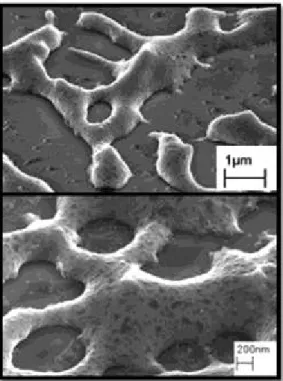
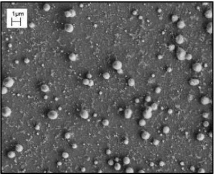
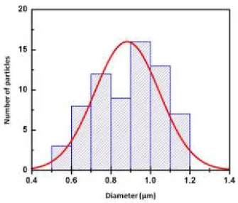
2.5.b Morphologic characterization...41
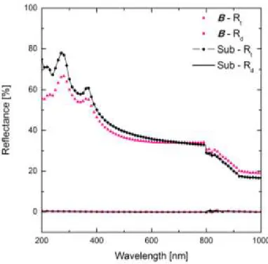
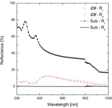
2.5.c Spectrophotometric characterization...42
2.6 Thin-film dewetting...45
2.7 Pulsed laser induced dewetting for semiconductor and dielectric nano-structures - Fundamental concepts for a novel approach ...49
2.8 Enhanced light scattering in silicon nano-structures produced by pulsed laser irradiation...51
2.8.a Synthesis...51
2.8.b Laser treatment...52
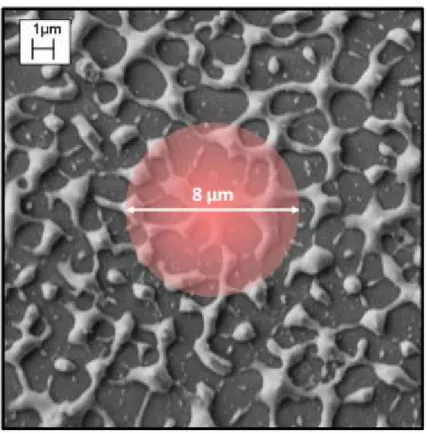
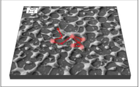
2.8.c Morphologic characterization...53
2.8.d Rutherford backscattering spectrometry...58
2.8.e Raman spectroscopy and optical characterization...60
2.9 Conclusions...68
Chapter 3 - CUPROUS OXIDE
3.1 Introduction...71
3.2 Bulk properties...74
3.3 Thin-films deposition methods...81
3.4 Doping: an overview...83
3.4.a Electrical conductivity modulation by doping...83
3.4.b n-type doping...84
3.4.c Doping effects on the optical band gap...87
3.4.d Doping effects on the copper oxidation state...89
3.4.e Doping effects on the minority charge carriers lifetime...89
3.5 Cu2O thin films synthesized by RF sputtering...91
3.5.a Synthesis...91
3.5.b Structural characterization...94
3.5.c Optical characterization...97
3.5.d Electrical characterization...102
3.6 Nitrogen doping of sputtered Cu2O thin films...104
3.6.a Structural characterization...106
3.6.b Optical characterization...107
3.6.c Electrical characterization...108
3.7 - Cu2O thin films synthesized by spray pyrolysis...112
3.7.a Synthesis...112
3.7.b Structural and morphologic characterization...117
3.7.c Optical and electrical characterization...122
3.8 Zn, Mg and Ca doping of Cu2O thin films deposited by spray pyrolysis...125
3.8.a Synthesis and structural characterization...125
3.8.b Optical and electrical characterization...132
3.8.c Conclusions...136
Bibliography...137
List of publications...140
International conferences...141
1
1 - ENERGY: RESOURCES AND TECHNOLOGIES
1.1 - Introduction: basic concepts and consumption
The eminent scientist R. Feynman wisely stated that humans have no knowledge of what energy is. This challenging remark could sound curious considering that nowadays Mathematics, Physics and Engineering provide the theoretical instruments, the concepts and the practical notions to attain a deep and broad understanding of the mechanisms which govern energy transformations and production. Such a lack of general knowledge and awareness of this issue would be due to the fact that the concept of energy permeates all the rules of the Universe, from the fundamental ones to the laws of the upper complex levels. Even though this issue is extremely intricate, it is needed to initially focus on drafting some energy concerning notions and ideas not only to offer a stimulating taste of first principles but mainly to furnish a basal frame for the themes dealt in this thesis.
The first intuitive feeling of energy is that it makes things happen through changes of states and transformations; thus energy is closely connected with another elusive concept, that is time. Specifically, quantum physics proffers a fascinating picture about energy and time connection. The second simple perception is that energy is the capacity of a system of producing work: i.e. exerting a force for a certain distance. From the first idea the concept of energy related to movement of bodies (kinetic energy and thermal energy) together with the concepts of energies associated to absorption and decays of systems (electro-magnetic energy) come out. Whereas from the second idea the notion of potential energy in all its forms (mechanical, nuclear, chemical and electrical) emerges. At the beginning of the last century, A. Einstein discerned and demonstrated that energy and mass are two different forms of the same stuff. Hence energy is so intimate to things that it constitutes also their essence. Energy cannot be created or destroyed. It can be transformed from a given type to another form by means of various processes and reactions which human-kind has learnt to exploit and control since its rise. The numerous forms of energy are not equivalent according to the perspective of technological uses and human purposes. Some kinds of energy are easily marketable (so valuable), as electrical energy, other ones are fruitless, as low temperature dissipated heat. Between these extremes there is a group of energy forms (mostly embodied in natural resources) that cannot be efficiently utilized directly. Thus they have to undergo conversions or secondary resources, which are more profitable and useful, have to be extracted by refining
2 processes. Extraction, refining and conversion require the consumption of energy and according to the laws of thermodynamics, are inexorably accompanied by a loss of a fraction of the primary energy quantity.
The parameter that quantify the above issue is the EROI (energy return on investment) calculated as the ratio of the amount of usable energy acquired from a resource to the amount of energy expended to make it available [1]. The estimation of EROI is incredibly complicated, since has to take into account scientific, economical and political aspects which generally are greatly entangled, for instance the concentration of energy stored into a given natural resource, the technological know-how to gain it, the geographic location and the associated political situation. The greater the EROI of an energy resource is than unity, the more such supply can be extensively used and pervasively spread. It is worth to specify that EROI, as most of typical parameter does not consider ecological (green house effect) and ethical matters, often arising from that resource exploitation.
The global amount of used energy (from a set of resources) is modulated by the total EROI generally in a direct manner. On the other hand, the modulation, dependent on the society needs, is a chaotic (in the mathematical sense), thus usually not fully predictable, trend. This chaotic behaviour is caused by the energy demand being in turn subject to energy availability (deterministic parameter) and life style (non-deterministic parameter). The mutual interplay between energy consumption and demand is a matter of the most advanced economical models.
Despite the fact energy consumption versus demand is, at short time scale, a complex function, a fast schematic tour in the energy use in the history could give a glance of the global trend.
From the rise of the first primitive societies up to 8.000 years ago the utilized energy sources were man power (80 W/person on the average) and biomass (mainly wood) [1]. Gradually, agriculture labour, craft activities and trade efficiencies were boosted by the exploitation of animal power (up to 800W/animal). Later with the advent of technological breakthroughs, men learned to gain mechanical energy from wind and water. Both compared to the above sources resulted more intensive, cheaper and with extended flow. Pushed by the appearance and development of the Industrial Revolution, coal progressively substituted wood as energy supply, the former having, since the XIX century, a higher EROI. When the energy stored by fossil fuels, such as gas and oil became accessible, men started to own a more versatile energy form, that could be spent for faster transportation and to improve the agricultural and industrial outcomes. Since the beginning of the last century, coal, gas and oil energy supplies, combined with the alternate current generation, made electricity one of the most
3 utilized energy form. In the last decades, whirling increase of information and communications technology (ICT) pervasiveness (it accounts for 10% of the total electricity consumption [1]) together with other comforts, like air conditioning, have been coercing modern developed society to be dramatically addicted to 24 h electricity thirst. Similarly, the exploitation of the chemical energy coming from oil has the same terrific proportions of the electricity use. As conclusion of this brief historical survey, it is important to underline that the gigantic energy consumption rate, sustained (but followed as well) by technological and life standard improvements, have been belonging to the tiny minority of the world rich population. This statement is further confirmed by the fact that the gross domestic product (GDP) per capita trend generally follows the same one of the energy use per capita [2].
Therefore it can be concluded that worldwide energy consumption rate is a continuously growing parameter (energy use per year increase factor / population increase factor = 6) [2]. Its destiny of inexorable exploding parameter is now reinforced as future perspective by the following points:
In this century several billion more people will join us. Hence if the current world average per capita power use is considered the present demand growth will be roughly of the 50%2.
On average, the populations of the fast growing economies is going to reach the life standards, thus the energy consumptions, of rich countries. This factor will enhance the former one.
The attempts to improve the efficiency of energy transformations, storage and usage are not enough to mitigate the previous two factors.
Even though the evolution of energy extraction and transformation have taken advantage by novel scientific and technological approaches, during all the years following the industrial revolution, the various usable forms of energy (mainly non-renewable) were treated simply as a commodity with endless supply and no long-term environmental/social impacts[1]. In other words the consumption philosophy of early men burning a bunch of wood trunks to light up a small village has not changed until now, where human activities take place at a scale, large enough to influence the planet as a whole. This problem is reflected, for instance, by the lack of controls, measurements and optimization of the power flow through the grid, which looks basically the same as that built a century ago. Hence the approach to the consumption of resources is essentially parasitic rather than symbiotic and, as it is well known from biology, parasites always kill the guest. Shifting our current socio-economic infrastructures to a sustainable system is a compelling and urgent transition whose strategy could be summarized in these five points:
4 Increase the efficiency of energy use.
Enlarge the availability and reliability of low carbon emission energy supply. Improve the efficiency of energy conversion and storage technologies.
Match the renewable energy flows, which are fixed and dilute, with the power densities of energy uses in modern society.
Tailor a global cooperation to push such transition by means of effective policies, business models and life standards.
Recycling of critical materials.
Further details and a deeper insight of these issues will be provided in the next sections.
5
1.2 - Non-renewable resources
1.2.a - Oil
The existing types of oil are classified into two groups: conventional oil (liquid oil accumulated in deep reservoirs, called fields) and unconventional oil, including heavy oils, oil sands (tar sands) and fine-grained sedimentary rock containing mixed organic chemical compounds (oil shale). According to some estimates, there is as much oil shale as the total global conventional oil endowment [1]. In most conventional oil fields, the recoverable fraction by drilling and pumping is around 60% of the total stored(1). Unconventional sources mining is generally a more expensive extraction method (40% of the initial energy is wasted in production [1]), causing severe environmental damages. Crude oil must be processed to become a wide variety of usable products. Oil refining is the most energy intensive industry, where energy consumption can reach half of the operating costs [1]. The advance in sophistication of extraction technologies and geological investigations is opening the access to new resources; nevertheless being oil a finite good, according to Hubbert's model [1], the global oil production is a bell shaped function of time, thus after reaching a peak of production, it inexorably will decrease. Today oil accounts for 40.8% of total world energy use [3], and at present demand conventional reserves would last for less than 100 years [2]. However oil shale energy potential is estimated to be 3∙104 TW∙year [2]. The prominent utilization comes from transports [3], a sector hardly supplied by renewable energy sources because of the current logistic organizations.
1.2.b - Coal
Coal is today the second primary energy supply (28.8% share [3]). Coal production should follow the Hubbert curve even though the global reserves are expected to last for centuries. Since the conversion technologies are mature, coal-based energy generation is cost effective. The main output is electricity for industries (80.7% of the total share [3]). In terms of sustainability the most urgent issue is its environmental impact, indeed 1 KWh electric energy produced by coal burning emits in the atmosphere more than 1 Kg of carbon dioxide followed by non negligible amounts of other pollutants [2]. However, thanks to the coal consumption being concentrated in big burning facilities, carbon dioxide capture systems could be integrated [1].
6
1.2.c - Gas
As for oil, there are unconventional (that is more difficult to exploit) gas resources such as gas hydrates which are bulky ice lattice trapping methane molecules (1 CH4 for
every 5.75 H2O) [1]. Nowadays, natural gas total energy share is the third (21.3% [3]).
The main gas use is for residential heating and cooking (44.2% [1]), yet electricity gas-based production is growing, being gas combustion the cleanest among fossil fuels (0.5 Kg of CO2 per 1 KWh [2]). It has been estimated that gas peak world production
would occur in the next decades. A promising alternative is methane hydrates exploitation, which would have a potential of 2∙104 TW∙year.
1.2.d - Nuclear
Nuclear energy is liberated in the form of thermal energy through the controlled fission reaction, in which U235 nucleus (that is the fissile isotope constituting 0.7% of the total uranium [1]) is split into smaller radioactive nuclei upon collision with a neutron. Nuclear power plants generate electrical energy (11.7% of share [3]) operating two possible fuel cycles:
Open fuel cycles: uranium is used only once and it is disposed directly. Nuclear energy potential, considering this method, the current production and the estimated uranium resources would be only 370 TW∙year [2]. The majority of operating plants use this method.
Closed fuel cycles: in this case the used nuclear fuel is reprocessed (breeding) to recover and use the remaining fissile fuel (95% is not used during first burning [2]) facilitating the waste management. The efficiency of this method could enhance the nuclear energy potential to 7400 TW∙year [2].
Nuclear fission energy is affected by the following drawbacks:
The problem of disposition of long-living and radioactive waste is still practically unsolved;
Risk that weapons usable material could be produced; Safety and security risks;
Power plants installation is extremely capital intensive.
Decommissioning and dismantling of power plants are generally at least one order of magnitude greater than the construction costs.
Because of the pressure exerted and the doubts rose by these issues, nuclear electricity generation globally is decreasing (2% in 2007 [1]).
7
1.3 - Renewable resources
The outer boundary of Earth atmosphere is invested by 1368 Wm-2 of solar radiation intensity [1]. This solar radiation power, crossing the atmosphere, is strongly attenuated by many scattering and absorption processes. The intensities absorbed by oceans and continents are respectively 170 Wm-2 and 180 Wm-2 [1], which integrated over the entire surface give a total absorbed power of 90 PW [1] (65 PW only for water [1]). Such an endless (on a human scale) huge power supply is 6000 times higher than the recent power demand (15 TW). Land and ocean phytomass is sustained by photosynthesis, which is powered by only 1% of the solar flux reaching the Earth surface [1]. Similarly, air circulation and winds utilize 1% of the same flux [1]. Then, about one fourth of the total power absorbed by seawater sustains the global water cycles [1]. Therefore Sun power, in addition to constitute a renewable energy source itself, feed the processes in the cycles at the bases of numerous renewable supplies such as hydro-power and wind energy. An overview of the solar energy transformations is shown in Fig. 1.1.
The following section provides general description and the relevant issues of the currently most effective renewable energy technologies.
8
1.3.a - Hydro-power
Hydro-power generation is based on the conversion of the mechanical potential energy of water stored in large high basins firstly into kinetic energy (falling water) and finally by turbines, into electricity. Systems linked to huge water artificial reservoirs have capacities ranging from few mega-watts to several gig-watts. Few kilo-watts up to some mega-watts can be produced for local demand by small systems not involving water reservoirs. Hydro-electric generation efficiency reaches 90% [1], dwarfing thermonuclear (33%) [1]. For this reason, 16% of the global electricity demand is covered by hydro-power [3], which is the largest exploited source. Moreover the systems can be designed either to generate power or to store energy, pumping water to high levels. Hydro-power related drawbacks are:
Vulnerability to climate changes affecting water cycle. Invasiveness in terms of used area by water reservoirs.
Nevertheless hydro-power stations, in parallel, can provide irrigation water and navigation advantages.
1.3.b - Wind
Wind kinetic energy is transformed into electricity by horizontal axis turbines kept at elevated heights to face not dragged fast wind (operating speed ranges from 7 – 15 m/s [1]). Since wind must keep on flowing after crossing the turbine blades to carry on their rotation, the theoretical generation efficiency limit is 60% [1], yet operating efficiencies are between 30% – 40% [1]. Installation and dismantling are cheaper and faster the relative operations of any other electric technology [1]. Wind is the world fastest growing technology, whose capacity reached 38 GW in 2009 [1]. Recent estimates indicates that a feasible turbines networks could provide an electricity budget forty times bigger than the amount currently consumed [1]. The biggest disadvantages of connecting wind energy to the present grid are intermittency and instability of supply.
1.3.c - Concentrating Solar Power
Solar radiative energy can be indirectly converted into electricity concentrating diluted sun light, by means of wide reflectors, onto a small absorbing area to obtain at least 300 °C for turbine moving steam generation. Such systems can even use waste heat
9 from power generation to desalinate seawater. A wide variety of concentrating solar power (CSP) stations exists, using different collecting systems (parabolic trough concentrators, solar towers, dish collector with Stirling engines etc...) and heat absorbing fluids, which, depending on the properties, could store the accumulated thermal energy for long time. CSP capacity is growing rapidly, in fact 1 GW is under construction and 14 GW more are planned through 2014 [1]. CSP can be operated economically on large scale only within the large sun-belt covering US south-west, southern Europe, North Africa and Middle East. The cost of raw materials for construction is not rising like fossil fuels, however the main drawback is the large quantity of water (scarce in sun-belt area) necessary for cooling the systems and cleaning the collectors. Because of all these issues, CSP electricity is twice more expensive than wind electricity.
1.3.d - Photovoltaic
Electric power generation by means of photo-voltaic (PV) systems (both inorganic and organic) is based essentially on irradiation induced creation of electric current in a properly engineered stack of suitable materials. This process happens because, at small scales the photo-generated charges are transferred from one material to another to end in the total electric flow output. Nowadays 25 GW of PV capacity is installed, covering only 0.55% of the total electricity supply [1]. Nonetheless PV market yearly growth is about 40% [1], having the technical and economic potential to satisfy high shares of electricity demand (70% in US and even more in EU [1]).
PV capacity is intrinsically de-localized and can provide off-grid energy supply in remote or developing regions [2]. Currently the leading technology is crystalline silicon solar panels (80% of the market [1]) followed by thin-film panels (mainly hydrogenated amorphous silicon and cadmium telluride as absorber layers). The applied research is now focused on the development of novel technologies, based either on earth-abundant and non-toxic metal oxides or on nano-structured absorber layers, exploiting the peculiar phenomena at the quantum scale, like quantum dots, plasmonics and other systems.
1.3.e - Solar Fuels
Solar fuels are solid, liquid or gaseous compounds and substances able to release chemical energy through a red-ox reaction with an oxidizer (generally O2). This
10 reaction can occur as combustion or as electro-chemical oxidation of the fuel on one electrode in a fuel cell [2]. By means of combustion electrical or mechanical energies can be obtained operating burning systems on a thermal cycle (gas turbines and internal combustion engine); while fuel cell transforms chemical energy into electricity in a more controlled way, not operating on a thermal cycle, thus having higher performance efficiency (theoretical maximum value 80%) [2]. Fuel cells can be automotive (80 – 130 KW [2]) for transportation or stationary (2 – 250 KW [2]) for industrial or residential uses. Solar fuels production and regeneration are sustained by sun radiation and heat (direct production) or by electricity generated by CSP, PV or wind plants (indirect production). The main form of solar fuels is biomass, formed by natural photosynthesis. Bio-fuel produced by biomass conversion surely cannot substitute fossil fuels in a highly industrialized economy due to extremely low efficiency of biomass production and conversion and mainly owing to the unsustainable competition with food production (wide fertile land employed for biomass cultivation) and to environment damages (deforestation for new biomass cultivation lands) [2].
Hydrogen (H2) is a promising solar fuel due to the following reasons:
sustainable production;
environmentally friendly if used in fuel cells (whose by-products are heat and water);
free enthalpy higher that gasoline (141.5 MJ∙Kg-1 vs. 45.7 MJ∙Kg-1);
high versatility use.
Renewable H2 can be produced by solar energy by different methods [2]:
Water thermolysis by CSP: H2 is obtained by H2O solar thermo-chemical
splitting with the aid of catalytic metal oxi-reduction.
Carbo-thermal reduction of metal oxides: carbonaceous materials are used as reducing agents to produce metal from oxides and CO. Both these substances are further processed to produce H2.
Methane re-formation: methane is converted in CO2 to extract H2. This
endothermic reaction (that can be powered by solar heat) ideally upgrade the calorific value of methane by more than 25%.
Thermo-chemical conversion of biomass: it consists in solar heat biomass gasification and pyrolysis whose product is H2.
Water electrolysis: renewable electricity sources such as PV and wind provide energy to obtain H2 from electrolytic cells.
11 It has been proven, on laboratory scale, significant efficiencies for most of the above H2 production methods, yet their scaling up at industrial levels is still a far
12
1.4 - Perspectives and outlooks
From the overview on the non-renewable energy resources it can be surely asserted that their power potentials are high enough to not consider their ultimate depletion a very urgent issue. Whereas the vast majority of scientific evidence indicates that most of the recent observed warming of Earth and related forthcoming environmental catastrophes are being caused by increased concentrations of greenhouse gases released by fossil fuels utilization [2]. Therefore the global energy consumption upgrade to low carbon emission energy supply is a really compelling goal. Owing to the fact that further large increase of hydro-power share is not feasible for geographic and environmental reasons, such a target can be accomplished further spreading wind and solar power supplies and, above all, planning wisely their high penetration in the future energetic infrastructures. Since the extracted energy form from wind and solar irradiation is basically electric current, our demand shares should be revised, strongly enhancing the role of electricity. An appropriate strategy could be developing electric private transports and efficaciously adapting trades to railway transportation (electric carrier). High renewable electricity exploitation in turn, means also matching wind and solar power plants to the grids.
The current grids topology, structure, organization and operations put relevant barriers to this high penetration for the following reasons [2]:
1. CSP and PV power is intermittent due to day/night cycle, thus related plants can not constitute base-load generators (generators that run all time to provide the minimum constant power supply).
2. Wind and solar irradiation intensities are subject to short time scale irregularities which are deleterious for grid stability. Disturbances of generators synchronization causes harmful grid faults..
3. Erroneous forecast of wind outages leads to supernumerary conventional base-load plants (coal and nuclear) activation. Over-scheduled plants causes high start-up costs.
4. Renewable energies over production (i.e. wind in spring time and sun irradiation during the summer) press either uneconomic partial loading of base-load conventional plants or curtailment of the renewable supply. The last constraint reduces the net capacity factor of the installed renewable generators, increasing the overall cost of the energy.
For almost every former problem a clear solution ideally exists [2] and the succeeding list orderly catalogues them:
13 1. Conventional base-load plants complete substitution is the hardest and less feasible goal, unless revolutionary breakthroughs in energy storage technology occur;
2. Special processors, which are able to execute protection schemes in microseconds, ought to be integrated in the network. Well designed sensors could also detect disturbances and can signal digitally for grid clusters to be temporary isolated;
3. Improvement of the weather forecasting techniques combined with fast communications decreases over-scheduling risk. Moreover expanding the use of flexible gas turbines guarantees a high grid responsiveness;
4. The wastefulness related to renewable energy overproduction could be avoided reshaping the demand trend actively involving the customers. Another strategy can be sharing the supply on large scale to spread it on a bigger market or to store it as potential energy in far hydro-electric plants. Finally, a further solution should be the addition of new loads as hydrogen production, process heating and plugging of electric vehicles.
The former strategies fulfilment (especially point 4) for a higher renewable supply penetration requests a deep reorganization of the existing grids into what is known as “smart” grids [2].
Conventional grids are structured as centralized networks where big generators (hubs) are connected to high voltage transmission lines, which in turn, diffuse energy to the medium and small customers (nodes) through tree-like distribution lines [2]. A smart grid envisages not only a centralized sub-mesh, functioning as a backbone network, but also a bi-directional distribution lines arranged as clustered knits (micro-grids) of peripheral nodes [2]. In this way the smart grid structure is similar to an ecosystem net, and, according to the pioneering theoretical studies of Baran on complex nets [4], comparable to Internet structure.
14
1.5 - Solar cells fundamentals
A solar cell is a device that basically converts solar radiation energy to chemical energy, from which electrical energy is then harvested. In a semiconductor, kept at a fixed temperature, chemical energy is produced by the generation of electron-hole pairs, induced by the absorption of electro-magnetic radiation. In a semiconducting material, not invested by light, the electrons are distributed in the band states according to the Fermi distribution fe(E) with the Fermi energy Ef. The position of Ef in respect to the bands edges depends on the material, being intrinsic or doped [5]. On the other hand, holes distribution, in the dark, follows the complementary distribution 1- fe(E), which has the same Fermi energy Ef as for electrons. Therefore the density of (free) electrons n0e in the conduction band is [5]:
(1.1)
where NC is the effective density of state in the conduction band and EC is the conduction band edge level. The density of (free) holes in the valence band is instead [5]:
(1.2)
where NV is the effective density of state in the valence band and EV is the valence band edge level.
Being the semiconductor at equilibrium, it follows from Eq. (1.1) and Eq. (1.2) that: (1.3)
where Eg is the band gap and ni is the intrinsic electron density.
When the material is invested by photons from the sun, whose energy is higher than
Eg, further electrons are promoted from the valence band to the conduction band, leaving in the former an increased number of holes. The mean energies of these photo-generated electrons and holes are respectively [6]:
(1.4-a)
(1.4-b)
15 However, due to collisions with the lattice, the energy distributions of photo-generated electrons and holes change very rapidly. In fact, immediately after their generation, the electrons and holes mean energies become respectively [6]:
(1.5-a)
(1.5-b)
being T0 the environment temperature. This means that the charge carriers, during the thermalization time, establish thermal equilibrium with the lattice, even for continuous irradiation. Hence, their steady-state energy distributions must be Fermi distributions at T0. By irradiation, both ne and nh are greater than the relative values in the dark ne0 and nh0, thus:
(1.6) In this situation, the Fermi energy of electrons, Efc should be closer to the conduction band, whereas, the Fermi energy of holes Efv should stay closer to the valence band. Consequently, electrons and holes occupations in the bands now follows two separate Fermi distributions fe(E) and fh(E). As in Eq. (1.1) and Eq. (1.2), the densities of electrons in the conduction band and in the valence band are, under illumination [6]:
(1.7-a)
(1.7-b)
(1.7-c)
The previously mentioned Fermi distributions contradict each other in the energy range between Efv and Efc, because the charges occupation, in this range, is governed by kinetics (electron-hole recombination) [6].
In order to obtain energy from the illuminated semiconductor, it is necessary to extract the photo-generated pairs before their recombination. The energy carried by each pair is composed by one entropic part, i.e. heat, and by one entropy-free part, called Free energy, which constitutes the useful electric energy per pair [6]. Free energy is defined as F = E - T∙S, being S the entropy. With the extraction of dNe electrons and dNh = dNe = dN holes, the Free energy removal from the material is [6]:
16 In the expression above p is pressure, V the volume, µ the chemical potential, e the fundamental charge and φ the electrical potential. Since during the pairs extraction, from the illuminated material, volume and temperature are kept constant, Eq. (1.8) becomes:
(1.9) where ζ are the electro-chemical potentials. From the calculations made by Sacker and Tetrode [6] on the energy per particle E/N, it results that ζe = Efc and ζh = Efv. Therefore, electrical power can be obtained from an illuminated semiconductor because the Fermi energy is split in two parts, that are Efc and Efv. This separation does not occur, for example, in illuminated metals, from which only entropic (thermal) energy can be obtained. The already described conversion of solar irradiation energy in electrical energy, by the solar cell, is affected by energy losses, hence it is characterized by a certain efficiency. The first energy loss is the fast thermalization process involving the photo-generated pairs, whose mean energy decreases from Eg + 3∙KTs to Eg + 3∙KT0. The thermalization of charge carriers provides heat to the lattice, thus creates entropy. The second energy loss is the wastefulness of not absorbed photons with energy less than Eg.
In order to calculate the other efficiency decreasing factors, it is straightforward to consider a situation in which the former energy loss mechanisms cannot occur. This situation is ideally achieved shining the semiconductor with monochromatic photons at E = Eg + dћω. Moreover, for now, we consider only radiative pairs recombination, maximal light trapping and incident solid angle (ΩS = 6∙10-5) [6] equal to the emission one (ΩE). When the illuminated material is in equilibrium at T0 with the solar radiation and no pairs are extracted, the emitted and absorbed photon current densities (derived from the generalized Planck radiation law [6]) are the same:
17 From which it results that:
(1.11)
Eq. (1.11) means that, at open circuit (oc) conditions, the chemical energy per pair is always less than the band gap. This quantity corresponds to the voltage difference Voc between the poles of the cell. From this formula, it can be calculated the efficiency of the conversion of solar radiation energy (in this case E = Eg) in chemical energy:
(1.12)
Eq. (1.12) is the Carnot efficiency [6] (entropy is, for now, kept constant because of lack of pairs thermalization). Nonetheless, there are some non-ideality factors that affect Eq. (1.11) further decreasing the efficiency η. The first is the spontaneous photon emission into a solid angle ΩE > ΩS (up to 4π). The second factor is the incomplete light trapping, which diminishes the absorbed photon current Jabs by a factor B. Finally, being respectively Rr and Rnr, the radiative and non-radiative recombination rates, the emitted photon current Jemi decreases by a factor Rr / (Rr + Rnr) (defined as "quantum efficiency" QE). Thus, equating the new Jabs and Jemi [7]:
(1.13)
All these three factors belong to entropy-generator processes.
To harvest electric energy, the cell cannot operate at open circuit condition. A charge current Jeh (equal to electrons and holes currents) has to be extracted. Such a current is given by [6]:
(1.14)
Under illumination thus [6]:
(1.15)
where J0emi is the emitted photon current in the dark at equilibrium. Combining Eq. (1.15), Eq. (1.16) and Eq. (1.7) it results that [6]:
(1.16)
In Fig. 1.2 the current of extracted chemical energy (Jeh∙µ) is, for a given µ, the orange rectangle. Therefore at operative conditions, every extracted pair provides an
18 electrical energy µ, always smaller than µoc. The useful voltage difference V, between the cell contacts, is µ. Solar cells, under illumination, always work at Jeh and V for which the provided electrical power P = V ∙ Jeh is at its maximum value Pmax = Vmax ∙ Jeh,max. Consequently, the conversion of solar radiation energy in electrical energy is performed by the cell with an overall efficiency:
(1.17)
If now we consider the real case of a broad spectrum incident radiation, thermalization of hot charge carriers and wastefulness of sub-gap photons will contribute to a further degradation of device efficiency. Moreover, defects such as non-ideal contacts and cell structural imperfections add to these detrimental effects. Each of these efficiency loss mechanisms involves one conversion step of the entire conversion chain, thus, in general the total cell efficiency is:
(1.18)
Fig. 1.2 Emitted photon current Jemi vs. electron-hole pair chemical potential µ. The orange rectangle is the current of extracted chemical energy for a given μ.
19 where ηabs accounts for sub-gap incident photons loss; ηth considers the thermalization; ηA comes from Eq. (1.17), that is, the maximum useful pair chemical energy is smaller than the average thermalized pair energy. Finally, ηD comprises all
the cell fabrication defects. The product ηabs ∙ ηth is a peaked function of Eg, since there is a trade-off between the amount of radiation energy loss due to thermalization and the loss caused by the transmission of sub-gap photons. Considering the solar radiation spectrum at sea level, ηabs ∙ ηth is maximum for Eg ranging from 1 eV and 1.6 eV.
It has been remarked several times that to obtain electrical power from an illuminated cell, it is necessary to collect separately the photo-generated electrons and holes, which have to maintain their chemical potential up to the extraction contacts. Therefore a solar cell cannot consist of a single n or p-type semiconductor, since its symmetry does not provide any preference for the transport of electrons in one direction and holes in the opposite direction. For this porpoise, charge carriers selective "filters" are needed just before the opposite contacts. Such "filters" can be created taking advantage of bands structure asymmetries of different materials. The general solar cell structure has to be as shown in Fig. 1.3. In this structure the typical modulation of the band gap through the device creates, on the opposite sides, two barriers, which allow the transmission, from the absorber layer, of only one kind of charge carrier, i.e. electrons or holes.
20 In practice such a structure can be reproduced in different kind of cells as schematized in Fig. 1.4.
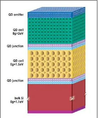
21 In order to gain a deeper insight in the issue of solar cells efficiency improvement, we have to look back at Eq. (1.13) and Eq. (1.18) and try to be more quantitative. Schockley and Queisser calculated that an ideal single junction solar cell with maximum QE and light trapping factor B, made up of materials with 1 eV < Eg < 1.6 eV (crystalline silicon and gallium arsenide), has an efficiency of 33%. This value could be, in principle, increased up to 40% restricting the emission angle ΩE to ΩS. Hence, in general, the biggest efficiency loss is owing to thermalization of hot photo-generated pairs and lack of sub-gap photons absorption. To partially unlock such a big conversion efficiency potential it is necessary to fabricate a solar cell with an overall decreasing graded band gap. In this way, the high Eg front of the device, facing as first the incoming radiation, will absorb only the photons whose energy is very similar to the high Eg (blue-green light). The generated pairs, in turn, will occupy energy states essentially adjacent to bands edges, thus they cannot thermalize. The lower energy light (yellow-red-NIR) entirely transmitted through the first cell layer will be then absorbed by the next layer whose band gap is now well matched with the incoming light. Again the generated pairs will not have the possibility to thermalize. It has been theoretically and experimentally proven that the "tandem-cell", shown in Fig. 1.5, fulfill this aim, increasing the efficiency up to 40% (double junction cell) or even 60% (six junctions cell).
22 A less efficient alternative to this solution is the utilization of solar cells containing materials absorbing sub-gap photons (up-converters or intermediate band layers) or "splitting" an high energetic photon (UV-blue-green) in many lower energy photons, better matched with the device band gap (down-converter). Most of these kind of innovative cells exist only as proof of concept devices, while the most successful tandem cells, in spite of showing astonishing performances in laboratories, are still far from wide spread deployment in PV global market.
In order to spread PV energy supply on large scales it is, however, important and urgent to decrease the price of solar cells, using a smaller amount of precious material, as crystalline silicon. As regards c-Si cells, advances in smarter fabrication steps (casting, cutting, etc...) recently heavily decreased solar module prices. Nevertheless, utilization of novel materials as thin films (less than 100 nm) is envisaged as a promising alternative. Some of these materials have direct band gaps, thus higher absorption coefficient and QE compared to crystalline silicon. The former property allows the use of much thinner absorber layers without significant absorption losses. Unfortunately, the set of alloys with the best (for now) recorded performances embraces materials, as CIGS (copper-indium-gallium-sulfur) and CdTe (cadmium telluride), containing rare or toxic elements. Therefore developing non-toxic and Earth-abundant material based cells is a compelling aim for applied physics research. Among the wide ensemble of novel candidates (organic compounds, perovskites, oxides, etc...), metal oxides, such as cuprous oxide (Cu2O), are of paramount interest.
Apart from the above mentioned innovative materials, crystalline silicon, micro-crystalline silicon (μc-Si) and hydrogenated amorphous silicon (α-Si:H) based cells could also have great efficiencies (for example c-Si cells could reach 40%) if light trapping and management inside the devices are successfully accomplished.
To sum up, there are three possible strategies to achieve super high efficiency cells and/or extremely cheap (with efficiencies bigger than 10%) solar cells:
1. Enhance c-Si, μc-Si and α-Si:H based cells efficiencies by means of innovative and yet not fully explored light-matter interactions, which can allow to better engineer the flow of light inside the solar cell.
2. To develop and to improve cheap thin-film solar cells employing high performances non-toxic and abundant materials. Junctions based on these materials can be integrated in multi-junctions cells if the absorber band gap of the former junction does not match the solar spectrum.
3. To fabricate and to improve multi-junction (tandem) solar cells, which are expensive but ultra efficient. The costs can be constrained to reasonable values exploiting solar irradiation concentration on small area devices.
23
1.6 - Outline of the work
Taking inspiration from the issues discussed in the points 1. and 2., with the research activity carried out during my Ph.D. studies, I provided the following contributes:
1. Research and development of a simple synthesis of semiconductor nano-structures, with proper morphologies and shapes to provide efficient radiation harvesting for solar cells. Moreover, it has been undertaken an examination of novel nano-structures geometries and the related light-matter interactions. 2. Investigation of some key features of physical and chemical deposition
methods, suitable for the synthesis of cuprous oxide thin films for cheap and green solar cells. Since the efficiency of Cu2O based hetero-junctions has not
yet surpassed 6% [9], it has been also endeavored to improve the material properties by means of doping with a wide variety of non-toxic and Earth-abundant elements. In particular, the doping has been fulfilled employing deeply different approaches.
The first subject is discussed in chapter 2. Firstly it is provided a review on the light trapping principles and approaches, unfold and employed since the beginning of the PV era (sections 2.1, 2.2 and 2.3). After a brief overview on the most promising nano-structures scalable fabrication techniques (section 2.4), it is reported my experimental activity aimed at seeking and describing efficient light scattering and trapping in silicon nano-wires (section 2.5) and novel interconnected silicon nano-structures (section 2.8), respectively fabricated by catalyzed CVD and pulsed laser induced dewetting. The nano-structures synthesis by pulsed laser irradiation, the related characterizations and the investigation on the silicon NWs optical properties was performed at the MATIS - IMM laboratories of the University of Catania (Italy).
The topic of chapter 3 is Cu2O thin films for photovoltaic applications. The first section
reports the state of the art of Cu2O-based cells and the issues concerning the
drawbacks and their possible solutions. Section 3.2 is an overview on the structural, optical and electrical properties of the bulk material. The summary of the principal methods for the deposition of thin films and their properties is presented in section 3.3. Section 3.4 deals with the various effects that doping can have on the material characteristics. The second part of the chapter presents the experimental results. Specifically, one physical deposition method, RF magnetron sputtering (section 3.5), has been compared with one chemical technique, spray pyrolysis (section 3.7), providing the key features of both the synthesis methods.
24 Moreover, two deeply different doping techniques are investigated:
1. out -of-equilibrium incorporation of nitrogen atoms in sputtered films by ion implantation (section 3.6);
2. Zn, Mg and Ca doping, carried out during the spray pyrolysis film growth (section 3.8).
Furthermore, the variety of dopants permitted to examine various aspects of the doping effects on the Cu2O physical properties, encompassing structural, optical and
electrical modulation.
The synthesis of Cu2O thin films by RF magnetron sputtering, nitrogen doping by ion
implantation and all the related characterizations, were performed at the MATIS - IMM laboratories of the University of Catania (Italy).
The deposition of Cu2O samples by ultra-sonic spray pyrolysis, Zn, Mg and Ca doping
with the relative analyses were carried out during the eight months richly spent at the laboratories of CENIMAT and of the "Departamento de Ciencias e Tecnologia dos Materiais" at the Nova University of Lisbon (Portugal).
25
Bibliography
[1] Energy for a Suitable World: From the Oil Age to a Sun-Powered Future - N. Armaroli; V. Balzani - Wiley-VCH (2011)
[2] Fundamentals of Materials for Energy and Environmental Sustainability - Edited by D. S. Ginley & D. Cahen - Cambridge University Press (2012)
[3] Key World Energy Statistics - International Energy Agency (2013) [4] Link; La Nuova Scienza delle Reti - A. L. Barabasi - Einaudi (2008)
[5] Dispositivi a Semiconduttore; Comportamento Fisico e Tecnologico - S. M. Sze - Hoepli (1991)
[6] Physics of Solar Cells; From Principles to New Concepts - P. Würfel - Wiley (2005). [7] A. Polman; H. A. Atwater - Nature Materials; Vol. 11 (2012).
[8] ARC Photovoltaics Centre of Excellence - Annual Report (2009)
26
2 - LIGHT TRAPPING FOR PHOTOVOLTAICS
2.1 - Antireflection coatings
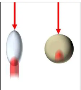
In section 1.5 it has been stated that, in a solar cell, non-efficient light trapping causes a reduction of the short-circuit current Jsc and a decrease of the open circuit voltage Voc, leading to an overall shrinkage of the cell efficiency. Non-efficient light trapping occurs in the cell, when some photons with energy above the material optical band gap Eg, are lost before their absorption in the active layer of the device. For example, since at the air/cell interface there is an index of refraction discontinuity, a fraction of this incoming photons is reflected back to the air (see Fig. 2.1). Moreover photons with energy slightly higher than Eg, transmitted through the air/cell interface, can escape from the cell front or from the back surface of the cell if its thickness is not sufficient to ensure a high absorption probability. In fact, when the cell thickness is comparable or less than the penetration depth 1/α, being α(ћω) the absorption coefficient, the absorption probability for a straight crossing photon is smaller than 40%.
The photon density of states (PDOS) in a medium is proportional to square of the refraction index n2 [1], thus, for a certain photon energy ћω, the materials of a cell can accommodate more photon modes compared to the air, which has always a smaller n. Consequently, all possible incident photons (coming from the hemispherical solid angle 2π) can cross the cell surface to occupy one of the material photon states, without violating the Second Principle of Thermodynamics [2]. This fact makes suppression of surface reflection theoretically possible by means of proper refraction index tuning of the cell front material. Indeed one of the earliest light trapping approaches is the growth of antireflection coatings (ARCs) on the cells surface. Such approach is based on the ray-optics interference effects caused by the interaction of light with a stack of layers coating the cell surface.
27 Considering unpolarized light (as sunlight is) normally incident on a single ARC layer with thickness d1 = λ0/(4∙n1) (where λ0 is the light wavelength and n1 the refraction index of the layer) the light reflected from the coating/cell interface will go back to the air with a phase change of π. In this way, the ray will undergo destructive interference with the incident ray and the total reflection coefficient of the coated cell surface will be [3]:
(2.1)
which is null for:
(2.2)
Unfortunately, ARC layers thickness is optimized only for one wavelength λ0. Since the sun spectrum is broad, it has to be considered, as reported in Eq. (2.3), R(λ) averaged on the sun wavelength range. Moreover such average calculation has to take into account the spectral response of the cell S(λ).
(2.3) The optimum design of an antireflection stack coating is numerically calculated by searching a minimum for [3].
Antireflection coatings enhance the light transmitted through the air/cell front interface, but do not change the rays path inside the cell, thus do not solve the problem of the large loss of those photons whose energy is just above Eg. To overcome this drawback, it is necessary to redesign the (coated) cell surface into a more complex morphology, in order to exploit those light diffusion and scattering mechanisms which enhance the rays path inside the cell.
28
2.2 - Light trapping by surface texturing in the ray-optics regime
Consider a slab of transparent (low α) material placed in a region filled of black-body radiation. If this slab is in equilibrium with the external radiation the internal electro-magnetic energy intensity is [1]:
(2.4)
where c0 is the light speed in vacuum, n is the refractive index of the slab material and ћω is the photon energy. This expression differs from the external energy intensity Ibb by the factor n2. Therefore it can be stated that [1]:
(2.5)
Since the slab is transparent Eq. (2.5) holds separately for every frequency ω.
If the external radiation has not the isotropic distribution of the black-body, the behaviour of the internal light may not be ergodic, hence Eq. (2.5) is not valid. For example, in a planar slab the refracted photons keep memory of the incident angle (by means of the Snell's Law) and Eq. (2.5) breaks down. Nevertheless, if the surface of the slab is textured in such a way that the collimated incident rays, undergoing random refractions and total reflections, are able to lose any correlation with the incidence angle, the internal radiation distribution will be isotropic. When a textured surface has this kind of geometry, it is defined as an ergodic surface and Eq. (2.5) is correct.
Some random textures, as resulting from proper chemical etching or lithographic patterning, could approach this ideal property. Even slabs with ordered surface textures can show this characteristic, because light randomization can occur on successive internal reflections and can result from the spatial average over the illuminated area [1].
In conclusion, if the morphology of the textured slab surface ensures light ergodic behaviour inside the material, Eq. (2.6) holds also for collimated incident light. In particular, if the back surface is covered with a perfectly reflecting film, the external radiation will be confined only on one half of the region. This leads to a concentration factor of 2, thus [1]:
29 Eq. (2.6) is valid if the wave optical effects can be ignored, that is, if the slab thickness is higher than λ/2n.
If now we consider that the photons, isotropically distributed (over 4π) inside the slab, can be absorbed (the relative absorption coefficient should be low if the previous results has to be still valid and this is true for photons whose energy is slightly above
Eg), the current of the absorbed photons in the volume V = s∙L is [2]:
(2.7)
where α is the absorption coefficient, s is the area on the surface, L is the ray internal path length and IΩ is the photon current inside the slab per solid angle. For Eq. (2.7) it has been assumed a surface reflection equal to zero.
According to Eq. (2.6), the photon current per solid angle outside (where photons are distributed over 2π) is a factor of 2n2 lower, therefore, the escaping photons current is [2]:
(2.8)
At equilibrium it should be:
(2.9) Absorptivity is defined as [2]: (2.10)
The last approximated equality is acceptable because α is assumed low. The absorptivity for a single photon passing along L, in non-textured slab, is α∙L. Thus, Eq. (2.10) states that the absorptivity of a cell, with ergodic surface, is enhanced by a factor of 4n2, defined as the "Yablonovitch limit" [4]. Such enhancement results from the light trapping effects of the peculiar surface morphology. If the surface texturing only partially causes the randomization of light inside the cell, the absorptivity enhancement factor is less than the Yablonovitch limit. For this not perfectly ergodic cell surfaces a "trapping factor" I is defined, always ranging from unity (in the case of planar slabs) to 4n2.
30 According to Eq. (2.10), the factor B becomes I/4n2 in Eq. (1.13) [5], which can be rewritten in the following way:
(2.11)
Combining wisely the antireflection and light trapping principles, discussed in these two sections, it is possible to improve the open circuit voltage and to increase the photo-current of a cell, in other words its efficiency. In addition, decreasing the efficiency loss factor K∙T0∙ln(4n2/I) in Eq. (2.11) by improved light trapping, allows to obtain high efficiency solar cells even with lower materials quality, i.e. lower QE. This could reduce the cost of c-Si based cells. The group led by Professor M. Green, implementing optimized antireflection coatings and efficient light trapping surface textures (inverted pyramids), fabricated a c-Si solar cell (PERL) with the high efficiency of 25% (see Fig. 2.1) [6].
Proficient light trapping is mandatory to fabricate high efficiency thin-film solar cells, because the reduced thickness of the absorber layer does not allow great absorption of those photons with energy slightly above the material band gap. However, all the principles and the results discussed up to now are valid in the ray-optics regime, that is, when the thickness of the cell and the size of the texture features are much greater than the wavelength of the light. For light trapping in thin-film cells, it is necessary to work in the wave regime, where light is indeed treated as a wave phenomenon, therefore it can be made to interfere in specific regions of the cell [4].
As it will be shown in the next sections, this new light management approach is essentially based on the redistribution of the PDOS inside the cell. Whereas, in the ray-optics regime, PDOS are absolutely not redistributed in space and spectrum.
31
2.3 -Light trapping approaches for thin-film solar cells
Light trapping and management in thin-film solar cells can be accomplished employing dielectric or metallic structures in the cells. In fact, these objects, that can be particles, gratings or multilayer with nano or mesoscopic dimensions, interact with the incident light causing radiation scattering, diffraction, interference and concentration phenomena inside the cell. Appropriate engineering of these objects structural parameters, which control the light-matter interactions, together with a suitable choice of structure disposition in the solar cell, are necessary actions to obtain excellent cell performances in terms of solar radiation harvesting.
Dielectric ordered structures, for cell light management, form the large family of photonic crystals (PC). PCs can be categorized in three classes, 1D, 2D and 3D, according to the dimensions along which the dielectric constant ε periodicity occurs. A PC can be a periodic stack of alternating dielectric layers with different dielectric constants (1D), an array of dielectric rods (2D) or a lattice of dielectric particle (3D), such as spheres (see Fig. 2.2). The symmetry arguments that can be carried out in these structures resemble the theory of electronic states in crystal lattices, therefore, PC can also possess a range of frequencies in which light cannot propagate in the structure, known as photonic band gap (PBG) [7]. Owing to this property, PCs can be used as non-absorbing back reflectors in solar cells [4].
32 A PC can be designed also as a Bragg grating (see Fig. 2.3), diffracting, in reflection or transmission, (normal) incident light according to the well known Bragg formula: (2.12) where d is the grating period, m is the diffraction order integer and θm is the scattering angle (of order m) with respect to the normal direction, at which the light is diffracted. The diffracted light is the sum of the waves coherently diffracted from each of the grating elements. The total pattern is a convolution of diffraction and interference patterns, therefore the intensity of the different orders is a decreasing function of index m. When a PC grating is combined with a thin absorbing layer, the light, scattered at angles that ensure total internal reflection, is coupled with the quasi-guided modes of the layer (see Fig. 2.3). This means that the diffracted light is trapped inside the layer and will propagate, almost in two dimensions, on enhanced paths, having, in this way, more probability to be absorbed.
Fig. 2.3 Dielectric diffraction grating on the back of a solar cell. The incident (full line) light is scattered (dotted line) and coupled with quasi guided modes.
33 The physics underneath PC Bragg gratings, unfortunately, entails some shortcomings for light trapping and absorption amplification [4] [8]:
1. Eq. (2.12) depends on the wavelength λ;
2. gratings with large period, in spite of exciting many resonances, scatter low order resonances at small angles, thus total internal reflection and coupling with quasi-guided modes do not occur;
3. small period gratings scatter fewer (yet stronger) resonances;
4. low order diffractions, which according to point 2. are not so efficiently trapped, are the most intense for a single grating.
Recently, it has been theoretically and experimentally proven by Professor M. Krauss and co-workers that the "super-cell" design approach can overcome the problems listed above [8]. The concept of "super-cell" is based on the argument that the diffraction pattern of a single grating, in which the low order resonances are the most intense, can be properly modulated by means of interference effects. In fact, a "super-cell" grating, resulting from the superposition of sub-gratings, spatially shifted from one another, can design destructive interference for the lower order diffractions and constructive interference for the higher ones (see Fig. 2.4). Destructive interference occurs because the low order diffractions from every sub-grating, result out of phase with one another (see Fig. 2.4).
Fig. 2.4 The super-cell grating as superposition of sub-gratings. The total diffraction pattern is the result of interference between the sub-gratings patterns.
![Fig. 2.1 PERL solar cell (image taken from Ref. [6]).](https://thumb-eu.123doks.com/thumbv2/123dokorg/4520831.34908/40.773.184.614.427.650/fig-perl-solar-cell-image-taken-ref.webp)