UNIVERSITY
OF TRENTO
DEPARTMENT OF INFORMATION AND COMMUNICATION TECHNOLOGY
38050 Povo – Trento (Italy), Via Sommarive 14 http://www.dit.unitn.it
A
V
ERSATILEE
NHANCEDG
ENETICA
LGORITHM FORP
LANARA
RRAYD
ESIGNMassimo Donelli, Salvatore Caorsi, Francesco De Natale, Davide
Franceschini, and Andrea Massa
August 2004
A Versatile Enhanced Genetic Algorithm for Planar Array Design
Massimo Donelli*, Salvatore Caorsi**, Francesco De Natale*, Davide Franceschini*, and Andrea Massa*
Department of Information and Communication Technology University of Trento Via Sommarive, 14 38050 Trento, ITALY E-mail: [email protected] Department of Electronics University of Pavia Via Ferrata, 1 27100 Pavia, ITALY
2
A Versatile Enhanced Genetic Algorithm for Planar Array Design
Massimo Donelli, Salvatore Caorsi, Francesco De Natale, Davide Franceschini, and Andrea Massa
Indexing terms: Planar array, Antenna Array Synthesis, Genetic Algorithms.
Abstract - In order to synthesize planar, sparse, and aperiodic arrays, a numerical procedure based on an enhanced genetic algorithm is proposed. The method maximizes a suitably defined single-objective fitness function iteratively acting on the states and the weights of the elements of the array. Such a cost function is related to the shape of the desired beam pattern, to the number of active elements and to others user-defined array-pattern constraints. To preliminarily assess the effectiveness of the approach, selected numerical experiments are performed. The obtained results seem to confirm its feasibility. Moreover, given the heterogeneity of the test benchmarks, the versatility is pointed out as a key-feature of the implemented methodology.
3
I. INTRODUCTION
The synthesis of the beam pattern of two-dimensional arrays is aimed at defining the optimal configuration of positions and weights of the array elements to fulfill several user-defined constraints (e.g., the reduction of the side-lobes peak (SLP) under a fixed threshold, a narrow main lobe, a reduced number of array elements, a small dimension of the array, etc…). An analytical solution to such a problem is not available and numerical techniques are generally used. In [1] a method based on the linear-programming theory has been applied to reduce the level of the side-lobes of a thinned array when the number of elements and the main-lobe width are fixed. Such an approach turned out to be computationally expensive in dealing with large arrays because of an excessive increase in the memory requirement and computational load. To overcome this drawback, a simulated annealing (SA) procedure has been proposed in [2] and applied to synthesize a 20×10 weighted array.
However, since single-agent global optimization procedures are characterized by a reduced convergence rate, improved and more effective (in terms of convergence rate of the iterative process) methodologies are required.
In such a framework, this paper presents a multiple-agent optimization technique aimed at fully exploiting the key-features of genetic-based methodologies (GA) [3] in dealing with two-dimensional arrays [4]. The computational efficiency of the presented method has been improved with a suitably defined hybridization and through the definition of a gradient-based optimizer. It should be pointed out that it is out of the main scopeof such a research work to focus on the algorithmic issues (hybrid codings and gradient-based optimizers are commonplace in GA usage). Nevertheless, these aspects are deeply investigated in order to define a versatile approach, being able to successfully deal with a large class of planar structures and synthesis problems with various constraints (avoiding the customization of the method to a single kind of two-dimensional arrays).
The manuscript is organized as follows. In Section II, the mathematical formulation of the approach is presented. To assess the feasibility and the versatility of the approach, Section III shows the results of selected/representative numerical experiments. Finally, some conclusions and guidelines for future developments are drawn (Sect. IV).
II. SYNTHESIS PROCEDURE –MATHEMATICAL FORMULATION
Generally speaking, the problem of the synthesis of a two-dimensional array is characterized by different and conflicting requirements to be satisfied. It is an example of a
4
multi-objective problem. Unlike the strategy described in [5], the proposed approach does not consider a multi-objective optimization but it aims at reducing the multi-objective problem into a classical single-objective one through an ad-hoc combination of several terms related to the physical parameters of the array.
Let us consider a typical set of requirements to be satisfied:
• Minimum discrepancy between the synthesized and a reference beam pattern, pd
( )
u, ; v • Narrow main lobe;• Low level of the side-lobes; • Uniform level of the side-lobes;
• Reduced number of active array elements, N . a
The single-objective function is defined as a linear combination of these constraints
( )
( )
( )
( )
W X W X W X W X , , , 1 , 4 3 SLP SLL a 2 BP 1f kN k f k f k f + + + = (1)where the unknown parameters to be optimized are the states X=[x1,...,xN] and the weights ]
,..., [w1 wN =
W of the array elements, which are assumed to be located in N positions of an
2
λ equally spaced two-dimensional grid (λ being the free-space wavelength). The terms of the cost function are defined as follows
(
X W)
(
p u,v p u,v)
dudv fBP , ( ) d( ) S v) (u,∫∫
∈ − =(
,)
max{
( )}
11 v u, p f v R u R SLP ≤ ≤ ≤ ≤ = W X(
,)
{
( )}
{
( )}
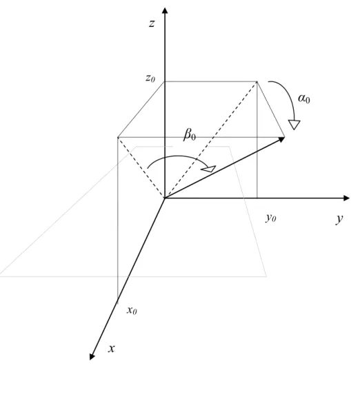
11 11 v u, p av v u, p max f v R u R v R u R SLL ≤ ≤ ≤ ≤ ≤ ≤ ≤ ≤ − = W Xwhere u = sinα - sinα0 and v = sinβ - sinβ0 take into account the direction of arrival of the
impinging signal (defined by the angular coordinates (α,β)), and the steering direction ∆0 =
(α0,β0) (Fig. 1). R is a real value allowing the main lobe to be excluded from the calculation
of the side-lobes level and S defines the range for which p
( )
u,v > pd( )
u,v , p(u,v) being the normalized beam pattern; k1, k2, k3 and k4 are normalizing coefficients, chosen empirically.5
The solution of the arising problem is obtained through the maximization of (1). Towards this end, an enhanced GA (EGA) has been used. GAs are optimization algorithms based on the Darwinian theory of evolution [6]. Standard GAs [7], [8] consider a population of P trial solutions coded in binary strings called chromosomes and ranked according to the value of a suitable objective function (called fitness function). The best solutions are selected and undergo crossover and mutation operators to generate a new population. The iterative procedure is stopped when a fixed threshold for the fitness function ( f ≤ηEGA) or a maximum number of generations has been reached (i=IEGA, i being the iteration number).
In the following, the most relevant features (compared to standard implementations) of the enhanced GA-based procedure will be detailed.
A. CHROMOSOME REPRESENTATION
To accurately represent the unknown parameters, a hybrid coding has been used. The states and the weights of the array elements have been represented with boolean and real parameters, respectively. The chromosome Φ is a hybrid-coded string
{
} {
}
{ }
0,1{
min, max}
2 ,..., 1 ; ,..., 1 , ; ,..., 1 , W W w x N m N n w N n x n n m n n ∈ = = Φ = = = = Φ (2)where Wmin and Wmax define the range of variation of the weight coefficients.
B. GENETIC OPERATORS
Concerning the genetic operators, because of the chromosome representation, a suitable mixed real-boolean crossover [9] has been defined. Two selected (according to a roulette wheel schema [10]) chromosomes, Φ and (1) Φ , are superimposed and different crossover (2)
rules are used according to the gene under test. If Φm =wn, then
[ ]
(
)
[ ]
(2) ' (2)(
)
(1) ) 2 ( ) 1 ( ' ) 1 ( 1 1 m m m m m m r r r r Φ − + Φ = Φ Φ − + Φ = Φ (3)r being a random value between 0 and 1. If Φm =xn, the state of the n-th sensor is maintained. Otherwise, the state of the sensor is chosen randomly.
6
The mutation operates with different elements’ death and birth probabilities (p and d
b
p , respectively) and performs a random perturbation of the weight coefficients in the range
{
Wmin,Wmax}
. The mutation and the crossover operators are applied with a probability p mand p , respectively. c
In order to increase the convergence rate of the iterative process, a gradient-search operator is defined. It is applied when a fixed threshold for the cost function has been achieved ( f
( )
Φi ≤ηOCG,(
( )
)
⎭ ⎬ ⎫ ⎩ ⎨ ⎧ ⎥⎦ ⎤ ⎢⎣ ⎡ Φ = Φ = = ) ( ,..., 1 ,.., 1 min min arg p P p i ji f ). The sensor states are frozen and
the weight coefficients are modified to optimize the beam pattern shape. More in detail, starting from the optimal trial solution reached until now, Φi,k =Φi, k =0, the following steps are iteratively performed:
(a). fSLP
( )
Φi,k and fSLL( )
Φi,k are evaluated;(b). If fSLP
( )
Φi,k >ηSLP then Φi,k+1=Φi,k +αkdk where α is chosen according to the kstandard Polak-Ribière conjugate-gradient method [11] being
[ ]
[
( )
]
[ ]
⎩ ⎨ ⎧−∇ Φ ∈ = otherwise 0 , 1 if , m N f d SLP ik m m k . (4)Otherwise, the trial solution is updated by considering a new search direction given by
[ ]
[
( )
]
[ ]
⎩ ⎨ ⎧−∇ Φ ∈ = otherwise 0 , 1 if , m N f d SLL ik m m k . (5)(c). If k =Kmax or a fixed threshold for the SLP has been attained ( fSLP
( )
Φi,k ≤ηconv), then the iterative procedure stops and the best achieved trial solution is assumed as the final parametric description of the synthesized array.A flowchart of the EGA-based procedure is shown in Figure 2.
III. NUMERICAL RESULTS
To assess the effectiveness and the versatility of the proposed array synthesis method, a large number of numerical tests, related to different array geometries and various constraints, has been performed. Moreover, some reference test cases have been considered and the obtained results are compared with those reported in the related literature.
In order to give some quantitative information on the method performance, let us define a set of representative quantities. Concerning the geometric dimension of the array, let us
7
indicate as occupation domain D, the minimum square area where the array elements lie. Moreover, let us define the array sparseness coefficient (hereinafter indicated with ρ ) equal S to the ratio between the occupation domain and the normalized number of active array elements to quantify the allocation density of the array elements
2 2⎟⎠ ⎞ ⎜ ⎝ ⎛ ⎟ ⎠ ⎞ ⎜ ⎝ ⎛ = λ ρ a S N N D (6) a
N being the number of active array elements.
The first numerical experiment deals with the test case considered in [1], [2] and it is related to a 12× planar array. The values of the EGA parameters, chosen according to the 12 guidelines in [8], are: P = 160, IEGA =400, 75pc =0. (crossover probability), and ξM = 0.01 (mutation probability). Moreover, after an exhaustive calibration process, the values of the thresholds turned out to be: ηOCG =0.1, ηconv =0.0001, and ηEGA=0.01. As far as the fitness
coefficients are concerned, the following values (heuristically-defined) have been considered:
12 . 0
1=
k , k2 =0.12, 1k3 =0. , and k4 =4.
Figure 3 shows the beam pattern of the synthesized array (owing to the symmetry properties of p(u,v), only the values in the range u ∈ [-1,1] and v ∈ [0,1] are shown). The array is made up of Na =64 active elements. The peak of the side-lobes level turns out to be equal to – 24.56 dB and the main lobe width (ML) is u-6dB = v-6dB = 0.327. These values indicate that
such a solution is closer to the optimal one [1] than that shown in [2]. In [2] the same main lobe width has been achieved but with a larger number of array elements (Na =67) and a higher side-lobes level (SLP=−24.3dB). Moreover, the EGA-based procedure allows a reduction in the value of the sparseness coefficient as a consequence of the accumulation of the array elements shown in Fig. 4. ρ is equal to 40 while the arrays synthesized in [1] and S [2] are characterized by ρS =62 and ρS =61.4, respectively. In particular, the relevance of
such a result is further confirmed by the random arrays theory, which estimates an average side-lobe level equal to – 18 dB for a 64 random-placed element array [12].
Because of the statistical nature of the optimization approach, each test case has been solved by running several times the EGA-based procedure to assess its reliability. As confirmed from the statistics reported in Tab. I, the approach shows a good stability. The average values of the
8
characteristic parameters are very close to those of the optimal array with small standard deviations.
Finally, Fig. 5 shows the behavior of the peak of the side-lobes level versus the number of active elements. For completeness, the difference between the beam pattern of a Na =62 active elements (ML=0.34 and SLP=−24.40dB) and the optimal array is given in Fig. 6, thus evidencing an increase in the main lobe width(ML=0.34 versus ML=0.327).
Concerning the second test case, it deals with the optimization of a N =20×10 array [13]. The synthesis process is aimed at achieving a fixed level of the side-lobes (−20dB) along the axes u = 0 (SLP ) and v = 0 (v SLP ), by minimizing the number of active array u elements. The EGA method is able to synthesize a thinned array of Na =79 active elements with the following beam-pattern characteristics: SLPu =−22.9dB, SLPv =−20.1dB,
123 . 0
6 =
− dB
u , 276v− dB6 =0. . The array sparseness coefficient is equal to 79, which positively compares with that obtained in [13] (ρS =108).
To confirm the versatility of the approach, let us consider the reduction of the side-lobes level by preserving the main-lobe width as well. The EGA succeeds in synthesizing a Na =90 -element array with a reduction of the SLP of about 3.50dB (ρS =90). Such a result clearly points out the flexibility of the proposed method in successfully handling the trade-off between the side-lobe peak and the number of active elements. Tab. II summarizes the beam pattern characteristics of the synthesized arrays and Figs. 7-8 show the beam pattern behavior on the reference axes and the array layouts, respectively. For completeness, to give an idea of the reproducibility of the synthesis results, a statistical evaluation of the configurations obtained after many EGA executions is provided in Tab. I.
IV. CONCLUSIONS
A versatile method for the synthesis of sparse planar arrays has been proposed. The method allows the specification of multiple constraints related to the main beam width, the side-lobes level, the location and the number of active array elements. Towards this purpose, the original multiple-objective problem has been recast in the optimization of a single-objective cost function. Such a maximization has been carried out by iteratively thinning and weighting the array elements with a synthesis strategy defined by an enhanced hybrid-coded genetic algorithm. The effectiveness, reliability and flexibility of the approach have been
9
assessed through selected test cases. The obtained results are favorably compared with those reported in the related literature and achieved employing deterministic and/or stochastic methodologies. Moreover, thanks to the introduction of the hybridization and of the gradient-based optimizer, the EGA-gradient-based procedure allows a reduction of about 15% in terms of required execution time.
Future developments will be aimed at dealing with other geometries and constraints as well as at considering a time-varying environment where various interferences occur. Such a situation generally appears in real communications and requires a feasible and versatile procedure, being able to perform a real-time array synthesis by adaptively tuning antenna characteristics and parameters. Because of the versatility of the EGA, it seems a good candidate to face this problem.
10
REFERENCES
[1] S. Holm, B. Elgetun, G. Dahl, “Properties of the beampattern of weight- and layout-optimized sparse arrays,” IEEE Trans. Ultrasonics, Ferroelectrics, and Frequency Control, vol. 44, pp 983-991, 1997.
[2] A. Trucco, “Thinning and weighting of large planar arrays by simulated annealing,” IEEE Trans. Ultrasonics, Ferroelectrics, and Frequency Control, vol. 46, pp. 347-355, 1999.
[3] D. E. Goldberg, Genetic Algorithms in Search, Optimization and Machine Learning. Addison-Wesley, Reading, MA, 1989.
[4] F. Ares-Pena, “Application of genetic algorithms and simulated annealing to some antenna problems,” in Electromagnetic Optimization by Genetic Algorithms, eds. Y. Rahmat-Samii and E. Michielssen, Wiley & Sons, pp. 119-154, 1999.
[5] D. S. Weile and E. Michielssen, “Integer-coded pareto genetic algorithm design of constrained antenna arrays,” Electronic Lett., vol. 32, pp. 1744-1745, 1996.
[6] J. H. Holland. Adaptation in Natural and Artificial Systems. University of Michigan Press, Ann Arbor, 1975.
[7] D. S. Weile and E. Michielssen, “Genetic algorithm optimization applied to electromagnetics: A review,” IEEE Trans. Antennas Propagat., vol. 45, pp. 343-353, 1997.
[8] Y. Rahmat-Samii and E. Michielssen, Electromagnetic Optimization by Genetic Algorithms. Wiley & Sons, New York, 1999.
[9] S. Caorsi, A. Massa, and M. Pastorino, “A computational technique based on a real-coded genetic algorithm for microwave imaging purposes,” IEEE Trans. Geoscience and Remote Sensing, vol. 38, pp. 1697-1708, 2000.
[10] L. Davis, Handbook of Genetic Algorithms. Van Nostrand Reinhold, 1991. [11] E. Polak, Computational Methods. Academic Press, New York, 1971.
[12] Steinberg, Principles of Aperture and Array System Design. New York: Wiley, 1976.
[13] R. L. Haupt, “Thinned arrays using genetic algorithms,” IEEE Trans. Geoscience Antennas Propagat., vol. 42, pp. 993-999, 1994.
11
FIGURE CAPTIONS
• Figure 1. Planar array geometry and notations.
• Figure 2. Flowchart of the Enhanced Genetic Algorithm procedure (EGA)
• Figure 3. N =12×12-element planar array. Beam pattern of the Na =64-element synthesized array (SLP=−24.56dB, 327u−6dB =v−6dB =0. ).
• Figure 4. N =12×12-element planar array. Array layouts defined with (a) linear programming method [1] (ρS =62), (b) simulated annealing approach [2] (ρS =61.4),
and (c) EGA-based method (ρS =40).
• Figure 5. N =12×12-element planar array. EGA-based method. Side-lobe peak (SLP) as a function of the number of active array elements (N ) for several optimized arrays. a • Figure 6. N =12×12-element planar array. EGA-based method. Difference between
the beam pattern of the Na =62-element array (u-6dB = 0.340) and of the Na =64
-element array (u-6dB = 0.327).
• Figure 7. N =20×10-element planar array. Beam power patterns along the u and v axes.
• Figure 8. N =20×10-element planar array. Array layouts defined with (a) GA-based method [13] (Na =108 , ρS =108), (b) EGA-based method (Na =79 , ρS =79), and
12
TABLE CAPTIONS
• Table I.
Statistics of the array parameters after many runs of the EGA-based procedure (the superscript * indicates the average value between u-6dB and v-6dB)
• Table II.
10 20× =
N -element planar array. Comparison between the array parameters of the solution obtained with the GA-based approach [13] and with the EGA-based method.
13
Fig. 1 – M. Donelli et al., “A Versatile Enhanced Genetic Algorithm for …”.
y
x
z
α
0β
0 x0 z0 y014
Fig. 2 – M. Donelli et al., “A Versatile Enhanced Genetic Algorithm for …”. i = i + 1 l = 1 OCG l i f(Φ )≤η ? p pc≥ ? Crossover Reproduction Mutation l = l + 1 yes yes START STOP no k = 0 i k =Φ Φ SLP k f(Φ )≤η ? Perform one GSSLP iteration
( )
k SLP k f d =−∇ Φ Perform one GSSLL iteration( )
k SLL k f d =−∇ Φ k = k+1 yes no i = IEGA ? yes Evaluate fitness ) ( li f Φ i = 1 P l < ? p pm ≥ ? EGA k f(Φ )≤η ? yes yes no yes no no no no15
16 0 2 4 6 0 2 4 6 x [lam da] y [ lam da ] 0 2 4 6 0 2 4 6 x [lam da] y [ lam da ] 0 2 4 6 0 2 4 6 x [lam da] y [ lam da ]
17 58 60 62 64 66 68 70 -30 -29 -28 -27 -26 -25 -24 -23
Number of active elements (Na)
SL
P [d
B]
Best EGA results EGA best compromise [2]
18
19 0 0.1 0.2 0.3 0.4 0.5 0.6 0.7 0.8 0.9 1 -40 -30 -20 -10 0 u beam power pattern [dB] 0 0.1 0.2 0.3 0.4 0.5 0.6 0.7 0.8 0.9 1 -40 -30 -20 -10 0 v beam pow er pattern [dB] EGA (a) EGA (b) [13]
20 0 2 4 6 8 10 0 1 2 3 4 5 x [lam da] y [ la m d a ] 0 2 4 6 8 10 0 1 2 3 4 5 x [lam da] y [ lam da ] 0 2 4 6 8 10 0 1 2 3 4 5 x [lam da] y [ lam da ]
21
Array Geometry Navg σN SLPavg σSLP MLW-6dB ρD,avg
12 × 12 weighted 65 1.71 - 24.32 2.19 0.334 (*) 42.50 20 × 10 83 4.21 - 20.01 (*) 0.65 (*) 0.202 (*) 84.20 20 × 10 weighted 101 2.48 - 19.82 0.37 0.214 (*) 93.60
22
Tab. II – M. Donelli et al., “A Versatile Enhanced Genetic Algorithm for …”.
Synthesis Method Na SLPu SLPv u-6dB v-6dB SLPu,v
Best in [13] 108 - 20.07 dB - 19.76 dB 0.123 0.281 - 14.31 dB Proposed Approach (a) 79 - 22.90 dB - 20.10 dB 0.123 0.276 - 11.00 dB Proposed Approach (b) 90 - 22.80 dB - 21.10 dB 0.123 0.276 - 14.50 dB