Alma Mater Studiorum
Alma Mater Studiorum –
– Università di Bologna
Università di Bologna
DOTTORATO DI RICERCA IN
CHIMICA
Ciclo XXVII
Settore Concorsuale di afferenza: 03/B2 Settore Scientifico disciplinare: CHIM-07
Patterning soft matter for cell culturing
Presentata da:
Silvia Tortorella
Coordinatore Dottorato
Relatore
Prof. Aldo Roda
Prof. Francesco Zerbetto
Correlatore
Prof. Fabio Biscarini
Esame finale anno 2015
Alla mia famiglia
Ad Alessandro
ABSTRACT
In the search to understand the interaction between cells and their underlying substrates, life sciences are beginning to incorporate micro and nano-‐technology based tools to probe, measure and improve cellular behavior. In this frame, patterned surfaces provide a platform for highly defined cellular interactions and, in perspective, they offer unique advantages for artificial implants. For these reasons, functionalized materials have recently become a central topic in tissue engineering.
Nanotechnology, with its rich toolbox of techniques, can be the leading actor in the materials patterning field. Laser assisted methods, conventional and un-‐conventional lithography and other patterning techniques, allow the fabrication of functional supports with tunable properties, either physically, or topographically and chemically. Among them, soft lithography provides an effective (and low cost) strategy for manufacturing micro and nanostructures.
The main focus of this work is the use of different fabrication approaches aiming at a precise control of cell behavior, adhesion, proliferation and differentiation, through chemically and spatially designed surfaces.
3 types of patterning techniques were combined with 3 types of cell lines. Each method has been characterized at the nanoscale before cell seeding.
The thesis is divided as herein indicated: Chapter 1 is an introduction on the state of the art of nanotechnology, patterning techniques and regenerative medicine, along with a brief reference of one of the guiding projects of my PhD (Implantable Organic Nano-‐ Electronics I-‐ONE). In Chapter 2 we collected all the functionalization, fabrication and characterization techniques learned and employed during the PhD period. Chapter 3 and Chapter 4 describe the main technique we have worked with for accurate and controlled molecule deposition on surfaces: Laser Assisted Bioprinting (LAB). A very exhaustive description is provided and also some very notable applications are shown. In Chapter 5 the use of Lithographically Controlled Wetting (LCW) for patterning functional molecules (β-‐cyclodextrins, ACyD) on a glass support with modified hydrophobicity rate is reported in comparison with other drug-‐delivery methods.
Chapter 6 reports the use of thiols for the modulation of the cell adhesion onto surfaces.
Using the electrochemical desorption of self-‐assembly monolayers (SAM) of thiols, is possible to fabricate a chemical gradient made of anti-‐fouling molecules that can affect cell adhesion and growth. Chapter 7 concerns a very recent study about the fabrication of biodegradable-‐biocompatible microfluidics for the delivery of small volumes of active molecules preceded by a very short glance on the use of Polyhydroxybutyrate (PHB), a biodegradable polymer, employed for cell adhesion and growth.
Finally, at the end of the thesis, the main conclusions of the entire work are reported.
Table of Contents
ABSTRACT
Chapter 1 -‐
State of the art
1.1 Nanotechnology 10
1.2 Micro-‐nanostructured functional surfaces 11 1.3 Regenerative medicine for neural cells 12 1.4 Implantable Organic Nano-‐Electronics: i-‐ONE project 14
Chapter 2 -‐
Experimental and Fabrication techniques
2.1 Fabrication and patterning techniques
2.1.1 Laser Assisted Bioprinting (LAB) 16 LAB applications 18 2.1.2 Soft Lithography 19 Lithographically Controlled Wetting (LCW) 20 Microcontact Printing (μCP) 21 Replica Molding (REM)
2.1.3 Electrochemical desorption of Self Assembled Monolayers 22
2.1.4 Nanografting 24
2.2 Characterization techniques 25 2.2.1 Scanning Electron Microscopy (SEM)
2.2.2 Atomic Force Microscopy (AFM) 30 AFM vs other microscopes 32
AFM Instrumentation 33
Imaging modes 34
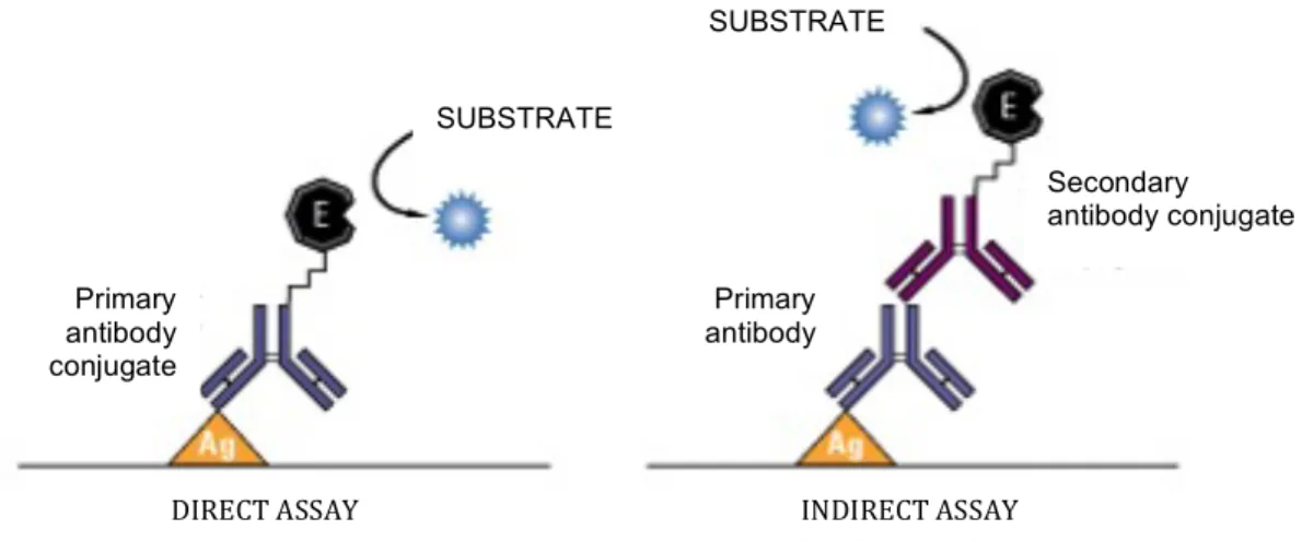
2.2.3 Fluorescence Microscopy 36 Immunofluorescence working principles 37
Actin Cytoskeleton and focal adhesion Staining
β-‐Tubulin III Antibody Staining 37
Patterning adhesion proteins with Laser Assisted Bioprinting
Chapter 3 -‐
Laser Assisted Bioprinting of Laminin on biodegradable PLGA substrates for stem cell adhesion and differentiation 443.1 Laminin functionalization of PLGA film 45 3.2 Adhesion of NE4C cells 50 3.3 Control and modulation of NE4C adhesion: cell adhesion mathematic
model 52
3.4 Differentiation of NE4C cells 59 3.5 Discussion and conclusions 62
Materials & Methods
Chapter 4 -‐
Laser Assisted Bioprinting of Laminin micrometric spots on cantilevers4.1 (Micro)cantilevers-‐based biosensors 72 4.2 Laser Assisted Bioprinting of Laminin on MCs 79 4.3 Frequency resonance analysis 81 4.4 Discussion and conclusions 83
Materials and Methods
Patterning chemical cues for cell positioning and migration
Chapter 5 -‐ Amphiphilic β-‐cyclodextrins (ACyDs) patterning
5.1 Introduction 89
5.2 β-‐Cyclodextrins (SC16NH2) surface patterning 90 5.3 SHSY5Y cells and SC16NH2 92 5.4 Discussion and conclusions 99
Chapter 6 -‐
Microcontact Printing (μCP) patterning and surface chemical gradient of anti-‐fouling thiols affect cell orientation, adhesion and growth6.1 Introduction 103
6.2 Microcontact Printing (μCP) of TOEG6 on gold
6.3 Chemical gradient of TOEG6 on gold 107 6.4 Discussion and conclusions 110
Material and methods
Chapter 7 –
Biodegradable and Biocompatible polymers for regenerative medicine applications7.1 Introduction 115
7.2 PHB (poly(3-‐hydroxybutyrate))
7.3 NPc and NE4C cells on PHB films 120 7.4 Microfluidics systems made of PLGA 122 7.5 NE4C cells adhesion gradient on PLGA microfluidics 123 7.6 Discussion and conclusions 125
Material and methods
CONCLUSIONS
List of Acronyms List of Publications
Acknowledgements
Chapter 1 – State of the art
In this chapter a brief introduction of the state of art of nanotechnology, surface functionalization and micro-‐nanopatterning is provided. A paragraph about regenerative medicine, with a particular focus on the thematic related to the regeneration of neural cells, is reported at the end of the chapter.
1.1 Nanotechnology
Nanotechnology is naturally very broad field, including different topics such as surface science, organic chemistry, molecular biology, semiconductor physics, microfabrication, etc. The related research and applications are equally different, ranging from the extension of conventional device physics to completely new approaches based on molecular self-‐assembly, from developing new materials with nanoscale dimensions to the direct control of matter on the atomic scale.
As defined by Saini et al [1], nanotechnology can be defined as the science and engineering involved in the design, synthesis, characterization, and application of materials and devices whose smallest functional organization, in at least one dimension, is on the nanometer scale. At these scales, is very important to considerate individual molecules and interacting groups in relation to the bulk macroscopic properties of the material or device, as it has a control over the fundamental molecular structure, which allows control over the macroscopic chemical and physical properties.
Scientists currently debate the future implications of nanotechnology. Nanotechnology may be able to create new materials and devices with a vast range of applications, such as in medicine, electronics, biomaterials and energy production. On the other hand, nanotechnology raises many of the issues already experienced by many novel technologies such as concerns about the toxicity and environmental impact of nanomaterials, and their potential effects on global economics, as well as speculation about various doomsday scenarios.
Concerning life sciences, these materials and devices can be designed to interact with cells and tissues at a molecular (i.e., subcellular) level, for applications in medicine and physiology, with a high degree of functional specificity, thus allowing a degree of integration between technology and biological systems not previously attainable. It should be appreciated that nanotechnology is not in itself a single emerging scientific discipline, but rather, the meeting of different traditional sciences, such as, chemistry, physics, materials science and biology, that bring together the required collective expertise needed to develop these novel technologies.
1.2 Micro-‐nanostructured functional surfaces
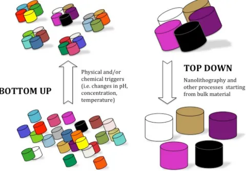
Basically, there are two approaches to fabricate micro and nanostructured materials:
top-‐down and bottom-‐up (Figure 1.1). These terms were first applied to the field of
nanotechnology by the Foresight Institute in 1989 in order to distinguish between molecular manufacturing (to mass-‐produce objects with conveyed order at the atomic scale) and conventional manufacturing (which can mass-‐produce large objects that are not atomically precise).
A top-‐down approach (also known as stepwise design and in some cases used as a synonym of decomposition) is essentially the breaking down of a system to gain insight into its compositional sub-‐systems, while bottom-‐up approaches seek to have smaller (usually molecular) components built up into more complex assemblies.
The top-‐down approach often uses the traditional workshop or microfabrication methods where externally controlled tools are used to cut, mill, and shape materials into the desired shape and order. Micropatterning techniques, such as photolithography and inkjet/laser assisted printing belong to this category.
Bottom-‐up approaches, in contrast, use the chemical properties of individual molecules
to push them to (a) self-‐organize or self-‐assemble into some functional conformation, or (b) rely on positional assembly. These approaches utilize the concepts of molecular self-‐ assembly and/or molecular recognition. Such bottom-‐up approaches should, broadly speaking, be able to produce devices in parallel and much cheaper than top-‐down methods, but could potentially be overwhelmed as the size and complexity of the desired assembly increases. Examples of top-‐down techniques exploiting molecular self-‐ organization are: Dip-‐pen Lithography (DPL), Local Oxidation Nanolithography (LON), Nanoimprint Lithography (NIL) and Soft-‐lithography.
1.3 Regenerative medicine for neural cells
Regenerative medicine is an emerging branch of translational research in tissue engineering and molecular biology, which deals with the "process of replacing, engineering or regenerating human cells, tissues or organs to restore or establish normal function". In addition to the therapeutic applications, such as a tissue grown in a patient or outside the patient and then transplanted, this field holds the promise of engineering damaged tissues and organs via stimulating the body's own repair mechanisms to functionally heal previously irreparable tissues or organs [2][3].
Regenerative medicine also refers to a group of biomedical approaches to clinical therapies that may involve the use of stem cells [4].
The bases of regenerative medicine and tissue engineering for either therapeutic or diagnostic applications are the ability to exploit living cells to fabricate tissue. Many results at a preclinical level have been shown, but we are still far from its clinical application. Actually most of the in vitro engineered tissues are dysfunctional: this is chiefly due to our limited understanding of the very fundamental principles underlying the complexity of cell life, with a restricted capacity of encoding bioactive signals in order to guide cells through the correct pathways of differentiation and biosynthesis. Cell functioning is, to a large extent, dependent on their microenvironment, which contains the surrounding extracellular matrix (ECM), other cells and soluble factors. Cells can sense ECM cues, such as composition, stiffness and topography signals through, for instance, integrin mediated adhesion, and can also communicate with neighboring cells[5][6]. The regulators of cell behaviors can easily classify into cell cues, ECM cues and soluble factors (Figure 1.2).
The current micro-‐ and nano-‐technologies interfacing synthetic materials and cell biology requires a better understanding of cell-‐surface interactions on the micro and nanometer scale. The development of these tools provides new means to understand the fundamental relationships between cells and their surrounding microenvironment, which underlie the physiology of human tissue.
One of core studies of biomaterials in the large field of regenerative medicine relies on understanding cell-‐material interactions, using the development of advanced materials and the surface patterning.
A significant topic in the field of regenerative medicine is the one related to the study of the central nervous system (CNS) diseases. Unfortunately the amount of CNS diseases is large and may be due to many causes, including mechanical trauma, infections as encephalitis and poliomyelitis, neurodegenerative disorders such as Alzheimer's disease and amyotrophic lateral sclerosis, autoimmune and inflammatory diseases such as multiple sclerosis or acute disseminated encephalomyelitis, and genetic disorders such as Krabbe's disease or Huntington's disease. Finally, tumors sited in CNS can cause severe illness and, when malignant, can be fatal.
Given this wide range of pathologies, it is fundamental to create novel route for investigating neural cell response to the environment signals starting from a completely new approach.
In this thesis two different secondary human neural cell lines, viz. NE4C neuroectodermal stem cells and SH-‐SY5Y neuroblastoma were used as cell line models. Both the cell lines have been extensively studied for many years as model of neural cell lines, more properly NE4C as neurons-‐astrocytes lineage [7][8] and SH-‐SY5Y as neuronal one [9][10]; furthermore their culture conditions allow one to obtain reproducible data about cell adhesion and proliferation. We already know the critical role of neurons in the CNS, but in the past, the neuronal network was considered the only important part in the CNS, and astrocytes were looked upon as “gap fillers”. More recently, the function of astrocytes has been reconsidered, and they are now thought to play a number of active roles in the brain, including the secretion and internalization of neuro-‐transmitters, biochemical support of the endothelial cells that form the blood– brain barrier, providing of nutrients to the nervous tissue, preserving the extracellular ion balance, repairing and scarring process of the brain and spinal cord following traumatic injuries.
A third further cell line: standard fibroblasts NIH-‐3T3 (from mouse) obtained and characterized in 1963 by G. Todaro and H. Green and used in a wide range of research studies and biomedical application has been employed in the adhesion and proliferation tests [11].
1.4 Implantable Organic Nano-‐Electronics: i-‐ONE project
A large part of my PhD work has been performed in the framework of the European project iONE-‐FP7 funded by the European Union Seventh Framework Program (FP7/2007-‐2013) under grant agreement n° 280772.
As literally reported in the technical annex “The vision of iONE project is to develop and test for the first time flexible organic electronics for the development and testing of Active Multifunctional Implantable Devices (AMIDs) leading to treatment of Spinal Cord Injury (SCI)”. The AMID has to be stable and safe, with high biocompatibility for reducing risk of a host versus graft immune response. The use of these flexible organic electronics devices (ultra-‐thin film organic field effect transistor (FET), organic electro-‐ chemical transistor, nanoparticle organic memory FET) will (i) advance the state-‐of-‐the-‐ art of implantable devices for SCI from passive to active layouts that will promote nerve regeneration by a combination of local stimuli delivered on demand, (ii) sense inflammation, and (iii) control the immune-‐inflammatory response.
My work has been devoted primarily to the mimicking of the local microenvironment for stem/precursor cell recruitment and differentiation (and delivering locally growth factors, neurotransmitters, and drugs.), by applying surfaces functionalization and micro and nanopatterning technologies.
The biomedical impact of the project has been demonstrated in vitro and in vivo. In vitro, the neural therapeutic plasticity induced by the iONE device has been evaluated on stem cells, which differentiated to neural progenitor cells, and then to neural cells. In vivo, the study of neural plasticity has been transferred to endogenous stem cells by implanting the iONE device into a contusion SCI animal model.
In conclusion, iONE, acquiring the knowledge and the technology required to regenerate the nerve in the niche of the injury, is the perfect example of nanotechnology application in regenerative medicine.
Bibliography
[1] Rajiv Saini, Santosh Saini, and Sugandha Sharma, “Nanotechnology: The Future Medicine,” J. Cutan. Aesthet. Surg., vol. 3, no. 1, pp. 32–33, 2010.
[2] J. Z. Gasiorowski, C. J. Murphy, and P. F. Nealey, “Biophysical cues and cell
behavior: the big impact of little things,” Annu. Rev. Biomed. Eng., vol. 15, pp. 155– 176, 2013.
[3] J. P. Fisher, A. G. Mikos, J. D. Bronzino, and D. R. Peterson, Tissue Engineering:
Principles and Practices. CRC Press, 2012.
[4] A. M. Riazi, S. Y. Kwon, and W. L. Stanford, “Stem cell sources for regenerative medicine,” Methods Mol. Biol., vol. 482, pp. 55–90, 2009.
[5] F. Gattazzo, A. Urciuolo, and P. Bonaldo, “Extracellular matrix: A dynamic
microenvironment for stem cell niche,” Biochim. Biophys. Acta, vol. 1840, no. 8, pp. 2506–2519, 2014.
[6] J. Barthes, H. Özçelik, M. Hindié, A. Ndreu-‐Halili, A. Hasan, and N. E. Vrana, “Cell Microenvironment Engineering and Monitoring for Tissue Engineering and Regenerative Medicine: The Recent Advances,” Biomed Res. Int., vol. 2014, 2014. [7] K. Schlett, B. Herberth, and E. Madarász, “In vitro pattern formation during
neurogenesis in neuroectodermal progenitor cells immortalized by p53-‐ deficiency.,” Int. J. Dev. Neurosci., vol. 15, no. 6, pp. 795–804, 1997.
[8] Z. Környei, V. Szlávik, B. Szabó, E. Gócza, A. Czirók, and E. Madarász, “Humoral and contact interactions in astroglia/stem cell co-‐cultures in the course of glia-‐induced neurogenesis.,” Glia, vol. 49, no. 3, pp. 430–444, 2005.
[9] R. A. Ross, B. A. Spengler, and J. L. Biedler, “Coordinate morphological and
biochemical interconversion of human neuroblastoma cells,” J. Natl. Cancer Inst., vol. 71, no. 4, pp. 741–747, 1983.
[10] J. Biedler, S. Roffler-‐Tarlov, M. Schachner, and L. Freedman, “Multiple
neurotransmitter synthesis by human neuroblastoma cell lines and clones.,”
Cancer Res., vol. 38, no. 11 Pt 1, pp. 3751–3757, 1978.
[11] G. J. Todaro and H. Green, “Quantitative studies of the growht of mouse embryo cells in culture and their development into established lines.,” J. Cell Biol., vol. 17, pp. 299–313, 1963.
Chapter 2 – Experimental and Fabrication
techniques
Here an overview of the main techniques used for fabrication, patterning and characterization is provided.
2.1 Fabrication and patterning techniques
2.1.1 Laser Assisted Bioprinting (LAB)
Parallel to the “scaffold based” strategy, in which cells are seeded onto porous structures, the bioprinting approach aims at constructing three dimensional biological structures or functional organs, layer-‐by-‐layer, from the bottom up[1]. Jet-‐based methods to print living cells have been widely reviewed [2][3]. Historically, laser-‐based printing techniques, such as laser-‐direct-‐writing, matrix-‐assisted pulsed laser evaporation (MAPLE), laser-‐induced forward transfer (LIFT) etc., have been used to spatially pattern solutions in 2D. Among them, the LIFT technique allows printing inorganic as well as organic material with micrometer resolution. Initially developed to transfer metals [4], the LIFT has been successfully improved to print biological material such as peptides, DNA, and cells [5][6].
Manipulation of picoliter to nanoliter droplets has been a challenge for several applications including biochemical surface patterning, tissue engineering, and direct placement of cells and biomaterials for wound dressing applications [7][8][[9]. In this regard, ejecting droplets via an actuator has emerged as a valuable technological advance addressing the issue of precise manipulation and deposition. A LIFT based bioprinter designed to print biological material was created and named BioLP (Biological Laser Printer) by Barron et al. [10]. LIFT based bioprinters or Laser Assisted Bioprinters (LAB) are comprised of three components: (i) a pulsed laser source, (ii) a target, called ‘ribbon’, from which a biological material is printed, and (iii) a receiving substrate that collects the printed material. The ribbon is made of a thin absorbing layer of metal (such as gold, titanium or stainless steel) coated onto a laser transparent support (usually glass). Biomolecules or cells are prepared in a liquid solution (i.e. physiological solution, water or culture media) that is called bioink, and deposited at the surface of the metal film, using various methods, like spin coating or doctor blade. The laser pulse induces vaporization of the metal film, resulting in the production of a jet of liquid solution, which is deposited onto the facing substrate (Figure 2.1).
Figure 2.1: Mechanism for laser-‐induced droplet ejection. A vapour bubble is generated by vaporization of the absorbing layer and/or the first molecular layers of the liquid film. At a given viscosity, depending on bubble dynamics, jetting (b) is observed for intermediary values of fluences. For lower fluences (a), the bubble collapses far from the free surface without generating a jet. For high fluences (c), the bubble bursts to the surface, generating sub-‐micrometer droplets. Increasing viscosity leads to increased threshold values between the subthreshold, jetting and plume regimes
To control the surface tension effects during printing, glycerol 1:1 is added to the final volume of the solution. Glycerol is a simple polyol (sugar alcohol) compound, colorless, odorless, very viscous and widely used in pharmaceutical formulations. Glycerol has three hydroxyl groups that are responsible for its solubility in water and its hygroscopic nature. Glycerol improves the process not only because of his high viscosity that helps in the creation of the bioink jet, but also because glycerol is not toxic and does not alter the bioink molecules features (i.e. protein structure or cell fate).
Non-‐contact printing is obtained through a jet formation which occurs, at a microsecond time scale, above a laser energy density threshold whose value depends on the rheological properties of liquid films and the thickness of the metallic absorbing layer [11]. By analogy with other studies in physics, it has been proposed that jet formation could be related to bubble dynamics [12], [13]. Bubble growth depends mainly on viscosity and surface tension of the liquid, while bubble collapsing is related to the distance between the bubble front and the free surface.
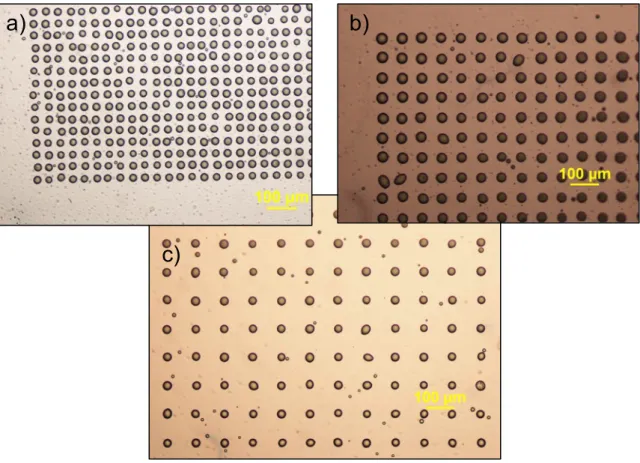
Considering the LAB, the resolution of printing, i.e. the size and proximity of the printed droplets, depends on parameters like the thickness of the layer of the bioink coated onto the ribbon, the surface tension and the viscosity of the bioink, the wettability of the substrate, the laser fluence, the air gap between the ribbon and the substrate [11]. The compromise between these parameters in order to obtain the desired resolution of printing may thus vary depending on the type of material being printed. The influence of these parameters on jet formation is still under investigation [14]. Therefore, controlled bioprinting (i.e. absence of splashing, controlled size of the liquid droplet) by LAB remains challenging and the highest resolution of cell printing has not yet been attained (Fig. 2.1).
LAB Applications
Laser Printing was first investigated for the fabrication of microelectronic circuits. Thereby, lines of conductive material were printed to connect micro devices or as antennas [15]. For biological applications, different groups printed cells, proteins and DNA [16][17]. Serra et al. printed a biosensor, consisting of micrometric patterns of deposited droplets containing DNA [18]. After deposition, the microarray was hybridized with the complementary strands of the transferred DNAs, each kind tagged with a different dye. The fluorescence assay was positive, demonstrating that hybridization occurred only in the droplets where specific DNA was deposited. This study demonstrates LIFT techniques as a suitable strategy for biosensors preparation without significant biomolecular damage during the laser printing procedure. Furthermore, pieces of tissue from a histological section or living adherent cells located on a polymer foil have been printed by Vogel et al [19].
In this thesis, Laser Assisted Bioprinting has been performed using ScribaR Laser Marker (Figure 2.2).
Figure 2.2: (a) ScribaR Multifunctional Laser Marker. (b) The ScribaR chamber with the sample holder, the lightning and microscope-‐camera system. The laser beam remains focused on the same point, while the sample holder is moving (in x, y, z) due to a very accurate micrometric motor stage.
2.1.2 Soft Lithography
Soft lithography refers to a family of techniques for fabricating or replicating structures
using "elastomeric stamps, molds, and conformable photomasks". It is called "soft" because it uses elastomeric materials, most notably PDMS (polydimethylsiloxane). Soft lithography is generally used to construct features measured on the micrometer to nanometer scale.
Photolithography, since 1959, has always been the most successful technology in microfabrication. The photolithographic techniques currently used for manufacturing microelectronic structures are based on a projection-‐printing system in which the image of a reticle is reduced and projected onto a thin film of photoresist that is spin-‐coated on a wafer through a high numerical aperture lens system.
Microelectronics is based on photolithography and associated techniques that are used for fabricate integrated circuits. Microelectromechanical systems are made-‐up by silicon micromachining; these techniques were the first to be improved to the manufacture of microstructures for biological research. The first example was the use of photolithography in the fabrication of DNA arrays [20], [21]. Anyway, photolithography is limited in its application to biotechnology and biology for several reasons: is intrinsically expensive (for most applications, cost is a dominant parameter), it gives limited control over surface properties, is often not directly suitable for proteins and cells, the time procedure to reach a prototype from a design can be long, and the techniques are unfamiliar and inaccessible to most biologists.
For fabricating microstructures for biological applications, soft lithography overcomes many of the limitations of photolithography because it allows working with water solutions thus allowing controlling the molecular structure of surfaces by patterning complex molecules such as proteins or nucleic acids [22]. A number of non-‐ photolithographic techniques have been demonstrated for fabricating (and in some cases for manufacturing) high-‐quality microstructures and nanostructures: microcontact printing (μCP), replica molding (REM), microtransfer molding (μTM), micromolding in capillaries (MIMIC) and solvent-‐assisted micromolding (SAMIM) and Lithographically Controlled Wetting (LCW). PDMS, the most used elastomeric material, is supplied, in its most widely commercialized version (Sylgard 184, Dow Chemicals), as two components, a base and a curing agent. PDMS displays many relevant properties. It has a Young’s modulus that makes it a moderately stiff elastomer (1 MPa). It is nontoxic and readily available commercially. It is intrinsically very hydrophobic (advancing contact angle of water of 110°), but its surface can be converted to a hydrophilic form (±10°) by common plasma treatments.
Lithographically controlled wetting (LCW)
LCW is a simple, fast and sustainable wet-‐patterning process that exploits the self-‐ organization of soluble materials, that allows a fine spatial control provided by the
features of the employed stamp [23]. In principle, LCW can be used with any soluble compound or material. It can be performed without special instrumentation and does not require a clean room. Compared with other lithographic methods, LCW does not rely on specific interactions between the molecules and the surface; therefore, it has a wide range of potential applications, as demonstrated by the large variety of soluble materials reported in the literature to which it could be applied. Although LCW was developed originally for patterning organic semiconductors, its application was extended to many functional materials such as inorganic salts, coordination compounds, coordination polymers, molecular magnets, nanoclusters, electroluminescent compounds, sensing materials for pH and others.
Recently, LCW was also applied to biomolecules, where it can have an important role in the fabrication of biomaterial interfaces in biologically inspired applications and in medical devices. LCW has been already applied in some experiments for fabricating patterns aimed to guide the adhesion, migration and proliferation of cells [24].
A schematic overview of the LCW process is shown in Figure 2.3.
Figure 2.3: LCW (a–c) Scheme of printing using prefabricated spacers (a) in the standard (b) and diluted (c) regime. (d–f) Scheme of printing using a floating stamp (d) in the
When a stamp is placed in contact with a liquid thin film spread on a substrate, instability of the fluid layer develops and capillary forces pin the solution to the stamp protrusions, giving rise to an array of menisci. As the solvent evaporates, the solution forms a subfemtoliter fluid cell under each stamp protrusion (assuming a stamp feature ranging between 100 and 500 nm and a stamp-‐ substrate distance between 50 and 200 nm, sizes commonly used in LCW). When the solution reaches supersaturation, the solute precipitates onto the substrate within the menisci, giving rise to a deposit replicating the protrusion of the stamp.
Microcontact Printing (μCP)
Microcontact printing is the most famous soft-‐lithographic method: the strategy is using a relief patterns onto an elastomeric stamp of PDMS to create patterns of self-‐assembled monolayers (SAMs) of a printable compound (the ink) on the surface of a substrate through conformal contact. Its potential applications range from microelectronics and surface chemistry to cell biology. It requires printable materials chemically grafted to the substrate or able to form SAMs. The procedure is remarkably simple and is showed in Figure 3.4. An elastomeric PDMS stamp is used to transfer molecules of the ink to the surface of the substrate by contact. After printing, a different SAM can be formed on the underivatized regions by washing the patterned substrate with a dilute solution containing the second molecule (Figure 2.4).
Figure 2.4: μCP technique scheme.
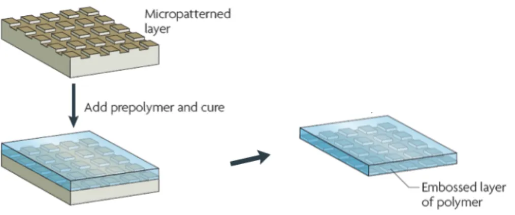
Replica Molding (REM)
Replica molding duplicates the information, such as the shape, the morphology, and the structure, present in a master (Figure 2.5). It is a procedure that accommodates a wide range of materials. It also allows duplication of 3D topologies in a single step, whereas photolithography is not able to replicate such structures. It has been used for the mass production of surface relief structures such as diffraction gratings, holograms, compact disks (CDs), and micro tools. Replica molding with an appropriate material (usually in the form of a precursor) enables highly complex structures in the master to be faithfully
duplicated into multiple copies with nanometer resolution in a reliable, simple, and inexpensive way. The fidelity of replica molding is determined by van der Waals interactions, wetting and kinetic factors such as filling of the mold. These physical interactions should allow more accurate replica of features that are smaller than 100 nm than does photolithography, which is limited by optical diffraction.
Figure 2.5: Replica Molding technique scheme.
2.1.3 Electrochemical desorption of Self-‐Assembled Monolayers
Self-‐assembled monolayers (SAM) of organic molecules are molecular assemblies formed spontaneously on surfaces by adsorption and are organized into more or less large ordered domains. In nature, self-‐assembly results in supermolecular hierarchical organizations of interlocking components that provides very complex systems [25]. SAMs offer unique opportunities to increase fundamental understanding of self-‐ organization, structure-‐property relationships, and interfacial phenomena. The ability to tailor both head and tail groups of the constituent molecules, makes SAMs excellent systems for a more fundamental understanding of phenomena affected by competing intermolecular, molecular-‐substrates and molecule-‐solvent interactions like ordering and growth, wetting, adhesion, lubrication, and corrosion. SAMs being well defined and accessible are good model systems for studies of physical chemistry and statistical physics in two dimensions and the crossover to three dimensions.
SAMs provide the needed design flexibility, both at the individual molecule and at the material levels and offer a vehicle for investigating both specific interactions at interfaces and the effect of increasing molecular complexity on the structure and stability of two-‐dimensional assemblies.
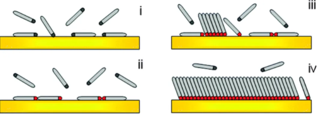
SAMs are ordered molecular assemblies formed by the adsorption of an active surfactant on a solid surface [26] (Figure 2.6).
Figure 2.6: Scheme of the different steps taking place during the self-‐assembly of alkanethiol on Au: (i) physisorption, (ii) lying down phase formation, (iii) nucleation of the standing up phase, (iv) completion of the standing up phase.
This simple process makes SAMs inherently manufacturable and thus technologically attractive for building superlattices and for surface engineering. The order in these two-‐ dimensional systems is produced by a spontaneous chemical arrangement at the interface as the system approaches equilibrium.
In our experiments, oligo ethylene-‐glycol-‐terminated alkylthiols (HS-‐(CH2)11-‐ (OCH2CH2)6-‐OH: TOEG6) were used for generating a SAM on a thin gold layer deposited on a glass slice.
Electrochemical desorption (ECD) of self-‐assembled monolayers is an important process that can dynamically modify surface properties: an electrical stimulus is used to desorb molecules that form SAM by breaking the chemical bond between Au and S:
Au − SR + e! → Au! + RS!
Electrical stimulus can also be used to modify electronic state or molecular conformation of SAMs, and to help deposit molecules of SAMs. Although the assembly of alkanethiols onto Au is a spontaneous process, its stability varies at different range of electrochemical potentials. To conduct an ECD we need at least two electrodes. The
working electrode, which makes contact with the SAM, must apply the desired potential
in a controlled way and facilitate the transfer of charge to and from the sample. A second electrode acts as the other half of the cell and must have a known potential with we measure the potential of the working electrode, furthermore it must balance the charge added or removed by the working electrode. While this is a viable setup, it has a number of limitations: it is extremely hard for an electrode to maintain a constant potential while passing current to counter redox events at the working electrode. To solve this problem, two separate electrodes have the individual roles of supplying electrons and providing a reference potential. The reference electrode is a half cell with a known reduction potential and it acts as reference in measuring and controlling the working
electrode's potential and at no point does it pass any current. Then we have a counter electrode that passes all the current needed to balance the current observed at the
working electrode. These three electrodes, the working, reference, and counter, make up
the “three electrode system”.
For studies of ECD, SAMs are usually immersed in an aqueous or ethanol solution with an electrolyte, for example KOH, at a neutral or basic pH. Both the thiolates and the bare Au surface become solvated. The potential is applied between the working electrode and the reference electrode while the current is measured between the working electrode and the counter electrode. The thiols diffuse from the surface or sometimes tend to remain on the electrode surface and form a molecular assembly, preventing the residual SAM from desorbing and even redeposited repetitively onto the Au surface. Desorption process is reversible: the thiols can re-‐adsorb onto the Au surface when the applied negative potential is removed [27]. The potential at which the desorption of the SAMs occurs depends on several factors, such as the length of the alkyl chain, the degree of ordering and the number of intermolecular interactions within the organic film, and the crystallinity of the substrate (Au) [28].
A typical desorption potential for n-‐alkanethiolates is -‐1.0 V with respect to an Ag/AgCl (satd. KCl) reference electrode. Thiols with short chain tend to undergo reductive desorption at potentials less negative than -‐1.0 V. Various methods can be used to characterize ECD, such as cyclic voltammogram (CV), chronoamperometry, electrochemical quartz crystal microbalance, surface plasmon resonance (SPR), fluorescence microscopy, scanning tunneling microscopy (STM) and so forth.
2.1.4 Nanografting
This technique combines Atomic Force Microscopy (AFM, see below, section 2.2.2) with SAM functionalized surfaces. Using an AFM tip it is possible to “scan” the SAM and
scratch it along a defined pattern. As a higher force is applied during the scanning, the
matrix thiol molecules are removed by the tip and transported into the solvent. Thiol molecules contained in the solution immediately adsorb onto the freshly exposed gold area following the scanning track of the atomic force microscope tip to form designed nanostructures. The produced nanopatterns can then be characterized in situ by the same atomic force microscope tip at a reduced force.
The whole procedure occurs in liquid environment: more specifically, the solution that contains a different self-‐assembly molecule that one wants to replace the first one (Figure 2.7).
Figure 2.7: Nanografting scheme. An AFM tip reaches the SAM and, landing on it, begins to scratch the monolayer. The empty space is filled by another molecule.
Tip force, scanning speed and lines density per units of area, are adjustable for locally modify SAM structure and molecules packing. AFM tip induces mechanical stress that allows local exchanges of surface material with molecules in the liquid suspension. Otherwise, friction forces between tip and surface can provide extra thermal energy for overtaking desorption energetic barrier, as observed by J. Liang in DNA nanografting [29].
Nanografting technique shows very critical opportunities in the field of nanomaterials and in the nanotechnology sector, allowing fabrication of nanostructures with functional groups as –OH, -‐COOH, -‐CHO, -‐NH2, NHS, biotin, -‐CF3, carbohydrates and nucleotides. This versatility has been demonstrated by the fabrication of patches of objects displaying of large sizes such as metal nanoparticles (NPs), DNA and proteins [30].
2.2 Characterization techniques
2.2.1 Scanning Electron Microscopy (SEM)
The scanning electron microscope (SEM) uses a focused beam of high-‐energy electrons to generate a variety of signals at the surface of solid specimens. The signals that derive from electron-‐sample interactions reveal information about the sample including external morphology (texture), chemical composition, crystalline structure and orientation of materials making up the sample. In most applications, data are collected
over a selected area of the surface of the sample and a 2-‐dimensional image is generated that displays spatial variations of these properties. Areas ranging from approximately 1 cm to 5 microns in width can be imaged in a scanning mode using conventional SEM techniques (magnification ranging from 20X to approximately 30,000X, spatial resolution of 50 to 100 nm). The SEM is also capable of performing analyses of selected point locations on the sample; this is especially useful in qualitatively or semi-‐ quantitatively determination of the chemical compositions (using Energy Dispersive X-‐ ray Spectrometry, EDS), crystalline structure, and crystal orientations (using Electron Back Scattered Diffraction, EBSD).
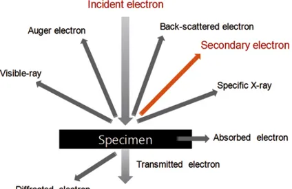
Accelerated electrons carry significant amounts of kinetic energy and this energy is dissipated by electron-‐sample interactions when the incident electrons are decelerated in the solid sample. These signals produced by this interaction include secondary electrons (that produce SEM images), backscattered electrons (BSE), diffracted backscattered electrons (EBSD that are used to determine crystal structures and orientations of minerals), photons (characteristic X-‐rays that are used for elemental analysis and continuum X-‐rays), visible light (cathodoluminescence–CL) and heat. Secondary electrons and backscattered electrons are commonly used for imaging samples: secondary electrons are most valuable for showing morphology and topography on samples and backscattered electrons are most valuable for illustrating contrasts in composition in multiphase samples (i.e. for rapid phase discrimination). X-‐ ray generation is produced by inelastic collisions of the incident electrons with electrons in discrete orbitals (shells) of atoms in the sample. As the excited electrons return to lower energy states, they yield X-‐rays of a fixed wavelength (that is related to the difference in energy levels of electrons in different shells for a given element). Thus, characteristic X-‐rays are produced for each element in a mineral that is "excited" by the electron beam (Figure 3.8).
Figure 2.8: Scheme of the interaction between an electron beam and the sample.