1
Alma Mater Studiorum – Università di Bologna
DOTTORATO DI RICERCA IN
Ingegneria Civile, Chimica, Ambientale e dei Materiali
Ciclo XXIX
Settore Concorsuale di afferenza: 09/D3 – Impianti e processi industriali chimici Settore Scientifico disciplinare: ING-IND/25 – Impianti Chimici
ANALYSIS OF SUSTAINABLE
TECHNOLOGIES
FOR ACID GAS REMOVAL
Presentata da: Alessandro DAL POZZO
Coordinatore Dottorato
Relatore
Prof. Ing. Luca VITTUARI
Prof. Ing. Valerio COZZANI
Correlatori
Prof. Ing. Alessandro TUGNOLI
Ing. Giacomo ANTONIONI
2
Index
Abstract ... 5
General Introduction ... 6
PART I - Acid gas removal by dry processes 1 Acid gases ... 10
1.1 Typical acid pollutants in flue gases from combustion processes ... 10
1.2 Sulfur dioxide and acid rains ... 10
1.3 Hydrogen halides and airborne toxicity ... 11
1.4 Carbon dioxide and the climate change challenge ... 13
1.5 Acid neutralisation ... 14
2 Acid gas abatement in Waste-to-Energy plants: state of the art ... 16
2.1 Overview of air pollution control in the waste incineration sector ... 16
2.2 Solid sorbents for acid gas removal: Ca-based sorbents ... 17
2.3 Solid sorbents for acid gas removal: Na-based sorbents ... 19
2.4 Review of the latest developments in dry sorbent injection technologies... 21
3 Carbon capture with solid sorbents: state of the art ... 26
3.1 The concept of carbon capture and storage ... 26
3.2 Approaches to CO2 capture ... 26
3.3 Perspective of carbonate looping in pre- and post-combustion CO2 capture ... 29
4 Research needs and motivation of the study... 31
4.1 Challenges in the use of sorbents for acid gas removal ... 31
4.2 Overcoming the limitations of gas-solid reactions by process optimisation ... 32
4.3 Overcoming the limitations of gas-solid reactions by synthesis approaches ... 32
References (Part I) ... 34
PART II - Application to HCl and SO2 removal in Waste-to-Energy plants 5 Experimental study of acid gas removal processes: the reaction between Ca(OH)2 and HCl . 41 5.1 The reaction ... 41
5.2 Set-up of a dedicated laboratory apparatus ... 42
5.3 Materials and experimental procedure ... 44
5.4 HCl removal monitored by infrared spectroscopy ... 46
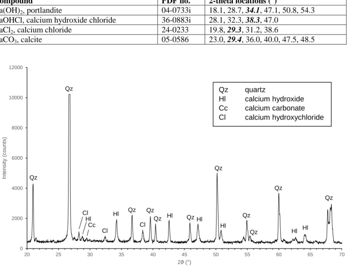
5.5 Identification of the solid reaction product ... 50
6 Phenomenological model for acid gas removal processes ... 53
3
6.2 The issue of incomplete conversion ... 54
6.3 Phenomenological model: the grain model framework ... 56
6.4 Phenomenological model: the crystallisation and fracture submodel ... 63
6.5 Model input and output parameters ... 66
6.6 Model validation against literature data ... 69
6.7 Model validation against experimental data ... 76
7 Operational model for process optimisation of acid gas removal systems ... 80
7.1 Formulation of the operational model ... 80
7.2 Calibration of the model with operational data from Waste-to-Energy plants ... 82
7.3 Case study: optimisation and benchmarking of a two-stage treatment system ... 84
7.4 Methodology ... 86
7.5 Benchmarking data ... 87
7.6 Cost estimate ... 90
7.7 Optimal configuration of the two-stage system and benchmarking results ... 95
7.8 Influence of uncertain parameters and Monte Carlo sensitivity analysis ... 97
8 Sustainability analysis of acid gas removal systems ... 103
8.1 A holistic approach to environmental protection ... 103
8.2 Definition of the case study ... 104
8.3 Data inventories and associated uncertainties ... 108
8.4 Characterisation approach and adopted indicators ... 111
8.5 Two-stage system: environmental and economic optima ... 113
8.6 Comparison of the alternative acid gas removal systems ... 116
8.7 Closing remarks on single stage vs. multistage dry treatment systems ... 123
References (Part II) ... 124
Part III - Application to CO2 capture by MgO-based sorbents 9 Development of MgO-based sorbents ... 135
9.1 Alternatives to limestone in carbonate looping technologies ... 135
9.2 Use of residues from dry acid gas removal as CO2 sorbents ... 136
9.3 Potentiality of MgO as a CO2 sorbent ... 140
9.4 Enhancement of MgO reactivity with molten salt promotion ... 141
9.5 Synthesis protocol for alkali metal nitrate-coated MgO-based CO2 sorbents ... 142
10 Analysis of the carbonation of MgO-based sorbents ... 146
10.1 CO2 uptake ... 146
10.2 In situ analysis of carbonation: DRIFTS spectroscopy ... 153
10.3 In situ analysis of carbonation: synchrotron-based XRD/PDF analysis ... 155
10.4 Performance of MgO-based sorbents over repeated carbonation/calcination cycles ... 158
4
References (Part III) ... 161
Conclusions ... 167
List of publications ... 169
5
Abstract
Acid gases, such as sulphur dioxide and hydrogen halides and – in a broad sense – carbon dioxide, are typical pollutants generated by combustion processes. Their removal by means of solid sorbents represent an efficient and cost-effective approach in dry acid gas treatment systems for waste incineration flue gas, while for CO2 capture the process is exploratively studied as a promising
alternative to amine scrubbing. The present study addressed both aspects.
In waste incineration flue gas cleaning, acid gas removal by sorbent injection is a well-established process. Nonetheless, a thorough understanding of the gas-solid reactions involved in the process has not been reached yet and, thus, the operation of dry treatment systems is still highly empirical. In the present study, the process was analysed using different levels of detail: from the microscopic level of a lab-scale experimental campaign and phenomenological description of the kinetic and mass transfer phenomena governing the gas-solid reaction to the macroscopic level of techno-economic and environmental assessment of alternative full-scale dry treatment systems.
With respect to CO2 capture technologies, the process is still in the development stage and research
is focused on the identification of highly-efficient sorbents. The present study analysed the enhancement of CO2 uptake potential of magnesium oxide, a promising sorbent for
intermediate-temperature carbon capture, by means of coating with alkali metal molten salts.
The joint analysis of gas-solid reaction for flue gas cleaning in two diverse contexts allowed the identification of common issues and of possible shared solutions.
6
General Introduction
“A clever person solves a problem. A wise person avoids it.” This quote attributed to physicist Albert Einstein is frequently used when referring to environmental issues to state an important concept: prevention is better than cure.
Historically, environmental problems have been faced by introducing “cures”, i.e. pollution mitigation measures. Air pollution has been fought by implementing so-called end-of-pipe technologies, like dedusting equipment in energy plants or catalytic converters in cars, to treat emissions and reduce the load of pollutants. Likewise, waste accumulation has been faced by operating treatment and incineration plants aimed at reducing and sanitising the refuses generated by society.
In the last decades, a novel approach to environmental protection has been increasingly put into practice: pollution prevention. Instead of managing a pollutant only after its emission, thus focusing on the reduction of its impact on the environment, pollution prevention aims to eliminate pollution at its source. Typical examples of prevention measures are the modification of a production process in order to generate less waste, the substitution of toxic chemicals with non-toxic alternatives, the implementation of water and energy conservation strategies, the recycling and reusing of materials. Intertwining concepts proper of engineering and management, of design and sociology, pollution prevention has been truly a Copernican revolution in the field of environmental protection.
Yet, pollution prevention cannot be an all-healing panacea. Although prevention strategies can significantly curb our environmental impact, human activity still needs inherently polluting activities. Industries such as ceramics, glass manufacturing or steelmaking, which basically relies on thermal processes, unavoidably emit airborne pollutants. The sorted fractions of municipal and industrial waste can be recycled and reused to greater extent, but the management of residual unrecyclable waste fractions still requires incineration, in order to avoid landfilling. Even in the power sector, despite the remarkable progresses of renewable sources, the consumption of fossil fuels is expected to steadily increase in the upcoming years, as the thirst for cheap energy of emerging economies keeps growing and the political support for CO2 emission targets worldwide
remains lukewarm.
In this framework, the “clever person” of Einstein’s quote is still needed. Since we are not going to get rid of certain polluting activities any time soon, the optimisation of current pollution mitigation technologies and the implementation of new ones will still be relevant points in the environmental protection agenda. Problems typical of the process and chemical engineering await solution in order to further improve current end-of-pipe approaches and to start up new technologies to tackle new target pollutants such as CO2.
***
The present PhD work aimed at offering a contribution towards a better understanding of theoretical and operational aspects in acid gas removal processes of either current industrial relevance (HCl and SO2 removal in waste incinerators) or perspective interest (pre- or post-combustion CO2
capture). The manuscript is organised as follows.
Part I of the thesis provides the general framework in which the present PhD project finds its motivation. Targets of the study are acid gases: HCl, SO2, HF and, in a broad sense, CO2. Their
7
processes are illustrated in chapter 1. Chapters 2 and 3 provide the state of the art of acid gas removal in Waste-to-Energy plant and CO2 capture technologies, respectively. Chapter 4 outlines
the pressing research needs which motivates the present study.
Part II is focused on the analysis of acid gas removal by solid sorbents in the Waste-to-Energy context. The process is explored at different levels. Chapter 5 shows an experimental investigation of the gas-solid reaction between Ca(OH)2 and HCl (the most relevant target acid pollutant for WtE
plants), testing the influence of different operating parameters and clarifying doubts regarding the actual solid product of chloridisation. Chapter 6 presents a phenomenological model for dry acid gas removal, based on the description of kinetics and mass transfer phenomena. The model is validated against both relevant literature data and experimental data illustrated in the previous chapter. Chapter 7 shifts the attention to a simplified approach to acid gas removal modelling: an empirical model, calibrated on operational plant data, is presented as a useful tool for process optimisation of full-scale dry treatment systems. This modelling approach is applied to an economic comparison between two-stage and benchmark single stage dry acid gas removal configurations. Chapter 8 expands the economic process optimisation shown in chapter 7 to a broader sustainability analysis, taking into account the indirect environmental impacts generated by the supply and disposal chains of solid reactants and residues. Final considerations about the overall optimisation of acid gas removal systems are drawn.
Part III reports the investigation of CO2 capture by MgO-based sorbents. Chapter 9 introduces the
research of new CO2 sorbents (also briefly discussing the possibility of re-use of aicd gas removal
solid residues for CO2 capture) and illustrates potentialities and limitations of MgO as CO2 sorbent,
identifies molten salt promotion as a viable route for the enhancement of reactivity and presents a facile and reproducible synthesis protocol for alkali metal nitrate-coated MgO sorbents. Chapter 10 reports the CO2 uptake performances of the synthesised materials and delves into a spectroscopic
investigation of the actual mechanisms governing MgO carbonation, eventually providing indications for further research in the area.
The general conclusions highlight the cross problems identified between the two gas-solid removal processes respectively shown in Part II and Part III and the common strategies carried out to overcome them.
9
Part I
10
1 Acid gases
1.1 Typical acid pollutants in flue gases from combustion processes
Acid gases are a class of atmospheric pollutants emitted by combustion processes, whose main components are sulphur dioxide and hydrogen halides. They are grouped on the basis of their acid behaviour, which determines their hazardous profile as corrosive substances, toxic compounds and precursors of environmental acidification, but also defines the chemical principle allowing their abatement in flue gas cleaning systems (see section 1.5).
Figure 1.1 summarises the expected concentration range of acid pollutants in raw exhaust gas for different industrial processes. The present thesis will make specific reference to the waste incineration sector, since waste-to-energy (WtE) facilities – especially in Europe – are the most challenging proving ground for acid gas removal processes, because of the combined effect of stricter emission limit values at stack and higher loads of pollutants in the untreated gas. Nonetheless, findings and indications obtained for WtE plants are exportable to other relevant industrial contexts where acid gas control is a concern and more demanding emission regulations have been recently issued (BREF GLS, 2012). Furthermore, the present thesis identifies an interesting parallelism between concepts and issues proper of dry acid gas treatment and the challenges faced by the carbonate looping technology in the novel field of CO2 pre- and
post-combustion capture (see chapter 3).
Figure 1.1. Typical concentration range of acid contaminants in the flue gas of some industrial processes.
1.2 Sulfur dioxide and acid rains
Sulphur dioxide (SO2) is a typical fuel-related contaminant of combustion off-gas. In waste
incineration, its presence in the flue gas is related to the combustion of organic substances, due to the elementary oxidation reactions of S and H2S (Niessen, 2002). It is a major air pollutant, carrying
significant impacts upon human health and integrity of habitats (EPA, 1999).
In particular, sulfur dioxide emissions have been a historical precursor to acid rain. The collective term covers a variety of phenomena connected to the atmospheric precipitation of acid substances (acid rainfall, snowfall and fog). In addition to moist deposition, acid gases can also precipitate due to dry deposition on particulate matter, fumes and aerosol. Acid precipitations, having a pH lower
0 500 1000 1500 2000 2500
COAL CER GLASS MSWI
Concentration in untreated flue gas (ppm)
HCl, HF
SO
2 MUNICIPALSOLID WASTEINCINERATORS GLASSMANUFACTURING CERAMICS INDUSTRY COAL-FIRED POWERPLANTS11
than 5 (Baird and Cann, 2008), cause soil acidification, suppress microbial fauna, wash nutrients out of terrains, dissolve and mobilise other toxic substances like aluminium. All these effects contribute to the weakening of vegetation. Thin soils, poor in organic matter, like the alpine soils, are particularly vulnerable (Krug and Frink, 1983). Likewise, effects on aquatic ecosystems are severe, since rivers and lakes – being the final receptors of meteoric waters – suffer the accumulation of the precipitated acid substances.
Sulfur dioxide, along with other precursors like nitric oxide (NO), is the primary pollutant responsible for acid rain. During the transport of the air masses containing SO2, the primary
pollutant is transformed in the actual strong acid provoking acid rain, i.e. sulphuric acid (H2SO4):
𝑆𝑂2+ 𝐻2𝑂 +
1
2𝑂2 → 𝐻2𝑆𝑂4 1.1
Then, acid rain containing H2SO4 can precipitate far downwind from the original source of SO2
emissions. For instance, acid rain was first scientifically characterised in Norway and Sweden in the 1960s (Revelle and Revelle, 1992) and the Swedish scientist Svante Odén found enough evidences linking the acidification of Swedish lakes to pollutants emitted abroad (Odén, 1968) to allow Sweden drawing international attention on the issue of transboundary pollution at the 1972 United Nations Conference on the human environment (Schreurs, 2007). Nowadays, a similar pattern of long-range transport of pollutants is observed in China, where the South-eastern regions suffer the main effects of acid precipitations although coal burning and SO2 emissions are mainly
concentrated in North-eastern regions (Tang and Wu, 2012). 1.3 Hydrogen halides and airborne toxicity
Hydrogen halides are diatomic inorganic compounds formed by a hydrogen atom and a halogen. Hydrogen chloride is the most abundant acid gas in flue gases generated in municipal solid waste incinerators. The main reaction responsible for the emission of HCl during waste combustion is the dechlorination of Cl-containing plastics (Matsukata et al., 1996):
𝑅 − 𝐶𝑙 + 𝑂2 → 𝐻𝐶𝑙 + 𝐶𝑂2+ 𝐻2𝑂 1.2
Cl-containing plastics include polyvinyl chloride (PVC, 59.0 wt. % of Cl), polyvinylidene chloride (PVDC, 73.2 wt. % of Cl) and polychloroprene (Neoprene, 39.5 wt. % of Cl). Conversely, inorganic chlorine (e.g., table salt) cannot release HCl at the typical temperatures attained in the combustion chamber (Wey et al., 2001).
Hydrogen fluoride is the second most relevant halide released by waste combustion, although its concentration in the exhaust gas is usually 2-3 order of magnitudes lower than that of HCl (Dal Pozzo et al., 2017). Specific industrial waste fractions can be particularly rich in fluorine, like automotive shredder residues, which show F mass fractions up to 0.5-0.75% in dry waste, generally coupled with a high Cl content (Viganò et al., 2010).
Similarly, halogens with higher atomic number are transformed during combustion in the respective halides. For example, the combustion of electronic boards containing brominated flame retardants gives rise to the emission of hydrogen bromide (Barontini et al., 2005). Likewise, exceptionally high loadings of pharmaceutical waste containing iodine can provoke a spike in hydrogen iodide concentration in flue gas (Zemba et al., 2013), generating a purple-tinted plume (Figure 1.2) and an understandable alarm in the nearby population.
12
Figure 1.2. Purple-coloured plume emanating from the exhaust stack of the WtE plant in Pisa (Italy) due to
hydrogen iodide emission (March 2007).
The emission of hydrogen halides can cause harm to both human health and ecosystem integrity. Concerning damages to human health, the halides are classified as toxic compounds. An evaluation of the dangerousness of acid gases is given by toxicological threshold values such as the ones presented in Table 1.1. The IDLH (Immediately Dangerous to Life or Health) is the minimum concentration of an airborne contaminant for which a 30 min exposure is “likely to cause death, or
immediate or delayed permanent adverse health effects, or prevent escape from such an environment”. The AEGL (Acute Exposure Guideline Levels) values are the respective
concentrations of an airborne pollutant which cause irritation and reversible effects (AEGL-1), permanent or long-term damages (AEGL-2), death risk (AEGL-3).
Hydrogen chloride is irritating for eyes and skin. It forms corrosive hydrochloric acid on contact with water found in body tissue. Acute exposure can cause eye burns, inflammation and ulcer in the respiratory tracts and, in severe cases, pulmonary edema (EPA, 1999). Concerning chronic effects, long-term exposure to HCl is linked to gastritis, chronic bronchitis, dermatitis and photosensitisation (Hazardous Substances Data Bank, 1993; CalEPA, 1999).
Hydrogen fluoride is extremely corrosive and toxic. The affinity of the F- anion towards the ubiquitous biologically important Ca2+ and Mg2+ cations can cause severe interference with blood, bone and tissue calcium levels (Hoffman et al., 2007). For instance, the CML-IA methodology for life cycle assessment attributes to HF a human toxicity potential three orders of magnitude higher than those of HCl and SO2 (Huijbregts et al., 2000),
Table 1.1. AEGL (60 min) and IDLH threshold limit values for the main acid gaseous species. Source:
CAMEO Database, U.S. EPA.
Composto AEGL-1 (ppm) AEGL-2 (ppm) AEGL-3 (ppm) IDLH (ppm) SO2 0.2 0.75 30 100 HCl 1.8 22 100 50 HF 1 24 44 30
13
1.4 Carbon dioxide and the climate change challenge
Although not usually included in the acid gas category, carbon dioxide (CO2), the product of
complete combustion of carbon, is slightly acidic in nature. Its concentration in a typical flue gas exiting from a combustion chamber ranges from 8 vol. % for waste-to-energy plants (BREF WI, 2006) to 15 vol. % for coal-burning power plants (Dieter et al., 2014).
Carbon dioxide is not a pollutant stricto sensu, being non-toxic and non-harmful, unlike the acid gases presented so far. However, worldwide concern has grown in the last decade on the causality between CO2 emissions and global warming. CO2 is a so-called greenhouse gas, i.e. it absorbs and
emits thermal radiation in the infrared range, thus producing an effect which is actually essential in keeping Earth surface at an average temperature compatible with life. Yet, the atmospheric concentration of CO2 has increased by more than 45% since 1750 (see Figure 1.3), as a
consequence of human industrial activity and fossil fuel utilization, and this unprecedented trend has strengthened the radiative forcing of the greenhouse effect, leading to a steady increase in average global surface temperature (Figure 1.4). Since the scientific community has reached an overwhelming consensus regarding the anthropogenic cause of climate change (Cook et al., 2016) and world governments have decided to take action (Paris Agreement, United Nations, 2015), technological solutions for the mitigation of CO2 emissions are under widespread study and
deployment.
Figure 1.3. The Keeling curve of CO2 atmospheric concentration in the last 300 years (Scribbs Institution of Oceanography, 2016.
14
Figure 1.4. Global temperature anomaly in the last 150 years (IPCC, 2015).
1.5 Acid neutralisation
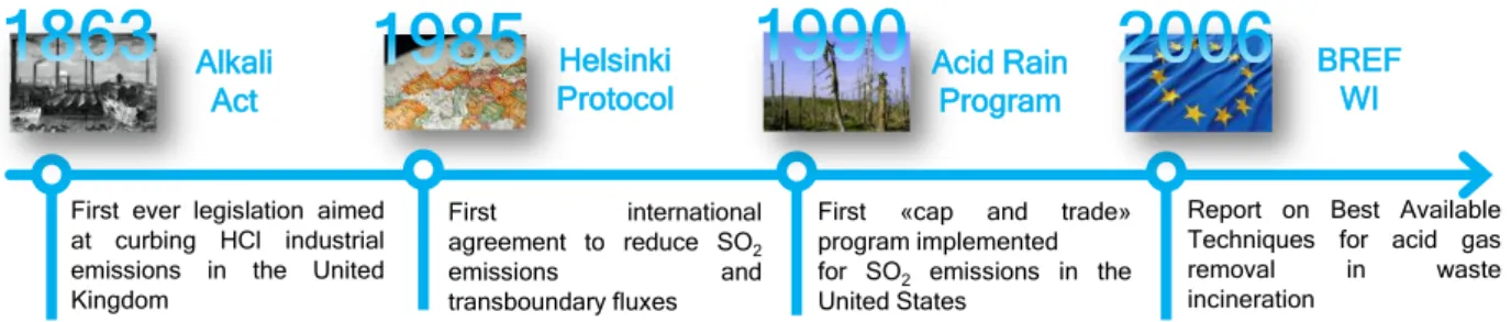
Tackling acid gas emissions has been one of the first challenges in the history of environmental protection and several environmental milestones have been put with reference to acid gases (Figure 1.5). Actually, HCl has been the first major pollutant to be object of a pollution control legislation. The Leblanc process, the earliest industrial process for the production of soda ash – a crucial chemical in the glass, textile, soap and paper manufacturing –, generated significant amounts of HCl, which were simply vented into the atmosphere. In order to target these noxious emissions, in 1863 the British Parliament passed the so-called Alkali Act, a law imposing that no more than 5% of the hydrochloric acid produced by soda plants could be vented to the atmosphere (Radojevic and Bashkin, 2006).
Figure 1.5. Some key events in the history of acid gas emission control.
Later, with the exponential growth of industrial production in the late XIX and early XX century, the soaring energy demand of the Western world was satisfied with increasing coal burning (Tertzakian, 2007), resulting in spiking SO2 emissions and consequent acid raining. As mentioned
in section 1.2, the first scientific observations about acid rain damages in Scandinavia in the 1960s First ever legislation aimed
at curbing HCl industrial emissions in the United Kingdom
First international agreement to reduce SO2 emissions and transboundary fluxes
First «cap and trade» program implemented for SO2 emissions in the United States
Report on Best Available Techniques for acid gas removal in waste incineration Alkali Act Helsinki Protocol Acid Rain Program BREF WI
15
raised global awareness on the issue, evidencing that pollution does not respect regional or national boundaries and atmospheric contaminants can undergo long-range transport. This leaded to the ratification of the international Convention on Long-Range Transboundary Air Pollution (1979) in Helsinki, which obligated the signatory countries to curb SO2 emissions. A decade after, the U.S.
EPA Acid Rain Program (1990) introduced the first emissions trading scheme in history, a market-based initiative aimed at promoting efforts in reducing SO2 emissions. Thanks to a combination of
worldwide political will and efficient technological solutions, the global emissions of sulfur dioxide have been steadily declining since the 1980s (Smith et al., 2011).
Flue gas cleaning systems currently implemented in power plants generate emissions that are 4-5 orders of magnitude lower than before environmental legislation against acid gases was conceived (Damgaard et al., 2010). The chemical principle behind the vast majority of technologies for the abatement of SO2, HCl and HF is the acid-base neutralisation:
𝐵𝑎𝑠𝑒 + 𝐴𝑐𝑖𝑑 → 𝑆𝑎𝑙𝑡 + 𝑊𝑎𝑡𝑒𝑟 1.3
Putting the acid gaseous pollutants in contact with a basic reactant generates a salt, either in liquid or solid form, thus removing the acid compounds from the flue gas. Neutralisation can be performed by injecting in the flue gas a basic solution (wet scrubbing) or a powdered basic solid sorbent (dry scrubbing), as detailed in chapter 2. In spite of the apparent simplicity of equation 1.3, acid gas neutralisation is a complex process, encompassing a stunning richness of chemical reaction engineering principles, and research is still needed to grasp a fundamental understanding of the involved phenomena and perform a fully aware process optimisation (see the research needs listed in chapter 4).
16
2 Acid gas abatement in Waste-to-Energy plants: state of the
art
2.1 Overview of air pollution control in the waste incineration sector
The thermal treatment of waste plays a relevant role even in the current paradigm of circular economy (European Commission, 2015), by contributing to landfill diversion (Nizami et al., 2016) and by guaranteeing energy recovery from those wastes for which recycling would be technically and economically unfeasible (Arena, 2015). The emission of pollutants typically related to the combustion of wastes is the main environmental drawback of a waste-to-energy (WtE) process (Ouda et al., 2016). However, properly operated plants can greatly reduce the load of pollutants emitted to atmosphere (Wojdyga et al., 2014).
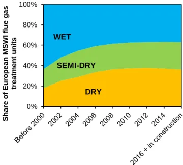
As mentioned in section 1.1, acid gases are typical pollutants in the flue gas emitted by waste combustion processes. Historically, acid gas treatment has been implemented by means of wet scrubbers, i.e. washing flue gas with basic solutions, taking advantage of both the high water solubility and acid/base reactivity of acid pollutants (Damgaard et al., 2010). In the last decades, the traditional wet processes have been increasingly replaced by the cheaper dry treatments, based on the injection of solid reactants in the flue gas. Surveying data from national environmental agencies, utility companies and industry consortiums (see Dal Pozzo et al., 2016), the market shares of wet, dry and semi-dry acid gas treatment systems over time in Europe were reconstructed in Figure 2.1, showing the unambiguous positive trend for the dry and semi-dry processes.
The basic scheme for dry acid gas removal is the so-called dry sorbent injection (DSI). It consists in the direct injection of a powdered basic sorbent (typically, calcium hydroxide or sodium bicarbonate, as detailed in section 2.2 and 2.3 respectively) in the flue gas ductwork, downstream of the air preheater and upstream of a dedusting equipment, such as an electrostatic precipitator (ESP) or a fabric filter, which collects the solid residues generated by acid gas neutralisation. When a fabric filter is used as dedusting equipment, the injected sorbent powders get captured by the filter bags, forming a filter cake which acts as a fixed bed reactor towards the flowing acid gases, actually incrementing the performance of the system.
Figure 2.1. Market shares of wet, semi-dry and dry acid gas treatment units in European WtE plants.
0% 20% 40% 60% 80% 100% Sh a re o f Eu ro p e a n MSW I fl u e g a s tr e a tm e n t u n its WET SEMI-DRY DRY
17
The advantages attracting the interest of plant operators and technology suppliers towards dry methods are, mainly, i) lower capital and maintenance costs due to lower equipment complexity; ii) easier and cheaper handling of solid residues compared to the wastewater generated by wet methods; iii) avoidance of “rain-out” issues at stack due to the condensation of wet flue gas.
The downside of dry methods is the intrinsic lower removal efficiency of gas-solid reactions when compared to gas-liquid reactions (Vehlow, 2015). This generally leads to the feed of solid reactant in relevant stoichiometric excess. Therefore, improving the removal efficiency to sorbent consumption ratio is a paramount target, pursued by the novel design choices illustrated in section 2.4 and by renewed efforts in enhanced process modelling (see section 4.2).
2.2 Solid sorbents for acid gas removal: Ca-based sorbents
Calcium-based sorbents have been the first powders to be considered for dry acid gas removal. Earlier approaches focused on the use of raw limestone (chemically, calcium carbonate, CaCO3) to
tackle HCl and SO2 emissions at high temperature, directly in the combustion chambers of
coal-fired or WtE plants (Petrini et al., 1979). Then, industrial interest quickly shifted towards calcium hydroxide, Ca(OH)2, the product of the calcination and subsequent hydration of limestone.
Commonly known also as hydrated lime or slaked lime, Ca(OH)2 is more reactive than calcium
carbonate, mainly because of the increased basic strength (Foo et al., 2016) and the higher porosity (Weinell et al., 1992).
Calcium hydroxide is generally assumed to react with HCl according to the following reaction:
𝐶𝑎(𝑂𝐻)2+ 2 𝐻𝐶𝑙 → 𝐶𝑎𝐶𝑙2+ 2 𝐻2𝑂 2.1
although relevant studies (Allal et al., 1997; Bodénan and Deniard, 2003; Bogush et al., 2015) point out that the actual stable solid product of HCl removal by Ca(OH)2 is calcium hydroxychloride
(CaOHCl), formed via partial chloridisation:
𝐶𝑎(𝑂𝐻)2+ 𝐻𝐶𝑙 → 𝐶𝑎𝑂𝐻𝐶𝑙 + 𝐻2𝑂 2.2
This topic will be explored in chapter 5.
Towards other acid gases, Ca(OH)2 reacts as follows:
𝐶𝑎(𝑂𝐻)2 + 2 𝐻𝐹 → 𝐶𝑎𝐹2+ 2 𝐻2𝑂 2.3
𝐶𝑎(𝑂𝐻)2+ 𝑆𝑂2 → 𝐶𝑎𝑆𝑂3+ 𝐻2𝑂 2.4
At the typical operating temperatures for acid gas removal, calcium sulphite (CaSO3) further
oxidises to calcium sulphate (anhydrite):
𝐶𝑎𝑆𝑂3+1
2𝑂2 → 𝐶𝑎𝑆𝑂4
2.5
Conversion to sulphate is generally incomplete and both sulphite and sulphate can be found in the reaction products (Bodénan and Deniard, 2003).
In addition, the undesired interaction between Ca(OH)2 and the carbon dioxide in flue gas cannot be
neglected:
𝐶𝑎(𝑂𝐻)2+ 𝐶𝑂2 → 𝐶𝑎𝐶𝑂3+ 𝐻2𝑂 2.6
Although carbon dioxide shows only limited acidic behaviour, its concentration in combustion flue gases is 3-4 orders of magnitude higher than HCl or SO2, hence up to 30% of the injected hydrated
18
lime can be subtracted to useful acid gas removal by competing carbonation (Antonioni et al., 2014).
When in-duct injection of hydrated lime takes place at high temperatures (> 400 °C, Gullett et al., 1992), calcium hydroxide is dehydrated to quicklime (calcium oxide, CaO):
𝐶𝑎(𝑂𝐻)2 → 𝐶𝑎𝑂 + 𝐻2𝑂 2.7
Calcium oxide presents higher porosity and specific surface area than calcium hydroxide, but its prolonged exposure to heat can trigger severe sintering (see paragraph X).
Figure 2.2. Gas-solid reaction according to the shrinking core model.
Kinetics and mass transfer phenomena involved in the dry sorption of acid pollutants by Ca(OH)2
will be thoroughly discussed in chapter 6. Here, in order to understand the conceptual framework behind the design of dry acid gas treatment systems (paragraph 2.4), the mechanisms governing the gas-solid reaction between Ca(OH)2 and acid gases can be simplified according to the so-called
shrinking core model (Levenspiel, 1998). Chemical reaction takes place at the interface between gas
and sorbent particles, where a shell of solid products (product layer) start accumulating. As reaction proceeds, the reacting particle gets consumed and shrinks, while product layer thickness increases (Figure 2.2). Consequently, acid gas sorption is mainly controlled by kinetics in the first seconds and by diffusional limitations afterwards.
The ideal range of temperatures for Ca(OH)2 injection lays between 120 and 160 °C (Dal Pozzo et
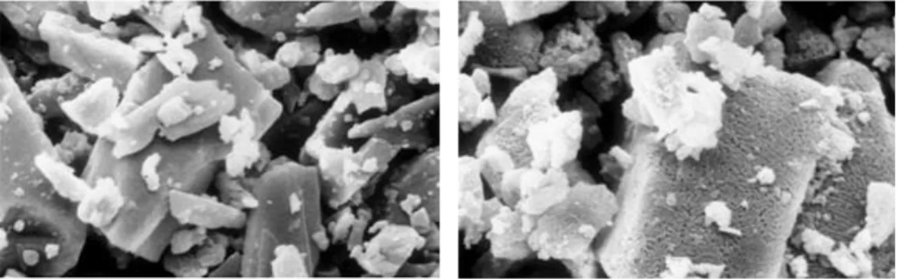
al., 2016), with improved efficiency as temperature decreases, because – while the water content in the flue gas remains constant – relative humidity (RH) increases (Harriott, 1990). The promoting effect of RH on the reactivity of Ca-based sorbents can be explained with reference to the shrinking core model: as sketched in Figure 2.3, adsorbed water can induce a rearrangement of the crystalline structure of the product layer, liberating new surface for reaction. Fonseca et al. (1998) advanced this hypothesis by comparing SEM images of lime reacted with HCl in dry or wet environment and Bausach et al. (2006) provided AFM imaging proving water-induced rearrangement of sulfate-based product layers.
sorbent particle
unreacted core product layer
19
Figure 2.3. Product layer formed a) in dry gas conditions, b) in wet gas conditions.
The solid residues of acid gas abatement by Ca(OH)2 are generally known as calcium-based waste
(CBW) or residual calcium chemicals (RCC). RCC are a mixture of the products of reactions 2.2, 2.3, 2.4, 2.5 plus unreacted calcium hydroxide. In addition, since they are usually collected by the first dedusting equipment in the flue gas cleaning line of a WtE plant, RCC are mixed with fly ash coming from the combustion chamber and activated charcoal injected for dioxine and furans adsorption.
Although several research projects have recently been started up with the aim of exploring recycling routes for RCC (Margallo et al., 2015), the actual fate of RCC across Europe is the disposal in landfills for hazardous materials or in underground storage sites (ISWA, 2008).
2.3 Solid sorbents for acid gas removal: Na-based sorbents
The use of sodium carbonate (Na2CO3) as acid gas removal agent was first explored in the 1980s
(Mocek et al., 1983; Kimura and Smith, 1987) and became a widespread approach in WtE plants in the mid-1990s (Vehlow, 2015), when Solvay S.A. marketed the so-called NEUTREC process consisting in the injection of NaHCO3 in flue gas and its subsequent collection by means of a fabric
filter or electrostatic precipitator.
When dry NaHCO3 is injected into the hot flue gas duct, it quickly decomposes to Na2CO3 via the
reaction:
2 𝑁𝑎𝐻𝐶𝑂3 → 𝑁𝑎2𝐶𝑂3+ 𝐻2𝑂 + 𝐶𝑂2 2.8
The thermal decomposition is an almost instantaneous and complete process at temperature higher than 130 °C (Hartman et al., 2013). Nonporous bicarbonate particles release water vapour and carbon dioxide, turning into porous sodium carbonate (see Figure 2.4). Then, sodium carbonate reacts with the acid gases according to the following schemes:
𝑁𝑎2𝐶𝑂3+ 2 𝐻𝐶𝑙 → 2 𝑁𝑎𝐶𝑙 + 𝐻2𝑂 + 𝐶𝑂2 2.9
𝑁𝑎2𝐶𝑂3+ 𝑆𝑂2+1
2𝑂2 → 𝑁𝑎2𝑆𝑂4+ 𝐶𝑂2
2.10
𝑁𝑎2𝐶𝑂3+ 2 𝐻𝐹 → 2 𝑁𝑎𝐹 + 𝐻2𝑂 + 𝐶𝑂2 2.11
Thermal decomposition, sometimes referred as thermal activation (Brivio, 2007) in order to highlight its role in triggering reactivity towards acid gases, is a crucial step in generating a highly porous material.
20
Figure 2.4. SEM images of: a) raw sodium bicarbonate, b) sodium carbonate obtained via reaction 2.8
(source: Kong and Davidson, 2010).
The kinetics of acid gas sorption by Na2CO3 is knowingly higher than that of Ca-based sorbents
(Duo et al., 1996; Antonioni et al., 2014; Vehlow, 2015). Although scholarly literature regarding gas-solid reactions between Na2CO3 and acid pollutants is limited (mainly due to the fact that
Na-based acid gas sorption is patented), the higher performance of Na2CO3 when compared to Ca(OH)2
might be ascribed to an higher intrinsic chemical reaction rate and a lower volume expansion associated with acid gas neutralisation.
In particular, volume expansion of the solid phase during sorption is a critical factor limiting the total molar conversion of sorbent particles. For example, with reference to reaction 2.1, the molar volume of CaCl2 is larger than that of Ca(OH)2 and, thus, the reaction causes an expansion in the
pores of the solid, eventually filling the voids within sorbent particles before 100% conversion is reached. The theoretical final conversion due to the complete filling of intraparticle voids (Simons and Garman, 1986) can be expressed through eq. 2.12:
𝑋𝑠,𝑚𝑎𝑥=
𝜀𝑝
(1 − 𝜀𝑝)(𝛼 − 1) 2.12
where εp is the initial void fraction of the sorbent and α the volumetric expansion factor, defined as
the ratio of the molar volume of the solid product to the molar volume of the solid reactant.
Figure 2.5 shows the maximum theoretical conversion of sorbent exposed to HCl as a function of its initial void fraction and the volumetric expansion factor associated with chloridisation. The conversion of Ca(OH)2 to anhydrous CaCl2 entails an α = 1.54, while, if the CaCl2 product is
assumed to be in dihydrate form, α = 2.39. Significantly less volume expansion (α = 1.29) is associated with Na2CO3 chloridisation. This means that, while a particle of Na2CO3 with a porosity
εp = 0.3 can be in theory entirely converted to NaCl, a particle of Ca(OH)2 with the same starting
porosity can only reach a maximum theoretical conversion of 80% if the product is anhydrous CaCl2 and 30% if the product is CaCl2 dihydrate. Further details about the importance of the issue
of incomplete conversion in formulating a phenomenological model for Ca(OH)2-based acid gas
removal will be given in chapter 6. As for the moment, it is sufficient to state that the absence of theoretical limitations to complete conversion is one of the main advantages of Na-based sorbents over Ca-based ones.
21
Figure 2.5. Maximum theoretical conversion for sorbent chloridisation as a function of its initial void
fraction and the volumetric expansion associated with the specific reaction (eq. 2.12).
The typical range of temperatures for NaHCO3 injection in the flue gas is 140-300 °C (Dal Pozzo et
al., 2016), with slight improvement of performance as temperature increases due to kinetic effects. The residues of acid gas neutralisation by NaHCO3 are known as sodium-based waste (SBW) or
residual sodium chemicals (RSC) and contain the products of reactions 2.9, 2.10 and 2.11. Unlike RCC, RSC benefits from a market-ready solution for their recycling, the brine recovery process performed by Solvay S.A. in two dedicated plants, in France and Italy (Brivio, 2005). The precondition is the separate collection of RSC and fly ash, which can be achieved by installing a dedusting equipment upstream of the NaHCO3 injection point. The process for recycling RSC is
described by several sources (Brivio, 2005; Ninané et al., 1995; ISWA, 2008; Solvay, 2014). The RSC are mixed with water in order to obtain a saturated brine of the soluble salts (NaCl, Na2SO4,
Na2CO3), while the heavy metals and impurities precipitate. Additives such as sodium sulphide,
sodium silicate and iron chloride are usually added in this phase. The brine is then filtered in a filter press, and further purified by activated charcoal and ion exchange resins. The depurated brine is suitable for use as a raw material in the sodium carbonate production (BREF LVIC-S, 2007).
2.4 Review of the latest developments in dry sorbent injection technologies
As shown in section 2.1, dry treatment systems are increasingly valued as reliable and cost-efficient solutions for acid gas control in the waste incineration sector. However, European recommendation on best available techniques (BAT) for flue gas cleaning in WtE plants, collected in a dedicated BAT reference document, was released more than 10 years ago (BREF WI, 2006). Therefore, the document mentions only the simple DSI as state-of-the-art dry treatment technique, providing a narrow and incomplete representation of the wide gamma of dry acid gas removal solutions currently available on the market. The following overview, based on the technical Italian paper by Dal Pozzo et al. (2016), aims at filling the gap by concisely sketching the main innovations introduced to couple the compliance to stricter emission limit values (Directive 2010/75/EU) with cost optimisation. Some of the systems described hereunder are sketched in Figure 2.6.
0 0.1 0.2 0.3 0.4 0.5 0.6 0.7 0.8 0.9 1 0 0.1 0.2 0.3 0.4 0.5 0.6 0.7 Xs ,m a x Ɛp Na2CO3 --> NaCl Ca(OH)2 --> CaCl2 Ca(OH)2 --> CaCl2 x 2H2O
𝑁𝑎2𝐶𝑂 → 2 𝑁𝑎𝐶𝑙 𝐶𝑎(𝑂𝐻)2→ 𝐶𝑎𝐶𝑙2 𝐶𝑎(𝑂𝐻)2→ 𝐶𝑎𝐶𝑙2 2𝐻2𝑂
22
DSI with pre-conditioning. At the typical operating temperatures of DSI systems (120-180 °C), even flue gases with relatively high water content (10-15 vol. %) such as the ones deriving from waste combustion present values of relative humidity only at 1-5%. Therefore, considering the link between RH and the acid gas sorption performance of Ca-based sorbents, further flue gas humidification is required if a European WtE plant has to rely only on a single stage injection of Ca(OH)2 in order to remove acid gases down to the emission limit values. Pre-conditioning is
performed by installing a quenching tower upstream of the lime injection point: spraying pulverised water in the ductwork simultaneously increases the water content of the flue gas and decreases its temperature, rising its relative humidity. DSI units with pre-conditioning, fed with Ca(OH)2, are
actually able to comply with the limits set by Directive 2010/75/EU and, for instance, have been the adopted solution in the recently-built MSWIs in Bialystok and Bydgoszcz (Poland). In order to reduce the consumption of fresh lime, a common approach is to recirculate part of the RCC collected by the fabric filter.
Furnace sorbent injection (FSI). Another alternative to simple DSI is the sorbent injection directly performed in the combustion chamber, in order to take advantage of the higher chemical reaction rate achievable at high temperatures (850-1000 °C). The drawback is that high temperatures also trigger sorbent sintering, drastically reducing the active surface area of reactant particles.
While historically FSI was the first approach at acid gas removal by limestone, as mentioned in paragraph 0, it has been recently revaluated after the successful testing of a dolomitic sorbent – commercially known as Depurcal – in three WtE plants in Northern Italy since 2011 (Biganzoli et al., 2015). The adopted sorbent is a mixture of calcium hydroxide and magnesium oxide (Ca(OH)2∙MgO, Ca/Mg ratio > 1.4) resulting from the calcination of dolomite. Upon furnace
injection, Depurcal undergoes a thermal decomposition similar to the one of NaHCO3 in DSI,
releasing hydration water and developing a microporous structure. Unlike regular Ca-based sorbents, Depurcal does not suffer significant sintering. Indeed, while acid gas sorption is mainly performed by the calcium fraction of Depurcal, the almost inert MgO acts as a structural agent, preventing the collapse of the pores thanks to its high resistance to sintering (the concept will be expanded in section 3.3 with reference to solid sorbents for CO2 capture).
Biganzoli et al. (2015) observed that FSI with Depurcal allowed an average reduction of the loadings of SO2 and HCl to the flue gas cleaning line of 25 and 70%, respectively, and resulted
particularly helpful in attenuating short-time spikes of acid gas emissions.
Spray dryer absorption (SDA). SDA equipments are used to further enhance the reactivity of Ca-based sorbents thanks to the promoting effect of water. In these systems, Ca(OH)2 is first suspended in water to produce a milk of lime with a 20-25 wt. % concentration (Gambarè, 2013) and then the obtained basic slurry is sprayed in a scrubber vessel. The contact between the flue gas and the pulverised slurry promotes the sequestration of acid pollutants via mass transfer from the gas phase to the liquid phase and subsequent chemical reaction. At the same time, the water content in the slurry evaporates, leading to the formation of solid residues.
The main parameter governing the process is the so-called approach to saturation temperature (AST), defined as the difference between the temperature of the inlet flue gas and its adiabatic saturation temperature (Harriott et al., 1991). SDA performance increases when AST decreases (i.e., when RH increases), but at the same time a low AST implies problems in terms of acid condensation in the vessel and agglomeration of the filter cake on the bags of the fabric filter downstream. Optimal values of AST lie between 10 and 15 °C (Srivastava and Jozewicz, 2001).
23
The semi-dry approach of SDA systems shares the advantages of a typical wet process (viz. low consumption of reactants and high removal efficiency), without the drawback of generating liquid residues. Nonetheless, in order to avoid costs and complications related to slurry preparation, the most recent design practices tend to separate the injections of water and lime, thus resorting to the aforementioned DSI with pre-conditioning or to the so-called CDS systems.
Circulating dry scrubbing (CDS). CDS are semi-dry solutions based on Ca(OH)2 injection which
are aimed at achieving high acid gas removal efficiency with the lowest sorbent consumption, by increasing the residence time of solid reactants in the system. They can be sorted in two categories: circulating bed scrubbers and systems with humidified solids recirculation.
In the former, water and lime are separately introduced inside a vertical reactor, designed to create a fluidised bed. The reactor is aimed at guaranteeing both high relative humidity and high solid residence time. Downstream, part of the solid residues of the process, collected by a fabric filter, are recirculated back to the reactor, in order to increase the sorbent-to-acid gas ratio.
Conversely, systems based on the recirculation of humidified solids recall the essential design of DSI (for example, the reactor is often a simple vertical conduit), but focus on an optimised recirculation section as the key factor to enhance performance.
As a matter of fact, the bare recirculation of RCC “as is”, adopted in several DSI units, has a strong, intrisic limitation: partially reacted lime particles exhibit a noticeably lower reactivity than fresh Ca(OH)2, because the shell of solid product covering the unreacted core of sorbent particles
remarkably hinders the diffusion of acid pollutants towards reaction interface.
In order to promote the reactivity of recirculated lime, several technology suppliers propose patented recirculation systems aimed at “reactivating” the partially reacted sorbent in two ways:
mechanical reactivation – the action of a mixing cochlea induces the fracture of product layers on sorbent particles via attrition and grinding between particles.
rehydration – pulverised water is sprayed in order to wet the partially reacted lime, triggering a rearrangement in the product layer (the effect already shown in Figure 2.3). Lime is a hygroscopic material and adsorbs water, which in turn interacts with the product layer, exposing fresh lime surface. A similar effect can be obtained without spraying water, but employing a stream of steam, generated e.g. by using the heat of flue gas exiting the combustion chamber.
Two-stage dry treatment systems. Lastly, among the most novel solutions for dry acid gas removal, the double reaction/double filtration dry treatment system (Acquistapace, 2014) – adopted since 2006 in some Italian WtE plants – consists in two consecutive stages of sorbent injection and dedusting with a fabric filter. This configuration, which is essentially the connection in series of two DSI units, has the twofold target of increasing the overall removal efficiency and significantly lowering operating costs in comparison with usual single stage approaches. A detailed economic analysis of the savings achievable with a two-stage acid gas removal system is presented in chapter 7.
In the typical two-stage system, the first stage is fed with the cheaper sorbent (i.e., hydrated lime) and has the role to remove most of the acid gas loading, while the more reactive sodium bicarbonate is injected in the second stage, in order to abate the residual acid pollutants down to the set-point for their concentrations at stack. Furthermore, by acting downstream of a fabric filter, the second stage generates RSC which are not contaminated with fly ash and thus recyclable.
Anyway, the two-stage configuration, besides offering a useful redundancy, allows operating versatility in terms of choice of sorbents. It is also possible to operate with two Ca-based stages,
24
like in the Runcorn WtE facility and in the hazardous waste incinerator in Grundon, both in the United Kingdom (de Greef et al., 2013), or with two Na-based stages, in a set-up potentially able to further reduce operating costs (Guglielmi et al., 2014). In contrast, the high space requirements and the design focused on the removal of high loads of acid pollutants make the two-stage system a viable solution mainly for mid-to-large WtE plants (> 400 t/day of treated waste).
25
Figure 2.6. Some dry acid gas removal configurations: a) spray dryer absorption; b) circulating dry
scrubber; c) furnace sorbent injection + dry sorbent injection w/ pre-dusting; d) system with rehydrated sorbent recirculation; e) two-stage dry treatment system.
Equipment CC Combustion chamber FF Fabric filter Streams W Water HL Hydrated lime QL Quicklime DP Depurcal SB Sodium bicarbonate SR Solid residues
FF
FF
FF
FF
FF
FF
FF
SR
SR
SR
SR
SR
SR
HL
HL
HL
QL
W
W
W
DP
SR
SB
BS
flue gas
flue gas
flue gas
a)
b)
c)
d)
e)
CC
CC
26
3 Carbon capture with solid sorbents: state of the art
3.1 The concept of carbon capture and storage
Despite the scientific and politic awareness of the threats of climate change mentioned in section 1.4, meaningful actions to limit CO2 emissions worldwide collide with the tight bond between CO2
generation and energy production. Even if renewable energies are making remarkable progress, fossil fuel consumption worldwide is still increasing year-by-year (IEA, 2016). Coal, oil and natural gas are still expected to play a major role in the world energy mix in the near- to mid-term future (McKinsey & Company, 2008).
Large stationary sources like coal-fired power plants are the main contributors to CO2 emissions
(Choi et al., 2009) and, therefore, the deployment of industrial CO2 capture and storage (CCS)
technologies could be a promising approach to achieve a meaningful reduction of CO2 emissions in
the near term (MacDowell et al., 2010). The CCS process consists in capturing waste CO2 from
large point sources and disposing of it in safe storage sites, like underground geological formations. Therefore, CCS has to be seen as an interim solution, a direct emissions mitigation option to buy time for a 50-year transition away from fossil fuels (Stuart Haszeldine, 2009).
Figure 3.1. The life-cycle chain of fossil fuel use with CCS employment. CO2 is separated and captured at power plants and stored in porous rocks deep below ground. Source: Stuart Haszeldine, 2009.
3.2 Approaches to CO2 capture
Three methods of CO2 capture are currently under study:
Post-combustion capture. CO2 is removed from the flue gas of the combustion process
with an end-of-pipe approach, like for the acid gases (chapter 2). Post-combustion schemes are attractive for retrofitting existing power plants. Here, the major challenge for separation technologies is obtaining a pure (> 95 vol. %), concentrated stream of CO2 from the
typically dilute (< 15 vol. %) flue gas, without excessive energy penalty (Leung et al., 2014).
27
Pre-combustion capture. In this approach, the fuel (e.g., coal or natural gas) is pre-treated before combustion. For example, coal might be gasified to produce a syngas consisting of CO and H2. Then, the syngas undergoes water gas shift reaction with steam in order to form
more H2 while CO is converted to CO2 (Rahman et al., 2017). The CO2 concentration in the
gas stream is generally rather high (20-30%, Boon et al., 2016), facilitating the separation needed to obtain a hydrogen-rich fuel gas.
Oxyfuel combustion. In oxyfuel combustion, the fuel is combusted in nearly pure O2,
instead of air. Therefore, the amount of nitrogen present in the flue gas is drastically reduced and the main exhaust gases are CO2 and H2O. The water content is easily removed by
condensation, leaving a pure CO2 stream which is suitable for compression, transport and
storage (MacDowell et al., 2010).
Several technological solutions have been explored to realise pre- or post-combustion CO2 capture
processes, as an emanation of the diverse research programmes financed by public institutions and private companies in the last years.
Absorption, i.e. the use of a liquid sorbent to remove CO2 from the flue gas, has been the first
separation process to be studied, with the first patent regarding amine scrubbing dating back to 1930 (Rochelle, 2009). Currently, monoethanolamine (MEA) is the reference solvent used in CO2
absorption pilot plants, showing CO2 separation efficiencies > 90% (Aaron and Tsouris, 2005),
while other solvents such as piperazine (Zhang et al., 2016) and anion-functionalised ionic liquids (Macfarlane et al., 2014) are catalysing novel research efforts.
Membranes constitute another viable option for selective CO2 separation. Current ceramic or
polymeric membrane can achieve CO2 separation efficiencies in the range 80-85% (Leung et al.,
2014), but performances are strongly affected by CO2 concentration. Breakthrough developments in
enhancing CO2 performance and solving fouling issues are needed to harness the full potential of
this technology (Brunetti et al., 2010).
Chemical looping combustion (CLC) is based on the use of a metal oxide as oxygen carrier in order
to obtain a CO2-rich flue gas. During CLC, the metal oxide is reduced to metal while the fuel is
being oxidised to CO2 and water. Hence, like in oxyfuel combustion, a pure CO2 stream can be
easily produced via condensation. The metal is reconverted to metal oxide in a dedicated oxidation stage and recirculated back in the process. Several low-cost metal oxides, such as CuO (Imtiaz et al., 2012), Fe2O3 (Yüzbasi et al., 2016) and Mn2O3 (Hosseini et al., 2015), have been demonstrated
suitable for CLC applications, but operating experience at pilot scale is still lacking.
Adsorption processes, in contrast to absorption, make use of solid sorbents to physically or
chemically bind CO2. Sorbent as diverse as activated carbon (Xing et al., 2012), zeolites (Bae et al.,
2013), metal-organic frameworks (Bae and Snurr, 2011), hydrotalcites (Coenen et al., 2016) and metal oxides (Wang et al., 2014) have been tested extensively. Adsorbed CO2 can be recovered via
desorptive regeneration of the sorbent, by swinging pressure or temperature of the system (Leung et al., 2014). A particularly promising scheme is represented by the carbonate looping technology described in the following section.
28
Table 3.1. Summary of advantages and disadvantages of main CO2 separation technologies. Separation
technology
Advantages Disadvantages References
Absorption - Most mature technology (the basic principle of the process was patented in 1930)
- Regeneration by heating and/or depressurisation - MEA-based absorption mature process for CO2
separation
- Important industrial players actively engaged in research and deployment of this technology - New promising schemes based on piperazine as
highly reactive CO2 solvent are under study
- Significant energy penalty associated with solvent regeneration
- High solvent flow rates required to achieve high rate of CO2 capture, given the low CO2 partial
pressure in the flue gas
- Generation of wastewater (exhaust solvent) - Fugitive solvent emissions rise environmental
concerns
Aaron and Tsouris (2005) Rochelle (2009)
MacDowell et al. (2010)
Adsorption - Use of abundant and inexpensive natural sorbents (e.g. limestone, dolomite)
- Potential higher cost-efficiency compared to amine scrubbing
- Important synergy with the cement industry - Process successfully tested at demonstration scale
in Spain and Germany
- Alternatives to Ca-based sorbents for CO2 capture
at low, intermediate and high temperature currently under study (e.g. Na2CO3, MgO, Li4SiO4, etc.)
- High energy penalty for CO2 desorption
- Ca-based sorbents are vulnerable to decay in capture capacity over repeated cycling
- Competitive reactions with acid gases (HCl, SO2)
may consume relevant amounts of the sorbent, if separate desulfurisation is not employed
Blamey et al. (2010) Dean et al. (2011)
Boot-Handford et al. (2014)
Membrane separation
- Several membrane classes currently researched (inorganic membranes, polymeric membranes, facilitated liquid membranes)
- Successful operational experience in the separation of other gases
- At least a 10-fold higher CO2 permeance than
current commercial membranes is required to provide enough driving force to the process - Reliability concerns due to several operational
problems (e.g. low fluxes, fouling, etc.)
Brunetti et al. (2010) D’Alessandro et al. (2010) Merkel et al. (2010) Chemical looping combustion
- Like for the oxyfuel approach, CO2 is the main
combustion process, thus avoiding energy intensive separation from N2
- Wide portfolio of oxygen-carriers tested in literature for different combustion conditions
- No large scale operational experience to-date - Lack of information on CLC performances in
pressure
29
3.3 Perspective of carbonate looping in pre- and post-combustion CO2 capture
The carbonate looping concept for CO2 capture, first proposed by Shimizu et al. (1999), is based on
the reversible reaction between certain metal oxides and carbon dioxide to form metal carbonate. The most studied solid sorbent candidate is calcium oxide (CaO), which can be derived from natural limestone. Hence, the process is frequently referred to as Calcium Looping (Blamey et al., 2010). The reaction of interest is the following:
𝐶𝑎𝑂 + 𝐶𝑂2 ↔ 𝐶𝑎𝐶𝑂3 ∆𝐻298 𝐾0 = −178 𝑘𝐽 𝑚𝑜𝑙−1 3.1
The carbonation reaction is exothermic and the reverse reaction, known as calcination, is endothermic. Carbonation is characterised by a rapid initial rate followed by an abrupt transition to a sluggish regime, whereas calcination typically proceeds rapidly to completion in minutes over a wide range of conditions (Silaban and Harrison, 1995).
Calcium looping has been first conceived for post-combustion CO2 capture. The simplified
post-combustion process flow diagram is shown in Figure 3.2. In one vessel, the carbonator, the carbonation reaction removes CO2 from a flue gas (e.g., the exhaust gas from coal combustion),
forming solid CaCO3. CaCO3 is then transferred to a second reaction vessel, the calciner, where it is
heated to trigger the reverse calcination reaction, releasing CO2 and regenerating the CaO sorbent,
which is recycled back into the carbonator. A circulating fluidised bed reactor (CFB), which is a mature technology at the large scale, is the typical configuration proposed for both carbonator and calciner (MacDowell et al., 2010).
Figure 3.2. Post-combustion carbonate looping. Source: MacKenzie et al. (2007).
Whilst originally introduced for post-combustion capture applications, carbonate looping is also suitable in pre-combustion capture schemes aimed at the selective production of hydrogen from hydrocarbons (coal and biomass gasification, methane reforming, etc.). These approaches,
30
commonly referred to as sorbent-enhanced reforming (SER; MacDowell et al., 2010), take advantage of the carbonation of sorbent for the twofold goal of separating CO2 and promoting H2
generation. An explicative application is the sorbent-enhanced methane steam reforming (Broda et al., 2012). In a dedicated hydrogen production plant, the methane steam reforming reaction, performed over a Ni catalyst, proceeds as follows:
𝐶𝐻4+ 𝐻2𝑂 ↔ 𝐶𝑂 + 𝐻2 ∆𝐻298 𝐾0 = 206 𝑘𝐽 𝑚𝑜𝑙−1 3.2
and the effluent gas is further enriched in H2 thanks to the water gas shift reaction (over Fe or Cu
catalyst, depending on operating temperature; Newsome, 1980):
𝐶𝑂 + 𝐻2𝑂 ↔ 𝐶𝑂2+ 𝐻2 ∆𝐻298 𝐾0 = −41 𝑘𝐽 𝑚𝑜𝑙−1 3.3
By coupling CO2 sorption by CaO (reaction 3.1) with reactions 3.2 and 3.3, the equilibrium of the
overall process:
𝐶𝐻4+ 2 𝐻2𝑂 + 𝐶𝑎𝑂 ↔ 𝐶𝑎𝐶𝑂3+ 4 𝐻2 ∆𝐻298 𝐾0 = −1 𝑘𝐽 𝑚𝑜𝑙−1 3.4
is shifted on the product side, thus producing high-purity hydrogen.
As summarised in Table 3.1, the carbonate looping scheme boasts the potential to provide cost-effective CO2 capture. Sorbents derived from natural limestone are inexpensive and the process
economics appears particularly favourable when the exhausted reactants are considered as a feedstock for cement manufacturing (Dean et al., 2011). In addition, several researchers pointed out that the carbonate looping process might significantly reduce the efficiency penalty (i.e. the net decrease in the power efficiency of a thermoelectric plant caused by the CO2 capture and
compression process) when compared to the more mature amine scrubbing technology: the energy penalty associated with Calcium Looping have been estimated in the range 3-8% (Goto et al., 2013; Hanak et al., 2015), an extremely competitive figure compared to the 10-12% drop in efficiency estimated for MEA-based scrubbing (Xu et al., 2010; Hanak et al., 2014). These are the main reasons which have been driving a rapid evolution of post-combustion carbonate looping from the lab- and pilot- to demonstration-scale (Arias et al., 2013; Dieter et al., 2014). Furthermore, whereas calcium oxide is clearly the most studied carbonate looping sorbent, thriving research efforts are currently dedicated worldwide to the study of alternative sorbents, capable of operating at different temperature ranges or overcoming the intrinsic shortcomings of CaO (see sections 4.1 and 9.1), and the work presented in Part III of the thesis goes into that direction.