Ottimizzazione e miglioramento del comportamento a fatica di ponti a piastra ortotropa
270
0
0
Testo completo
(2)
(3) Z.H. QIAN. OTTIMIZZAZIONE E MIGLIORAMENTO DEL COMPORTAMENTO A FATICA DI PONTI A PIASTRA ORTOTROPA. Tesi, luglio 2010. DIPARTIMENTO DI INGEGNERIA CIVILE UNIVERSITA’ DEGLI STUDI DI ROMA “TOR VERGATA”. DOTTORATO DI RICERCA IN INGEGNERIA DELLE STRUTTURE E GEOTECNICA.
(4)
(5) DOTTORATO DI RICERCA IN INGEGNERIA DELLE STRUTTURE XXI CICLO UNIVERSITÀ DEGLI STUDI DI ROMA "TOR VERGATA". OTTIMIZZAZIONE E MIGLIORAMENTO DEL COMPORTAMENTO A FATICA DI PONTI A PIASTRA ORTOTROPA Tesi presentata per il conseguimento del titolo di Dottore di Ricerca in Ingegneria delle Strutture da. Zhonghui QIAN. Coordinatore del Corso di Dottorato Prof. Franco Maceri. Tutore del candidato Prof. Ing. Antonio Grimaldi Co-tutore Prof. Ing. Donato Abruzzese. Dipartimento di Ingegneria Civile Luglio 2010. ..
(6)
(7) ACKNOWLEDGEMENTS The author would like to express his most sincere gratitude and deepest appreciation to Prof. Donato ABRUZZESE, Prof. Antonio GRIMALDI and Ing. Sante CAMO, who spent much time to guide the investigation. Their guidance, insight, patience and encouragement not only help the author on this dissertation, but also regarding his professional career. They provided the author many chances to participate intensive courses and conferences, both in Italy and other countries. The author would like to express his great appreciation to Prof. Jianli YUAN for his continuous concern and guidance during the past years. The author would like to express his deep appreciation to the technician Fedinando MIELE and Dr. Lorenzo MICCOLI. Special thanks are given to Prof. Vincenzo Tagliaferri, Dr. Massimiliano Barletta, Ing. Daniele Carnevale and Ing. GIANLUCA for the collaboration of laboratory tests. The author would like to express his appreciation to Prof. Ben YEN, Prof. Richard SAUSE, Prof. John W. FISHER, Dr. Cheng CHEN, and Dr. Sougata ROY for their great help when he visited Lehigh University. The author would like to thank Dean Marina TESAURO, and Ms. Claudia FIORANI and Ms. Belinda CAPARRO for their continuous support when he arrived in Rome. The author also would like to thank all the faculty and staff of Department of Civil Engineering who helped him during his studies. Many thanks are given to Mr. Yan Chu FONG, Dr. Jun XIAO and many other friends for the encouragement and help during these years. Finally, the author would like to express his deepest thanks to his parents and his wife Beibei Liu for their constant and strong encouragement and support..
(8)
(9) TABLE OF CONTENTS 1. INTRODUCTION ............................................................................................................ 1 1.1 Historical Development of Analytical Methods and Design ............................................1 1.2 The Advantages of Orthotropic Deck in Bridge Engineering ..........................................4 1.3 Orthotropic Deck Plate in Bridge Structure .....................................................................6 1.4 Optimization Technologies ..............................................................................................8 1.5 Research Objectives .........................................................................................................9 1.5.1 Geometric optimization of orthotropic deck .............................................................9 1.5.2 Fatigue enhancement ...............................................................................................10. 2. ANALYSIS METHODS OF ORTHOTROPIC DECK ........................................ 15 2.1 Classical Theories...........................................................................................................15 2.1.1 Introduction of orthotropic plate theories ................................................................16 2.1.2 Orthotropic plate theory ..........................................................................................18 2.1.2.1 Determination of rigidities in various specific cases ........................................20 2.1.2.2 Application of the theory to the calculation of gridworks ................................24 2.1.3 The Pelikan-Esslinger Method ................................................................................27 2.1.3.1 Open rib of orthotropic deck ............................................................................28 2.1.3.2 Closed rib of orthotropic deck ..........................................................................32 2.1.3.3 The Pelikan-Esslinger method in AISC ............................................................36 2.2 Finite Element Methods .................................................................................................38 2.2.1 Advantages of FEM .................................................................................................39 2.2.2 Disadvantages of FEM ............................................................................................41 2.2.3 Application of FEM in orthotropic deck .................................................................41 2.3 Fatigue Behaviors ...........................................................................................................43 I.
(10) 3. INFLUENCES OF GEOMETRIC PROPERTIES TO ORTHOTROPIC DECKS ....51 3.1 Finite Element Analysis .................................................................................................54 3.1.1 Introduction .............................................................................................................54 3.1.2 Numerical modeling ................................................................................................55 3.1.2.1 Detailed dimensions .........................................................................................55 3.1.2.2 Boundary conditions .........................................................................................56 3.1.2.3 Load cases ........................................................................................................56 3.2 Deck Behaviors ..............................................................................................................57 3.2.1 Behaviors of deck plate ...........................................................................................58 3.2.2 Behaviors of diaphragm ..........................................................................................65 3.3 Influence of Cutout .........................................................................................................73 3.3.1 Introduction .............................................................................................................73 3.3.2 The four different shapes of cutout..........................................................................78 3.3.3 Results of Static analysis .........................................................................................80 3.3.3.1 The Stress performance in the diaphragm ........................................................80 3.3.3.2 The deflection and stress in the deck plate .......................................................86 3.3.4 Discussions ..............................................................................................................92 3.4 Influence of Bulkhead ....................................................................................................96 3.4.1 Introduction .............................................................................................................96 3.4.2 The four different models with or without bulkhead .............................................100 3.4.3 Results of Static analysis .......................................................................................102 3.4.3.1 Behaviors of the diaphragm............................................................................102 3.4.3.2 Behaviors of the deck plate ............................................................................ 114 3.4.4 Discussions ............................................................................................................121 3.5 Influence of Deck Plate ................................................................................................124 3.5.1 Introduction ...........................................................................................................124 II.
(11) 3.5.2 Thickness influence of the deck plate....................................................................126 3.5.3 Discussions ............................................................................................................130 3.6 Future research .............................................................................................................131. 4. FATIGUE EVALUATION OF ORTHOTROPIC DECK ................................. 135 4.1 Design Codes ................................................................................................................140 4.1.1 European codes......................................................................................................141 4.1.1.1 British standard (BS5400) ..............................................................................141 4.1.1.2 Eurocode 3 ......................................................................................................144 4.1.1.3 DNV offshore specifications ..........................................................................147 4.1.2 American specifications ........................................................................................150 4.1.3 Recommendations of IIW......................................................................................154 4.1.4 Japanese specifications ..........................................................................................158 4.1.5 Chinese codes ........................................................................................................160 4.1.6 Discussions ............................................................................................................161 4.2 Nominal Stress Approach .............................................................................................165 4.2.1 Fatigue cumulative damage law ............................................................................165 4.2.1.1 Linear fatigue cumulative damage law ...........................................................166 4.2.1.2 Nonlinear fatigue cumulative damage law .....................................................166 4.2.2 Traditional nominal stress approach ......................................................................168 4.2.2.1 Assumptions of nominal stress approach........................................................169 4.2.2.2 Traditional nominal stress approach ...............................................................169 4.3 Hot Spot Stress Approach ............................................................................................171 4.3.1 The definitions of the structural hot spot stress method ........................................171 4.3.2 Recent investigations of structural hot spot stress method ....................................176 4.3.3 Discussions ............................................................................................................178 III.
(12) 4.4 Method of Analysis ......................................................................................................179 4.4.1 Global model analyses of the orthotropic deck .....................................................179 4.4.1.1 Global model ..................................................................................................179 4.4.1.2 Results of global model analyses....................................................................180 4.4.2 Submodel analyses of the rib-to-deck plate connections.......................................180 4.4.2.1 Submodel ........................................................................................................180 4.4.2.2 Results of submodel analyses .........................................................................184 4.4.3 Structural hot-spot stresses ....................................................................................196 4.4.4 Three-step approach ..............................................................................................199 4.4.5 Conclusions ...........................................................................................................200. 5. FATIGUE ENHANCEMENT TECHNIQUES ..................................................... 205 5.1 Stress Methods .............................................................................................................207 5.1.1 Shot peening ..........................................................................................................207 5.1.2 Hammer peening ...................................................................................................209 5.1.3 Needle peening ......................................................................................................211 5.1.4 Ultrasonic impact treatment ..................................................................................212 5.1.5 Laser peening ........................................................................................................214 5.1.6 Fluid bed peening ..................................................................................................215 5.1.7 Discussions ............................................................................................................220 5.2 Geometric Methods ......................................................................................................222 5.2.1 Buur Grinding........................................................................................................222 5.2.2 TIG dressing ..........................................................................................................224 5.3. Fatigue Tests Applied FBP ..........................................................................................226 5.3.1 Material tests .........................................................................................................226 5.3.2 Surface treatment ...................................................................................................228 IV.
(13) 5.3.3 Fatigue tests ...........................................................................................................233 5.3.3.1 Loading spectrum ...........................................................................................233 5.3.3.2 Test results ......................................................................................................235 5.3.4 Discussions and conclusions .................................................................................239. 6. CONCLUSIONS AND RECOMMENDATIONS ................................................ 243 6.1 Conclusions ..................................................................................................................243 6.2 Recommendations ........................................................................................................245. REFERENCES .................................................................................................................. 247. V.
(14) VI.
(15) ABSTRACT Orthotropic deck bridges are widely used in bridge engineering, especially for long span bridges. Although orthotropic deck bridges have many advantages, it is found that they are sensitive to produce fatigue cracking under the repeating vehicle loading since there are a large number of welded connections in the deck structure. Among of these connections, rib-to-deck plate connection, rib-to-diaphragm connection and rib-to-diaphragm-to-deck plate (RDDP) connection are the three typical welded connections that are more sensitive to the fatigue cracking due to the high concentrated stress and high residual stress. Fatigue analysis of an orthotropic deck is a complex and uncertain process due to many factors which can influence the fatigue cracking. A state-of-the-art literature review of the fatigue codes/specifications was conducted to identify their advantages, disadvantages and limitations in this study. Meanwhile, the stress performances of a typical orthotropic deck were analyzed through Finite Element analysis (FEA) and, then, the fatigue resistance evaluation was carried out by the structural hot spot stress method. In addition, a fatigue improvement technique, the Fluid Bed Peening (FBP) was illustrated, and fatigue tests of the specimens treated by FBP were conducted in the laboratory. The primary two goals of this study are to analyze the stress performances of the orthotropic deck and to develop an approach for improving the fatigue behaviors through FE method and analytical techniques, by doing parametric studies of various geometric parameters and the structural hot spot stress method. Many FE models were developed in order to analyze the stress influences of cutout geometry, with or without bulkhead, and the thickness of deck plate. The different applied loadings, which to simulate the different vehicle locations on the pavement, were used in order to obtain the maximum stress range. Then, submodels were developed based on the global analyses in order to obtain accurate stresses for calculating fatigue resistance, using the structural hot spot stress method. The fatigue analysis was done by the use of the i.
(16) structural hot spot stress method to quantify stress ranges for which there is no “nominal stress” database (that which is available in design codes for stress away from the concentration). Based on the analyses, a three-step approach is concluded and some suggestions are provided to bridge designers in this study which can be helpful for improving the design of orthotropic decks. Furthermore, a relatively new fatigue enhancement technique, FBP, is discussed based on simple fatigue tests. FBP as a technique of surface treatments can definitely improve the surface performance, and demands less operational parameters. Fatigue tests of four different groups were carried out under cyclic constant amplitude fatigue loading in the laboratory in order to study the effect of treatment of FBP. It is found that FBP not only can improve the fatigue life, but also sometime can remedy small fatigue cracks.. ii.
(17) SOMMARIO Gli Orthotropic deck bridges sono ampiamente usati nell’ingegneria dei ponti, soprattutto per i ponti di grande luce. Anche se gli orthotropic deck bridges presentano molti vantaggi, si è scoperto che essi sono particolarmente vulnerabili nei confronti ai fenomeni di fatica che provocano la formazione di incrinature per i carichi ciclici dei veicoli quando esiste un elevato numero di connessioni saldate nella struttura dell’impalcato. Tra queste tipologie di connessioni le rib-to-deck plate, i rib-to-diaphragm e i rib-to-diaphragm-to-deck plate (RDDP) sono le tre connessioni saldate più ricorrenti che sono più sensibili a fenomeni di incrinatura da fatica a causa di alte concentrazioni di tensioni e di valori elevati di tensioni residue. L’analisi a fatica di un orthotropic deck bridge è un processo complesso e incerto a causa dei numerosi fattori che possono influenzare il cracking a fatica. Nel presente lavoro è stato condotto uno studio sullo stato dell’arte della letteratura corrente e delle normative e delle istruzioni sul comportamento a fatica, per conoscere meglio i vantaggi e gli svantaggi, nonche’ le limitazioni di questa tipologia strutturale. Inoltre, è stato analizzato lo stato tensionale di un tipico orthotropic deck mediante un codice agli elementi finiti (FEA) ed è stato possibile valutare la resistenza a fatica attraverso il metodo dello “structural hot spot stress”. È stata studiata approfonditamente la tecnica Fluid Bed Peening (FBP) per il miglioramento a fatica, ed in presto sono stati condotte prove a fatica in laboratorio su campioni trattati con FBP. I due obiettivi principali di questo studio sono stati quelli di analizzare la risposta tensionale degli orthotropic deck bridges e di sviluppare un approccio per migliorare i comportamenti a fatica attraverso il metodo FE e le tecniche di analisi, attraverso gli studi parametrici sulle caratteristiche geometriche e il metodo di structural hot spot stress. Numerosi modelli FE sono stati sviluppati al fine di analizzare l’influenza delle tensioni su ritaglio di geometria, con o senza paratie, e lo spessore del deck plate. Sono stati applicate diverse condizioni di carico, che sono state usate per simulare le diverse posizioni dei veicoli sulla carreggiata, in modo da ottenere i valori tensionali iii.
(18) massimi. Inoltre, sono stati sviluppati sottomodelli sulla base di analisi globali al fine di ottenere accurate sollecitazioni per il calcolo della resistenza a fatica, utilizzando il metodo dello structural hot spot stress. L'analisi a fatica è stata condotta con l'uso del metodo di structural hot spot stress per quantificare il range di tensioni per i quali non vale la “tensione nominale" da normativa (quella che è disponibile nei codici di progettazione per lo stress di distanza dalla concentrazione). Sulla base di queste analisi, è stato condotto un approccio in tre fasi e sono indicati alcuni suggerimenti per supportare i progettisti nel dimensionamento e verfica degli orthotropic deck bridges. Inoltre, è stata utilizzata una tecnica relativamente nuova, FBP, per il miglioramento degli elementi strutturali soggetti a fatica. Infatti l’FBP, come tecnica di trattamento della superficie, può migliorare significativamente le prestazioni degli elementi strutturali soggetti a fatica, e richiede meno parametri operativi. Sono state eseguite prove a fatica su quattro diversi gruppi, sotto carico ciclico di ampiezza di fatica costante in laboratorio per studiare l'effetto del trattamento di FBP. Il risultato è che che l’FBP non solo può migliorare il comportamento a fatica, ma a volte può anche porre. rimedio a piccole cricche provocate dai fenomeni a fatica.. iv.
(19) CHAPTER 1 INTRODUCTION At present, the orthotropic deck is used more and more in bridge engineering, especially for long span bridges. For instance, the longest cable-stayed bridge span: Sutong Changjiang Highway Bridge (in China) utilizes orthotropic box girder. The word “ORTHOTROPIC” is derived from the phrase “ORTHOgonal anisoTROPIC”. As the name implies, the properties of an orthotropic deck are different in orthogonal directions. Orthotropic decks are the part of the superstructures which are made completely of steel, and lies immediately below the wearing surface. There are many orthotropic decks now, which have been built over the years since the 1930’s. They have been applied to suspension bridges, cable-stayed bridges, plate girder bridges, box girder bridges, arch bridges, movable bridges, truss bridges, floating bridges, and pedestrian structures.. 1.1 Historical Development of Analytical Methods and Design When Europe was being re-built after World War II, steel was in short supply. Orthotropic decks were constructed with thin deck plates and were designed for strength with little regard for fatigue details. A typical example is that the Kurpfalz Bridge over the River Neckar (1950) in Mannheim, while the Cologne-Muelheim Bridge (1951) over the Rhine is the first suspension bridge which used orthotropic deck. Orthotropic deck bridges developed very quickly in Europe due to the need of reducing the self weight of long span and lifting bridges. It is well known that concrete deck is relatively heavy, while orthotropic deck might be expected to weigh about 50% as much as concrete deck. In the 1950s and 1960s, open rib longitudinal stiffeners were commonplace in orthotropic decks. But today most of ribs are closed ribs. To attenuate large 1.
(20) deflections in wide highway bridges, orthotropic box girder was developed to utilize their suspension torsional resistance. In 1982, the publication of British Standard BS5400 was a milestone because it provided rules for stability problems. The completion of Great Belt East Bridge (Denmark) in 1998 represented the advanced technology of orthotropic deck and box girder structure in bridge engineering. On 6 March 2009, the new Italian government announced that the project of Messina Bridge (see Figure 1-1) using orthotropic deck would be resurrected. If completed, the bridge would be the longest suspension bridge in the world, which the main span of 3,300m would surpass the Akashi Kaikyo Bridge (1,991m main span, Japan). Orthotropic deck took root in the United States in the early 1960’s (San Mateo-Hayward Bridge, in California). They were not widely accepted due to lacking design rules and little practical experiences. At present, compared to the other bridge types, the percentage of orthotropic deck in U.S.A. remain very low, while 25% of them are in California. One of the most famous projects is the Golden Gate Bridge which was redecked with orthotropic deck in 1985. Figure 1-1 shows it in comparison to the proposed strait Messina Bridge.. FIGURE 1-1 Messina Bridge and Golden Gate Bridge (www.skyscrapercity.com). 2.
(21) Today, Japan has a large number of orthotropic deck bridges which are among the longest in the world. For example, there are more 1,000 spans applied to the orthotropic viaducts in Tokyo. In recent years, China has built many long span orthotropic deck bridges, such as Jiangyin Changjiang Highway Bridge (1,385m main span, suspension bridge, 1999), Yunyang Changjiang Bridge (1,450m main span, suspension bridge, 2005), Sutong Changjiang Highway Bridge (1088m main span, cable-stayed bridge, 2008, as shown in Figure 1-2), and so on. The development tendency of orthotropic deck is still going forward all over the world.. FIGURE 1-2 Sutong Changjiang Highway Bridge (www.stbridge.com.cn).. Instability and fatigue are two major problems for orthotropic deck bridges. The dead weight of the deck system and the vehicle loading cause the bending moments, both to the deck plate and the longitudinal ribs. In recent years, many of orthotropic bridges applied slender types, thus, the instability problems should be paid more attention, both out-of-plane deformation and in-plane deformation. The deck plates in the positive moment areas of long span bridges are primarily suffered the flexural compressive stress under the vehicle load, thus, it attracts many researchers’ attention in recent years. Although the problem due to compressive stress has been realized for years, buckling 3.
(22) problem has not been prevented in orthotropic bridges. Tvergaard [1] started to study the buckling problem in 1970’s, and he investigated the sensitivity of stiffened plates to geometric imperfections via numerical methods. Troitsky [2] presented several methods to analyze the stiffened plates. The problem is still being studied in recent years. Jen [3] and Matthew [4] investigated local buckling problem of trapezoidal rib orthotropic bridges based on experimental tests and numerical analysis. Figure 1-3 shows six different buckling modes of stiffened plates. Both instability problem and fatigue problem are very important to the orthotropic deck bridge, but this paper mainly focuses on the fatigue problem and will be discussed detailed in the following chapters.. FIGURE 1-3 Various buckling modes of stiffened plates.. 1.2 The Advantages of Orthotropic Deck in Bridge Engineering Today, more and more orthotropic decks are used in bridge engineering because they are better understood relative to their fatigue performance and more practical experience in its fabrication has been gained. Orthotropic decks have many advantages as follows. Light weight. A concrete deck weighs 2 times as much as an orthotropic steel deck due to thick and heavy concrete used. A lighter weight superstructure usually has 4.
(23) better seismic performance, therefore, results smaller or fewer substructures, such as columns, piers and foundations. Orthotropic deck provides a much lighter weight to long span bridges compared to concrete deck, especially for suspension bridges and cable-stayed bridges. In addition, light weight is very important to movable bridges, such as lifting bridges. An orthotropic deck technology advanced it became clear that such decks are ideally suited for lifting bridge construction for two main reasons: a) they are light and require less power from prime movers to lift and let down the leaf(s); they also require smaller ballast for the same reason; b) they deliver the entire floor load (when the bridge is lifted) to the girders directly through the deck plate, with much less difficulty than their earlier counterparts, the open grid decks or concrete filled grid decks. The internal forces in the trunnions are also reduced. High strength. Orthotropic deck plate acting as part of load carrying components leads to higher safety reserve compared to the one dimensional beam structure. Meanwhile, high strength steels can be used to the decks. Durability. A well designed and manufactured orthotropic deck bridge could offer a service life more than 100 years. Improvements in design life are further expected. With improved knowledge of the performance in orthotropic decks, it is a good choice for long span bridges, including self supported (not suspension) plate or box girders. Rapid construction. Orthotropic deck is manufactured in workshop and transported to construction site to be erected. The construction time on site is much shorter than other competing technologies. In some areas traffic can be placed on an orthotropic deck before it is completely joined longitudinally. Integration with bridge framing in rehabilitation projects. As mentioned before, orthotropic deck is made in the workshop. It is easily adaptable to existing framing which in prior time supported a concrete deck. There are many examples in the United States. Life-cycle economy. The initial cost of orthotropic deck bridge is very high compared to competing technologies. However, an orthotropic deck has a lighter weight superstructure, and it can reduce seismic loads on the substructure. Therefore, it brings smaller foundation sizes, columns, and piers, which in turn causes less cost. 5.
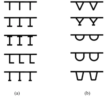
(24) Furthermore, a good orthotropic deck bridge can last more than 100 years, and needs less maintenance. Orthotropic decks are highly competitive when compared to other bridge types on life-cycle costs basis. Orthotropic decks are widely applied to replace old original concrete decks due to the light self weight. Meanwhile, there is no interruption during the replacement of bridge deck. One of the most famous examples is the Golden Gate Bridge as mentioned before. In recent years, there are many long span bridges redecked with orthotropic decks, such as Triborough Bridge and Whitestone Bridge. Although orthotropic deck bridges have many advantages, they have some drawbacks. One of the biggest barriers to using orthotropic decks is the willingness of bridge owners to believe the reputed longevity of orthotropic decks on the basis of current theory of fatigue even if recently tested in several experiments. The use of hot spot stress technique is yet foreign to the staffer of bridge authorities. High initial cost is the main cause of its rejection as a viable alternate.. 1.3 Orthotropic deck plate in bridge structure An orthotropic deck usually consists three main components, deck plate, floor beam (or crossbeam) and longitudinal rib (or stiffener), as shown in Figure 1-3 [5]. Fatigue failure is likely to occur at welded connections especially where rib runs across a floor beam (diaphragm). Here the details present complex geometries with significant stress concentrations. Design of orthotropic decks is primarily how the engineer manages to reduce stress when geometries are complex so as to reduce stress concentration below the endurance limit. Two types of longitudinal rib are used in orthotropic decks, as shown in Figure 1-4. The upper figure shows an “open” flat plate rib in a typical bridge framing. The lower figure shows a “closed” trapezoidal rib, which is inaccessible inside once welded to the deck plate.. 6.
(25) FIGURE 1-4 Typical components of orthotropic deck bridges (M. S. Troitsky, 1987).. Figure 1-5 illustrates several types of open-ribs (on the left) and closed ribs (on the right), which have been used in the evolution of this design technology. Both have an impact on the design of the “cutout” which will be discussed in Chapter 2.. (a). (b). FIGURE 1-5 Rib typologies: (a) open-ribs; (b) closed ribs. 7.
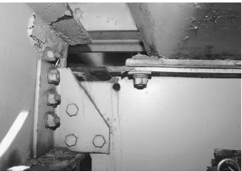
(26) 1.4 Optimization Technologies The evolution of the technology has shown that the design of an orthotropic deck is governed by fatigue and not by strength. Welded connections in orthotropic deck (see Figure 1-6) [6] are subject to fatigue cracking like in other steel structures. Cutout geometries play an important role in the severity of stress concentration. The development of computer science, Finite Element Method (FEM) plays a more and more important role in the improvement of these geometries so that fatigue effects can be minimized. With more powerful computer, bridge designer can develop better bridge models and compare geometric design in a short time.. FIGURE 1-6 Welded connections in orthotropic deck (T. Gurney, 2006).. For the purpose of increasing the longevity of orthotropic decks, fatigue enhancement techniques can be utilized in the welded connections. In general, fatigue enhancement methodologies can be categorized as follows: (1) those that introduce beneficial compressive stress; (2) those that reduce stress concentration; (3) those that remove defects in components; and (4) those that increase the rigidity in the connection, or that in some way reduce the stress concentration in hot spots. While these techniques have not been used in orthotropic decks, it is seen that they may contribute to lower fabrication costs by removal of the cut-out, while helping to keep deck weight low. 8.
(27) 1.5 Research Objectives The primary goal of this research is to develop an approach to improve the fatigue behaviors of orthotropic deck bridge through FEM and analytical techniques, by doing parametric studies of various geometric parameters. Furthermore, the fatigue enhancement technique, Fluid Bed Peening (FBP), is discussed based on a series of simple fatigue tests.. 1.5.1 Geometric optimization of orthotropic deck. The structure of orthotropic deck is very complex. The early analytical methods such as Pelikan-Esslinger method can’t assess the details where the concentrated stress existed, for instance, at the cutout and welded connections. It is well known that these details are very critical according to the studies conducted for the development of actual projects. The FEM technique is highly suitable to study stress concentrations of a multitude of designs in which single parameters are made to vary while others are held constant. This type of analysis will eventually evolve in an optimized design of a particular orthotropic deck. In past years, a large amount of experiments were carried out all over the world. Advanced Technology for Large Structural Systems (ATLSS) center at Lehigh University (U.S.A.) is continuing to investigate the fatigue performance of orthotropic deck through full-scale specimens and obtains fruitful results [7]. The redecking of the Williamsburg Bridge [8, 9], the Bronx Whitestone Bridge, and the Verrazzano Bridge were tested ATLSS center under the guide of Fisher. The prototypes to be tested were first developed by FE techniques. More and more FE software are applied to study the performances of orthotropic deck. Conner [10] studied the influence of traditional cutout to orthotropic deck via FEM. In the past few years, some important connections were studied by building fine meshed submodels. Figure 1-7 shows the FE model with cracks developed by Kornel Kiss [11]. 9.
(28) FIGURE 1-7 Submodel of rib-to-deck plate connection (Kornel Kiss, 2002).. In this research, FEM is applied to analyze the stress performance of orthotropic deck. Many Finite Element (FE) models would be developed in order to analyze the influences of cutout, bulkhead, and deck plate [12]. The applied loading is developed to obtain maximum stress range. Furthermore, submodels are developed based on the global analyses in order to obtain accurate stresses for calculating fatigue resistance, using the structural hot spot stress method. These analyses provide the loading background to fatigue life. The fatigue analysis is done by the use of structural hot spot stress approach in order to quantify stress ranges for which there is no “nominal stress” database (that which is available in design codes for stress away from the concentration). Based on this research, some suggestions are provided to bridge designers which can be helpful for improving the design of orthotropic decks.. 1.5.2 Fatigue enhancement. Another method for improving the longevity of orthotropic deck is to increase the fatigue resistance of the welded joint. The International Institute of Welding (IIW) provides quantitative values of how much one fatigue category can be improved for various enhancement procedures such as burr grinding, TIG dressing, peening, blasting, stress reliving, and others [13]. However, high accuracy in selection of operational parameters is demanded by traditional methods, such as shot peening [14]. 10.
(29) Otherwise, over shot peening can increase the defects of surface and cause initial cracks [15, 16]. FBP, a relatively new method, as a technique of surface treatments can dramatically improve the surface performance, and demands less operational parameters. Material tests done by M. Barletta et al. [17, 18] showed that FBP can optimize the roughness of material surface significantly. Figure 1-8 shows the optimized effect of surface roughness treated by FBP [18]. Furthermore, it is easy to control because less operational parameters are demanded. Thereby, fatigue tests are carried out in the laboratory to study the effect of treatment of FBP in this research. Fatigue enhancement techniques not only can be used to postpone the initiation of fatigue cracking, but also sometime can remedy small fatigue cracks [19]. This will be discussed detailed in Chapter 5. As a result, an approach for optimizing and enhancing the fatigue behaviors of orthotropic decks is provided in this research.. FIGURE 1-8 Surface roughness after treated 30 min:(a) 110o; (b) 130o; (c) 150o; (d) 170o; (e) 200o; (f) 230o (M. Barletta et al., 2007).. 11.
(30) References [1] Tvergaard V, Needleman A. Buckling of eccentrically stiffened elastic-plastic panels on two simple supports or multiply supported, Int. J. Solids Structures, 1975, Vol. 11: 647-663. [2] Troitsky MS. Stiffened Plates, Bending, Stability and Vibrations, Elsevier, 1976, New York. [3] Jen W. Strength of steel orthotropic deck with trapezoidal shaped longitudinal stiffeners. Lehigh University, 2006. [4] Yarnold MT, Wilson JL, Jen W, Yen BT. Local buckling analysis of trapezoidal rib orthotropic bridge deck systems. Bridge Structures, 2007; 3(2): 93-103. [5] Troitsky MS. Orthotropic Bridges - Theory and Design (2nd ed.). Cleveland, OH: James F. Lincoln Arc Welding Foundation, 1987. [6] Gurney T. Cumulative damage of welded joints. Woodhead Publishing Limited, 2006. [7] Fisher JW. Evolution of fatigue-resistant steel bridge. Distinguished Lectureship. Transportation Research Board, 76th Annual Meeting, Washington DC, January 12-16. Paper No. 971520.1-22, 1997. [8] Bocchieri WJ, Fisher JW. Williamsburg Bridge Replacement Orthotropic Deck As-built Fatigue Test. ATLSS Report No. 98-04. May, 1998. [9] Connor RJ, Fisher JW. Results of Field Measurements on the Williamsburg Bridge Orthotropic Deck. ATLSS Report No. 01-01. January, 2001. [10] Connor RJ. Influence of cutout geometry on stresses at welded rib to diaphragm connections in the steel orthotropic bridge decks. Journal of the Transportation Research Board, 2004; No.1892, 78-87. [11] Kiss K, Dunai L. Fracture mechanics based fatigue analysis of steel bridge decks by two-level cracked models. Computers and Structures, 2002; 80: 2321–2331. [12] Abruzzese D, Grimaldi A, Qian ZH. Fatigue Behaviors of Cutout at Crossbeam of Trapezoidal Rib Orthotropic Deck; International Orthotropic Bridge Conference, U.S.A., 2008: 256-266. [13] Haagensen P.J, Maddox S J. IIW recommendations post weld improvement steel and 12.
(31) aluminium structures. IIW Commission XIII-1815-00. International Institute of Welding, 2002. [14] Guagliano M, Vergani L. An approach for prediction of fatigue strength of shot peened components, Engineering Fracture Mechanics, 2004; Vol. 71: 501-512 [15] Mutoh Y, Fair GH, Noble B, Waterhouse RB. The effect of residual stresses induced by shot-peening on fatigue crack propagation in two high strength aluminum alloys. Fatigue Fract Eng Mater Struct, 1987; Vol. 10(4): 216–72. [16] Tekeli S. Enhancement of fatigue strength of SAE 9245 steel by shot peening. Mater Lett., 2002; Vol. 57: 604–608. [17] Barletta M, Lambiase F, Tagliaferri V. Improvement of fatigue behaviour high strength aluminium alloys by Fluid Bed Peening (FBP). Key Engineering Materials, 2007; Vol.344: 87-95. [18] Barletta M, Bolelli G, Guarino S, Lusvarghi L. Development of matte finishes in electrostatic (EFB) and conventional hot dipping (CHDFB) fluidized bed coating process. Progress in Organic Coatings, 2007; Vol. 59: 53–67. [19] Qian ZH, Abruzzese D. Fatigue Failure of Welded Connections at Orthotropic Bridges. Frattura ed Integrità Strutturale. Gruppo Italiano Frattura, 2009; 9: 105-112.. 13.
(32) 14.
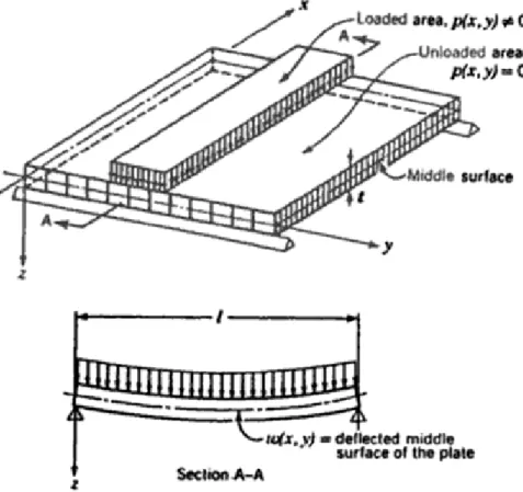
(33) CHAPTER 2 STRUCTURAL ANALYSIS OF ORTHOTROPIC DECK An orthotropic plate is defined as a plate having elastic properties in orthogonal direction, as shown in Figure 2-1 [1]. A large amount of investigations had been carried out on orthotropic steel deck systems in the last century, including elastic analysis of stiffened plates, buckling analysis of deck plate components, and strength evaluation of orthotropic deck and components. The development of theory optimizes the design and the manufacture to the orthotropic deck plate. Moreover, the appearance of FE software brings a great break through for analyzing the complex details in orthotropic decks.. 2.1 Classical Theories Orthotropic deck not only acts as deck plate, but also part of main girder. It is the upper flange for floor beam and longitudinal beam, as well as for main girder. Orthotropic deck is often studied by dividing into three different structural systems: (1) Main girder system; Deck plate and longitudinal ribs act as the upper flange of main girder. (2) Deck system; It is composed by deck plate, floor beams and longitudinal ribs. Deck plate acts as the common upper flange of floor beams and longitudinal ribs. The system is supported by the main girders, and only undertakes vehicle loading. The real bearing capacity of this structure is much higher than the results calculated by small deflection elastic theory due to the high plastic reserved capacity. (3) Deck plate system; It includes only deck plate which acts as homogeneous and continuous plate supported by longitudinal ribs and floor beams. Vehicle loading affects directly on the system, and delivers to longitudinal ribs and floor beams. Although the deck plate has constant thickness and same material, the different elastic modulus and different Poisson ratios bring the different properties in the orthogonal 15.
(34) directions. Thus, the deck plate is called orthotropic deck.. FIGURE 2-1 Basic designation of orthotropic deck plate as an anisotropic system (Xanthakos, 1994).. 2.1.1 Introduction of orthotropic plate theories. Gehiring and Boussinesq introduced firstly the analysis of an isotropic plate, and Huber presented the complete solution for isotropic plate. The famous Huber’s equation is presented as Equation (2.1) which providing the relationship between the lateral deflection and the loading of an orthotropic deck. ∂4w ∂4w ∂4w D x 4 + 2 H 4 4 + D y 4 = p ( x, y ) ∂x ∂x ∂y ∂y. (2.1). Where, w is the lateral deflection of the middle surface of the plate at point ( x, y ) as shown in Figure 2-1; Dx , D y and H are rigidity coefficients, and p( x, y ) is the load density at any point expressed as a function of the coordinate x and y . 16.
(35) The basic hypothesis proposed by Huber to calculate the overall bending deflections and bending stresses in a stiffened plate, is to replace it by an equivalent orthotropic plate of constant thickness having the same orthogonal stiffness characteristics. It is called the Method of Elastic Equivalence (MEE). Guyon [2] utilized the method to analyze a deck without torsional stiffness of the longitudinal rib. Massonnet [3] extended Guyon’s method to include the torsional stiffness. Morice, Little and Rowe [4] applied the previous theory to concrete bridges. The design technique is concluded by Rowe [5] which is based on a set solution of the governing partial differential equation at a stage before the widespread availability of computers. The governing differential equations for large deflection orthotropic plate theory are the equilibrium equation and the compatibility equation. Considering the idealized initial imperfection, boundary conditions and load application, Paik and Thayamballi [6] solved the governing differential equations. Cornelus [7] treated the orthotropic deck as equivalent to a continuum without considering the spacing between floor beams. For the purpose of design, various methods have been developed: (1) The Pelikan-Esslinger method [8], based on Huber’s equation, is simplified but sufficient accurate. It assumes that the deck system is a continuous orthotropic plate, rigidly supported by longitudinal main girders and elastically supported by the floor beams. The parameters expressing certain rigidities of the orthotropic deck are disregarded in the method, as the parameters are considered of little importance during the design. The method does not provide the information on the load carrying strength of the deck panel and the stress status of details, for example, the stress near the cutout. (2) The equivalent gird method is assumed to perform as an integral unit. It assumes that the deck plated slit between the longitudinal ribs, which are treated as individual beams between panel points of the grid system, with the deck plate strips acting as the upper flanges. The effect of the deck plate rigidity perpendicular to the ribs is disregarded and should be considered separately. (3) The equivalent orthotropic plate method (orthotropic slab method) in the AISC 17.
(36) manual [9] and James F. Lincoln Electric manual [10], assumes that the rigidities of both the floor beams and the longitudinal ribs are uniformly distributed throughout the deck in the direction perpendicular to the respective member. Therefore, the actual discontinuous structure of the steel plate deck is represented as an idealized substitute orthotropic slab. (4) The thin-walled-beam method, as an elastic analysis method, accounts for the torsional distortion effects of box girders with an orthotropic deck [11]. It is also referred as the folded plate theory [12]. Furthermore, the design of orthotropic deck can be solved by Finite Difference and Finite Element techniques.. 2.1.2 Orthotropic Plate Theory. Timoshenko [13] elaborated thoroughly the orthotropic plate theory in 1959, and Figure 2-2 shows the stress state of an orthotropic deck. Timoshenko assumed that the material of the plate has three planes of symmetry with respect to its elastic properties. Taking these planes as the coordinate planes, the relations between the stress and strain components for the case of plane stress in the xy plane can be represented by the following equations:. σ x = E x' ε x + E ''ε y σ y = E y' ε y + E ''ε x. (2.2). τ xy = Gγ xy where, E x' , E y' and E '' are elastic modulus, and G is shear modulus. Considering the bending of a plate made of such a material, it is assumed as before that linear elements perpendicular to the middle plane ( xy plane) of the plate before bending remain straight and normal to the deflection surface of the plate after bending. Hence, the following expressions can be used for the components of strain:. ε x = −z. ∂2w ∂2w ε = − z y ∂x 2 ∂y 2 18. γ xy = −2 z. ∂2w ∂x∂y.
(37) The corresponding stress components, from Equations. (2.2), are. ⎛. σ x = − z⎜⎜ E x'. 2 ∂2w '' ∂ w ⎞ ⎟ + E ∂y 2 ⎟⎠ ∂x 2. ⎝ ⎛ ∂2w ∂2w ⎞ σ y = − z ⎜⎜ E y' 2 + E '' 2 ⎟⎟ ∂y ∂x ⎠ ⎝ ∂2w τ xy = −2Gz ∂x∂y. (2.3). FIGURE 2-2 Forces of orthotropic plate (Timoshenko, 1959).. With these expressions for stress components, the bending and twisting moments are ⎛ ∂2w ∂2w ⎞ M x = −⎜⎜ Dx 2 + D1 2 ⎟⎟ ∂x ∂y ⎠ ⎝ ⎛ ∂2w ∂2w ⎞ ⎜ M y = −⎜ D y 2 + D1 2 ⎟⎟ ∂y ∂x ⎠ ⎝ ∂2w M xy = −2 Dxy ∂x∂y. (2.4). in which E ' h3 Dx = x 12. Dy =. E y' h 3 12. D1 =. E '' h 3 12. Dxy =. Gh 3 12. (a). It is obtained the following equation for anisotropic plates: Dx. ∂4w ∂4w ∂4w + H + D 2 = q ( x, y ) y ∂x 4 ∂x 4 ∂y 4 ∂y 4. in which 19. (2.5).
(38) H = D1 + 2 Dxy. 2.1.2.1 Determination of rigidities in various specific cases. The expressions (a) given for the rigidities need minor modifications according to the natural material utilized. Common values of the rigidities in some practical cases are presented in the following. a) Reinforced concrete slabs Let be E s Young’s modulus of steel, E c that of the concrete, ν c Poisson’s ratio for concrete, and n = Es / Ec . In terms of the elastic constants we have approximately. ν c = E '' / Ex' E y' . For a slab with two-way reinforcement in the directions x and y , it is assumed that: Dx =. Ec [ I cx + (n − 1) I nx ] 1 − ν c2. Dy =. Ec [ I cy + (n − 1) I ny ] 1 − ν c2. (2.6). D1 = ν c D x D y D xy =. 1 −ν 2 2. Dx D y. With the expression given for D xy it is obtained: H = Dx D y. b) Plywood For a plate glued together of three or five plies, the constants which can be used are given in Table 2-1.. 20.
(39) TABLE 2-1 Elastic Constants for Plywood (unit=106psi). Material. E x'. E y'. E ''. G. Maple, 5-ply. 1.87. 0.60. 0.073. 0.159. Afara,3-ply. 1.96. 0.165. 0.043. 0.11. Gaboon, 3- ply. 1.28. 0.11. 0.014. 0.085. Brich, 3- and 5-ply. 2.00. 0.167. 0.077. 0.17. Brich with bakelite membranes. 1.70. 0.85. 0.061. 0.10. c) Corrugated sheet Figure 2-3 shows the form of the corrugation, and the thickness is obtained that z = f ⋅ sin. πx l. FIGURE 2-3 The form of the corrugation (Timoshenko, 1959).. It is assumed that s is the length of the arc of one-half a wave, then. 21.
(40) l Eh 3 Dx = s 12(1 − ν c2 ) D y = EI. (2.7). D1 ≈ 0 H = 2 D xy =. s Eh 3 l 12(1 + ν ). d) Plate reinforced by equidistant stiffeners in one direction For a plate reinforced symmetrically with respect to its middle plane, as shown in Figure 2-4, it is taken: Dx = H =. Eh 3 12 1 −ν 2. (. ). 3. Eh E 'I Dy = + a1 12 1 −ν 2. (. (2.8). ). FIGURE 2-4 Plate reinforced by equidistant stiffeners in one direction (Timoshenko, 1959).. in which E and v are the elastic constants of the plate, E ' the Young modulus, and I the moment of inertia of a stiffener, taken with respect to the middle axis of the cross section of the plate. e) Plate cross-stiffened by two sets of equidistant stiffeners 22.
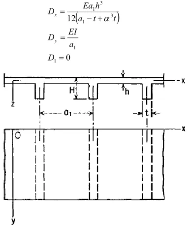
(41) Provided the reinforcement is still symmetrical about the plate, then. E ' I1 Eh 3 Dx = + b1 12 1 −ν 2. (. Dy = H=. ). E'I2 Eh 3 + a1 12 1 −ν 2. (. ). Eh 3 12 1 −ν 2. (. (2.9). ). where, I 1 is the moment of inertia of one stiffener, and b1 is the spacing of the stiffeners in direction x , and I 2 and a1 are the respective values for the stiffening in direction y . f) Slab reinforced by a set of equidistant ribs In the case, as shown in Figure 2-5, the theory established can give only a rough idea of the actual state of stress and strain of the slab. Suppose E be the modulus of the material (for instance, concrete), I the moment of inertia of a T section of width a1 and α = h / H . Then it is assumed that. Dx =. Ea1h 3 12 a1 − t + α 3t. Dy =. EI a1. (. ) (2.10). D1 = 0. FIGURE 2-5 Slab reinforced by a set of equidistant ribs (Timoshenko, 1959). 23.
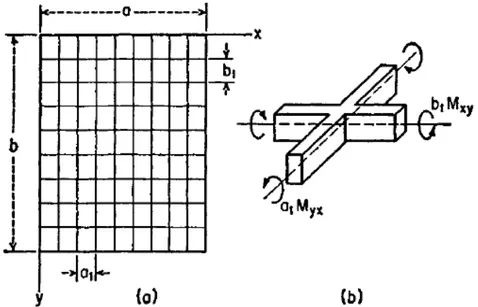
(42) The effect of the transverse contraction is neglected in the foregoing formulas. The torsional rigidity, finally, may be calculated by means of the expression Dxy = Dxy' +. C 2a1. where, Dxy' is the torsional rigidity of the slab without the ribs and C the torsional rigidity of one rib.. 2.1.2.2 Application of the theory to the calculation of gridworks. Equation (2.5) can be applied to the grid system as well, as shown in Figure 2-6.. FIGURE 2-6 Application of the theory to the calculation of grid-works (Timoshenko, 1959).. This consists of two systems of parallel beams spaced equal distances apart in the x and y directions and rigidly connected at their points of intersection. The beams are supported at the ends, and the load is applied normal to the xy plane. If the distances a1 and b1 between the beams are small in comparison with the dimensions a and b of the grid, and if the flexural rigidity of each beam parallel to the x axis is equal 24.
(43) to B1 and that of each beam parallel to y axis is equal to B2 , then they can be substituted in Equation (2.5) Dx =. B1 b1. Dy =. B2 b2. The quantity D1 in this case is zero, while the quantity Dxy can be expressed in terms of the torsional rigidities C1 and C 2 of the beams parallel to the x and y axes, respectively. Therefore, it is considered the twist of an element as shown in Figure 2-6 and we obtain the following relations between the twisting moments and the twist ∂ 2 w / ∂x∂y : M xy. C1 ∂ 2 w = b1 ∂x∂y. M yx. C1 ∂ 2 w =− a1 ∂x∂y. (2.11). Substituting these expressions in the equation of equilibrium, it is found that in the case of the system represented in Figure 2-6a the differential equation of the deflection surface is B1 ∂ 4 w ⎛ C1 C 2 ⎞ ∂ 4 w B2 ∂ 4 w ⎟ ⎜ + =q + + b1 ∂x 4 ⎜⎝ b1 a1 ⎟⎠ ∂x 2 ∂y 2 a1 ∂y 4. (2.12). which is of the same form as Equation (2.5). In order to obtain the final expressions for the flexural and torsional moments of a rib, the moments should be multiplied, such as given by Equations (2.4) and valid for the unit width of the grid, by the spacing of the ribs. The variation of the moments, for example M x and M xy , may be assumed parabolic between the points (m − 1) and. (m + 1). and the shaded area of the diagram (as shown in Figure 2-7) may be assigned. to the rib (m ) running in the direction x . Then, observing the expressions (2.4), it is obtained the following approximate formulas for both moments of the rib (m ) :. 25.
(44) ⎛ ∂2w ⎞ ⎛ ∂2w ⎞ ⎤ B1 ⎡⎛ ∂ 2 w ⎞ M x = − ⎢⎜⎜ 2 ⎟⎟ + 22⎜⎜ 2 ⎟⎟ + ⎜⎜ 2 ⎟⎟ ⎥ 24 ⎣⎢⎝ ∂x ⎠ m−1 ⎝ ∂x ⎠ m ⎝ ∂x ⎠ m+1 ⎦⎥ M xy. ⎛ ∂2w ⎞ ⎛ ∂2w ⎞ ⎤ C ⎡⎛ ∂ 2 w ⎞ ⎟⎟ + 22⎜⎜ ⎟⎟ + ⎜⎜ ⎟⎟ ⎥ = 1 ⎢⎜⎜ 24 ⎢⎣⎝ ∂x∂y ⎠ m−1 ⎝ ∂x∂y ⎠ m ⎝ ∂x∂y ⎠ m+1 ⎥⎦. (2.14). FIGURE 2-7 Diagram of moment between (m − 1) and (m + 1) (Timoshenko, 1959). For ribs of the direction y, it needs to interchange x and y in the foregoing expressions and replace B1 by B2. and C1. by C 2 ; (m − 1) , (m ) , and (m + 1). then denote three successive joints on a rib having the direction x . Two parameters largely defining the elastic properties of a grid and often used in calculation are. λ=4. The parameter λ. B2b1 B1a1. C1 C y + 1 b1 a1 μ= 2 B1 B2 a1b1. multiplied by the side ratio a / b. (Figure 2-7) yields the. relative carrying capacity of a rectangular plate in the directions x and y , whereas the parameter μ. characterizes the torsional rigidity of a grid as compared with its. flexural rigidity. Equation (2.12) has been extensively used in investigating the distribution of an arbitrarily located single load between the main girders of a bridge stiffened in the transverse direction by continuous floor beams. 26.
(45) 2.1.3 The Pelikan-Esslinger Method. The Pelikan-Esslinger method [8] was proposed by Germany researchers W. Pelikan and M. Esslinger in 1950s, then it was widely used and adopted as well by “Design manual for orthotropic steel plate deck bridges” (1963) [9]. The detailed analysis of the orthotropic deck is well documented in the design manual [9]. This method is also based on the application of Huber's equation. Some assumptions are presented prior to apply P-E method to calculate the deflections and stresses of orthotropic deck: a) the distance between the ribs should be very small compared to the length of plate edge, that means stiffeners should be put closely; b) the distribution of the ribs (both longitudinal or transverse) should be uniform; c) the plate stiffness keeps the same while the loading and boundary conditions change; d) the material of the ribs and the plate should be the same; e) the connections of the rib and the plate should be tight and deep-set. The design procedure is divided into two stages (as shown in Figure 2-8). In the first stage, it is assumed that floor beams and the main girders are infinitely rigid. The deck plate is supported by the floor beams, as shown in Figure 2-8a. The moments of longitudinal ribs and transversal floor beams are calculated in this stage. In the second stage, the moments calculated in the first step is modified according to the results of the floor beams considering the elastic deformation, see Figure 2-8b. It is in good agreement to the practical situation, shown in Figure 2-8c. The longitudinal flexural rigidity D y is much larger than the transversal flexural rigidity D x , therefore, it is assumed that D x ≈ 0 ; The torsional rigidity H of open rib orthotropic deck is also very small, thus, it is assumed that H ≈ 0 . According to the above, it is obtained that a) open rib orthotropic deck: D x = 0 , H = 0 ; 27.
(46) b) closed rib orthotropic deck: D x = 0 .. 2.1.3.1 Open rib orthotropic deck. a) Solutions of continuous beam supported rigidly For an open rib orthotropic deck, it is assumed that D x = 0 , H = 0 , then Dy. ∂4w = q ( x, y ) ∂y 4. (2.15). Figure 2-9 shows the influence lines of internal forces at the continuous beam supported rigidly.. 28.
(47) (a) The first step.. (b) The second step. FIGURE 2-8 Flowchart of the Pelikan-Esslinger method. 29.
(48) FIGURE 2-9 The influence lines of continuous beam.. 1) Moment in the middle of the longitudinal ribs M m When the concentrated loading P acts between the area 0-0, the moment of the center point can be calculated by. ⎛ Mm ⎞ y y ⎜⎜ ⎟⎟ = 0.1830⎛⎜ ⎞⎟ + 0.3170⎛⎜ ⎞⎟ ⎝t⎠ ⎝t⎠ ⎝ Pt ⎠ 0−0. 2. (2.16). The maximal value of the influence line M m occurs at y / t = 0.5 : ⎛ Mm ⎜⎜ ⎝ Pt. 2 ⎡ ⎞ y⎞ y⎞ ⎤ ⎛ ⎛ ⎟⎟ = ⎢0.1830⎜ ⎟ + 0.3170⎜ ⎟ ⎥ = 0.1708 ⎝t⎠ ⎝ t ⎠ ⎦⎥ y =0.5 ⎠ max ⎢⎣. (2.17). t. For the other situations:. ⎛ Mm ⎜⎜ ⎝ Pt. 2 3 ⎡ ⎞ y⎞ y⎞ y⎞ ⎤ ⎛ ⎛ ⎛ m ⎟⎟ = (− 0.2679) ⎢− 0.1830⎜ ⎟ + 0.3170⎜ ⎟ − 0.1340⎜ ⎟ ⎥ ⎝ t ⎠ ⎥⎦ ⎝t⎠ ⎝t⎠ ⎢⎣ ⎠ m−( m+1). 30. (2.18).
(49) 2) Moment M s at the supporting point of longitudinal rib The moment can be calculated by ⎛ Ms ⎜⎜ ⎝ Pt. 2 3 ⎡ ⎞ y⎞ y⎞ y⎞ ⎤ ⎛ ⎛ ⎛ m ⎟⎟ = (− 0.2679) ⎢− 0.5⎜ ⎟ + 0.866⎜ ⎟ − 0.366⎜ ⎟ ⎥ ⎝t⎠ ⎝t⎠ ⎝ t ⎠ ⎦⎥ ⎠ m−(m+1) ⎣⎢. (2.19). Maximal M s occurs at d / t = 0.3804 , then ⎛ Ms ⎜⎜ ⎝ Pt. ⎞ c ⎟⎟ = −0.085 + 0.1494⎛⎜ ⎞⎟ ⎝t⎠ ⎠ max. 2. (2.20). 3) Reaction at the node Ro Through the calculation based on the influence lines, it is obtained that: for Span “0-1” 2 3 ⎡ ⎛ Ro ⎞ ⎛ y⎞ ⎛ y⎞ ⎤ ⎜ ⎟ = ⎢1 − 2.19⎜ ⎟ + 1.1962⎜ ⎟ ⎥ ⎝t⎠ ⎝ t ⎠ ⎥⎦ ⎝ P ⎠ 0−1 ⎢⎣. (2.21). for Span “m-(m+1)” 2 3 ⎡ ⎛ Ro ⎞ ⎛ y⎞ ⎛ y⎞ ⎛ y⎞ ⎤ m −1 = (− 0.2679) ⎢− 8038⎜ ⎟ + 1.3923⎜ ⎟ − 0.5885⎜ ⎟ ⎥ ⎜ ⎟ ⎝t⎠ ⎝t⎠ ⎝ t ⎠ ⎦⎥ ⎝ P ⎠ m −( m+1) ⎣⎢. (2.22). b) Modify according to the deflection of floor beam It is assumed that the floor beams are rigid in the first stage, therefore the moments in the rib should be modified. The additional moment of floor beam in direction x can be calculated by. ΔM t = Q0 ta. Q1x Qo. K m η im t m =0 p ∞. ∑. (2.23). While the decreased moment of transverse stiffener in direction x can be calculated by 2. ∞ ⎤ K ⎛ b ⎞ Q ⎡K ΔM q = Q0 ⎜ ⎟ 1x ⎢ 0 − ∑ m ϑ 0 m ⎥ ⎝ π ⎠ Qo ⎣ P m=0 p ⎦. 31. (2.24).
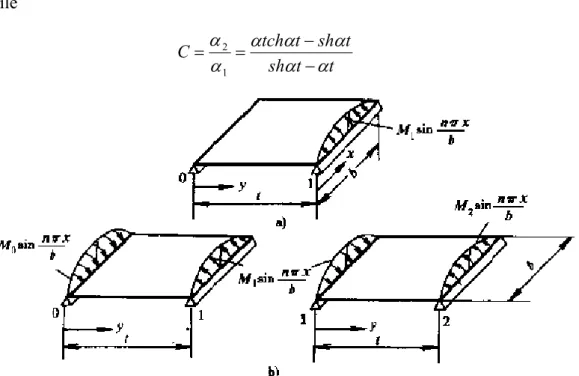
(50) 2.1.3.2 Closed rib orthotropic deck. For open rib orthotropic deck, it is assumed that Dx = 0 , H = 0 , then 2H. ∂4w ∂4w + D = q ( x, y ) y ∂x 4 ∂y 4 ∂y 4. (2.25). The solution is 2H. ∂4w ∂4w + =0 D y ∂x 4 ∂y 4 ∂y 4. nπx w = ∑ (C1 shay + C 2 chay + C3αy + C 4 )sin b n =1 ∞. (2.26). in which. α=. 2 H nπ Dy b. a) Three-moment equation of continuous plate Figure 2-10 shows a simple supported plate with different loads. Through the calculation, it is assumed that M 0α 1 + 2 M 1α 2 + M 2α 1 = 0 while C=. α 2 αtchαt − shαt = α1 shαt − αt. FIGURE 2-10 Single plate for calculating transverse coefficient K . 32. (2.27).
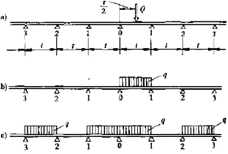
(51) then M 0 + 2CM 1 + M 2 = 0 Due to the moment decreases with the extending of span, then M 1 = kM 0 , M 2 = k1 M 1 = k 2 M 0 ,… Therefore,. (. ). M 0 1 + 2Ck + k 2 = 0 k = −C + C 2 − 1. (2.28). b) The moments of supported surfaces Different loads on the plate are shown in Figure 2-11.. FIGURE 2-11 Different loading conditions on supported lines.. For load case a: ⎡ ⎤ ⎢ ⎥ 1 k M 00−1 = Qt * ⎢1 − αt ⎥ 2α (1 − k ) ⎢ ch ⎥ 2⎦ ⎣ 0− 2 0 −1 M 0 = kM 0 For load case b:. 33. (2.29).
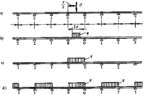
(52) M. 0 −1 0. M. 1− 2 0. qt 2 k ⎡ αt αt ⎤ 1 − th ⎥ = * 2 2α (1 − k ) ⎢⎣ 2 2⎦ = kM. (2.30). 0 −1 0. While the loads act the full line: M 0 = 2M 00−1 (1 + k 2 + k 3 + ...) =. 2 M 00−1 1− k. M 0 = 2M 00−1 (1 + k 2 + k 4 + ...) =. 2M 00−1 1− k 2. For load case c: (2.31). c) The moment in the middle of the supports Figure 2-12 shows the different loads between two nodes in the plate.. FIGURE 2-12 Different loading conditions in the middle of plate.. For load case a:. M m0−0. ⎡ ⎛ ⎢ 1 αt M 0* ⎜⎜ 1 th + 1− = Qt ⎢ αt t ⎜ ⎢ 2αt 2 ⎜ ch 2 ⎝ ⎣⎢ 34. ⎞⎤ ⎟⎥ ⎟⎥ ⎟⎥ ⎟ ⎠⎦⎥. (2.32).
(53) For load case b:. M m0−0. ⎧ ⎡ ⎛t ⎞ ⎛ chα ⎜ − e ⎟ ⎪ ⎢ M 0* ⎜ shαe 1 2 ⎪ 1 ⎢ ⎝ ⎠ ⎜1 − = Qt ⎨ 2 1 − + t α t αe ch αt te 2 α ⎜ ⎢ ⎪ ch ⎜ ⎢ 2 2 ⎝ ⎪⎩ ⎣. ⎞⎤ ⎫ ⎟⎥ ⎪ ⎟⎥ ⎪⎬ ⎟⎥ ⎪ ⎟⎥ ⎠⎦ ⎪⎭. (2.33). For load case c: M m0−0. αt ⎡ ⎤ ch − 1 * ⎢ M α t 2 ⎛ ⎞⎥ 2 = qt ⎢1 − + 0 ⎜1 − ch ⎟⎥ t ⎝ αt 2 ⎠⎥ ⎢ (αt )2 ch αt 2 ⎣ ⎦. For load case d:. M = M m0−0 + 2(1 + k 3 + k 5 + ...) = M m0−0 +. 2k M 00−1 1− k 2. (2.34). d) The moment of closed rib Similar to the open rib deck, the moment of closed rib deck can be calculated by ∞. M y = ∑ Qn sin n =1. ∞ Q η nπx η n = Q0 t ∑ nx n b n =1 Q0 t. (2.35). where, η n is the longitudinal distance of the influence area of the deck plate. The actual moment M R of the deck rib can be calculated based on the result of the center moment of the longitudinal rib, as shown in Figure 2-13: M R = (a + e )M y. FIGURE 2-13 Moment of the closed rib. 35. (2.36).
(54) 2.1.3.3 The Pelikan-Esslinger method in AISC. As expressed in the 1963 AISC Design Manual for Orthotropic Steel Plate Deck Bridges [9], the simplifications attributed to Esslinger and Pelikan are as follows: a) Open ribs 1) The deck plate is treated as a beam - i.e. the plate is given rigidity in the short direction from rib to rib. Deflection and flexure (at 25.9 ksi/178.6MPa) and shear criteria governed, giving a 3/8 inc h (0.95cm) thickness over a 12 inch (30.48cm) rib spacing, for a 12 kip (53.4kN) wheel load. 2) The wheel load is distributed to adjacent ribs as in a beam on elastic foundations. 3) Effective width of deck plate (used to calculate the rib/deck plate composite properties over major rib carrying load) is a function of its share of the wheel load and of the “effective” rib span. It is usually larger than the actual rib spacing. The effective rib span is always 0.7 times the actual span. 4) Ribs “near” the floor beam support are treated as resting on rigid foundations; ribs “near” floor beam mid span are treated as resting on flexible foundations. Ribs near mid span will have larger positive moments and smaller negative moments than those near floor beam support. The AISC manual gives Moment Relief formulae all based on sinusoidal deflection of the floor beam. In short, concepts of orthotropy are abandoned in favor of partial compatibility between beams. Global transverse rigidity is ignored; influence lines for beams are invoked. b) Closed ribs 1) The torsional rigidity of the deck plate is governed by G, K and μ as defined by the following equation: H=. 1 ⎛ μGK ⎞ ⎜ ⎟ 2⎝ a+e ⎠ 36. (2.37).
(55) Where G is the shear modulus for steel, K is a factor representing the physical properties and geometries of the rib such: K=. 4 A2 (u / t r ) + (a / t p ). (2.38). Where. A. is the area enclosed by the closed rib;. u. is the entire length of the closed rib plate;. a. is the rib width where it is joined to the deck plate;. tr. is the thickness of the rib plate;. tp is the thickness of the deck plate; e. is the spacing between ribs stems of adjacent ribs – i.e. a + e = rib. spacing;. μ is a number less than 1 which accounts for the reduction of the torsional rigidity due to the flexibility of the deck plate. The AISC manual provides lengthy formulae for evaluating this factor for four closed rib geometries, and. H is the distributed rigidity per unit width of deck. 2) The transverse rigidity of the deck plate and the ribs are ignored. 3) Esslinger/Pelikan solved the Huber differential equation and provided charts for longitudinal moments for various loads and spans. 4) Adjustments are made to moments based on floor beam rigidity in the same way as is done for open ribs. Torsional moments at the deck floor beam support were not sought. Also, the introduction of a stiffening intermediate diaphragm that is not supported on the girders, but merely spreads the load to more ribs represents a complication that was not dealt with by Pelikan and Esslinger. 37.
(56) What Should be Noted. The effective width of a discrete stiffened plate is smaller than that of a fully continuous orthotropic plate. It should be recognized that only the deck plate is continuous. Trough shaped stiffeners are not fully effective in torsion because of cross-section distortion. Guidance is available on suitable methods of accommodating the reduction in rigidity. In principle, the design of the deck should be verified separately for static strength and fatigue resistance. For static strength, the individual components of the deck need to be checked for the following stresses, in combination: a) Longitudinal stresses from participation in overall bending of the superstructure; b) Transverse stresses from participation in bending of the cross girder; c) Longitudinal stresses and shear stresses from bending of the stiffened plate between cross girders; d) Transverse bending of the deck plate between trough webs. In practice, adequacy is demonstrated by experience rather than by calculation of the very complex elastic stress fields. The flanges of bridge cross-sections are usually relatively wide with respect to their spans. The effects of shear lag need, therefore, to be included in the bending analysis. Shear lag effects cause the stress distribution over the cross-section to be non-linear. The maximum stress values occur at the flange-to-web junctions. The effective width is defined by the condition that the stresses at the flange-to-web junction, according to engineering bending theory, must be identical to the maximum stresses calculated by applying the mathematical theory of elasticity.. 2.2 Finite Element Methods Although traditional classic theories are very important to the design of orthotropic deck bridge, the assumptions and simplifications make the solutions existing errors, 38.
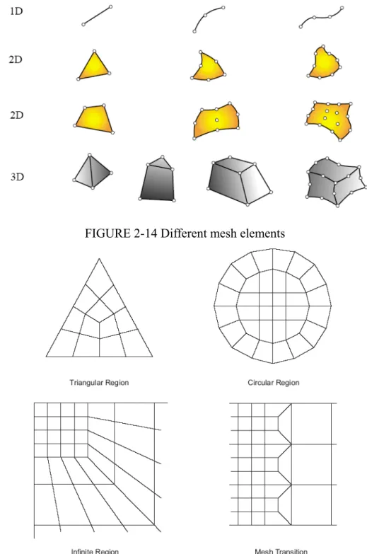
(57) especially at details. For example, the Pelikan-Esslinger method can be used to calculate accurately the stresses of longitudinal ribs, while it can not calculate the stresses around the cutout in the diaphragm. The Pelikan-Esslinger method can be applied to the preliminary design or the checking of FEM analysis. More precise method is necessary for calculating the stresses of critical connections, especially near the positions where support vehicle loads. With the development of the science and technology, more and more numerical analysis methods can be used to calculate the stress state in the orthotropic deck. Finite Strip method was presented by Cheng. Y. K [14] in 1969. It was developed by Powell and Ogden [15] through a large number of investigations, and now is called Finite Element Method (FEM). There are many software can be used to carry out the analysis of orthotropic deck, such as SAP2000, LUSAS, ABQUAS and ANSYS. More complicated problems can be solved, and more accurate results can be obtained taking account into the more advanced computer.. 2.2.1 Advantages of FEM. FE analysis calculating by powerful computer is one of the most effective methods in numerical analysis. FEM provides a large number of advantages, such as fast modeling, accurate analyzed results and economic compared to laboratory tests. Fast modeling. The Modeling of a structure provided by FE software costs much less. time than the test in laboratory. A structural model developed by FEM often takes a few weeks or even several days while takes several moths in laboratory. Once the model is built, it is easy to modify in FE software through changing the parameters, thus, plenty of time is saved. For example, different load cases to an orthotropic deck can be applied to the same model and can be computed even in one running. Accurate analyzed results. Almost any kind of details can be simulated in FE. software through different models. Both elastic analysis and plastic analysis can be carried out by FE analysis. A great number of different meshed elements are provided 39.
(58) in FE software, from one-dimension to three-dimension, as shown in Figure 2-14. Each kind of element has several different meshes, and it can make the model more close to the real project. Figure 2-15 shows different meshes in two-dimension structures. Given good meshes to an orthotropic deck, better analyzed results can be obtained for the critical connections.. FIGURE 2-14 Different mesh elements. FIGURE 2-15 Different meshes of 2D structures 40.
(59) Economy. Laboratory test of an orthotropic deck is always very expensive, especially. for prototype test. It needs a large number of machines, materials, and labor forces, therefore, it costs too much. However, numerical analysis via FE software is very economic compared with the laboratory test. A powerful computer is not too expensive to afford for a research group or a design office today, it usually costs about 2000 euro to 4000 euro. Costs related with software range from several thousands euro per year to several ten thousands euro per year. Many cases can be analyzed in one year through a powerful computer and software, thus, a mass of money can be saved.. 2.2.2 Disadvantages of FEM. Although FEM provides many advantages in analyzing orthotropic decks, there are several disadvantages should be noted to the bridge designers. Reasonable assumptions should be provided to develop an orthotropic deck model, such as boundary conditions and load cases. Improper assumptions would cause the analyzed results deviating from the real situation. In addition, different meshes provide different results, and sometimes may be very obvious, thus, the designers or users must be very familiar with the software. Considerable time and effort must be paid to build a detailed model with fine meshes, especially for a 3D model. A good designer not only must be competent in the use of FE software, but also has a thorough comprehension to orthotropic decks.. 2.2.3 Application of FEM in orthotropic deck. Both laboratory test and FEA are important to the study of the stress behaviors in an orthotropic deck structure. FEA is preferred by bridge designers because it is a fast and efficient way to calculate the stresses in an orthotropic deck. Also, FEM is a way provided to verify the results of laboratory tests. 41.
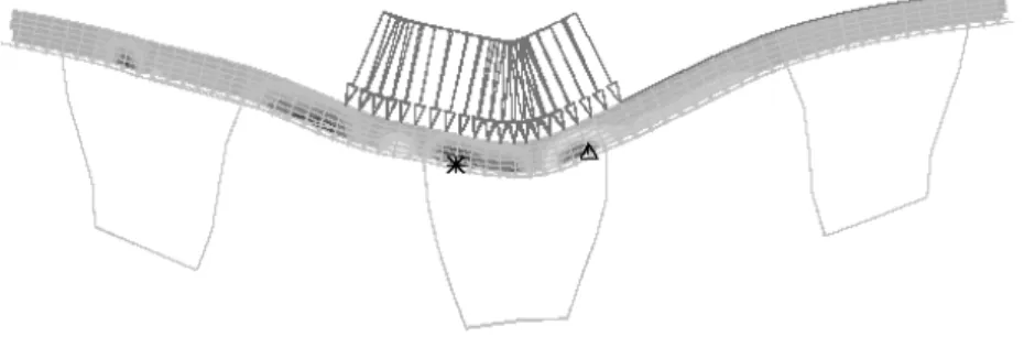
(60) Tinawi [16] calculated the deflections and stresses of the deck plate by FEM. Although the results were not very precise, they were strongly useful for bridge designers. Figure 2-16 shows the deflections obtained from FEA and compared with the results of the laboratory tests. With the development of computer science and FE software, more and more investigations, especially for the fatigue evaluation of orthotropic deck, are carried out recently by researchers via FEA.. FIGURE 2-16 Deflections of orthotropic deck plate (R. Tinawi, 1976). Mahmoud et al. [17] developed a detailed FE model to study the potential for fracture of the detail through linear and nonlinear analyses, as shown in Figure 2-17. Battista et al. [18] estimated the fatigue life with the aid of refined numerical model and in situ experimental strain measurements, taking into account all the built-in structural alterations, changes in volume of traffic and in vehicles loading which have occurred during this bridge’s 32 years of service life. Furthermore, Kiss et al. [19] simulated crack growth by the numerical integration of the Paris formula, using K factors obtained from two-level cracked models of the bridge deck.. 42.
Figura
+7
Documenti correlati
This is probably because the samples compacted in-situ have experienced already several wetting/drying cycles in the field, or because the in-situ compacted samples start
A social or political conflict, whether it is a non violent or a violent one, is always a complex system, where complexity stems from many different and sometimes unrelated
Osservando più da vicino la vita politica degli studenti, ci si accorge, però, di come il loro approccio e posizione abbiano assunto altre forme negli anni, in particolare dalla
This paper discusses modularization as a mechanism for improving the flexibility and comprehensibility of a system while allowing the shortening of its development
The result will be obtained by extending Gibbs symbolic calculus to tensor fields and in- troducing an original definition of vector product between vectors and second- order
Falls Sie das Dokument direkt über einen PDF-Viewer öffnen wollen, müssen Sie Adobe Reader als zu verwendenen Reader festlegen.. • Öffnen Sie
The Initiating Event is the event which triggers the whole story and is followed by a series of events (i.e. Sequent Event) which culminate in the Final Event which ends the
In altri termini si deve analizzare innanzitutto cosa significa in concreto per i soggetti il termine flessibilità: quanto, per esempio, tale dimensione sia già presente nei
