ALMA MATER STUDIORUM
UNIVERSITA' DI BOLOGNA
SCUOLA DI INGEGNERIA E ARCHITETTURA - Sede di Forlì –
CORSO DI LAUREA
IN AEROSPACE ENGINEERINGClasse: LM – 20
MASTER THESIS
In Dinamica e Controllo d’Assetto LM
REQUIREMENTS DEFINITION AND TESTING OF THE NEW VERSION OF
MULTI-MISSION GENERIC EVENT MONITORING SYSTEM (GEMS) V.4.4
FOR OPERATIONS AT EUMETSAT
CANDIDATE SUPERVISOR
Chiara Maria Cocchiara Prof. Paolo Tortora
CO-SUPERVISOR
Ing. Marco Bosco
Academic Year 2013/2014 Session: Ia
Un ringraziamento ai miei genitori e mio fratello,
che mi sostengono sempre
e mi spingono a credere nei sogni.
Un ringraziamento particolare anche al Prof. Tortora
per la sua gentilezza e cortesia,
per l’aiuto e la sua comprensione.
I
Table of Contents
1 Introduction ...1
1.1 Purpose of the Master Thesis ...1
1.2 Thesis outline ...3
2 EUMETSAT Operations ...4
2.1 EUMETSAT - European Organisation for the Exploitation of Meteorological Satellites ...4
2.2 EUMETCAST ...5
2.3 Missions’ definition ...6
2.3.1 Low Earth Orbit (LEO) missions: MetopA and MetopB ...6
2.3.2 Geostationary (GEO) missions: MSG1, MSG2, MSG3 ...8
2.4 Spacecraft Operations ...10
2.4.1 Metop Operations ...10
2.4.1 MSG Operations ...12
2.5 Multi-mission architecture ...13
3 Generic Event Monitoring Software – GEMS ...15
3.1 General Requirements and functionalities ...15
3.1.1 Software building ...16
3.1.2 Event storage ...17
3.1.3 GEMS Agent Classes ...18
3.2 Operative GEMS v. 3.6 ...20
3.2.1 GEMS Man Machine Interface (MMI) ...20
3.2.3 GEMS Graphical User Interface (GUI)...20
3.3 The multi-mission operations tools ...22
3.3.1 Facilities monitoring ...22
3.3.2 MASIF ...22
3.3.3 SMART ...25
3.3.4 SMS ...27
II
4 GEMS v. 4.4 ...29
4.1 Redesign causes ...29
4.2 New features ...31
4.3 MMI Implementation ...32
4.3.1 MMI implementation: Backend ...34
4.3.2 MMI implementation: Frontend ...35
4.4 MMI implementation: Administrator and User Management ...40
4.5 Mobile Application ...43 4.6 Testing approach ...44 4.7 Testing plan ...46 5 Delivery of GEMS v 4.4 ...47 5.1 Functionality Issues ...47 5.1.1 Login ...48
5.1.2 General Look and feel ...48
5.1.3 Common to several areas ...51
5.1.4 Query ...51 5.1.5 Facility list ...55 5.1.6 Filters ...56 5.1.7 Report Page ...56 5.1.8 Help ...56 5.1.9 Alarms ...56 5.1.10 Real Time ...57 5.1.10 Mobile Application ...58 5.2 Requirements Discrepancies ...58
6 Conclusion and future work ...74
Appendix A: Java packages ...76
Appendix B: Validation Tests [12] ...78
Test 1.1: Login and User Configuration Persistence ...78
Test 1.2: Monitored Facilities and Grouping ...79
Test 1.3: Event Queries: Part I ...80
III
Test 1.5: Knowledge Base Mapping ...83
Test 1.6: User Profile and User Preferences...84
Test 1.7: User and Group Management ...85
Test 1.8: Mobile- Facility overview ...86
Test 1.9: Mobile- Query view ...87
Test 1.10: Script and SQL Injection ...89
Test 1.11: Long-running test ...90
Test 1.12: High-load test ...91
Test 1.13: Robustness test ...92
Test 1.14: GEMS raise event ...93
Test 1.15: GEMS raise event, non-static API test application ...94
Test 1.16: LogFileAgent Housekept Property ...95
Test 1.17: Logging settings ...96
Test 1.18: XML Configuration Validation and Facility Names ...97
Test 1.19: GEMS Server Facility Names ...99
IV
List of Figures
Figure 1: EUMETCast [1] ...6
Figure 2: Metop Traceability [2] ...8
Figure 3: MSG TT&C and data processing and distribution [4] ...9
Figure 4: SVALBARD ground station [5] ...10
Figure 5: MSG Control Room ...12
Figure 6: Multi-mission architecture ...14
Figure 7: GEMS Functional Components diagram [6] ...16
Figure 8: GEMS Graphical User Interface (GUI) ...21
Figure 9: MASIF Hardware [1] ...23
Figure 10: MASIF architecture [1] ...24
Figure 11: MASIF websites: the left one, in blue, represents the operational environment, while the right one, in green, represents the validation environment [1]. ...25
Figure 12: SMART Viewer showing missing files ...26
Figure 13: OSSI, Service Status Indicator indicating that all the services are ok but the NOAA-19, which is shown in red. ...26
Figure 14: SMS showing METOP pushed to EUMETCast per level and product ...27
Figure 15: Service unavailable ...31
Figure 16: MMI Architecture Overview [9] ...33
Figure 17: Model View Controller [10] ...34
Figure 18: GEMS tree structure ...37
Figure 19: Disabled Facilities ...37
Figure 20: Disabling sound ...38
Figure 21: Disabled sound countdown to expire ...38
Figure 22: User Profile page ...39
Figure 23: User preferences page setup ...39
Figure 24: Facility grouping user setup ...40
Figure 25: Administrator page ...41
Figure 26: User management ...42
Figure 27: User group ...43
Figure 28: GEMS Mobile Application [11] ...44
Figure 29: MMI Facilities ...50
Figure 30: MMI Query ...50
Figure 31: Selected boxes have dark or light grey colour ...51
Figure 32: Severities are not selected as default ...52
Figure 33: Start and End time are the same per default ...52
V Figure 35: The pop-up window for the Load Query does not have an exit
button ...54 Figure 36: Queries for facilities having also a VAL component shows
queries for both ...54 Figure 37: Error resulting from large queries ...55 Figure 38: Real- time windows comparison: above the MMI v. 3.6, below
the MMI v. 4.4 ...57 Figure 39: Alarms grouping ...58
VI
List of Tables
Table 1: Nomenclature for GEMS events timestamp ...19 Table 2: Requirements comparison ...73
VII
Abstract
EUMETSAT (www.eumetsat.int) is the European operational satellite agency for monitoring weather, climate and the environment. From the operations centre in Darmstadt (Germany), it controls a system of Geostationary and Polar Orbit meteorological satellites for observing the atmosphere, the ocean and land surfaces for a continuous service of 24/7.
A centralised monitoring service for multi-program systems running within EUMETSAT’s Operational Environments is provided by GEMS (Generic Event Monitoring System). The system allows for multi-platform, cross environment monitoring with the ability to be extensible to further operational programmes.
The current GEMS Multi Media Interface (MMI) v.3.6, uses the standard Java Server Pages (JSP) and heavy use of direct Java code, and uses ASCII files for the filtering and display of data. Direct consequence is that information are not automatically updated but need a page reload. Moreover inputs for a new GEMS MMI come from several anomalies reported during daily use of the current software.
The work focuses on the definition of new requirements by EUMETSAT OPS Maintenance and Engineering Division for a new GEMS MMI (v. 4.4). For supporting the activities, the test environment set up at Solenix for GEMS has been used.
The new software will allow a rich web application approach allowing faster response times, automatic information update and full utilization of the GEMS database and its filtering capabilities, together with a mobile device application for supporting on-call operations.
The release is focused mainly on providing a fully re-implemented GUI for GEMS using modern technologies.
VIII
For an operational environment such as EUMETSAT, where reliability of the technology and longevity of the chosen approach are very important, not all of the currently available technologies are suitable and need improvements. At the same time, providing a modern interface in terms of visual design, interactivity and functionality is important for the GEMS MMI.
IX
Abbreviations
AMSU-A Advanced Microwave Sounding Unit -A
AOS Acquisition Of Signal
API Application Programming Interface
ASCAT Advanced SCATterometer
AVHRR Advanced Very High Resolution Radiometer
CALU CALibration Unit
CDA Central Data Acquisition
CGMS Coordination Group for Meteorological Satellites
CPU Central Processing Unit
CRS Calibration Reference Source
DCP Data Collection Platform
DEV DEVelopment
DOORS Dynamic Object-Oriented Requirements System
DVB-S Digital Video Broadcasting -Satellite
EARS Eumetsat Advanced Retransmission System
EMI European Meteorological Infrastructure
EoL End of Life
EPS EUMETSAT Polar System
EPS Electrical Power Subsystem
EUMETSAT European organization for the exploitation of METeorological
SATellites
FES Full Earth Scanning
GDS Global Data Services
GEMS Generic Event Monitoring System
GEO Geostationary Orbit
GERB Geostationary Earth Radiation Budget
GOME-2 Global Ozone Monitoring Experiment
GNSS Global Navigation Satellite System
GRAS GNSS Receiver for Atmospheric Sounding
GTS Global Telecommunications System
GUI Graphical User Interface
HIRS High Resolution Infrared Radiation Sounder
HMI Human Machine Interface
HKTM Housekeeping Telemetry
HQ Headquarter
KB Knowledge Base
IASI Infrared Atmospheric Sounding Interferometer
X
IMPF Image Processing Facility
IJPS Initial Joint Polar System
IOU Instrument Optical Unit
JSF Java Server Faces
JSP Java Server Pages
LEO Low Earth Orbit
LEOP Lunch and Early Operation Phase
MASIF Monitoring And Support Infrastructure Facility
MCC Mission Control Centre
METOP METerological OPerational satellite
MHS Microwave Humidity Sounder
MLI Multi Layered Insulation
MME Multi Mission Element
MMI Man Machine Interface
MPEF Meteorological Product Extraction Facility
MPT Mission Performance Team
MSG Meteosat Second Generation
MTG Meteosat Third Generation
MTP Meteosat Transition Porgram
MVC Model, View and Controller
NMS National Meteorological Services
NOAA National Oceanic and Atmospheric Administration
OCN Office Computer Network
OPE OPErational
OSSI Operational Service Status Indicator
OSTM Ocean Surface Topography Mission
PGF Product Generation Facility
PGS Primary Ground Station
PLM Payload Module
RAL Rutherford Appleton Laboratory
Regexp Regular Expression
RSO Real-time Services Operation
RSS Rapid Scanning Service
SAF Satellite Application Facilities
SEM Space Environment Monitor
SEVIRI Spinning Enhanced Visible and Infra-Red Imager
SLI Single Layered Insulation
SMART Scheduling, Monitoring, Analysis and Reporting Tool
XI
SNI Storage Network Infrastructure
SVM Service Module
S&R Search and Rescue
TM/TC Telemetry /Telecommand
TSS Technical Support and Services
TT&C Telemetry Tracking and Command
UI User Interface
UMARF Unified Meteorological Archive And Retrieval Facility
UPS Unified Propulsion Subsystem
URL Uniform Resource Locator
VAL VALidation
1 Introduction
1.1 Purpose of the Master Thesis
GEMS software was first thought in cooperation between the EUMETSAT Technical Support and Services (TSS) division and the Real-time Services and Operation (RSO) division, and it is in use since 2001.
The main goal is to provide a common monitoring for the different programs running in EUMETSAT, i.e. for both LEO and GEO missions; the tool is used within the EUMETSAT environments across operational components, but also it is visible to external partner organization when monitoring is required.
The current operational GEMS software v. 3.6, despite the overall good performances, has a few limitations, apart from specific functionalities that have not been implemented and that would improve the quality of GEMS.
Moreover, several anomalies have been identified during the years of use that need to be fixed.
For this reason together with the Mission Performance Team in EUMETSAT the user requirements for a new version of GEMS have been defined. The requirements have been described in the “On-event Monitoring User Requirements” document (confidential document) from which, some are reported in this thesis. The user requirements for the current GEMS v.3.6 have been analysed together with any anomalous behaviour that occurred in the years, and based on them, new requirements have been written (they can be seen in chapter 5).
In particular, requirements have been defined for several aspects of the tool. First regarding the accessibility of data: for example visibility from internal users and external partner with different restrictions. Then it has been defined the presentation of events and the browsers that can be used, together with what and how the tool should be organized and appear to the users. More requirements referred to practical
2
actions, such as user confirmation on closure of the HMI, or also the possibility of enabling/disabling facilities. Requirements have been defined also for query and retrievals of data and filtering for specific events.
It has been defined also the audible and visual notification for events such as alarms, and consequent capability of suppressing the latter.
New functionalities have been introduced such as the possibility of referring to the Knowledge Base (document describing the action required for any specific alarm), directly from the alarm window itself.
The agreement was that once the requirements would have been defined, they would have been passed to Solenix for implementing GEMS v. 4.4.
After the tool was finalised, the testing was done again at EUMETSAT by the Mission Performance Team, to verify that the new MMI would be able to support operations. Each of the requirements was tested, but a few discussions have been made with Solenix regarding the regressions from GEMS v.3.6. Solenix reported that some things were not specified in the user requirements and as such in order to have them they should be considered as “Evolutions” for a possible future GEMS version, or for the v. 4.4 behind extra payment for implementing the features. It has been clarified (and learnt for a next time) that a User Requirements guide cannot contain every single detail, but that it should be kept in mind that, except for when specified that certain functionalities should be changed, the requirements for the previous version should be kept.
From the reasons above and for other regulations within EUMETSAT, the Mission Performance Team will start to use IBM rational DOORS software, which is a Requirements Management Tool in order to keep traceability of requirements, and delta-requirements easily and clearer. What is currently planned is that the requirements for GEMS v. 4.4 will be re-written and transferred in DOORS and both EUMETSAT and Solenix can have access to them. Both of them can introduce delta-requirements to be implemented. Starting from v.4.4 on the delta-requirements will all be followed in this way, such that for a possible future version of GEMS only
3
requirements plus delta-requirements will be considered and there is less risk of misunderstanding between the two parts.
One of the main issues was that the MMI in GEMS v.3.6 is implemented using standard Java Server Pages (JSP) and direct Java code, based on the processing of ASCII files for several functionalities. Consequently, for any update it is required to reload the full page, making the website slower and heavier. Moreover, this MMI can be classified as server-side dynamic web page which allows only a limited amount of interactivity.
Moreover, several anomalies have been identified during the years of use that needed to be fixed.
The previous ones, together with new requirements coming from evolutions in EUMETSAT (e.g. for security, for new type of partners, for new functionalities in the control room, etc.), required an improvement of the current GEMS v. 3.6.
1.2 Thesis outline
The thesis is divided into six chapters:
Chapter 2 shows the EUMETSAT environment and the mission definitions and
spacecraft operations.
Chapter 3 focuses first on the description of the Generic Event Monitoring System
(GEMS) functionalities, explaining why this is a key tool for the operations of both GEO and LEO satellites that are monitored in EUMETSAT. The concept of Multi Mission is analysed, where the importance of centralizing the monitoring of different system becomes a key point in a big organization like EUMETSAT, explaining the meaning and functionalities of hardware and software such as MASIF, GEMS and SMART.
GEMS will be explained in its structure, starting from the software characteristic until the Man Machine Interface (MMI) and the Graphical User Interface (GUI).
4
In a first phase, GEMS v. 3.6 will be analysed together with the anomalous behaviour and lack of capabilities for certain aspects. The new requirements from the Mission Performance Team are explained, together with the redesign causes.
Chapter 4 describes the new GEMS v.4.4 MMI implementation, with its
improvements and new functionalities.
Chapter 5 describes the testing of the new GEMS version once it was delivered from
SOLENIX back to EUMETSAT, in particular the mal-functionalities of the delivered version are shown, demonstrating the impossibility of making this version of GEMS operational yet.
Chapter 6 draws the conclusions including recommendations for future work. It
shows the status of the software, which include not only technical issues, but also some discussions regarding the User Requirements document and, due to some confusion in the latter, a new tool (DOORS) has been identified to be used for better tracking changes in the requirements evolution.
2 EUMETSAT Operations
2.1 EUMETSAT - European Organisation for the
Exploitation of Meteorological Satellites
EUMETSAT is a European Organisation that was founded in 1986. The organisation offers its service 365 days a year, 24 hours a day. The purpose of the agency is to supply data for weather and climate to the Member (29) and Cooperating (2) States and other users in the world.
EUMETSAT provides data through the meteorological satellites, regarding atmosphere, ocean and land surfaces. The aim of the organization is to help the safety of European citizens, helping the meteorologists in their study of weather conditions and help with near real time images in case of emergencies. Moreover, it provides data
5
for the scientific study of weather and climate (e.g. their changes, their effects on humans, etc) together with helping on the air, road and shipping traffic management. As weather and climate are matters on international importance, EUMETSAT collaborates together with other agencies to specific programs such as the European Meteorological Infrastructure (EMI), it is also part of the Coordination Group for Meteorological Satellites (CGMS). Last but not least, EUMETSAT is part of the World Meteorological Organization (WMO), which provides agreements for international cooperation for the development of meteorological satellites and the use of their applications.
2.2 EUMETCAST
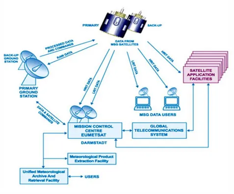
EUMETCast is a multi-service dissemination system for delivery the data to final users, together with Direct Dissemination. This is based on DVB-S technology (in transition towards DVB-S2 technology) based on a low cost reception stations concept (< 2K Euros). It consists of data providers and Service Provider (EUMETSAT), uplink provider (MediaBroadcast in Usingen), Turn around providers (Overon and Telespazio), commercial satellites (EUTELSAT EB9A, AB3, NSS806), reception stations and final users (see Figure 1).
Data Processing is not totally done in EUMETSAT, but Satellite Application Facilities (SAF) are used for de-centralized higher-level product generation since 1992. Typically, L1 (first processed) products are got via EUMETCast, then, the created L2 (re-processed) products are sent direct to EUMETCast uplink server for transmission. SAFs centers are distributed in Europe, such that the ability of EUMETSAT’s Member States to exploit satellite data is improved. Moreover, it facilitates cost-effective exploitation by ensuring that services are distributed in the most appropriate way.
6
Figure 1: EUMETCast [1]
2.3 Missions’ definition
The agency operates two types of satellites: Low Earth Orbit (LEO) and Geostationary (GEO) satellites, both at the operational centre in Darmstadt. While the operations are coordinated in Darmstadt, the ground stations are located around the world for the best satellite communications.
2.3.1 Low Earth Orbit (LEO) missions: MetopA and MetopB
The EUMETSAT Polar System (EPS) is the European contribution to the Initial Joint Polar System (IJPS) established with NOAA. EUMETSAT operates two EPS satellites: MetopA and MetopB which stay on the same orbit but phased in time, separated by 30 minutes relative to the nominal Local Solar Time.
7
Metop Satellites carry 13 instruments on board and travel along a Sun Synchronous orbit at 820 km. The missions were designed for a lifetime of about 5 years. On board autonomy is up to 36 hours, with on-board storage capacity of 24 GBit (EoL) sufficient for one orbit mission data. The Repeat Cycle is of 29 days and the cycle length of 412 orbits. The period is of 6081.5534 sec.
The ground stations used are located at Svalbard (Norway) and McMurdo (Antarctica). TM/TC are both done at SVALBARD for both the satellites, data acquisition is done in both the stations for MetopB, while for MetopA only Svalbard is used for this purpose (see Metop Visibility in Figure 2).
The EPS missions can be summarized as follow:
a) Local Mission: real-time transmission of imaging and sounding data to local user stations.
b) Global Mission: delivery of global sounding measurements to National Meteorological Services (NMS) of Member States, and to NOAA within 135 minutes of the instant of observation.
c) Search and Rescue (S&R) mission
8
Figure 2: Metop Traceability [2]
2.3.2 Geostationary (GEO) missions: MSG1, MSG2, MSG3
Meteosat second generation are geostationary satellites covering Europe and Africa. The mission is currently composed by three satellites and a fourth one that will be launched in 2015. These satellites ensure weather monitoring and are essential for ensuring safety of lives, nature and infrastructures. These satellites are very important for providing images in near real time, fundamental for critical storms or volcanic ash clouds, etc.
The satellites’ lifetime is expected to be of at least seven years each [3]. After the end of life of MSG satellites there is already a study in place for the Meteosat Third Generation (MTG) carried at EUMETSAT HQ.
The satellites are located at 36000 km above the equator. MSG3 is the prime satellite positioned at 0°, while MSG2 is at 9.5° East, and MSG1 is at 3.5° East.
9
MSG3 is providing Full Earth Scanning (FES) giving an image every 15 minutes; MSG2 is providing Rapid Scanning (RSS) giving an image every 5 minutes; while MSG1 is the backup satellite, normally in FES as well, but ready to cover for RSS when MSG2 has a problem.
The satellites carry on-board two main instruments: SEVIRI (Spinning Enhanced Visible and Infra-Red Imager) and GERB (Geostationary Earth Radiation Budget), which give images of Europe, Africa and North Atlantic.
The primary ground stations that are used for tracking the satellites are in Usingen (Germany). Moreover, Maspalomas supports the missions providing for one satellite per time, TM/TC and ranging (Maspalomas is not able to provide Raw Images). The back-up of Maspalomas is Cheia in Romania. Lately, new tests have been conducted with one antenna in Fucino (Italy) for testing the functionalities of the antenna when MSG4 will be in orbit and a fourth Antenna will be needed.
Figure 3 shows a representative scheme for communication from and to the satellite until the data distribution for MSG Satellites, including the SAF and final users.
10
2.4 Spacecraft Operations
2.4.1 Metop Operations
In order to understand the characteristics of Metop operations, the characteristics of the satellites orbit should be taken into account. In particular, remember that the satellites are in a near polar-sun synchronous orbit. The repeat cycle is of 29 days and the cycle length is 412 orbits. The period of the latter is 6081.5534 seconds. The satellites travels at a height of 822.250 km (at perigee) and of 849.516 km (at apogee), and with an inclination of 98.7022°.
For routine nominal operations, SVALBARD (Norway) ground station is used for TM/TC and GDS (global data services) data, which are collected via two Central Data Acquisition (CDA) Stations (see Figure 4). Visibility above the station is of about 10 minutes.
11
For critical operations for the Spacecraft’s health, such as emergency maneuvers, together with the Svalbard station also one of the three following Stations is used: Perth (Australia), or Kourou (French Guyana) or Fairbanks (USA).
In case of spacecraft anomalies, still Svalbard stays the main station. If there is co-visibility with other satellites, METOP has priority. Support is given also by Fairbanks (15 extra minutes of visibility).
As understood from above, Metop satellites are not continuously visible; this means that all the activities of commanding and dumping should be done within 10 minutes, which is the average length of the passes. For this reason, the spacecraft controllers should execute specific activities before, during and after the passes.
In particular, before the passes, there should be the planning/scheduling of the operations in non-visibility. Controllers should generate also TT-TCs and load them in the Mission Queue (MCS). Apart from extra commands or special commands, the other activities are normally planned and inserted in the Mission Planning and then executed automatically at a specific time.
During the passes they monitor the download of real-time Housekeeping Telemetry (HKTM), Reports Formats and Mission Data. There is the uplink of TT-TCs from the Mission Queue. Once the AOS (Acquisition of Signal) is received, there is the initial status assessment, and eventually decision and actions to do in specific cases. In case of anomalies, on-call support should be called immediately.
After the passes there is the full evaluation of acquired data (both platform and mission data) by Analysts and Ops Engineers. In case of anomalies, the latter have to take decisions on remedy activities relying in the spacecraft autonomy providing inputs to planning or controllers. In particular it should be kept in mind that satellites are designed such that they can survive even for some days without interventions from ground so within a limit there is no rush in intervening.
Special activities are LEOP (Lunch and Early Operation Phase) and Commissioning, but their interest goes behind the scope of this thesis.
12
2.4.1 MSG Operations
MSG operations carried at EUMETSAT control room (see Figure 5) are much simpler than Metop operations. MSG satellites, in being in a geostationary orbit are continuously visible from the Earth Ground Stations.
All the activities are again prepared in the mission planning and are loaded in the schedule. In case of anomalies or special test or emergency operations, controllers, with the support of analysts and engineers load commands to be sent to the satellites. For any other activity, included eclipse operations or manoeuvres, all the commands are in the queue and the role of the controllers is to monitor that no anomalies occur. In case of anomalies, as for the Metop satellites, engineers have to take decisions on remedy activities. Also for geostationary satellites, one should remember that the latter are designed such that they can survive even for some days without interventions from ground so within a limit there is no rush in intervening. Constrains on intervention are done from the thermal monitoring: satellites should recover as soon as possible for avoiding the temperature to be too high or too low as this would damage the spacecraft.
13
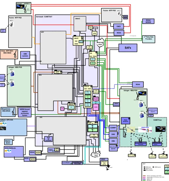
2.5 Multi-mission architecture
The functions of the Multi Mission Systems are provided by a number of elements, such as also a number of software tools and packages that are used commonly across the Multi Mission Systems. These common software tools and packages provide an infrastructure layer and ensure a common approach for activities that are common across the Operational Ground Segments. Although built into the programme specific systems, these tools and packages are maintained as part of the Multi-Mission systems. In addition to the facilities and S/W packages that comprise the Multi Mission systems, there are often duplicated versions that allow the facilities to be used in different modes. These duplicated facilities are termed environments and each facility may provide one or more of the following environments:
Operational (OPE);
Validation (VAL);
Development (DEV).
The Multi Mission Systems are composed of the components providing the functions that are common to more than one program – specifically, Archive and User Services, Dissemination, Monitoring and Infrastructure (see Figure 6)
14 Darmstadt - EUMETSAT Fucino - MTP PGS MET-7 MTP MSG Usingen - MSG PGS Usingen - MSG PGS MSG-2 LRIT D W D S AT /B M D à IODC -DCP's DCP's 0° MSG-1 EUMETCast MSG HRIT à Atlantic Bird NSS 806 OCN Maspalomas - MSG BRGS OPE-1 OPE-2 OPE-3 EPS OPE-4 UMARF EXGATE InputOutput Madrid Paris H RIT on ly DWD GERB Ground segment processing System CMS Lannion Media Broadcast GEOSAR Platforms 7 GEOSAR Ground Segment Telespazio Fucino ß Schedule data Internet users Overon OPE INGATE OPE-1 MTP/MSG/ JASON2/RMDCN OPE-2 VAL OPE-3 EPS OPE-4 UMARF EXGATE Input Output TCE CNES Cheia - MTP BGS - MSG SBGS JASON 2 EPS
Svalbard - EPS CDA
User station data IPPS NOAA GS EXTENSION TM Propagator Madrid - BUCC NODEW NOAA EO Portal MASIF OPE-1 OPE OPE-2 VAL INTERNAL EXTERNAL MSG-2 MSG-1 NASA WOTIS External users SAFs DVB C_BAND_Africa C_BAND_S.AmericaDVB DVB KU_BAND Fucino - MTP PGS MET-7 PDUS SDUS ECMWF Foyer UMARF Input Output Internet Server OPE1 OPE2 OIS Input Output
ß SAF Catalogue Data
Jason-2 NOAA Earth Terminal Usingen – JASON-2 Earth Terminal DCPF GEMS client SNI connection GEMS server SMART server Facility OPE Instance VAL Instance
FTP transfer from EXGate Nominal: Fibre, Back-up: Sat link Jason-2 Tunnel Nominal: Tunnel, Back-up: Ops Internet Nominal: EARS_IP VPN, Back-up: Ops Internet EARS_IP VPN RMDCN_VPN OPS Internet NOAA link Nominal: E1 , Back-up:SAT Link, ISDN
KEY IASI TEC CNES17 WASHINGTON TOULOUSE CLS ARGOS16 NASA-McMurdo CMA NOAA L-Band ESOC GRAS Aux. Data Service NOAA/ NESDIS METOP-A 3rd Party Data Providers NOAA-19 NETSAT PARDET EUM GSICS GSICS Partners Météo-France RETIM
15
3 Generic Event Monitoring Software – GEMS
3.1 General Requirements and functionalities
GEMS software was developed with the cooperation between TSS division and RSO division, in order to provide a common monitoring for the different programs running in EUMETSAT, i.e. for both LEO and GEO missions.
The system is based on several GEMS clients that send text events to the GEMS Server, where they are collected and stored. Data can then be accessed via an internet based browser interface or via HMI clients, both allowing real-time and history of events (see Figure 7).
GEMS is used for analysing log files sent from up 180 different EUMETSAT (and non-EUMETSAT) servers, processing over 2 million events per day.
GEMS is used within the EUMETSAT environments across operational components, but also it is visible to external partner organizations when monitoring is required. EUMETSAT hosts several machines where GEMS clients collect events, which are then forwarded to the GEMS Server. The events can come from log files, or be based on facilities processing events, or rise directly from monitoring tools or facilities. The GEMS Server is used for storage and archive of all generated events.
There are a few facilities, such as EXGATE or UMARF where the GEMS Servers are also their own Clients. This means that the GEMS processes are run for monitoring a specific facility and then are sent to the central Server communicating the output. Users access the data through a dedicated web based HMI, which allows both real time and history of data. In addition, it is possible to subscribe to a notification system for periodical notifications via e-mails or HTTP request, both within EUMETSAT buildings and outside.
GEMS is expected to collect events from operational servers and workstations in the Operations system.
16
Figure 7: GEMS Functional Components diagram [6]
3.1.1 Software building
The language used is JAVA, because of the facility and the speed of development, also because of the availability of reusable components, and above all because it is simple to deploy across multi-platform Environments (See Annex A for the used Java packages) [6].
An API (Application Programming Interface) is provided, for C and Java, to enable GEMS Events to be raised within facility application software. Also for UNIX and Windows a set of GEMS process control scripts is provided. The database instead is done using the SQL structure; in particular two databases are implemented: Oracle and Apache Derby.
A few agents have been implemented, such as the real-time monitoring of log files, file system usage monitoring, etc. More agents can be added when required. The GEMS agents are background processes with no manual intervention, it is then important to check the stability, the memory consumption and the CPU usage.
17
The following java processes make up the GEMS server side Graphical User Interface (GUI) hosting:
GEMS MMI contains the web files (.xhtml, .wav, .png) for the MMI.
Apache Tomcat 6 in order to allow processing of Java Server Faces (JSF).
In order for a browser to support the GEMS Human Machine Interface (HMI), it should have the following characteristics:
It must be set to enable Javascript and be capable of handling http GET/POST requests as well as the XmlHttpRequest (AJAX)
It should support HTML5 audio tag or plug-in that enables the playing of sound files of type audio/wav and audio/mpeg.
The code was written and is maintained in the Eclipse environment and is supported by the following platforms:
UNIX –AIX, HP, ... Linux (RedHat, SuSE) SUN Solaris x86 Windows
3.1.2 Event storage
Operations require that no monitoring events are lost. As such, the events created on a client are not only locally stored, but they are also forwarded to the GEMS server. The write access to the files is secured by a file-locking mechanism. The last byte position in each file is stored in a modification (mod) file, which is always available in the same position even after a restart from a reading process.
Certainly GEMS events are stored in files (called “facility log files) according to the facility name of the events where a housekeeping mechanism is applied in order to avoid that they grow too large. Furthermore, this mechanism renames the existing facility log file and creates a new one with the facility name.
18 For example if we have a file named as
EXGATE.log file
then the housekeeping mechanism would rename the file as following: EXGATE.YY.DDD.HH.MM.SS.mmm.log
where it is added the default timestamp in the format according to Table 1 [6].
3.1.3 GEMS Agent Classes
3.1.3.1 CheckEventAgent
One of the most used tasks is the GEMS CheckEventAgent. This is an optional internal task of the server whose main function is to search for expected events in the database and raise events against rules, in particular it is possible to detect if certain events have not been generated for a given time period with respect to the current time. The process uses filter rules for operating. First of all the rule defines the facility for which the events should be searched, then it defines the regular expression that should be used for searching the events, then the severity of the events to match (if it is a warning, an alarm or a normal message). Moreover, it specifies the host and the process of the events to match and the destination facility. Last important check is regarding the time, and in particular the maximum time allowed for matching an event before raising an alarm, and the minimum permitted time between two alarms for the same rules [1].
For each rule, the following processing sequence is applied: Create and execute query for the rule
If no events are returned
If no delay is set or if the delay has expired Raise GEMS Event
Else
19
Abbreviation Meaning
YY year, e.g. 10
YYYY year, e.g. 2010
MM month, e.g. 11
Dd day, e.g. 29
DDD day of year, e.g. 243
HH hour of the day, e.g. 16
Mm minutes, e.g. 03
Ss seconds, e.g. 55
SSS/SSSS/SSSSS/SSSSSS fractions of second up to microseconds precision,
e.g. 479, 342131
‘T’ Literal “T”
Table 1: Nomenclature for GEMS events timestamp
3.1.3.2 Log File Agent
The LogFileAgent is an optional, client based, agent daemon process, whose task is to search for specific log files for key words and raises events when it finds any, as follow1:
if the read line contains a certain keyword from a positive list. if the line does not contain any keyword from a negative list.
The checking can then be done against a positive or a negative list and the behaviour can be summarized as follow:
Contain: if at least one keyword is contained in the line of the file in a positive list will generate events, while the other lines that do not include the keywords will be ignored.
Ignore: if none of the keywords are contained in the line of the file in a negative list will generate events.
Contain/Ignore: it is a mixed case of positive and negative list. The process searches for positive keywords, but if it contains at least one negative keyword, the event will be ignored. This is a useful process for example when searching for the keyword “error”, but ignores specific errors that should be reported, such as “error 409”.
20
Ignore/Contain: it is a mixed case of negative and positive list. The process searches for negative keywords, but if it contains at least one positive keyword it sill report the event. This is a useful process for example when the messages containing “info” are ignored but those containing “important info” are reported.
3.2 Operative GEMS v. 3.6
3.2.1 GEMS Man Machine Interface (MMI)
The users access GEMS events in real time and the history via the GEMS Man Machine Interface (MMI). The events are sent from the GEMS Clients to the GEMS Servers, which also host the Web application providing the MMI. In particular, the events are first stored in a database by the GEMS Server and then are sent to the GEMS MMI for live display, where alarms, warnings and info are shown to controllers, engineers and external partners.
The GEMS MMI was built using standard JavaServer Faces (JSF) pages and the enterprise User Interface (UI) framework Prime Faces. The server and the browsers communicate using the Atmosphere library included in PrimePush (extension of Prime Faces), finally resulting in a standard Web page in HTML/CSS/JavaScript [7].
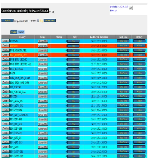
3.2.3 GEMS Graphical User Interface (GUI)
The GEMS Graphical User Interface (GUI) can be accessed online at the EUMETSAT website (http://masif.eumetsat.int/GEMS/) using specific username and password.
The page is accessible from the control room by the spacecraft controllers, by the users within the EUMETSAT infrastructure and by the external users. In the main page (see Figure 8), the top right corner shows regularly the connection check, displaying the time of the last check and the status of the connection (Status: OK means that there have not been interruption in the connection). The top left offers a
21
refresh button for re-loading the page, a printing button, the Help link and the possibility of managing filters (although the latter can be defined in other ways that will be explained below).
The table shows eight columns: Disable Facility
Facility Name Sound
Alarms Filters
Last Event Reception Real-Time
History
22
3.3 The multi-mission operations tools
3.3.1 Facilities monitoring
At EUMETSAT Operation center there are four Geostationary satellites (3 MSG and 1 MTP), two Metop satellites and furthermore two American satellites (Jason2 and NOAA 19) are monitored in the LEO control room (although no commanding is allowed). EUMETSAT is not only operations, but there are several system that are around these satellites, which can be the archiving centers, the image processing facility (IMPF), the Extraction Facility (MPEF), etc. The facilities should all be connected between them, such that it is easy to communicate and to control. For this reason, EUMETSAT promoted the Multi Mission Element (MME) Monitoring. The hardware of the monitoring system is called MASIF (Monitoring And Support Infrastructure Facility), whose operational platform can be accessed online (www.masif.eumetsat.int). The software is composed by the following elements:
GEMS SMART SPRS SMS GMC/NAGIOS 3.3.2 MASIF
The hardware provides centralized monitoring, analysis and reporting portal for ground segment facilities, instrument performance and product quality.
As shown in Figure 9, MASIF can be thought like a big box where GEMS Server, SMART Server and SPRS are located. The GEMS Clients send the events to the GEMS Server and to the GEMS Server Relay. From the GEMS Server they are sent to the SMART Server and from here to the SPRS. From the SMART server, the Daily Logs, the Reports and the OSSI (Operational Service Status Indicator) are generated.
23
Figure 9: MASIF Hardware [1]
MASIF is composed by two chains: OPE 1 and OPE 2. OPE 1 represents the operational environment, while OPE 2 represents the validation environment. In particular OPE 2 is used for validating procedures, software and data units; OPE 2 is also configured as back-up for OPE 1: this means that it is connected for real time operations, although it is not normally able to send commands to the satellites, but in case of emergency, an OPE 1–OPE 2 swap is available and OPE 2 can become operational substituting OPE 1.
Each chain has two clusters, one is used for internal purpose (e.g. in control room), while the second one is used for external purpose (e.g. for on-call support outside working hours).
Figure 10 represents the MASIF architecture. Starting from the left side and going to the right the picture shows the reception from the satellites until the final delivery to the users.
24
Figure 10: MASIF architecture [1]
When the data are received from the satellites via the first firewall they arrive to MASIF internal (see the Processing clusters). Already the two OPE and VAL chains (above defined as OPE 1 and OPE 2) are visible. Afterwards, the second firewall data are transferred to MASIF external (see the Publication clusters). Lastly, after the third firewall, the data are available on internet for the external users.
MASIF environment can be accessed on-line as follow: - www.omasif.eumetsat.int, which represents OPE INT - www.vmasif.eumetsat.int, which represents VAL INT - www.omasif.eumetsat.org, which represents OPE EXT - www.vmasif.eumetsat.org, which represents VAL EXT The name structure is as follow:
OMASBBnn
Where O stands for Operational environment (OPE 1 and OPE 2), MAS marks the facility, BB indicates if it is MASIF internal (IS) or external (ES), and the nn are two numbers which indicate if the data are from operational or validation environment (01 is for operational and 11 is for validation).
25
The blue page represents the operational environment website, while the green page represents the validation environment website (see Figure 11).
Figure 11: MASIF websites: the left one, in blue, represents the operational environment, while the right one, in green, represents the validation environment [1].
3.3.3 SMART
One of the software used for the Multi Mission Elements is SMART (Scheduling, Monitoring, Analysis and Reporting Tool). As mentioned above, its functions are based on the “communication” with GEMS software from which it receives the events. This software can be considered as the interface between the near-real-time monitoring and the reporting.
The SMART tool can be configured for any mission and for any facility. The software is based on schedules that are examined with back-processes that compare what is received with what is in the schedule. Normally on each Monday morning, the schedules are generated for the following ten days. It is also possible to run the schedules manually (in case an update is done during the week and there is the necessity of applying the new schedule immediately and not wait the next Monday). The Smart Server runs continuously checking for GEMS logs to match using regular expressions. The information from the logs are extracted using defined mapping. Once the events are analysed and match (or not) with the schedule, then the latter is updated with the information. Using the drill-down capability, the Smart Viewer displays the
26
contents of the schedule files in a table format (see Figure 12). When all the files are received then the display is grey, when there are missing files, the box is coloured in red (Smart Alert), while the white means that the files are coming in and some time is still required before verifying if the files arrived or not.
From SMART, the SMART daily logs are generated: this mechanism extracts information from the schedule file and generate text files that are disseminated on EUMETCast. In a similar way the OSSI extract information and update the web page traffic light (see Figure 13).
Figure 12: SMART Viewer showing missing files
Figure 13: OSSI, Service Status Indicator indicating that all the services are ok but the NOAA-19, which is shown in red.
27
3.3.4 SMS
SMS (Supervisor Monitor Scheduler) is the viewer interface for the near-real-time monitoring and in-house control. It is not configured for specific missions, but for multi-mission processes.
Its functionality is based on the monitoring and control of the processes running in the multi-mission clusters. In particular, it checks the alarms, the colour code and sound, manuals, and also the start, stop and testing of specific processes (see Figure 14).
Figure 14: SMS showing METOP pushed to EUMETCast per level and product
3.4 User Concept
GEMS activities can be seen by different users with different purposes, which imply different configurable access rights for each group. In particular, the end users are:
Spacecraft Operations Controllers
28
External Partners (MeteoFrance, NOAA)
Operations Administrators
The main users of GEMS are the Spacecraft Operations Controllers. They require a dedicated GEMS workstation with a GEMS client HMI permanently visible. They react to any alarm raised by the system and provide a first line analysis. They can perform some very high-level configuration such as setting filters. Operations components have different controllers requiring their own unique view of GEMS:
─ MTP (Meteosat Transition Program, 1st Generation) ─ MSG (Meteosat Second Generation)
─ MTG* (Meteosat Third Generation)
─ EPS (Eumetsat Polar System – Metop, NOAA) ─ EARS (Eumetsat Advanced Retransmission System)
─ OSTM (Ocean Surface Topography Mission - JASON2, 31, Sentinel1, Oceansat1)
─ UMARF (Unified Metrological Archive and Retrieval Facility) ─ S31 [1] (Sentinel-3)
The other main users of GEMS are the Operations Analyst and Engineers. They support the operations controller teams by providing further analysis of GEMS events. They also use GEMS to monitor the system during critical activities. They require the ability to view GEMS both onsite and offsite of EUMETSAT.
Under agreement with EUMETSAT, some external partner agencies require a GEMS viewer restricted to only information that is applicable to them. They may also perform some high-level configuration. By nature of their role, they require access from GEMS offsite from EUMETSAT.
29
Last but not least, there are the operations administrators that are responsible for the overall configuration of GEMS, and for test and acceptance of new GEMS software versions. They require full access to GEMS configurable items.
4 GEMS v. 4.4
4.1 Redesign causes
The current operational GEMS software v. 3.6, despite the overall good performances, has a few limitations.
First of all, the MMI is implemented using standard Java Server Pages (JSP) and heavy use of direct Java code and it is based on the processing of ASCII files for filters and display of events. Direct consequence is that for any update it is required to reload the full page, making the website slower and heavier.
The current MMI can be classified as server-side dynamic web-page which allows only a limited amount of interactivity.
During the years of operations, also several anomalies have been identified that are limitations of the software and can be solved with a new release. In the following are reported the main ones.
Occasionally it happens that when a GEMS alarm is received and the “real-time” button is clicked to bring up the alarm text, the viewer instead displays a different event (warning or information).
An alarming GEMS facility can be muted by pressing the 'Sound=ON' button.
This button then turns yellow and changes description to 'Sound=OFF'.
This function is available from the GEMS Main Page for each facility and also from the Real-Time Events Window for each facility.
If the sound is turned OFF or ON from the Real-Time Event Window then the button on the Main GEMS Page also changes with.
But if the Sound is turned OFF/ON from the Main Page the button on the Real-Time Event does not change.
30
If the Sound was turned OFF from Real-Time Event Window and this window was closed after checking the alarm then the status of the Sound OFF/ON button is set to the last status of what was set on the Real-Time Event Window at each refresh (every minute) of the Main Page. This can lead to automatic switch OFF of the audible alarm of a GEMS facility without notice by the controller and therefore alarms can be missed.
When using the "^" character in a regular expression in a GEMS viewer search
then the regular expression returns incorrect or no results if the “^” character is not followed by a wildcard expression like ".*" (dot-star).
If used without wildcards the GEMS viewer does not return any result although there are GEMS events starting with the text followed by ^-character. Example: The reg. expression ^GTS_IN-SSMI.*Received$ does not return any GEMS events but the reg. expression ^.*GTS_IN-SSMI.*Received$ returns the correct GEMS events. The regular expression works correctly when used in a CheckEventAgent.
Currently the filter management on GEMS allows inputting filters per facility
either from a filter file or manually. Filters are then added to a filter list. Both methods allow setting a duration after which the filter expires. However the GEMS system only takes the duration from the last filter set and overwrites the duration to all other filters in the list. This can cause filters with shorter expiration than the last one to stay in the list and alarms will be missed. Moreover the current filter duration cannot be checked after the filter was input. This results in filter activities not being tracked and alarms to be missed.
GEMS freezes when disabling many facilities. It is required to have a “Disable
all” button.
The pre-set filters used by MSG controllers for EXGATE, MSG_CF,
SMART_OPE_GEO and UMARF MET7 eclipses are visible to Meteo France (RETIM) when "Filter Manager" is selected. This means that the internal settings are actually visible to external partners.
31
The GEMS server is presently permanently polled for new events by the
GEMS client, which results in an excessive server load.
GEMS sometimes shows a "service temporarily unavailable" screen rather
than the usual GEMS viewer (see Figure 15).
Figure 15: Service unavailable
4.2 New features
The new release mainly contains software changes to address the mal-functionalities mentioned above. Moreover, it includes some new features for improving the software [8].
The solution was a full re-implementation of the GEMS MMI following a rich web application approach, adjusting and optimizing the GEMS MMI for faster response times and also offers specific MMI elements for mobile devices in order to facilitate on-call support.
The main points have been:
32
Development of a database backend for user management, permissions, preferences, stored queries, etc.;
Show real-time alarms view with enhanced acknowledgement and notification features;
Allow query engine for historical searches including auto-refreshed open-ended queries;
Allow extended possibilities for exporting and sharing events;
Existence of a notification system for immediate and periodical notifications via emails or HTTP requests;
Availability of filter management system with group sharing and server-side storage;
Sound management system supporting MP3 and WAV with sound coordination between windows of the same group;
Online help.
4.3 MMI Implementation
The GEMS MMI has been integrated as an additional module into the GEMS Server package. This approach allowed the direct interaction of the MMI with the GEMS data access layer and removed the need to use the networked endpoints between processes (see Figure 16).
33
Figure 16: MMI Architecture Overview [9]
The GEMS MMI is intended as a web application that in order to store data efficiently makes full use of data caching and data scopes. The MMI implementation can be divided into the following main categories:
Backend, which contains the business logic and data processing;
Frontend, which provides the elements that are shown in the browser and interact with the user;
Administrator and User Management, which is used for the storage of authentication and user preference information related to the MMI;
Data Query Extensions, which covers the more advanced query features required by the MMI, including all of the currently available filtering requirements.
GEMS MMI was thought as a clear MVC (Model, View and Controller) (see Figure 17) type of application. As such, the Backend is the foundation of the Model, while
34
the Frontend extends on the Model and provides the View and Controller implementations. In the following, the four categories are explained.
Figure 17: Model View Controller [10]
4.3.1 MMI implementation: Backend
The task of the Backend is to manage all data processing and state of the respective clients that are accessing the GEMS MMI. In order to do that, the following components are used:
Event Dispatcher
Client Session(s)
View Manager(s)
Event Query Manager
Notification Manager
The Event Dispatcher runs immediate processing on the events that receives by the GEMS server. This processing is also mapped by the corresponding knowledge base rules. Each event is then forwarded to each individual Client Session (for Real Time Events), which represents a specific user session and corresponding setup of the GEMS MMI. These events are then used to populate the alarm count in the facility overview and for keeping track of the unacknowledged alarms per facility.
35
A Client Session represents a logged-in user in GEMS and manages the currently logged-in user, permissions, alarming counts and other state information. In addition, it manages the user’s preferences and setting via the Authentication and Configuration Manager. Each ClientSession is related to a Servlet session and as such an open browser.
Each ClientSession instance contains post-processing routines, which can modify the events displayed to the users:
Apply facility filters;
Knowledge-Base Article Mapping.
When there are more than one GEMS MMI window in the same browser, they will be run the same session and the View Manager contains the information for distinguishing between the different open windows (e.g. for applying different filters in two different tabs).
The history view for a specific time period is allowed thanks to the Event Query Manager. In particular in the new MMI, this will support the “open-ended queries” which will give the update of the page with real time events coming in.
It is also possible to send notifications, such as e-mails containing alarms. This is done thanks to the Notification Manager. The latter also has an extension interface in order to add other notification mechanisms in the future via configurable HTTP requests, such as logbook[9].
4.3.2 MMI implementation: Frontend
The implementation of the frontend is done following the JSF specification:
Design templates that contains JSF, HTML, CSS, etc., which define the visual appearance and view logic;
Backing Beans containing the Controller and thus the interaction logic for working with the data in the model and controls shown in the View.
36
The user interface can be used across multiple browser tabs for the display of different functionalities. If the corresponding functionality is configured for a user (e.g. for users belonging to the Controller User Group), a confirmation dialog is presented when trying to close any of the tabs.
Each GEMS view contains information about the currently logged in user, the server connection state to the GEMS MMI server and the GEMS version in the top-right corner. The connection state of the MMI to the underlying server is monitored via JavaScript, thus removing the need for an Applet.
Each GEMS window on the main screen has a navigation (menu) bar on the top of the screen, which allows fast access to the respective functionality. It offers the following navigation items:
Facilities: provides the “Facility Overview” screen, which shows alarm statistics and quick access for the currently enabled facilities.
Administration (only shown for administrator users): allows access to the “Administration” set of functionalities as described below.
Query: provides access to the event query view. This view can also be opened pre-configured from the facility overview by clicking the “Query” button next to a specific facility. Opening the Query view via the navigation menu will open a query window with the default values set up (e.g. number of events displayed per result page).
The facility overview, despite the new design, offers similar items to the ones currently implemented in GEMS v. 3.6. The following information are shown in the webpage (see Figure 18):
Facility Name;
Last Event Time, at which an event has been received for this facility;
Sound controls;
Number of Alarms;
37
Monitoring status
Per-facility filters.
In the new software, the facilities can be grouped by environment, Operations and Components in a tree-structure, easily visible by the arrow on the left of the facility box and a ∑ symbol next to the box in the Alarms column (see Figure 18).
Figure 18: GEMS tree structure
Depending on user permissions, it is possible to persistently hide or show facilities (individually, in bulk or all at once) in this list. The user can also reset this list to the full list of facilities that the user (or any of the groups the user belongs to) has access to by selecting and enabling all disabled facilities.
As in v. 3.6., the list of disabled facilities below the active facilities list can be toggled on or off by clicking the “Disabled Facilities” label and is hidden by default. The disabled facilities can be found clicking on the “disabled facilities” bar (see Figure 19).
38
Operators have the possibility of disabling audible alarm notifications for a specific facility or the complete list of facilities. Disabling is done for a limited time that is configurable by the operator. Alarming will be re-enabled automatically after this period. The default for this period is 10min (see Figure 20). A record will be kept indicating whenever an alarm has been disabled, tracking the time at which the disabling took place, its length, what facilities were affected and the responsible user (see Figure 21) . This record can be seen by administrators.
Figure 20: Disabling sound
Figure 21: Disabled sound countdown to expire
The user profile view allows the user to view and configure the user’s general data (see Figure 22). This includes:
Changing password;
Viewing/changing real name and e-mail (the latter for notifications);
39
Figure 22: User Profile page
The user can also access and edit the current user preferences (see Figure 23) directly or, alternatively, override the current preferences with the default preferences from one of the groups the user belongs to via the “Restore Group Defaults” button.
Figure 23: User preferences page setup
Also, the user can define its own facility-grouping (see Figure 24) and the notification settings [9].
40
Figure 24: Facility grouping user setup
4.4 MMI implementation: Administrator and User
Management
The administrator view is only accessible to administrators and has as a main function allowing the creation, removal and editing of user accounts and user groups. For the latter, the administrator is able to configure the user list and the default preferences of each group.
The administrator webpage is used also for managing the Knowledge Base Mapping and the notifications. In addition, the filter records for each user are visible and also the Alarm Suppression Records (see Figure 25).
The mapping of events to knowledge base articles is achieved via rules containing the following information: Rule ID (0..n); Facilities (0..n); Event severities (0..n); Regular expressions (1..n); KB article title; KB article link.
41
Each incoming event, matching the defined severities, will be checked for the regular expressions. Each event will be augmented with the knowledge base rules it matches. Notifications can be triggered either per event matching the specific rule definition or aggregated for a defined time period. Furthermore, notifications can be sent either via e-mail to a specified e-mail address or via HTTP to an external system, e.g. an electronic logbook.
Figure 25: Administrator page
The User Management view in the Administration panel is providing access to users and group definitions. For the users, the following fields can be defined (see Error!
eference source not found.):
Login Name: which is the name used for logging in or to be specified for automated login.
Full Name: which is the full name of the user for information purposes.
Password: which can be changed by administrators or by the user via its user profile. Should a user forget a password, then an administrator can reset it via the user management.
![Figure 1: EUMETCast [1]](https://thumb-eu.123doks.com/thumbv2/123dokorg/7455837.101374/19.892.206.763.125.454/figure-eumetcast.webp)
![Figure 4: SVALBARD ground station [5]](https://thumb-eu.123doks.com/thumbv2/123dokorg/7455837.101374/23.892.224.752.632.1043/figure-svalbard-ground-station.webp)
![Figure 7: GEMS Functional Components diagram [6]](https://thumb-eu.123doks.com/thumbv2/123dokorg/7455837.101374/29.892.225.747.171.464/figure-gems-functional-components-diagram.webp)

![Figure 9: MASIF Hardware [1]](https://thumb-eu.123doks.com/thumbv2/123dokorg/7455837.101374/36.892.235.739.152.488/figure-masif-hardware.webp)
![Figure 10: MASIF architecture [1]](https://thumb-eu.123doks.com/thumbv2/123dokorg/7455837.101374/37.892.258.716.122.422/figure-masif-architecture.webp)
![Figure 11: MASIF websites: the left one, in blue, represents the operational environment, while the right one, in green, represents the validation environment [1]](https://thumb-eu.123doks.com/thumbv2/123dokorg/7455837.101374/38.892.191.779.192.449/figure-websites-represents-operational-environment-represents-validation-environment.webp)
