Research Article
Refined Rigid Block Model for In-Plane Loaded Masonry
Daniele Baraldi , Claudia Brito De Carvalho Bello, and Antonella Cecchi
Universit`a IUAV di Venezia, Terese, Dorsoduro 2206, Venezia 30123, ItalyCorrespondence should be addressed to Daniele Baraldi; [email protected]
Received 15 July 2020; Revised 12 September 2020; Accepted 15 September 2020; Published 29 September 2020 Academic Editor: Filippo Ubertini
Copyright © 2020 Daniele Baraldi et al. This is an open access article distributed under the Creative Commons Attribution License, which permits unrestricted use, distribution, and reproduction in any medium, provided the original work is properly cited.
In this work, a refined rigid block model is proposed for studying the in-plane behavior of regular masonry. The rigid block model is based on an existing discrete/rigid model with rigid blocks and elastoplastic interfaces that already proven its effectiveness in representing masonry behavior in linear and nonlinear fields. In this case, the proposed model is improved by assuming rigid quadrilateral elements connected by one-dimensional nonlinear interfaces, which are adopted both to represent mortar (or dry) joints between the blocks and also to represent inner potential cracks into the blocks. Furthermore, the softening behavior of interfaces in tension and shear is taken into account. Several numerical tests are performed by considering masonry panels with regular texture subjected to compression and shear. Particular attention is given to the collapse mechanisms and the pushover curves obtained numerically and compared with existing numerical and laboratory results. Furthermore, the numerical tests aim to evaluate the applicability limits of the proposed model with respect to existing results.
1. Introduction
Masonry is a heterogeneous structural material made of natural or artificial blocks connected by dry or mortar joints. Due to the large amount of masonry historical buildings that may be found in Italy and in other south European countries and considering the frequent seismic events in such areas, the assessment of the behavior of masonry and the devel-opment of numerical models for masonry structural ele-ments or buildings is an active field of research in Architecture and Civil Engineering.
Among the different numerical strategies that are fre-quently adopted for studying masonry and that may be found in literature [1–3], this work mainly focuses on a rigid block model, together with a finite element (FE) model based on a total rotating strain crack approach (FE-TRSCM) as-sumed as a comparison for some numerical tests. The first model may be considered a micro or local model, while the latter may be considered a macro or diffused model. A comparative analysis between the numerical models and a comparison with experimental results allow to perform a multiscale analysis of masonry behavior and to validate the new proposed model.
Rigid block models are based on several hypotheses that are typical of the wide field of discrete approaches. In this field, the discrete element (DE) model or method is the most common tool adopted in solid and structural mechanics. In general, DE models are characterized by the definition of elements and contacts between the elements. Following the original definition of the method [4–6], a DE model focuses on specimens composed by indepen-dent elements, which may be subjected to large dis-placements, and with a continuously updated determination of the contacts between the elements during a numerical test. DE approaches may be suc-cessfully adopted for studying masonry, thanks to its heterogeneity, and several models based on the DE method, originally introduced for soil and rock me-chanics, were extended to masonry mechanics [7].
In literature, numerous discrete models based on elastic [8–11] or shear deformable [12] blocks, connected by zero-thickness nonlinear interfaces are present, also considering cyclic loads [11]. Furthermore, in the field of discrete modeling for masonry, comparisons between such models and the continuous ones are frequently done [13, 14], also by performing multiscale approaches [15].
Volume 2020, Article ID 8844759, 13 pages https://doi.org/10.1155/2020/8844759
The rigid block model adopted here is particularly suitable for studying historical masonry, since it considers blocks as rigid bodies and dry or mortar joints as nonlinear interfaces. It is based on the original numerical model in-troduced by Cecchi and Sab [16], which follows small dis-placements hypothesis. Hence, it considers independent elements in contact, but it does not update the contact topology during numerical tests, given that small dis-placements are assumed. This contribution was extended to the field of material nonlinearity adopting a tension strength criterion and a Mohr–Coulomb yield criterion for restraining interface actions [17]. Such updated model was still based on small displacement hypothesis, which can be considered reasonable for masonry even in case of nonlinear behavior. Furthermore, no contact detection algorithms were proposed, allowing to obtain fast numerical solutions by means of a stiffness matrix approach, which turned out to be an advantage with respect to more general DE models extended to masonry. The resulting nonlinear rigid model turned out to be similar to the rigid block models adopted for performing limit analysis of masonry [18–22]. However, the original nonlinear rigid block model was able to perform pushover tests in load control, but it was not able to re-produce the softening behavior typical of masonry, given that it considers an elastic-perfectly plastic interface be-havior, which does not respect the actual response in tension and shear typical of mortar joints. However, this preliminary nonlinear rigid block model was calibrated for modeling in-plane loaded masonry panels with dry joints [23–25], showing a good agreement between more refined DE models, namely the combined finite element-discrete ele-ment (FE-DE) model [26], and laboratory results.
In this contribution, the new aspect introduced for improving the original rigid block model regards the adoption of a softening law in tension and shear for rep-resenting the postelastic behavior of mortar joints and the potential cracking of the blocks. In this latter case, a new inner block joint type is introduced, by subdividing each block into two half blocks, in order to simulate the potential cracking of the resisting elements due to tension and shear. This last aspect was already considered by other authors for better modeling masonry behavior in case of elastic blocks both in- and out-of-plane loaded [8, 10, 11] and also in case of rigid blocks [27] by performing limit analyses.
Focusing then on FE models for masonry, among the different models that may be found in literature, two main approaches may be considered: micro- and macro-modeling [28]. The first approach envisages the use of standard het-erogeneous FE models, with joints and blocks modeled by different materials and specific FEs, or with joints often modeled by means of zero-thickness interface elements [8, 29]. The second approach envisages the definition of a continuous material equivalent to the heterogeneous one, modeled by a unique type of FE. In this case, homogeni-zation approaches may be adopted by identifying a periodic cell typical of the masonry material and by adopting local linear and nonlinear mechanical parameters [30–33], also by performing multiscale analyses [34]. In particular, multiscale approaches are focused on Cauchy or micropolar/nonlocal
continuum models [35–39]. Another possibility in the field of continuous modeling is an approach based on the eval-uation of the overall properties of a masonry assemblage by fitting experimental tests. Orthotropic and also isotropic damage models are often adopted for this purpose [40]. Focusing on damage models, discrete or smeared crack approaches may be adopted by extending existing models originally introduced for modeling concrete material. The continuous total strain crack model (TSCM) is a proper tool for modeling strengthened masonry structures [41–43] and homogenous isotropic materials as rammed earth masonry [44, 45]. Moreover, it has also been adopted for modeling unreinforced masonry panels under in-plane loads [40, 46, 47]. An interesting comparison between several numerical finite element models for the assessment of the behavior of unreinforced masonry has been performed by Bartoli et al. [48], also considering the performance of the total strain crack model.
This work is dedicated to the assessment of the nonlinear behavior of masonry panels with regular texture subjected to vertical and horizontal in-plane actions. The aim of this work is to validate the proposed improvements of an existing rigid block model by performing several numerical tests and comparing the results of the updated model with respect to existing laboratory results and other accurate numerical results. The calibration already performed by the authors for rigid, FE/DE, and FE-TRSCM models [49] is extended to the case of the updated rigid block model. Before performing tests on masonry walls, the nonlinear behavior of mortar joints is evaluated for first by performing some numerical tests on two blocks specimens. Then, the experimental campaign by Raijmakers and Vermeltfoort [50] on almost square-shaped masonry panels is taken as reference, together with the work of Lourenço and Rots [8], that studied the same panels by means of FE models with interface elements. Such case studies have been recently considered by the authors in a comparison between continuous and discrete models focusing on nonlinear behavior [51] and by other authors in a similar comparison by means of a multiscale/ multimodel approach [15]. Here, the pioneering work of Page [29] is also taken into consideration as a further case study.
The paper is organized as follows: the numerical models adopted are introduced, focusing on the updated rigid block model; then, the case studies considered are described, and the results of the numerical tests performed with the adopted models are showed and discussed, accounting also for laboratory results. Some comments and possible future developments are presented in the final part of the work.
2. Numerical Models
2.1. Refined Rigid Block Model–Geometry. A one-leaf ma-sonry panel with regular texture and following the so-called “running bond” pattern is considered (Figure 1(a)). Block dimensions are width b, height a, and thickness s, whereas mortar joint thickness is e, which is assumed to be equal for both head (vertical) and bed (horizontal) joints. A refined rigid block model is defined by introducing rigid elements
coincident with one half of each actual resisting element, hence having width b/2 and height a (Figure 1(b)). The resulting discretization is characterized by half blocks aligned both horizontally and vertically and in contact with four neighboring half blocks by means of four interfaces coincident with the four half block edges. Horizontal in-terfaces are always represented by mortar inin-terfaces, whereas vertical interfaces can be, alternatively, mortar interfaces or inner block interfaces; the latter interface case may represent a potential vertical crack for the original block, which can be obtained in case of a compressive action on the masonry structure without or with a contemporary shear action.
Assuming a two-dimensional coordinate system Oy1y2, a
plane stress state, and considering the hypothesis of rigid elements and small displacements, the in-plane displace-ment of each half block Bi,jis a rigid body motion defined by half block center in-plane translations uij= {u1u2}Tand half
block in-plane rotation ω3,ijwith respect to its center: u(y) � uij+Ωijy − yij, (1)
where Ωij= skw (ω3,ij). Nodal degrees of freedom of a generic
element can be collected in a vector qij� u 1u2ω3
T ij.
The interactions between the half blocks through the interfaces are represented by the resultants of the corre-sponding contact stresses, which are given by a normal force Fn, a shear force Fsand a bending moment M: floc= {FnFsM} T, which are defined considering the local orientation of the interface. The corresponding interface actions in the global coordinate system are f = {F1 F2 M}T= R floc, where R is the
rotation matrix of the interface depending on its horizontal or vertical orientation. Such interactions depend on the relative displacements and rotations between adjacent half blocks, defined as d = {d1 d2 δ}T, which can be written in the
form of local relative displacements dloc= {dn ds δ}T depending on interface orientation, d = {d1d2 δ}T= R dloc.
These relative displacements can also be written as a function of half block global displacements in vector form by in-troducing a compatibility matrix H detailed for each block and collecting the distances between each half block center and interface center:
d � Hq � H ij Hhk qij qhk , (2) with Hij� −Ι + Dij� −1 0 k1a 2 0 −1 k2b 4 0 0 −1 ⎡ ⎢ ⎢ ⎢ ⎢ ⎢ ⎢ ⎢ ⎢ ⎢ ⎢ ⎢ ⎢ ⎢ ⎢ ⎢ ⎢ ⎢ ⎢ ⎢ ⎢ ⎢ ⎢ ⎢ ⎢ ⎢ ⎢ ⎢ ⎢ ⎢ ⎢ ⎢ ⎢ ⎢ ⎢ ⎢ ⎢ ⎢ ⎢ ⎢ ⎢ ⎢ ⎢ ⎢ ⎢ ⎢ ⎢ ⎢ ⎢ ⎢ ⎢ ⎢ ⎢ ⎢ ⎣ ⎤⎥⎥⎥⎥⎥⎥⎥⎥ ⎥⎥⎥⎥⎥⎥⎥⎥ ⎥⎥⎥⎥⎥⎥⎥⎥ ⎥⎥⎥⎥⎥⎥⎥⎥ ⎥⎥⎥⎥⎥⎥⎥⎥ ⎥⎥⎥⎥⎥⎥⎥⎥ ⎥⎥⎥⎥⎥⎦ , Hhk�Ι + Dhk� 1 0 k1a 2 0 1 k2b 4 0 0 1 ⎡ ⎢ ⎢ ⎢ ⎢ ⎢ ⎢ ⎢ ⎢ ⎢ ⎢ ⎢ ⎢ ⎢ ⎢ ⎢ ⎢ ⎢ ⎢ ⎢ ⎢ ⎢ ⎢ ⎢ ⎢ ⎢ ⎢ ⎢ ⎢ ⎢ ⎢ ⎢ ⎢ ⎢ ⎢ ⎢ ⎢ ⎢ ⎢ ⎢ ⎢ ⎢ ⎢ ⎢ ⎢ ⎢ ⎢ ⎢ ⎢ ⎢ ⎢ ⎢ ⎢ ⎢ ⎣ ⎤⎥⎥⎥⎥⎥⎥⎥⎥⎥ ⎥⎥⎥⎥⎥⎥⎥⎥ ⎥⎥⎥⎥⎥⎥⎥⎥ ⎥⎥⎥⎥⎥⎥⎥⎥ ⎥⎥⎥⎥⎥⎥⎥⎥ ⎥⎥⎥⎥⎥⎥⎥⎥ ⎥⎥⎥⎥⎦ , (3)
where k1= 1, k2= 0 for a horizontal interface, and k1= 0, k2= 1 for a vertical one. It is worth noting that the
com-patibility matrix H assembled over the entire masonry specimen considered turns out to be coincident with the matrix commonly adopted for performing limit analysis of masonry [20].
2.2. Refined Rigid Block Model–Linear and Nonlinear Behavior. In the elastic field, the constitutive relation that defines the interface actions between adjacent elements is
floc= Klocdloc, where Klocis the local stiffness matrix of the
interface collecting the stiffness parameters depending on interface type and geometric dimensions (area A and mo-ment of inertia I). For instance, Kloc= {knkskr}T= {KnA KsA KnI}T, where Knand Ksare, respectively, interface normal and shear stiffness, that in case of mortar joints are defined as the function of mortar elastic modulus Em and Poisson’s ratio ]m, together with mortar joint thickness e:
b O a y2 y1 (a) b/2 a ω3i,ju2i,j Bi,ju1i,j y1 y2 Mortar interface Inner block interface O
b/2
(b)
Kn�1 e Em 1 − ]2m , Ks�1 e Em 2 1 + ]m . (4)
With respect to the original rigid block model proposed by authors [16, 17], this work introduces the elastic stiffness pa-rameters of inner block joints, which are determined in the same manner of mortar joints parameters, but they are assumed to be several times larger than those of mortar joints in order to simulate the extremely limited deformability of a block.
It is worth noting that the proposed rigid block model allows to define the elastic stiffness of a masonry assemblage, by assembling the local stiffness matrices over the entire structural element considered. The elastic stiffness matrix of the entire assemblage is not updated during the following numerical tests, namely by adopting a modified New-ton–Raphson method based on initial stiffness for studying the nonlinear behavior of masonry specimens, in order to avoid, at each step of the test and for each interface, the evaluation of the secant stiffness or the tangential stiffness, which may lead to a local or global singular stiffness matrix. The nonlinear behavior of the model is taken into account by adopting a nonlinear part of the constitutive laws after the initial elastic behavior. A tensile strength and a Mohr–Coulomb yield criterion are assumed for defining the elastic limits of tension and shear actions, respectively; whereas a maximum eccentricity criterion is assumed for the bending moment by introducing l as one half of the interface length:
Fn,lim� Ft� ftA, Fs,lim� cA −μFn,
Mlim� Ft− Fnl.
(5)
Differently, with respect to the work of Lourenço and Rots [8], in this contribution, an elastic-perfectly plastic behavior in compression is assumed for both mortar and inner block interfaces, by introducing a limit in compression Fc� −fcA.
These criterions hold for both mortar joints and inner block joints and are based on the corresponding material properties represented by tensile strength ft, compressive strength fc, cohesion c, and friction ratio μ.
Furthermore, in this work, the softening behavior in case of tensile and shear failure, typical of brittle materials, is assumed by introducing the fracture energy GIfor the first (tension) and GIIfor the second (sliding or shear) modes of cracking.
Starting from the elastic limits of Equation (5), the corresponding relative displacements are given by
dn,lim�ftA kn , ds,lim� cA −μFn ks , δlim� Ft− Fnl kr , (6)
and the softening behavior is defined as follows if the relative normal and shear displacements are larger than the corre-sponding elastic limits:
Fn,soft � exp − d n− dn,limft GI ⎡
⎣ ⎤⎦F
t,
Fs,soft � exp − d s− ds,limc GII ⎡
⎣ ⎤⎦cA − μF
n.
(7)
The above expressions are characterized by an expo-nential coefficient that tends to zero for increasing relative displacement in normal and tangential direction. For sim-plicity, the softening behavior in case of bending moment is not directly introduced as a function of relative rotation, given that the limit in terms of bending moment already accounts for the updated normal force of the interface.
In the following numerical tests, the elastic and inelastic parameters for mortar joints and inner block joints will be assumed coincident with those adopted by other numerical tests assumed as reference.
2.3. FE-TSRCM. The FE-TRSCM is a macromodeling ap-proach originally introduced for concrete structures. The model can be extended to masonry by assuming a hetero-geneous material as a continuous one, with bricks and mortar considered together as a single homogenous material through a total strain rotating crack model approach [52]. Recently [49], the FE-TRSCM has been adopted by authors for modeling in-plane loaded masonry and compared with a simple rigid block model and a combined FE-DE model. Such a model has been also compared by other authors with other numerical tools for assessing the seismic behavior of unreinforced masonry [48]. The continuous material follows a stress-strain law in compression and tension, where the mechanical properties are assigned in agreement with the information from the experimental test, and they are not determined by means of a proper homogenization proce-dure. An elastic modulus E and a Poisson’s ratio ] are as-sumed for the continuous material, and a damaged plasticity model is adopted for representing the material nonlinear behavior, based on the incremental plasticity theory and on the concept of isotropic damage elasticity to describe the irreversible damage that occurs during the fracturing pro-cess. In particular, incremental plasticity relates plastic stress increments with plastic strain increments by means of a constitutive matrix that adopts a softening postcrack pa-rameter and a shear retention factor. Two failure mecha-nisms are assumed: cracking in tension and crushing in compression. An exponential softening law and a parabolic law are assumed, respectively, in tension and compression. Both constitutive laws are defined by limit stresses (ft in tension and fc in compression) and by the corresponding fracture energies (Gtand Gc), which are considered in terms of dimensionless values with respect to finite element size h [53]: Gt�GI/h and Gc�GC/h. In particular, GCis obtained by integrating the ellipsoid law for the cap model in
compression adopted in the study by Lourenco and Rots [8], and h is defined as a function of the area (or the volume) of the finite element adopted in the numerical model. In the following numerical tests, a commercial computer code [54] is adopted, and quadrilateral finite elements in the plane state are assumed, with a regular mesh of almost square-shaped elements is defined; hence, h is assumed to be co-incident to the height or the width of the generic finite element.
3. Numerical Tests
3.1. Introduction to the Tests. Several numerical tests are performed in order to evaluate the effectiveness of the proposed model for correctly simulating the behavior of masonry panels subject to compression and shear.
3.2. Calibration of Mortar Interface Nonlinear Parameters. The nonlinear behavior of the interfaces in the rigid block model is calibrated for first by performing a set of simple numerical tests involving a few blocks connected by mortar interfaces and subjected to simple tensile and shear actions. For this purpose, the simple tension and shear tests on specimens made of two blocks (Figure 2(a) and 2(b), re-spectively), having dimensions b = 250 mm, a = 50 mm, and s = 120 mm, similar but not coincident to those of the work assumed as reference [8], are taken into consideration and reproduced by the proposed refined rigid block model. For simplicity, the mechanical parameters adopted for the shear tests, namely c = 0.87 MPa, μ = 0.73, and GII= 0.058–0.13 σ
N/mm, are extended to the tension test by setting ft= c/ 1.4 = 0.62 MPa and GI= 0.012 N/mm. Such mechanical
pa-rameters have been determined by Van der Pluijm [55, 56] by means of laboratory experimental tests in tension and shear.
Results in terms of normal stresses given by interface normal force Fnover interface area A for increasing interface relative normal displacement dnare shown in Figure 3(a), with a softening branch after reaching the tensile strength set as input of the model. Similarly, results in terms of interface shear stresses given by interface shear force Fsover interface area A for increasing interface relative tangential displace-ment dsare shown in Figure 3(b) for three different levels of normal compression. Such a compression level increases the shear strength of the mortar interface and turns out to be close to the residual shear strength attained at the end of each test, which is equal to the contribution given by friction. 3.3. Panels Subjected to Compression and Shear. The case studies considered for the numerical tests are given by the laboratory tests on rectangular masonry panels performed by Raijmakers and Vermeltfoort [50]. The geometric characteristics of the masonry panels are as follows: blocks dimensions are width b � 204 mm, height a � 50 mm, and thickness s � 98 mm. Mortar joint thickness is e � 10 mm. The overall dimensions of the specimen are length L � 990 mm, height H � 1000 mm, and thickness s � 98 mm. These dimensions are obtained with 4.5 blocks in horizontal
direction and 18 blocks in vertical direction (Figure 4). A steel beam at panel base is used for fixing block displace-ments and rotation, and a similar steel beam at panel top is used for avoiding relative vertical block displacements and for applying different levels of vertical compression (p � −0.30; −1.21;−2.12 MPa) and an increasing horizontal force F.
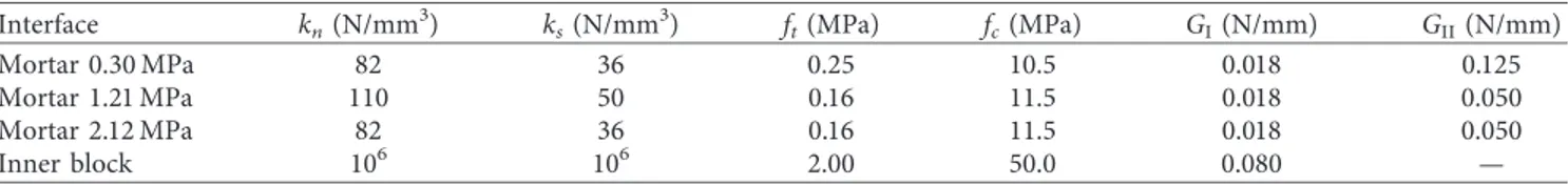
The main mechanical parameters adopted for mortar interfaces and inner block interfaces are listed in Table 1 and were determined by performing laboratory tests on blocks, mortar, and mortar joints. In particular, mortar interface stiffness parameters are obtained starting with a material having Em�800 MPa, Eb�4672 MPa, and ]m�0.14, and their nonlinear behavior in shear is characterized by co-hesion c � 1.4 ft and friction ratio μ � 0.75, whereas inner block interfaces nonlinear behavior is considered only for tensile and bending failure. The FE-TRSCM adopts E � 3960 MPa, ] � 0.14, fc�8.8 MPa, and GC�2 N/mm.
The numerical results obtained with the proposed re-fined rigid block model turn out to be in quite good agreement with experimental results. Focusing on the load-displacement curves (Figure 5), the initial stiffness of the panels is correctly reproduced by the numerical model in the three different compression cases. The level of initial failure of the panels is correctly determined with p � 1.21 MPa, whereas it is slightly underestimated with p � 0.30 MPa and overestimated with p � 2.12 MPa. The residual strength of the panels is correctly determined only with p � 0.30 MPa, probably thanks to the small level of compression of the case study.
Figure 6 shows the deformed configurations (left col-umn, Figures 6(a)–6(c)) and the interface damage (right column, Figures 6(d)–6(f )) obtained at d � 2 mm during the pushover tests for the three compression cases considered. Deformed configurations are characterized by the opening of vertical mortar joints (cyan color in Figures 6(d)–6(f )) and by the sliding of horizontal joints (red color in Figures 6(d)–6(f )) along the diagonal direction of the panel from panel top left corner to panel bottom right corner. Increasing the level of compression, the interface damage increases and involves also vertical inner block interfaces, which are mainly characterized by bending failure (yellow color in Figures 6(d)–6(f )). The deformed configurations reached at d � 2 mm with p � 1.21 and 2.12 MPa (Figures 6(b) and 6(c)) are similar, but a slightly large vertical deformation can be observed with 2.12 MPa. In these numerical simu-lations, the compressive strength of mortar joints is never reached; hence, the corresponding representation is not highlighted in the legend of Figure 6.
Figure 7 collects the deformed configurations and the tangential stresses obtained with the FE-TSRCM at d � 2 mm during the pushover tests where the damage along the di-agonal of the panel is more evident in the case with low compression level and less evident in the case of high compression level.
The comparison between the numerical results of the proposed refined rigid block model with respect to labo-ratory tests and numerical results obtained with FE-TSRCM shows that the behavior of mortar interfaces subjected to
compression has to be taken into account into the rigid model, given that the hypothesis of elastic behavior and unlimited strength in compression assumed in the rigid
model does not allow to correctly reproduce the softening branch of the pushover tests, together with the compressive failure of some mortar joints close to the top left and bottom Tension failure Shear failure
(a) (b)
(c) (d)
Figure 2: Tension (a, c) and shear (b, d) tests on two blocks specimens. Deformed configurations (a, b) and interface damage (c, d).
0.00 0.02 0.04 0.06 0.08 0.10 dn (mm) Tension 0.1MPa 0.5MPa 1.0MPa 0 0.1 0.2 0.3 0.4 0.5 0.6 0.7 Fn /A (MP a) (a) 0.00 0.20 0.40 0.60 0.80 1.00 ds (mm) Shear 0.1MPa 0.5MPa 1.0MPa 0 0.2 0.4 0.6 0.81 1.2 1.4 1.6 1.8 Fs /A (MP a) (b)
Figure 3: Load-relative displacement curves for a) tension test, b) shear tests with three levels of compression, on two blocks connected by a mortar joint.
H p
L F
Table 1: Mechanical properties of mortar joints and inner block joints of the case studies considered.
Interface kn(N/mm3) ks(N/mm3) ft(MPa) fc(MPa) GI(N/mm) GII(N/mm)
Mortar 0.30 MPa 82 36 0.25 10.5 0.018 0.125 Mortar 1.21 MPa 110 50 0.16 11.5 0.018 0.050 Mortar 2.12 MPa 82 36 0.16 11.5 0.018 0.050 Inner block 106 106 2.00 50.0 0.080 — p = 0.30 MPa 0 10 20 30 40 50 60 F (kN) 0.50 1.00 1.50 2.00 2.50 3.00 3.50 4.00 4.50 0.00 d (mm) (a) p = 1.21MPa 0 10 20 30 40 50 60 70 80 F (kN) 0.50 1.00 1.50 2.00 2.50 3.00 3.50 4.00 4.50 0.00 d (mm) (b) 0.00 0.50 1.00 1.50 2.00 2.50 3.00 3.50 4.00 4.50 d (mm) p = 2.12MPa 0 20 40 60 80 100 120 F (kN) (c)
Figure 5: Pushover curves of the numerical shear tests with varying compression. Continuous line for refined rigid block model, dotted line for FE-TSRCM, and dashed line for laboratory test results.
p = 0.30 MPa (a) p = 1.21 MPa (b) p = 2.12 MPa (c) Figure 6: Continued.
Tension failure Shear failure Bending failure p = 0.30 MPa (d) Tension failure Shear failure Bending failure p = 1.21 MPa (e) Tension failure Shear failure Bending failure p = 2.12 MPa (f )
Figure 6: Deformed configurations (a, b, and c) and interface damage (d, e, and f ); continuous lines, mortar interfaces and dashed lines, inner block interfaces) at d � 2 mm of the numerical shear tests with varying compression.
p = 0.30MPa τ12 (MPa) 4.0 –1.0 (a) p = 1.21MPa τ12 (MPa) 3.3 –1.1 (b) p = 2.12MPa τ12 (MPa) 2.6 –1.5 (c)
right corner of the panels. However, even if load-displace-ment curves obtained with the FE-TSRCM are very close to the actual behavior of the panels, the deformed configura-tions are not able to highlight the local damage of mortar joints or blocks.
A further comparison between the results given by the proposed refined rigid block model with respect to the original one is briefly described in appendix in terms of load-displacement curves. For further details on the results given by the standard rigid block model, the recent contribution by authors [49] can be taken into consideration.
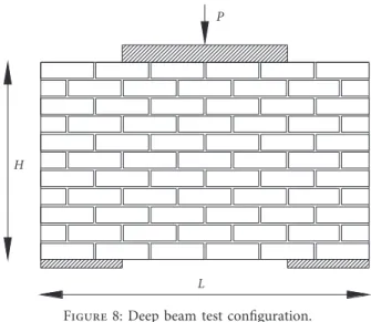
3.4. Masonry Deep Beam Subjected to a Vertical Force. In order to further evaluate the proposed refined rigid block model, the “Page test” [29] is simulated. Such test is one of the most used in the calibration of numerical models for
masonry panels [1, 37, 57], and it was used by authors for an initial calibration of the original nonlinear discrete/rigid block model [17]. The specimen is made of pressed clay blocks having dimensions b = 122 mm, a = 34 mm, and s = 37 mm, with mortar joint thickness e = 5 mm; overall panel dimensions are L = 757 mm and H = 457 mm. The panel is supported at each side of the base, and it is loaded by a compressive symmetric force P applied by a stiff steel beam long 381 mm. Load and restraint conditions are shown in Figure 8. Brick and mortar linear and nonlinear mechanical parameters are presented in Table 2 where several data are taken from the work of Lourenço [1]. The FE-TRSCM adopts E = 4125 MPa, ] = 0.15, fc= 13 MPa, and GC= 1 N/mm.
Figure 9 shows the load-displacement curve obtained with the rigid block and continuous numerical models. The refined rigid block model reaches an ultimate force close to 122.2 kN that turns out to be in quite good agreement with
P
L H
Figure 8: Deep beam test configuration.
Table 2: Mechanical properties of mortar joints and inner block joints of the masonry deep beam test.
Interface kn(N/mm3) ks(N/mm3) ft(MPa) fc(MPa) GI(N/mm) GII(N/mm)
Mortar 165 70 0.29 8.60 0.018 0.050 Inner block 106 106 2.00 50.0 0.080 — 0 20 40 60 80 100 120 140 P (kN) 0.20 0.40 0.60 0.80 1.00 0.00 d (mm)
Figure 9: Pushover curves of the numerical masonry deep beam tests. Continuous line for refined rigid block model, dotted line for FE-TSRCM, and dashed line for laboratory test results.
Figure 10: Deformed configuration close to the end of the nu-merical deep beam tests (P � 100 kN).
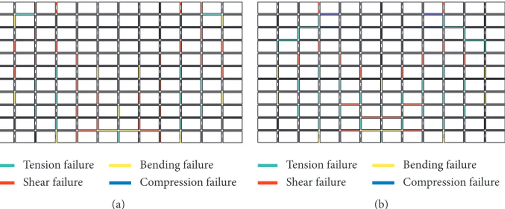
Tension failure Shear failure Bending failure Compression failure (a) Tension failure Shear failure Bending failure Compression failure (b)
Figure 11: Interface damage close to the end of the numerical deep beam test: (a) P � 100 kN; (b) P � 120 kN. Continuous lines, mortar interfaces; dashed lines, inner block interfaces.
σ22 (MPa)
0.4
–11.7
Figure 12: Deformed configuration and vertical normal stresses at P � 100 kN load level performed with the FE-TSRCM.
p = 0.30MPa 0 10 20 30 40 50 60 F (kN) 0.50 1.00 1.50 2.00 2.50 3.00 3.50 4.00 0.00 d (mm) (a) p = 1.21MPa 0 10 20 30 40 50 60 70 80 90 100 F (kN) 0.50 1.00 1.50 2.00 2.50 3.00 0.00 d (mm) (b) p = 2.12MPa 0.00 0.50 1.00 1.50 2.00 2.50 3.00 d (mm) 0 20 40 60 80 100 120 140 F (kN) (c)
Figure 13: Pushover curves of the numerical shear tests with varying compression. Continuous line for refined rigid block model, dotted line for original rigid block model, and dashed line for laboratory test results.
experimental result equal to 109.2 kN, whereas the FE-TSRCM is in excellent agreement with such results, since it reaches an ultimate force close to 108.2 kN. In this case, the continuous model shows a larger deformability with respect to the rigid one, and the pushover curves are characterized by the same initial stiffness up to 20 kN; then the FE-TSRCM starts to exhibit damage in compression, which causes a stiffness reduction of the model.
Figures 10 and 11(a) show, respectively, the deformed configuration of the deep beam and the damage map at P � 100 kN, which correspond to the last load increment considered by Page. The deformed shape of the panel is in agreement with the one proposed by Lourenço [1], and the damage of the panel is characterized by the shear, bending, and tension failure of several vertical joints, in quite good agreement with the numerical results of Page [29] and Lourenço [1]. Figure 11(b) shows the damage map at P � 120 kN, which is characterized by the compression failure of several bed joints (blue color) and the shear failure of two inner block joints (red color, dashed line) close to the upper steel beam, together with the further tension and shear failure of some vertical mortar joints.
Figure 12 shows the deformed configuration and the map of normal stresses in y2direction obtained with the
FE-TSRCM at P � 100 kN. The deformed configuration is in quite good agreement with that obtained with the rigid model, even if the continuous model shows a more diffused deformability along the entire specimen. The map of normal stresses clearly shows the load transfer from the upper steel beam and the lower supports.
4. Conclusions
In this work, a refined rigid block model has been proposed for studying the in-plane behavior of masonry with regular texture. The refined rigid block model is based on an existing model with rigid blocks and elastoplastic interfaces that already demonstrated its effectiveness in representing masonry be-havior in linear and nonlinear fields, and it was compared with other commercial DE models and laboratory results. However, the original elastic-perfectly plastic law adopted for restraining interface actions of dry or mortar joints was not sufficiently in agreement with actual material behavior; moreover, the model was not able to represent the possible block cracking. For these reasons, the proposed model improves the original one by assuming rigid quadrilateral elements connected by one-di-mensional nonlinear interfaces, which are adopted both to represent mortar (or dry) joints between the blocks and also to represent inner potential cracks into the blocks. Furthermore, the softening behavior of interfaces in tension and shear is taken into account. The computational effort required for performing numerical tests with the updated rigid block model is still smaller than that typical of commercial DE and FE models, since the degrees of freedom of the rigid block model are lumped at block centers.
Several numerical tests are performed for first by sim-ulating the tension and shear cracking of two blocks con-nected by a mortar joints and then by considering masonry panels with regular texture subjected to compression and shear. Particular attention is given to the collapse mecha-nisms and the pushover curves obtained numerically and compared with existing numerical and laboratory results. The numerical simulation of the three shear tests with different compression levels originally performed by Raij-makers and Vermeltfoort [50] turned out to be in quite good agreement with the laboratory test and other numerical results obtained with a FE-TRSCM approach. Furthermore, the numerical simulation of the deep beam test originally performed by Page [29] showed a good agreement with laboratory results both in terms of ultimate load and crack pattern.
Further developments of this work will focus on a more accurate simulation of the behavior of joints in compression, by taking into account, for instance, of the softening be-havior typical of the compressed mortar joints, in order to better reproduce the postpeak branch of the pushover tests. The proposed rigid block model will be further validated and calibrated by simulating other laboratory tests and more complex case studies, such as masonry walls and façades with openings.
Appendix
The refined rigid block model proposed in this work can be used as the original one by simply avoiding the deform-ability and potential damage of the inner block interfaces. However, the original rigid block model is characterized by a smaller number of degrees of freedom involved in the numerical tests, namely one half of the overall number of degrees of freedom, with respect to the refined rigid block model. A comparison between the load-displacement curves and the damage maps obtained with the refined and standard rigid block models is showed in the following figure by performing the first three pushover tests con-sidered in Section 3.3.
As it has already been highlighted in the introduction and in Section 2.2, the original rigid block model is not able to reproduce the softening behavior typical of mortar joints in tension and shear; hence, the original rigid block model is not able to represent a possible reduction of shear capacity after the damage has occurred on the masonry panel. This aspect is less evident in the shear test with the lower compression level (Figure 13(a)), where also the refined rigid block model is not able to correctly represent the larger shear resistance of the panel and the subsequent softening and residual resistance. The difference between the refined and standard rigid block model is more evident in the other two cases with a larger level of compression on the panels (Figures 13(b) and 13(c)).
Data Availability
The data used to support this study are available from the corresponding authors upon request.
Conflicts of Interest
The authors declare that there are no conflicts of interest regarding the publication of this paper.
Acknowledgments
This work was financed by the Research Project PRIN 2017 (grant 2017HFPKZY_002), project “Modelling of constitu-tive laws for traditional and innovaconstitu-tive building materials.”
References
[1] P. B. Lourenço, “Computational strategies for masonry structures,” Ph.D. thesis, Delft University, Delft, Netherlands, 1996.
[2] P. Roca, M. Cervera, G. Gariup, and L. Pel`a, “Structural analysis of masonry historical constructions. classical and advanced approaches,” Archives of Computational Methods in Engineering, vol. 17, no. 3, pp. 299–325, 2010.
[3] H. Smoljanovic, N. Zivaljic, and Z. Nikolic, “Overview of the methods for the modelling of historical masonry structures,” Gradevinar, vol. 65, no. 7, pp. 603–618, 2013.
[4] P. A. Cundall, “A computer model for simulating progressive large scale movements in blocky rock systems,” in Proceedings of the Symposium of International Society of Rock Mechanics, Nancy, France, 1971.
[5] P. A. Cundall and R. D. Hart, “Development of generalized 2-d an2-d 3-2-d 2-distinct element programs for mo2-deling jointe2-d rock,” Final report, ITASCA Consulting Group, Minneapolis, MN, USA, 1985.
[6] P. A. Cundall and R. D. Hart, “Numerical modelling of discontinua,” Engineering Computations, vol. 9, no. 2, pp. 101–113, 1992.
[7] J. V. Lemos, “Discrete element modeling of masonry struc-tures,” International Journal of Architectural Heritage, vol. 1, no. 2, pp. 190–213, 2007.
[8] P. B. Lourenço and J. G. Rots, “Multisurface interface model for analysis of masonry structures,” Journal of Engineering Mechanics, vol. 123, no. 7, pp. 660–668, 1997.
[9] A. M. D’Altri, S. de Miranda, G. Castellazzi, and V. Sarhosis, “A 3D detailed micro-model for the in-plane and out-of-plane numerical analysis of masonry panels,” Computers & Struc-tures, vol. 206, pp. 18–30, 2018.
[10] L. Macorini and B. A. Izzuddin, “A non-linear interface el-ement for 3D mesoscale analysis of brick-masonry struc-tures,” International Journal for Numerical Methods in Engineering, vol. 85, no. 12, pp. 1584–1608, 2011.
[11] E. Minga, L. Macorini, and B. A. Izzuddin, “A 3D mesoscale damage-plasticity approach for masonry structures under cyclic loading,” Meccanica, vol. 53, no. 7, pp. 1591–1611, 2018. [12] F. Cannizzaro, B. Pant`o, S. Caddemi, and I. Cali`o, “A Discrete Macro-Element Method (DMEM) for the nonlinear structural assessment of masonry arches,” Engineering Structures, vol. 168, pp. 243–256, 2018.
[13] M. Pepe, M. Sangirardi, E. Reccia, M. Pingaro, P. Trovalusci, and G. de Felice, “Discrete and continuous approaches for the failure analysis of masonry structures subjected to
settlements,” Frontiers in Built Environment, vol. 6, no. 43, pp. 1–14, 2020.
[14] M. Pepe, M. Pingaro, P. Trovalusci, E. Reccia, and L. Leonetti, “Micromodels for the in-plane failure analysis of masonry walls: limit analysis, FEM and FEM/DEM approaches,” Frattura Ed Integrita Strutturale, vol. 14, no. 51, pp. 504–516, 2020.
[15] E. Reccia, L. Leonetti, P. Trovalusci, and A. Cecchi, “A multiscale/multidomain model for the failure analysis of masonry walls: a validation with a combined FEM/DEM approach,” International Journal for Multiscale Computa-tional Engineering, vol. 16, no. 4, pp. 325–343, 2018. [16] A. Cecchi and K. Sab, “A comparison between a 3D discrete
model and two homogenised plate models for periodic elastic brickwork,” International Journal of Solids and Structures, vol. 41, no. 9-10, pp. 2259–2276, 2004.
[17] D. Baraldi and A. Cecchi, “Discrete approaches for the nonlinear analysis of in plane loaded masonry walls: mo-lecular dynamic and static algorithm solutions,” European Journal of Mechanics—A/Solids, vol. 57, pp. 165–177, 2016. [18] R. K. Livesley, “Limit analysis of structures formed from rigid
blocks,” International Journal for Numerical Methods in Engineering, vol. 12, no. 12, pp. 1853–1871, 1978.
[19] C. Baggio and P. Trovalusci, “Limit analysis for no-tension and frictional three-dimensional discrete systems,” Mechanics of Structures and Machines, vol. 26, no. 3, pp. 287–304, 1998. [20] M. C. Ferris and F. Tin-Loi, “Limit analysis of frictional block assemblies as a mathematical program with complementarity constraints,” International Journal of Mechanical Sciences, vol. 43, no. 1, pp. 209–224, 2001.
[21] M. Gilbert, C. Casapulla, and H. M. Ahmed, “Limit analysis of masonry block structures with non-associative frictional joints using linear programming,” Computers & Structures, vol. 83, no. 13-14, pp. 873–887, 2006.
[22] F. Portioli, C. Casapulla, L. Cascini, M. D’Aniello, and R. Landolfo, “Limit analysis by linear programming of 3D masonry structures with associative friction laws and torsion interaction effects,” Archive of Applied Mechanics, vol. 83, no. 10, pp. 1415–1438, 2013.
[23] D. Baraldi, E. Reccia, A. Cazzani, and A. Cecchi, “Compar-ative analysis of numerical discrete and finite element models: the case of in-plane loaded periodic brickwork,” Composites: Mechanics, Computations, Applications, An International Journal, vol. 4, no. 4, pp. 319–344, 2013.
[24] D. Baraldi, E. Reccia, and A. Cecchi, “DEM & FEM/DEM models for laterally loaded masonry walls,” in Proceedings of the 5th ECCOMAS Thematic Conference on Computational Methods in Structural Dynamics and Earthquake Engineer-ing—COMPDYN 2015, pp. 2144–2157, Crete Island, Greece, 2015.
[25] D. Baraldi, E. Reccia, and A. Cecchi, “In plane loaded masonry walls: DEM and FEM/DEM models. A critical review,” Meccanica, vol. 53, no. 7, pp. 1613–1628, 2018.
[26] A. Munjiza, The Finite/Discrete Element Method, John Wiley & Sons, Chicester, UK, 2004.
[27] F. Portioli, L. Cascini, C. Casapulla, and M. D’Aniello, “Limit analysis of masonry walls by rigid block modelling with cracking units and cohesive joints using linear programming,” Engineering Structures, vol. 57, pp. 232–247, 2013.
[28] P. B. Lourenço, J. G. Rots, and J. Blaauwendraad, “Two ap-proaches for the analysis of masonry structures: micro and macro-modeling,” Heron, vol. 404 pages, 1995.
[29] A. W. Page, “Finite element model for masonry,” Journal of the Structural Division, vol. 104, pp. 1267–1285, 1978.
[30] P. De Buhan and G. de Felice, “A homogenization approach to the ultimate strength of brick masonry,” Journal of the Me-chanics and Physics of Solids, vol. 45, no. 7, pp. 1085–1104, 1997.
[31] R. Luciano and E. Sacco, “Homogenization technique and damage model for old masonry material,” International Journal of Solids and Structures, vol. 34, no. 24, pp. 3191–3208, 1997.
[32] G. Milani, “Simple homogenization model for the non-linear analysis of in-plane loaded masonry walls,” Computers & Structures, vol. 89, no. 17-18, pp. 1586–1601, 2011.
[33] E. Bertolesi, G. Milani, and P. B. Lourenço, “Implementation and validation of a total displacement non-linear homoge-nization approach for in-plane loaded masonry,” Computers & Structures, vol. 176, pp. 13–33, 2016.
[34] D. Addessi and E. Sacco, “A multi-scale enriched model for the analysis of masonry panels,” International Journal of Solids and Structures, vol. 49, no. 6, pp. 865–880, 2012.
[35] I. Stefanou, J. Sulem, and I. Vardoulakis, “Three-dimensional Cosserat homogenization of masonry structures: elasticity,” Acta Geotechnica, vol. 3, no. 1, pp. 71–83, 2008.
[36] G. Salerno and G. De Felice, “Continuum modeling of pe-riodic brickwork,” International Journal of Solids and Struc-tures, vol. 46, no. 5, pp. 1251–1267, 2009.
[37] M. L. De Bellis and D. Addessi, “A cosserat based multi-scale model for masonry structures,” International Journal for Multiscale Computational Engineering, vol. 9, no. 5, pp. 543–563, 2011.
[38] A. Bacigalupo and L. Gambarotta, “Non-local computational homogenization of periodic masonry,” International Journal for Multiscale Computational Engineering, vol. 9, no. 5, pp. 565–578, 2011.
[39] D. Baraldi and A. Cecchi, “Discrete element model for in-plane loaded viscoelastic masonry,” International Journal for Multiscale Computational Engineering, vol. 12, no. 2, pp. 155–175, 2014.
[40] F. da Porto, G. Guidi, E. Garbin, and C. Modena, “In-plane behavior of clay masonry walls: experimental testing and fi-nite-element modeling,” Journal of Structural Engineering, vol. 136, no. 11, pp. 1379–1392, 2010.
[41] B. Ghiassi, D. V. Oliveira, P. B. Lourenço, and G. Marcari, “Numerical study of the role of mortar joints in the bond behavior of FRP-strengthened masonry,” Composites Part B: Engineering, vol. 46, pp. 21–30, 2013.
[42] V. Gattulli, G. Lampis, G. Marcari, and A. Paolone, “Simu-lations of FRP reinforcement in masonry panels and appli-cation to a historic facade,” Engineering Structures, vol. 75, pp. 604–618, 2014.
[43] X. Wang, B. Ghiassi, D. V. Oliveira, and C. C. Lam, “Mod-elling the nonlinear behaviour of masonry walls strengthened with textile reinforced mortars,” Engineering Structures, vol. 134, pp. 11–24, 2017.
[44] V. G. Haach, G. Vasconcelos, and P. B. Lourenço, “Study of the behaviour of reinforced masonry wallets subjected to diagonal compression through numerical modelling,” in Proceedings of the 9th International Masonry Conference, Guimaraes, Portugal, 2014.
[45] L. Miccoli, D. V. Oliveira, R. A. Silva, U. M¨uller, and L. Schueremans, “Static behaviour of rammed earth: exper-imental testing and finite element modelling,” Materials and Structures, vol. 48, no. 10, pp. 3443–3456, 2015.
[46] C. B. de Carvalho Bello, A. Cecchi, E. Meroi, and D. V. Oliveira, “Experimental and numerical investigations on the behaviour of masonry walls reinforced with an innovative
sisal FRCM system,” Key Engineering Materials, vol. 747, pp. 190–195, 2017.
[47] C. B. de Carvalho Bello, G. Boscato, E. Meroi, and A. Cecchi, “Non-linear continuous model for three leaf masonry walls,” Construction and Building Materials, vol. 244, p. 118356, 2020. [48] G. Bartoli, M. Betti, P. Biagini et al., “Epistemic uncertainties in structural modeling: a blind benchmark for seismic as-sessment of slender masonry towers,” Journal of Performance of Constructed Facilities, vol. 31, no. 5, Article ID 04017067, 2017.
[49] D. Baraldi, C. B. de Carvalho Bello, A. Cecchi, E. Meroi, and E. Reccia, “Nonlinear behavior of masonry walls: FE, DE, and FE/DE models,” Composites: Mechanics, Computations, Ap-plications: An International Journal, vol. 10, no. 3, pp. 253– 272, 2019.
[50] T. M. Raijmakers and A. T. Vermeltfoort, “Deformation Controlled meso shear tests on masonry piers,” Report B-92-1156, TNO-BOUW/TU Eindhoven, Build. and Constr. Res., Eindhoven, Netherlands, 1992.
[51] M. Petracca, L. Pel`a, R. Rossi, S. Zaghi, G. Camata, and E. Spacone, “Micro-scale continuous and discrete numerical models for nonlinear analysis of masonry shear walls,” Construction and Building Materials, vol. 149, pp. 296–314, 2017.
[52] J. G. Rots and J. Blaauwendraad, “Crack models for concrete: discrete or smeared, fixed, multi-directional or rotating,” Heron, vol. 34, no. 1, pp. 1–59, 1989.
[53] J. G. Rots, “Computational modeling of concrete fracture,” Ph.D. thesis, Delft University of Technology, Delft, Nether-lands, 1988.
[54] TNO DIANA, DIsplacement Method ANAlyser, Release 9.4, User’s Manual, https://dianafea.com/manuals/d94/Diana. html, 2010.
[55] R. van der Pluijm, “Material properties and its components under tension and shear,” in Proceedings of the 6th Canadian Masonry Symposium, Saskatoon, Canada, June 1992. [56] R. van der Pluijm, “Shear behaviour of bed joints,” in
Pro-ceedings of the 6th North American Masonry Conference, pp. 125–136, Philadelphia, PA, USA, 1993.
[57] J. Lopez, S. Oller, E. Oñate, and J. Lubliner, “A homogeneous constitutive model for masonry,” International Journal for Numerical Methods in Engineering, vol. 46, no. 10, pp. 1651– 1671, 1999.