Titolo
UPGRADE AND EXPERIMENTAL TESTS IN THE HLM
FACILITY NACIE-UP WITH A PROTOTYPICAL THERMAL
FLOW METER
Descrittori
Tipologia del documento: Rapporto Tecnico
Collocazione contrattuale: Accordo di programma ENEA-MSE su sicurezza nucleare e reattori di IV generazione
Argomenti trattati:
Generation IV reactors, Tecnologia dei metalli liquidi
Sommario
The present report is focused on the design and test of a prototypical thermal flow meter for liquid metals that will be installed into the NACIE-UP (NAtural CIrculation Experiment-UPgrade) facility located at the ENEA Brasimone Research Center (Italy).
The measurement techniques available in the market can measure the flow rate in heavy liquid metal but with the drawback of a relevant pressure drop. For relatively low flow rates (0-10 kg/s) and natural circulation loops is important to reduce the pressure drop in natural circulation conditions. Moreover the repeatability of the measure is often very relevant in the experiments. Therefore a new type of prototypical flow meter based on ‘thermal’ principle was developed at the ENEA Brasimone Research centre in collaboration with Thermocoax, who manufactured the device. A prototype was designed by ENEA, manufactured by Thermocoax and then tested at ENEA both in water and in HLM.
Note
Authors: I. Di Piazza, V. Sermenghi, G. Polazzi
Copia n. In carico a:I. Di Piazza
2 NOME
FIRMA
1 NOME
FIRMA
0 EMISSIONE 19/09/2016 NOME I.Di Piazza A. Del Nevo M. Tarantino FIRMA
List of contents
1. INTRODUCTION ... 3
2. THE UPGRADE OF THE NACIE FACILITY (NACIE-UP): AN OVERVIEW ... 4
3. WORKING PRINCIPLE OF THE PROTOTYPICAL FLOW METER ... 12
4. TESTSINWATER ... 13
5. TESTSINHLM ... 14
6. CONCLUSIONS ... 17
1. INTRODUCTION
The present report is focused on the design and test of a prototypical thermal flow meter for liquid metals that will be installed into the NACIE-UP (NAtural CIrculation Experiment-UPgrade) facility located at the ENEA Brasimone Research Center (Italy).
The measurement techniques available in the market can measure the flow rate in heavy liquid metal but with the drawback of a relevant pressure drop. For relatively low flow rates (0-10 kg/s) and natural circulation loops is important to reduce the pressure drop in natural circulation conditions. Moreover the repeatability of the measure is often very relevant in the experiments. Therefore a new type of prototypical flow meter based on ‘thermal’ principle was developed at the ENEA Brasimone Research centre in collaboration with Thermocoax, who manufactured the device. A prototype was designed by ENEA, manufactured by Thermocoax and then tested at ENEA both in water and in HLM.
2. THE UPGRADE OF THE NACIE FACILITY (NACIE-UP): AN
OVERVIEW
NACIE-UP is a rectangular loop which allows to perform experimental campaigns in the field of the thermal-hydraulics, fluid-dynamics, chemistry control, corrosion protection and heat transfer and to obtain correlations essential for the design of nuclear power plant cooled by heavy liquid metals. It basically consists of two vertical pipes of O.D. 2.5 in. (63.5 mm)), working as riser and downcomer, connected by two horizontal pipes of O.D. 2.5 in. (63.5 mm)). The whole height of the facility is about 7.7 m, while the horizontal length is about 2.4 m. A section of the facility is devoted to place the prototypical fuel pin bundle simulator (FPS) test sections in the lower part of the riser. In the last experimental campaign (2015), a wire-wrapped 19-pin 250 kW FPS was mounted. The test section for the blockage experiment will be placed in place of the previous one. A proper heat exchanger is placed in the upper part of the downcomer.
NACIE-UP is made of stainless steel (AISI 304) and can use both lead and the eutectic alloy LBE as working fluid (about 2000 kg, 200 l of total capacity). It was designed to work up to 550°C and 10 bar. The difference in height between the center of the heating section and the center of the heat exchanger is about 5.5 m and it is very important for the amount of the natural circulation. In the riser, an argon gas injection device ensures a driving force to sustain forced convection in the loop.
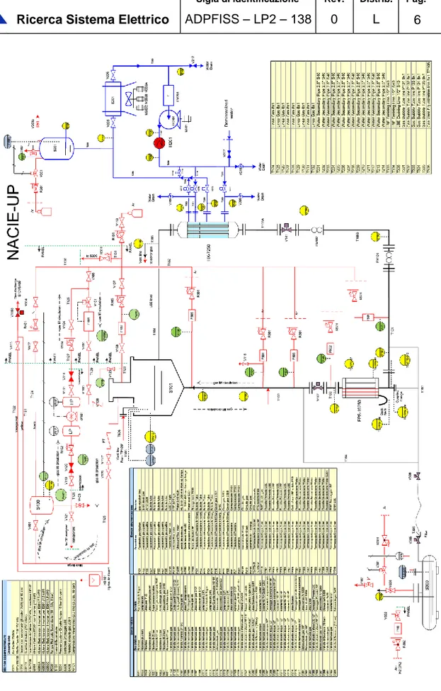
The P&ID of the facility is reported in Figure 1, while a schematic layout of the primary circuit is reported in Figure 2. The facility includes:
The Primary side filled with LBE, with 2.5 in. (63.5 mm) pipes. It consists of two vertical pipes, working as riser and downcomer, two horizontal pipes and an expansion tank;
A Fuel Pin Simulator (19-pins) 250 kW maximum power, placed in the bottom of the riser of the primary side (it will be replaced by the new BFPS test section);
A Shell and tube HX with two sections, operating at low power (5-50 kW) and high power (50-250 kW). It is placed in the higher part of the downcomer;
3 bubble tubes to measure the pressure drops across the main components and the pipes;
A differential pressure transducer (1 mbar accuracy) for the test section;
A prototypical thermal flow meter (ENEA/Thermocoax R&D) based on the heat transfer phenomena across the component;
Several bulk thermocouples to monitor the temperature along the flow path in the loop;
The Secondary side, filled with water at 16 bar, connected to the HX, shell side. It includes a pump, a pre-heater, an air-cooler, by-pass and isolation valves, and a pressurizer with cover gas;
An ancillary gas system, to ensure a proper cover gas in the expansion tank, and to provide gas-lift enhanced circulation;
A LBE draining section, with 0.5 in. (12.7 mm) pipes, isolation valves and a storage tank.
The ancillary gas system has the function to ensure the cover gas in the expansion tank and to manage the gas-lift system in the riser for enhanced circulation regime.
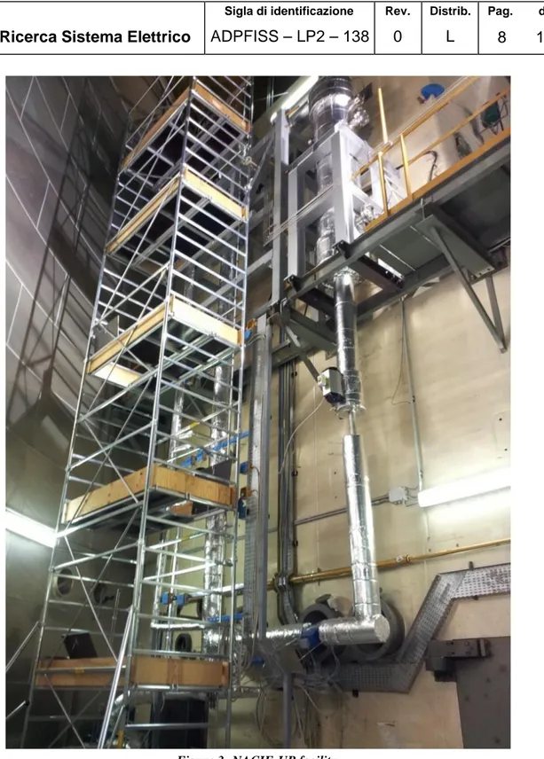
The primary system is ordinary filled with liquid LBE and it is made by several components, pipes and coupling flanges. Pipes T101, T102, T103, T104, T105 are austenitic SS AISI304 2.5ʺS40, I.D. 62.68 mm. Figure 3 shows a picture of the primary side of the NACIE-UP facility.
An expansion tank (S101) is located at the end of the riser and is partially filled with Argon as cover gas to control the pressure inside the primary circuit. Two level sensors LD101, LD102, are located respectively 80 and 180 mm above the outlet nozzle of the riser, inside the expansion vessel.
A drawing of the expansion vessel (S101) is reported in Figure 4. Pipe 1 in Figure 4 is welded to the pipe working as riser (T103) and ends with a nozzle 285 mm long inside the tank.
Figure 4: Layout of the expansion vessel inside the primary circuit of the NACIE-UP facility.
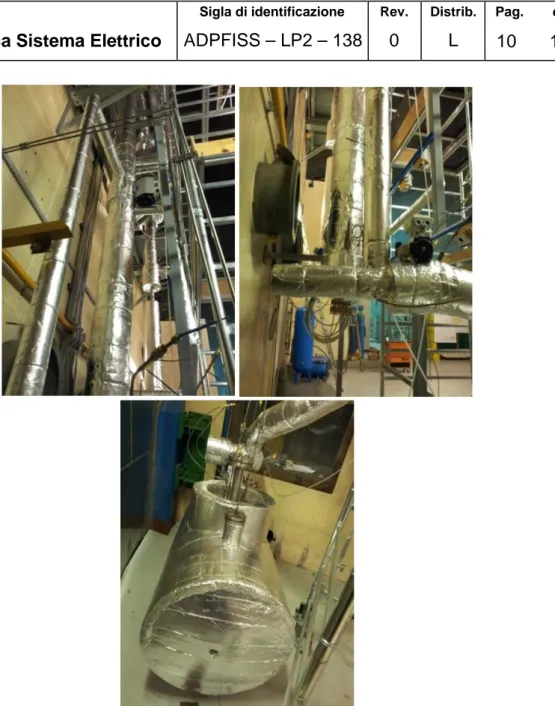
The fill and drain system has been designed to be completely controlled by DACS by proper fill and drain operational procedures. This system is made of austenitic SS AISI304 1/2ʺ pipes, isolation valves, a filter (T305) and a storage tank (S300). In Figure 5 some components of the fill and drain system are shown.
Figure 5: Sketches of the fill and drain system of the NACIE-UP facility.
In the riser, an argon gas injection device ensures a driving force to sustain enhanced circulation regime in the loop. The gas injection system is composed of a 9 mm I.D. pipe inserted inside the riser and is connected to the ancillary gas system. The pipe is 6135 mm long starting from the 2 ½” coupling flange in the upper part expansion tank and ends with a 4.35 mm I.D. hook-shaped pipe.
The secondary side is a 16 bar pressurized water loop, with a circulation pump PC201, a pre-heater H201, the HX shell side, an air-cooler E201 and a pressurizer S201. Components of the secondary side are depicted in Figure 6. The pressurizer is connected to the gas lines to ensure an Argon cover gas and to regulate the loop pressure though DACS. Most of the valves are motorized in order to ensure the full operability of the secondary loop by DACS. The valve system allows to drain and fill the two sections of the HX shell separately from the control room. A bypass of the HX is ensured by V214 for the pre-heating of the secondary water. The heating section H201 allows to heat-up the secondary fluid to have flexibility in managing low FPS powers. The ultrasonic flow meter FM201 allows to monitor
the secondary water mass flow rate, while several thermocouples will monitor temperature in the loop; the combination of the two information will allow to quantify the power exchange in the HX. The heat exchanger is shell and tube type and has been designed to exchange heat up to 250 kW. Two separated shell sections have been built: a counter-current high-power section (0-30 kW) and a cross-flow low power section (30-250 kW), both connected to the pressurized water secondary side. The two sections can be drained and filled separately.
Further details on the facility and the experimental activities connected can be found in (Di Piazza et al., 2016).
3. WORKING PRINCIPLE OF THE PROTOTYPICAL FLOW METER
The basic concept of the flow meter includes an heater and a static mixer.
The scheme is not tied to the real design and manufacturing of the flow meter but it is only representative of the concept. Two different RTD will measure inlet and outlet temperature of the HLM. An Heater will provide power to the fluid while a static mixer will ensure the perfect mixing.
Two different measurements techniques are adopted (two flow meters in one): 1. Energy balance (absolute) ‘Thermal method’
2. PID on bulb heater to keep a constant bulb-fluid temperature difference (calibrated on the first measure in stationary condition) ‘3D method’
The second method ensures fast response to transient and independence by the inlet temperature.
Further details cannot be provided because the patent process must start in November 2016.
4. TESTS IN WATER
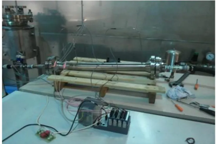
A first characterization was performed in water to asses methodologies and accuracy of the new instrument. Figure 8 shows the experimental set-up used to perform the tests. An independent vortex flow meter was put in line in order to compare flow rates.
The aim of the water tests were to elaborate and implement the ‘3D’ hot bulb technique. This was made in two different steps:
• Calibration curves (Power, mass flow rate) were taken at different inlet temperatures;
• The ‘3D’ hot bulb techniques was implemented; .
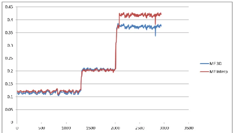
An example of calibration curve in water is shown in Figure 9, while a comparison between thermal and ‘3D’ value is shown in Figure 9.
Figure 7 Flow meter and test rig used for the experimental tests in water.
Figure 9 Example of comparison between thermal and 3D value.
It must be underlined that the full develop of the ‘3D’ techniques was not straightforward and required several months of different tries and optimizations. Further details of the technique cannot be provided here because of the patent process to be started.
5. TESTS IN HLM
After water tests, fundamental tests were carried out by mounting the flow meter in the HLM facility NACIE-UP (described in Section 2). The tests aimed to assess the repeatability of the thermal method and to optimize and use the ‘3D’ method in a real HLM flow.
Both goals were reached.
In order to separate the effects of inlet temperature and flow rate, the facility was operated with the secondary loop empty by varying the argon injection flow rate at constant loop temperature. Figure 11 and Figure 11 shows the tests, in terms of Ar-injection and Thermal mass flow rate, at 300 °C and 400 °C. The tests showed also clearly a great repeatability of the thermal measure in the same experimental conditions.
The accuracy of the thermal method cannot be assessed directly by experimental tests, but it is based on fundamental principle and an error analysis based on propagation theory can be carried out. This analysis was carried out but it is not presented here for patent pending reasons. From the analysis a maximum error of 3%, mainly due to the uncertainty on the thermo-physical properties, was computed.
Therefore a characterization of the NACIE-UP loop was carried out by thermal flow meter measurements. This is shown in Table 1 where the LBE mass flow rate [kg/s] is reported by varying temperature and Argon injection flow rate. The main parameter influencing the flow is the gas-injection flow rate, but there is an effect from the temperature due to the variability of viscosity with temperature. In particular, for a given Argon flow rate, the LBE flow rate increases with temperature because the viscosity will decrease. The maximum flow rate in the facility with gas lift is 5 kg/s about. During experiments with the FPS, the value can be overtaken for the buoyant force acting in the loop.
Figure 10 Experimental test of the Thermal flow meter in the HLM facility NACIE-UP at 300 °C.
Figure 11 Experimental test of the Thermal flow meter in the HLM facility NACIE-UP at 400 °C. 0 1000 2000 3000 4000 5000 6000 0 0.5 1 1.5 2 2.5 3 3.5 4 4.5 5 Time [s] L B E M a s s f lo w [ k g /s ] TLBE = 400 °C 0 1000 2000 3000 4000 5000 60000 2 4 6 8 10 12 14 16 18 20 A r M a s s f lo w [ N l/ m in ] MFR-th Ar
Table 1 Mass flow characterization [kg/s] at different temperatures and gas flow rate in the NACIE-UP facility.
6. CONCLUSIONS
The present paper is focused on the design and test of a prototypical thermal flow meter for liquid metals that will be installed into the NACIE-UP (NAtural CIrculation Experiment-UPgrade) facility located at the ENEA Brasimone Research Center (Italy).
The measurement techniques available in the market can measure the flow rate in heavy liquid metal but with the drawback of a relevant pressure drop. For relatively low flow rates (0-10 kg/s) and natural circulation loops is important to reduce the pressure drop in natural circulation conditions. Therefore a new type of prototypical flow meter based on ‘thermal’ principle was developed at the ENEA Brasimone Research centre in collaboration with Thermocoax, who manufactured the device. A prototype was designed by ENEA, manufactured by Thermocoax and then tested at ENEA both in water and in HLM.
The thermal flow meter with ‘thermal balance’ showed very good features in stability and repeatability. The accuracy of the flow meter was computed as less than 3% by error propagation analysis.
These are the main conclusions:
• The thermal balance showed great repeatability and stability in all conditions both in water and HLM;
• The PID ‘hot-bulb’ 3D methodology was developed and calibrated on the thermal balance in stationary conditions, and it has a good response in any condition also for transients;
• The ‘thermal balance’ method coupled with the PID gives also a good response to transient;
• Accuracy is good with a maximum error below 3%, computed by error analysis; • The instrument can be used both for thermal-hydraulic and for corrosion loops
where the repeatability and stability of the measure is important; • The pressure drop is very low, much less of the rest of the loop; • Possible collaboration to test it in CEA or at Thermocoax with sodium;
7. REFERENCES
I. Di Piazza, M. Angelucci, R. Marinari, M. Tarantino, N. Forgione, “Heat Transfer On Hlm
Cooled Wire-Spaced Fuel Pin Bundle Simulator In The Nacie-Up Facility”, Nucl. Eng.