Table Of Contents
List of Figures ... 3
List of Tables ... 4
List of Acronyms ... 5
Executive Summary ... 6
1. Introduction and scope ... 7
2. Passive containment cooling system operation and description (AP1000-like configuration) ... 9
3. Reliability assessment of passive containment cooling system (AP1000-like configuration) ... 12
3.1. Failure analysis ... 12
3.2. Fault tree failure probability ... 15
4. Interface with T-H analysis ... 18
5. Conclusions of the reliability analysis ... 20
6. Study of a new in-vessel corium retention strategy ... 22
6.1. Background and Introduction ... 22
6.2. IVR approach ... 24
7. Molten Pool Behaviour and Structural Integrity of RV ... 27
7.1. Analysis approach: assumption and modelling ... 28
7.1.1. Core accident progression ... 28
7.1.2. Boundary conditions of core melt ... 29
7.2. Thermal analysis ... 31
7.3. Thermal analysis: FEM analysis ... 33
8. Pool behaviour analyses: results’ discussion ... 37
8.1. Analytical results ... 37
8.2. Numerical results ... 39
9. Final summary ... 48
List of Figures
Figure 1: AP1000 Passive containment cooling system ... 10
Figure 2: Flow chart of passive containment cooling system in AP1000 ... 11
Figure 3: Functional failure fault tree of PCCS system ... 13
Figure 4: Fault tree for PCCS ... 16
Figure 5: Schematic IVMR phenomenology [9] and heat transfer processes in the melt progression. ... 23
Figure 6: Heat flux vs. RV angular position of lower head in IVR ... 24
Figure 7: Schematic in-vessel melt progression sequence ... 25
Figure 8: Scheme of the internal core catcher (dashed surface at the vessel lower head on the left figure) and of the SiC-SiC structure with alumina pebble boxes (right figure). ... 26
Figure 9: Scheme of the melt pool. Temperatures Tw, Tm and Tl or Tb refer the water, the molten core, the light metal layer and to the crust, respectively. ... 30
Figure 10: Represantation of the core debris relocated at the lower head, in a steady-state condition, and made of either solid oxidic crust and/or melt oxidic pool (left figure). Analytical model of core debris with outer RV insulator (instead of adiabatic boundary condition) [20], on the right figure. For this latter boundary conditions are T(R1)=Tcorium and T(R5)=Twater. The thermal insulation (layer C) is assumed 0.25 m thickness (0.15 W/m/K of thermal conductivity) as the real one in nuclear reactor [16-17]. ... 32
Figure 11: Hypothetical representation of steel and Al2O3 contacting surface. ... 32
Figure 12: Strength and Young modulus behaviour vs temperature for the alumina ... 35
Figure 13: FEM model of the vessel lower head ... 35
Figure 14: Temperature trend for IVR with and without ICC solution. ... 38
Figure 15: Radial temperature in the bottom head for T(R4) = 100°C. ... 38
Figure 16: Circumferential stress behaviour, in the A, B and C layers, as function of the corium temperature ... 39
Figure 17: Contour plot of temperature in the alumina and steel wall (a) in the case of external water cooling. In particular, the temperature distribution through the vessel wall is give in (b). ... 41
Figure 18: Contour plot of temperature in the alumina and steel wall in the case of absence of external water-cooling. ... 41
Figure 20: Contour plot of temperature in the bottom head wall for 0.5m of relocated corium (a). In the figure (b) the distribution of temperature in the steel wall of vessel is also shown 43 Figure 21: Results of thermo-mechanical analysis: temperature (a) and stress (b) in the bottom head thickness (outward direction according to the arrow versus) in the case external water-cooling and full melt core relocation. In the Figure 20 (b) zooming of temperature trend in the alumina and steel thickness is given. ... 44 Figure 22: Stress distribution in the bottom head wall in the case external water cooling (a) and full melt core relocation. In the bottom figure (b) is given the countur plot in steel thickness. ... 45 Figure 23: Stress trend in the bottom head thickness in the case external water cooling and full melt core relocation. ... 46 Figure 24: Temperature (a) and stress (b) distribution in the bottom head of vessel, for 0.1m alumina thickness, in the case of external water cooling and full melt core relocation. ... 47
List of Tables
Table 1: Failure probabilities for the PCCS ... 14 Table 2: Geometrical and material properties used in the model [17-19] ... 32 Table 3: Material properties for FEM simulation ... 34
List of Acronyms
AP 600/1000 Advanced Passive
CCF Common Cause Failure
CET Containment Event Tree CMC Ceramic Matrix Carbide
DW Drywell
ENEA Italian National Agency for New Technologies, Energy and Sustainable Economic Development
ESBWR Economic Simplified Boiling Water Reactor EVR Ex-Vessel melt Retention
FAPCS Fuel and Auxiliary Pools Cooling System FMEA Failure Mode and Effect Analysis
GDCS Gravity Driven Cooling System
HEX Heat Exchanger
IAEA International Atomic Energy Agency
IC Isolation Condenser
ICC Internal Core Catcher ICS Isolation Condenser System IVR In-Vessel Retention
IVCR In-Vessel Corium Retention IVMR In Vessel Melt Retention LOCA Loss of Coolant Accidents LWR Light Water Reactor
MC Monte Carlo
MFCI Molten Fuel-Coolant Interaction
MELCOR Methods for Estimation of Leakages and COnsequences of Releases MSLB Main Steam Line Break
NCF Natural Circulation Failure NPP Nuclear Power Plant PCC Passive Cooling Condenser
PCCS Passive Containment Cooling System PCF PCC Condenser Failure
PCCWST Passive Containment Cooling Water Storage Tank
PSA Probabilistic Safety Assessment, Probabilistic Safety Analysis PWR Pressurized Water Reactor
RMPS Reliability Methods for Passive Systems RPV Reactor Pressure Vessel
R-S Resistance - Stress
SAM Severe Accident Management SBWR Simplified Boiling Water Reactor SMA Safety Margin Assessment
SSC Structure System and Components
T-H Thermal-hydraulic
Executive Summary
The Fukushima incident highlighted, among other aspects, the need for the implementation of strategies for the management of severe accidents (SAM, Severe Accident Management), in the form of engineering safeguards aimed at minimizing the risk of radioactive substances leakage and likewise increase the level of protection of the plants.
In this regard, therefore, the objective of the international scientific community is to identify the engineering measures capable of increasing the capacity of the structure in the face of the updated demand, deriving from this type of severe events.
In light of the innovative reactor designs (such as AP1000) an activity is therefore proposed aimed at assessing the robustness of the various systems of protection of the plant, aimed at mitigating the consequences of severe accidents, such as, for example, for the disposal of heat from the Containment (PCCS, Passive Containment Cooling System), for the purpose of maintaining the function of confinement and containment of radioactive products, and to avoid the interaction of Corium with concrete (IVMR, In-Vessel Melt Retention). Specific systems are analyzed in terms both probabilistic (reliability) and deterministic (resistant capacity). For the proposed purposes, we will use preliminary analytical and / or numerical simplified models that will allow us to study the complexity of the incidental transient and highlight the benefits deriving from the implementation of the strategies for managing the severe incidents proposed; the same applies to assessments of newly developed safety safeguards in terms of performance and relative effectiveness.
The activity is intended as a completion and finalization of the two previous years, refer to ENEA report ADP-FISS-LP1-072 “Analysis relating to the implementation of the sfaety safeguards for the severe accident management in nuclear reactors”, issued in September 2016, which shows the design implementation through some specific passive concepts and ENEA report ADPFISS-LP1-096 “Assessment of the safeguards to cope with the consequences of severe accidents in nuclear power plants”, delivered in November 2017, where the safety and reliability assessemnt of any of the proposed systems is offered.
1. Introduction and scope
The extensive use of passive safety systems, designed to extend the coping period in the event of adverse situations such as occurred at the Fukushima Daiichi plant, is one of the most relevant strategy envisaged to meet the requirements to enhance the safety of nuclear power plants through increased safety system reliability, as devised in [1], which provides a list of systems, consistent with the available knowledge as emerging, for the most, from a literature survey.
IAEA-TECDOC-626 provides definitions for safety related terms as applied to advanced reactors [2].
The study deals with the assessment of passive systems, implemented in reactor designs to exercise and ensure the safety functions such as removing heat from the containment and the control and abatement of the amount of hydrogen that could break free, following a severe accident involving the melting of the core. As for this latter, the corium coolability (i.e., preventing melt-through of physical barriers) is recognized as the “Achilles-heel” of the Gen. II or earlier PWR designs such that to cope with this issue solutions adopted by Gen. III reactors consider the adoption of in-vessel melt retention (IVR) or ex-vessel melt retention (EVR) solution.
It has to remark also that the state of knowledge with respect to PWR in-vessel core-melt progression has not changed substantially from TMI-2. It is thought that a melt pool forms in the original core volume and then progress downwards into the lower plenum, to commence the thermal loading on the lower head. The new information is on the effects of accident-management actions, e.g., water addition to a hot core. This may increase the damage and the hydrogen generation, due to the Zircalloy oxidation.
The initial attack of the melt on the lower head is in the form of a jet, whose composition may well be fully oxidic.
Deeper consideration of these processes could provide a better understanding on how to assess and increase the thermal margin related to the in-vessel melt retention.
In particular, considering the specificities of their operation, a careful analysis is required to evaluate the vessel performance and ascertain the accomplishment of the required safety mission. Within a risk informed approach, the study proposes:
• on the one hand, the assessment of the reliability of passive systems, conceived to maintain the function of containment of radioactive products, as a follow-on of [1], which shows some specific aspects of passive systems for further evaluation of safety in a reliability plane.
• on the other hand it is intended to study the behavior of the containment structures, such as the vessel, the containment system, etc., in order to assess from a deterministic point of view the safety margin (SMA) and propose engineering solutions/safeguards, based as well on the use of innovative materials for in-vessel retention, aimed at mitigating the effects of a severe accident scenarios.
To these aims, we will employ analytical and/or simplified numerical models, which allow to study the complexity of the transitional incidental and highlight the benefits of implementing the proposed strategies for the management of severe accidents.
2. Passive containment cooling system operation and description
(AP1000-like configuration)
The passive containment cooling system in AP1000 [3] is a safety-related system that functions to reduce containment temperature and pressure following a loss-of-coolant accident (LOCA) accident, a main steam line break (MSLB) accident inside containment, or other events that cause a significant increase in containment pressure and temperature.
The function of the AP1000 passive containment cooling system (PCCS) is to prevent the containment vessel from overheating and exceeding the design pressure, which could result in a breach of the containment and the loss of the final barrier to radioactive release.
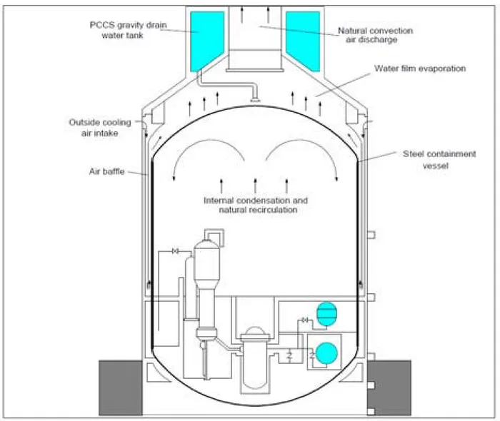
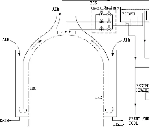
The PCCS consists of the following components (Figure 1):
• Air inlet and exhaust paths that are incorporated in the shield building structure • An air baffle that is located between the steel containment vessel and the concrete
shield building
• A Passive Containment Cooling (PCCWST) Water Storage Tank that is incorporated in the shield building structure above the containment
• A water distribution system.
In particular the passive containment cooling system water storage tank outlet pipe is equipped with three sets of redundant isolation valves. In two sets, air-operated butterfly valves are normally closed and open upon receipt of actuation signals. The third parallel supply line contains a normally closed motor-operated valve. And each valve fails open on loss of power or loss of air. In addition to these normally closed valves, there is a normally open motor operated valve in each of the three lines.
The PCCS is required to effectively cool the containment following an accident such that the design pressure is not exceeded and the pressure is rapidly reduced. The steel containment vessel itself provides the heat transfer surface that allows heat to be removed from inside the containment and rejected to the atmosphere. Heat is removed from the containment vessel by a natural circulation flow of air through the annulus formed by the outer shield building and the steel containment vessel it houses.
Outside air is pulled in through openings near the top of the shield building and pulled down, around the baffle and then flows upward out of the shield building.
The flow of air is driven by the chimney effect of air heated by the containment vessel rising and finally exhausting up through the central opening in the shield building roof.
Figure 1: AP1000 Passive containment cooling system
If needed, the air cooling can be supplemented by water evaporation on the outside of the containment shell. The water is drained by gravity from a tank located on top of the containment shield building.
Three normally closed, fail-open valves will open automatically to initiate the water flow if a high containment-pressure threshold is reached. The water flows from the top, outside, domed surface of the steel containment shell and down the side walls allowing heat to be transferred
and removed from the containment by evaporation. The water tank has sufficient capacity for three days of operation, after which time the tank could be refilled, most likely from the ancillary water storage tank. The flow chart of the system illustrated in Figure 1 is shown in Figure 2.
3. Reliability assessment of passive containment cooling system
(AP1000-like configuration)
Alike the ESBWR case [4], AP1000 Passive Containment Cooling system assessment “appears” to be not very critical from the reliability viewpoint, since, as assessed in [1], the system operation doesn’t pose any relevant risk with respect to the expected performance. To date in the open literature there are not studies focusing specifically on the reliability of the system, rather the available studies investigate the related efficiency/performance, that is the heat removal capacity of PCCS of advanced passive PWR during severe accidents.
Results show that the heat removal capacity of PCCS, during severe accident scenarios, can keep the containment pressure below the acceptance criterion for a range of severe accident challenges and the AP1000 containment is likely to remain intact and to not be bypassed: as a result, the plant has a significantly reduced frequency of release of large amounts of radioactivity following core damage [1]. Conversely, in this study the performance assessment in reliability terms is dealt with. In fact, since the system operation is based on natural circulation and air is the cold source, so physical process failure becomes one of the important failure modes, which should be considered in system failure prognosis.
3.1. Failure analysis
For the passive system reliability analysis, the success criterion adopted is Pcontainment < design value: here, P containment is the total pressure in the containment, and design value is the critical parameter if P containment exceeds such value it is considered that the containment will lose its function, in our case P < 0.4MPa [3].
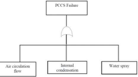
Actually the passive containment cooling systems introduced in AP600/AP1000 design are based upon heat exchange process of steam condensation/evaporation between the steel containment and the heat sink (i.e., atmosphere) and include condensation of steam in containment atmosphere, air convection, thermal conduction. The “functional” fault tree depicted in Figure 3, includes the likely failure modes impairing the PCCS system operation.
Figure 3: Functional failure fault tree of PCCS system
The preliminary qualitative safety analysis in [1] doesn’t reveal relevant risk factors impairing the system performance such that the safety function is challenged, due to the fact that the corresponding probabilities of the modes of failure are very low if not negligible.
The underlying considerations are the following.
Both air circulation and internal condensation processes don’t need any external activation and it is quite unlikely that their operation can be compromised by t-h factors which may reduce the heat exchange process like surface oxidation and cracking or decrease the rate of natural circulation like the envelope failure and fouling.
Finally as far as the water spray function is concerned, the level of redundancy and diversification (like the three redundant and diverse drain valves) contribute to improve the rank of safety and reliability of the system. However, the necessity for the quantification of the system reliability is recognized, in order to endorse and add credit to the outcome of the qualitative analysis.
As in the previous case, [4], the quantitative procedure involves the evaluation of the components needed for assuring the passive operation of the system.
The system failure can be induced by equipment default and physical process failure, and part of the equipment failing may increase the failure probability of the physical process.
Three main failure modes are identified to be the loss of air flow, the loss of natural circulation within the containment and the failure of the water supplemental system.
Loss of air flow is due to obstruction of the air ingress/outlet and is modelled by a component, like “strainer”, plugging.
For the system described in previous section, the air inlets are composed of three rows of air inlet holes, one or two rows failure may result in the decreasing of heat transfer capability as assessed in [5], which deals with the aspect related to the effect of air temperature on the failure prediction of the containment cooling system, by means of code simulations: again, as in previous case, due to the limited resources, this aspect is not addressed, while acknowledging its relevance.
We’ll assume the failure of the function upon two of the three rows of air inlet failure, independently of the external air temperature. Internal condensation and natural recirculation process is not estimated to be subject to failure by itself, since it is conditional upon cooling the external containment.
Finally the water spray supply system is evaluated in terms of train valves failures.
The reliability data for natural circulation failure modes are once again from [6] and [7] upon engineering judgment, as reported in Table 1, together with the corresponding failure probabilities. Failure probabilities are assessed taking a 72 hours value for the mission time Tm of the system consistently with the passive system requirement.
Note that single component failure probabilities are evaluated in the form of λ*Tm , which is acceptable for λ* Tm <0.1 like in the present case. Note that loss of primary boundary is not accounted, since it is judged incredible.
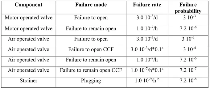
Table 1: Failure probabilities for the PCCS
Component Failure mode Failure rate Failure
probability
Motor operated valve Failure to open 3.0 10-3/d 3 10-3 Motor operated valve Failure to remain open 1.0 10-7/h 7.2 10-6 Air operated valve Failure to open 3.0 10-3/d 3 10-3 Air operated valve Failure to open CCF 3.0 10-3/d*0.1a 3 10-4 Air operated valve Failure to remain open 1.0 10-7/h 7.2 10-6 Air operated valve Failure to remain open CCF 1.0 10-7/h*0.1a 7.2 10-7
Strainer Plugging 1.0 10-9/h b 7.2 10-8
a: beta factor for CCF b: engineering judgement
3.2. Fault tree failure probability
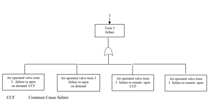
In this paragraph the failure probability of the system is evaluated adopting the approach based on classical fault tree, which is constructed in Figure 4.
2/3
PCCS failure
Air inlet
failure Water supply failure
Air inlet row
failure 1 Air inlet row failure 2
Train 2 and 3 failure Train 1
failure
Motor operated valve failure to open on demand Motor operated valve failure to remain open on demand Train 2
failure Train 3 failure
Air operated valve train 2 failure to open
on demand Air operated valve train
2 failure to open on demand CCF Air operated valve train
2 failure to remain open Air operated valve train
2 failure to remain open CCF
Air inlet row failure 3
CCF Common Cause failure
Figure 4: Fault tree for PCCS
The construction of the fault tree under discussion differs from the previous one, represented in Figure 2, in that the branch directly addressing the “natural circulation” and the relative modes of failure is not contemplated, as illustrated in the previous paragraph. Moreover, if, in case of ESBWR PCCS, all the events are linked by OR gates [2], making the assessment quite straightforward, this case presents, in addition, AND gates as well as a 2 out of 3 event.
The two out of three event for the air inlet occurs if two or three of the identical components fail and is calculated by means of the binomial distribution, so that:
P (two components fail) = 3P2(1-P) P (three components fail) = P3
Where P is the individual probability of failure, with P= 0.7*10-7
Adding the probabilities of these mutually exclusive events in which the system will fail gives:
P= 3P2(1-P) + P3
This sum gives a negligible failure probability value of the oreder of 10-10.
The events in the tree are denoted as follows, as regards the water supply water unavailability: Air operated valve train
3 failure to open on demand CCF
Air operated valve train 3 failure to open
on demand
Air operated valve train 3 failure to remain open
CCF
Air operated valve train 3 failure to remain open Train 3
failure
WSF Water supply failure
A motorized operated valve failure to open on demand B motorized operated valve failure to remain open C air operated valve failure to open on demand train 2 D air operated valve failure to remain open train 2 E air operated valve failure to open on demand CCF F air operated valve failure to remain open CCF G air operated valve failure to open on demand train 3 H air operated valve failure to remain open train 3 WSF = (A+B) * (C*G+C*H+D*G+D*H+E+F) WSF=A*C*G+A*C*H+A*D*G+A*D*H+A*(E+F)+B*C*G+B*C*H+B*D*G+B*D*H+B*( E+F) WSF= 2.7 10-8 +6.4 10-11 +6.4 10-11 +1.5 10-13 + 9 10-7 + 6.4 10-11 + 1.5 10-13 + 1.5 10-13 + 3.4 10-16 + 2.1 10-9
Results from this reliability study present very low values for the probability of failure of the system under investigation, of the order of 10-6, due to the CCFs, thus confirming the outcome of [1], which didn’t reveal any relevant risk factors for the system to accomplish the safety function.
The study shows AP1000 PCCS reliability figure is affected mainly by the supplemental water system availability and in particular the Common Cause Failures of the train valves, whose occurrence decreases the system reliability.
4. Interface with T-H analysis
The connection of MELCOR simulations to reliability assessment and probabilistic safety assessment (PSA) provides both an opportunity and a challenge. In fact, it has to be noticed, that the simulations by the MELCOR code, do not relate directly to the reliability assessment of PCCS and the results are more useful to illustrate PCCS operation and performance. However, the information is valuable among other things for the determination of failure criteria for further reliability analysis and builds up the understanding of the phenomena involved.
For instance, quite obvious candidates for a failure criterion are the Containment pressure and temperature.
The reasons of this statement lies in the fact that MELCOR is intended primarily to model the progression of severe accidents. It is quite simple, approachable and flexible through its block based nature, but it may not be very effective in conducting analysis of performance or reliability for a single safety system such as PCCS. If intention is to obtain a numeric reliability estimate for PCCS, some more specific thermal-hydraulic codes could potentially be more practical for this purpose of use.
With MELCOR it is difficult to introduce probabilistic aspects into the analysis. It would be beneficial to conduct reliability assessment with a tool with which it is possible to sample system parameter values from given distributions, once the appropriate ones are determined. However, information gained via simulations can be exploited e.g. for determination of failure criteria. The simulation information can also be used in a dynamic approach to CET modelling, thus linking up with level 2 PSA. The result of the CET is then a probability distribution for the source term (consequence) of the CET.
If the objective of the analysis is to obtain a reliability estimate for PCCS, the reliability assessment would probably be more profitable with some other, more specific simulation tool, able to deal more effectively with some factors affecting PCCS function, like, for instance parameters such as pipe inclination and surface oxidation.
Obviously also the deterministic nature of the code poses some challenges, for probabilistic purposes. Maybe the most practical approach to simulation based reliability analysis would be to give system parameters some distributions from which to sample the values for them. The failure criteria would have been determined beforehand. This kind of Monte Carlo method
would require quite many simulation runs and the system reliability estimate would be determined according to the fraction of runs which do not exceed the chosen failure criteria. This is quite prohibitive to be performed with MELCOR, but as pointed out above, the MELCOR simulations can be advantageous for example in determination of reasonable failure criteria and in dynamic approach to CET modelling.
In the specific case of AP1000 PCCS, since the system operation is based on natural circulation and air is the cold source, so physical process failure becomes one of the important failure modes, which should be considered in system failure prognosis, and air temperature has important effect on system failure probability.
Monte Carlo (MC) simulation might be used to evaluate the system physical failure probability based on air temperature probability distribution, the effect of air temperature probability distribution on failure modes and the results of pressure distribution in the containment based on air temperature as illustrated in [5].
5. Conclusions of the reliability analysis
Natural circulation failure evaluation is included in the present study proposed for advanced LWR PCCS reliability assessment: this is attained through an approach aimed at the thermal-hydraulic performance assessment on the probability standpoint.
According to the previous section, some relevant methodologies for passive system reliability assessment, prompted so far, suggest propagation of important system uncertainties through Monte-Carlo simulation of a detailed best estimate mechanistic system, like MELCOR.
The main drawback consists in the requirement of a large number of system analyses using best estimate system code. Typically mechanistic thermal hydraulic codes of complex nuclear safety systems are computationally expensive and MC simulations using such models require considerable and often prohibitive computational effort to achieve acceptable accuracy. Consequently the issues pertaining to the natural circulation unavailability estimation suggest to approach the problem at the component level (see fault tree, figure 4), overlooking the failure modes related to the onset of thermal-hydraulic phenomena that would impair the passive function of the system, which appear to be negligible.
Consequently, as previously underlined, the outcome of the analysis represents a preliminary appraisal of the unavailability of a thermal-hydraulic passive systems for advanced GenIII+ reactors.
Qualitative analysis and fault tree construction are performed for safety-related systems that contribute to prevention or mitigation of severe accident events. The analysis identifies the importance of each component for each system.
Under the assumptions taken in the study results show a quite low value for the probability of failure, of the order of 10-6 .
The AP1000 design provides a passive means of maintaining the containment integrity by removing decay heat from the containment with water on the containment shell or through air cooling. This cooling ability reduces the potential of containment failure due to over pressurization after severe accident.
In particular, the diversity requirements adopted for the valves of passive containment cooling water storage tank minimize the consequences of Common Mode Failures to cause a loss of containment cooling.
The passive containment cooling system represents passive systems with thermal-hydraulic properties and therefore poses further challenges. The path forward includes the development of proper methods for reliability analysis of such systems becomes more urgent. If this study on PCCS reliability should be regarded as a preliminary analysis, it, however, lays the basis for further analysis to conduct the assessment with suitable tools, by leveraging the thermal-hydraulic simulations, and to yield any possible reliability estimate.
The features of suitable codes have to be examined in order to evaluate their appropriateness to effectively handle the issue for the given purpose.
6. Study of a new in-vessel corium retention strategy
6.1. Background and Introduction
Assuring the integrity of each NPP physical barriers becomes the corner stone of the defense-in-depth approach which is extensively employed in nuclear safety against the release of radioactivity to the environment. The understanding of severe accident (SA) phenomena and how to treat the phenomena evolving during SA are of meaningful importance to identify and propose (new) safety-oriented mitigation and/or retrofit measures.
The problem to deal with the safety systems, designed based on the “defense in depth” hierarchy, is to guarantee the design performance in the case of core damage (of frequency range 10-4 to 10-6/reactor-year). For this reason a better understanding of core degradation phenomena, of interaction with the coolant of the behaviour of melt in contact with the primary circuit and its cooling potential is of meaningful importance.
As indicated in the ADPFISS-LP1-096, during a severe accident, the occurrence of reactor core meltdown may cause the failure of the first physical barriers, leading possibly to exothermic reactions (in absence of coolability) with ablation and metal attacck of the reactor vessel lower head and to the release of a certain fraction of fission products to the pressure-bearing containment.
The corium coolability (i.e., preventing melt-through of physical barriers) has been in fact recognized as the “Achilles-heel” of the existing reactor designs. Therefore adequate performance (integrity and leak-tightness) of the containment in the aftermath of a postulated severe accident, thus, is of vital concern to avoid life-threatening event from the point of view of public safety.
The solutions proposed and adopted by Gen. III reactors are: in-vessel melt retention (IVR) or ex-vessel melt retention (EVR). They basically envisage the SA termination in the RPV or in the containment, respectively. The key strategy of IVR is to arrest and confine the corium in the lower head of the RPV by flooding the reactor pit (cavity), while EVR collects and cools the corium ejected from the RPV in a core catcher placed in the containment (like for the EPR and VVER).
The IVR strategy is considered the most effective measure to prevent the failure of the vessel bottom head, and of the containment and/or basemat melt-through, later. Consequently R&D
efforts spent in maximizing the safety this solution is able to assure (Figure 5) [8-9] should focus on the following open issues:
- vessel wall ablation due to the impingement of a melt jet, - melt coolability in the presence of water,
- in-vessel melt retention process in the presence of crust, - external cooling of the reactor vessel,
- critical heat flux (CFH) during external cooling, - lower head melting or creep-rupture process, and - vessel-hole ablation process.
Additionally, the following threats that these phenomena may pose to the containment integrity have to be investigated:
- Direct containment heating (re-hydration effects for Tcont > 90°C); - H2 combustion or steam explosion;
- Containment long term over-pressurization, bypass and leakage; and - Basemat melt penetration.
Figure 5: Schematic IVMR phenomenology [9] and heat transfer processes in the melt progression.
6.2. IVR approach
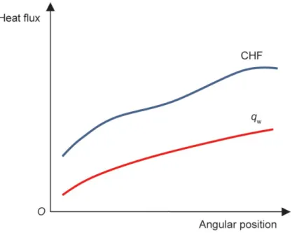
Conceptually the IVR approach benefits of external water cooling (flow normally driven by natural circulation) as it allows to remove the decay heat of the core melt relocated onto the reactor lower head [10÷13]. This solution is known as In-Vessel Corium Retantion (IVCR). By keeping the vessel wall cool the creep failure is prevented: this means to not exceed the limit of the external cooling capacity (or CHF) of boiling at all points around the vessel lower head (Figure 6). This latter emerged also in the analysis of the Fukushima accident: wider the CHF margin longer the time to manage plant emergency. On the contrary RPV melt-through may occur if water cooling/injection is not enough or unavailable for a prolonged period of time.
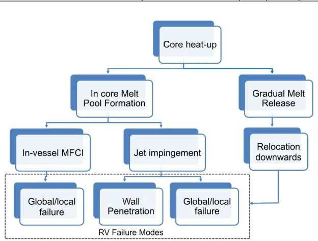
Figure 7 shows the most important phases (phenomena and possible interactions) of the in-vessel melt progression (IVMP) and the “expected” in-vessel failure modes that are typical for most existing/under deployment LWRs, which serve as a basis and rationale for identifying safety improvement. In this framework is inserted the CHF-reduction oriented solution that will be herein following investigated from a thermo-mechanical point of view.
Figure 7: Schematic in-vessel melt progression sequence
The solution proposed to improve the safety and support the SAM consists of an internal core catcher (ICC), developed at the DICI- University of Pisa, made of a SiC-SiC matrix inside which are inserted boxes with pebble ceramic material (i.e. alumina).
Figure 8 shows a scheme of the proposed device. It is a passive component to install inside the lower head; this make it less prone to mulfuncioning (“safety oriented solution”).
The material chosen as well as the geometrical configuration (‘thermal criterion’) make the ICC an innovative engineeristic system that could help in the SAM.
The internal and external liners of core catcher are made of high alloy steel.
The boxes instead are filled of alumina (Al2O3) in forms of pebbles. Al2O3 is chosen because of its high refractoriness, favorable thermal properties and capability to accommodate thermal expansion without high thermal stresses. This latter is strictly dependent on the thermal properties and may affect also packing factor of the boxes and as a result the thermal stresses.
Core heat-up In core Melt Pool Formation In-vessel MFCI Global/local failure Jet impingement Wall
Penetration Global/local failure
Gradual Melt Release
Relocation downwards
Figure 8: Scheme of the internal core catcher (dashed surface at the vessel lower head on the left figure) and of the SiC-SiC structure with alumina pebble boxes (right figure).
The way ICC will operate is theoretically simple: the alumina layer will not only increase the thickness of the bottom head of the RV but also will retard the core heat-up by acting as “thermal resistance” (in reason of its thermal conductivity lowering with the increase of temperature [13]). Accordingly, the thermo-chemical attack of the lower head, caused by the gradual decay-heated core melt (corium) relocation and/or inpingment downwards, is minimized or prevented (key benefit in SAM).
7. Molten Pool Behaviour and Structural Integrity of RV
Although the idea of ICC sounds quite simple, it is necessary to prove it with high confidence. In doing that the challenging task is determining precisely either the heat flux or the CHF, and especially the heat flux (qw) of the melt pool convection which is largely affected by in-vessel severe accident phenomena and accident scenarios. Due to the uncertainties in the understanding of the physical phenomena and accident scenarios, a deterministic approach is introduced and used, and conservative scenario is taken into consideration. Therefore to assess (theoretically and numerically) the feasibility of the proposed ICC, the starting point is the analysis of the the most important phenomena affecting the core heat-up [14÷18].
To remark is that core heat-up condition is instaured once the water level inside the reactor vessel drops, and, as widely known, the fuel clad temperature rises rapidly due to the decay heat in the fuel. After that the fuel heat-up accelerates beyond about 1500 K, when the Zr-H2O reaction is violent and the rate of heat generation may be much much greater than that of the decay heat. Reached the melting point, the molten material starts to relocate to the lower head of the RPV in form of oxidic or metallic jet.
“Being in contact with colder solid structures, the melt may solidify again, forming a barrier for the molten material coming later ("candling" and "blockage" processes”) [9].
In such a scenario, it has been recognized that vessel wall ablation (melting) due to jet impingement heat transfer could be a vessel failure mode, which has to be evaluated for assessment of the resulting containment loadings [11-12]. In addition, it emerged from the past 15 years of research on the IVMR that melt pool, if formed, may subsequently separate into 2 layers (i.e. lower oxidic layer and upper liquid metal layer) or 3 layers (heavy metal, oxidic and light metal layers), each of which is responsible of complex phenomena, suc as the global and local creep rupture, the focusing effects of metallic layer, the ablation of thw wall with water ingression or gap coling, molten fuel-coolant interaction (MFCI), etc.
Furtermore as indicated in [9], the in-vessel MFCI may cuase destructive energetic in-vessel steam explosions ('α-mode'), that is a soource of potential threat for vessel and containment integrity, and fragmentation of the core melt jet (‘debris’ behaviour).
Additionally, another concerns may be posed by the superheated metallic melt layer and by the freezing temperatures of both the metallic melt and the vessel wall (carbon steel) that are
close to each other (the large driving temperature difference for sidewall heat removal may result in vessel wall meltthrough).
Based on that it is possible to observe that the ICC issues to face are mostly affected by the heat-up of vessel wall and the heat removal capacity.
In general, the vessel heat-up will result in a reduction of mechanical strength of the vessel material; as a consequence, the lower head wall can be subjected to significant thermal and pressure loadings, and the lower head could fail due to creep rupture. In consideration of that, benefits the propsed ICC are clear, since a thin layer of it will serve as a thermal insulation, preventing the vessel wall from melting, and increasing the safety margin of plant.
Finally in the proposed study, the gap colling or the effects due to the resulting water ingression are not taken into account.
7.1. Analysis approach: assumption and modelling 7.1.1. Core accident progression
Briefly the degraded core accident progression that lead to core damage is dependent on large number of phenomena that can be extended over long periods of time. However, some common chemical and physical phenomena may be identified in their progression.
[14] identifies the following four time intervals, each of which is characterized by an own dominant phenomena:
(a) Initiation of accident until superheat in core;
(b) Superheat in core until core temperature exceeds 1500 K;
(c) Core temperature exceeding 1500 K until corium slumping (more likely to occur in PWRs than in BWRs, as learned from TMI-2 accident); and
(d) Formation of molten pool in lower plenum until vessel failure.
Phase (a) is very short, less than 10 min in case of LB-LOCA, or very long ranging from about 6 to 10 h in case of long-term LOSP or TMLB.
The phenomena in (a) are accompanied by a variation of pressure varies. After the core is uncovered - phase (b) -, heat transfer from the fuel to the steam is low compared with decay heat, and the fuel temperature increases till to clad ballooning and rupture (oxidation of Zircalloy and H2 generation).
Temperature may reach 1500 K for low-pressure sequences and 1700 K for high pressure sequences.
As clearly indicated in [14], at low pressure the stainless steel clad fails before reaching its melting point due to internal pressure, deformation, and contact/interaction effects. In BWRs, VVERs and some PWRs with boron carbide (B4C) as absorber, the major low-temperature reaction may occur at about 1500 K [16-17-18].
Phase (c) results in other core degradation phenomena; the reduced natural circulation between the core and the upper plenum may cause reduced heat transfer and hence a rapid heat-up of the core. In general, the core slumping or relocation into the lower plenum has to be described deterministically for all possible kinds of scenario and by abopting conservative assumptions regarding melt superheat, relocation rate, melt fragmentation etc. because of the low understanding of the complex phenomena occurring during this long time phase.
Phase (d) deals with the long-term behaviour of the corium relocated in the lower plenum. It is important for the estimation of RPV failure and the consequences for the thermal loads to the containment. If sufficient water is available in the lower plenum and the corium mass limited as in TMI-2, it might protect the wall from thermal loads. Otherwise local/global wall failure may occur.
7.1.2. Boundary conditions of core melt
The proposed internal core catcher approach is based on the successful coolability of the core melt: considered temperature is higher than 2273.15K, since the solidification temperature of melt corium jet may range from 1700K (for metal jets) to 3000K (for oxidic jets) at the bottom head, allowing the stabilization of the severe accident.
In such a scenario, the vessel wall ablation due to the jet impingement heat transfer is not considered because of the results obtained from the RIT/NPS experiments.
They showed that the stagnation zone, where the corium may relocate, should not be affected by the turbolence, which is the major physical mechanism governing the physics of fluid flow and heat transfer in the impingement area under phase change conditions.
Moreover it was observed that the rapid progression of the melt front and the increased heat transfer due to the surface roughness are tricky phenomena more for thin jet than for thick jet, are the case under investigation. Consequently, to evaluate efficacy of the ICC, the physical
situation of interest is, at this first stage, that characterising the relocated melt corium upon a meltable solid wall, i.e. vessel steel plus the layer of alumina.
The instauration of heat transfer processes will ensure that at least the bottom layers of the RPV wall are not undergoing “heat flux focusing effects” [18-19].
Based on the data obtained from the AP-600 accident scenario evaluation (specifically provided from COPO (Kymalainen et al., 1994), UCLA (Asfia and Dhir, 1994) and the mini-ACOPO (Theofanous et al., 1995) experiments, it is possible to assume that the reactor layer would be quite thick and the focused heat flux at the vessel wall was lower than the critical heat flux at the vessel outer wall.
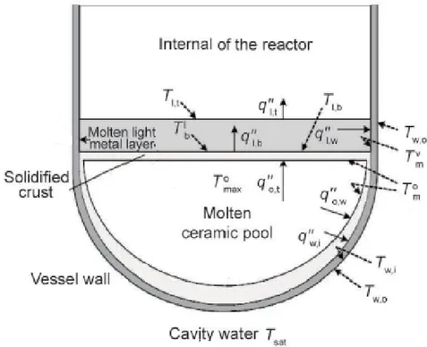
The metal layer resident on top of the oxidic pool (see the scheme of Figure 9) was found to focus the heat added to it from the oxidic pool towards. However, since in the analysis it is assumed that the core is entirely molten, the contribution of radiative heat transfer becomes lesser important than the contribution of conduction through the wall.
Figure 9: Scheme of the melt pool. Temperatures Tw, Tm and Tl or Tb refer the water, the molten core, the light metal layer and to the crust, respectively.
Summarising, the upward/downward splitting heat flux is affected by the stratification; indeed more heat is transfered downwards. Moreover, the heat flux towards the debris wall is
determined primarily by conduction and not by boundary layer flows, as for the unstably stratified regions.
The proposed ICC concept, by thickening the bottom head wall, may contribute to delay effects and consequences of the heat-up and, hence, avoid the “boiling crisis”.
7.2. Thermal analysis
The arrest of lower head heat-up and eventual quenching is the key to the survival of the RPV and for an appropriate SAM. To attain the aim it is needed to determine thermal loadings on acting on the lower head on the basis of the knowledge of progression of the core melt and degradation.
For the thermo-mechanical analyisis performed, homogeneous pool condition and stratified condition with an upper metallic layer and a lower oxide layer covering the RV wall are considered. In the analysed cases, very high temperature gradients occurred at the hemispherical boundary, the heat flux across this boundary reaching its maximum close to the upper pool surface.
The refence model for the calculation of the heat flow effects is shown in Figure 10, while the material properties are given in Table 2. Despite in reality the physical shape of relocated corium and of the melt RV internals are several; they may fall in the category of one-dimensional systems because of the identified boundary conditions, made assumptions and also because the temperature in the “body” is function of the radial distance (and is indipendent from the axial distance or azimuthal angle).
Figure 10: Represantation of the core debris relocated at the lower head, in a steady-state condition, and made of either solid oxidic crust and/or melt oxidic pool (left figure). Analytical model of core debris with outer RV insulator (instead of adiabatic boundary condition) [20], on the right figure. For this latter boundary conditions are T(R1)=Tcorium and
T(R5)=Twater. The thermal insulation (layer C) is assumed 0.25 m thickness (0.15 W/m/K of thermal conductivity) as the real one in nuclear reactor [16-17].
Table 2: Geometrical and material properties used in the model [17-19]
Component Radius [m] Thickness [m] Thermal conductivity [W/m/K] Core-catcher 2.50÷3.00 0.5 0.50 Vessel 3.00÷3.20 0.2 18.00 Insulator 3.20÷3.45/3.50 0.25/0.30 0.15 Water 3.45/3.50÷3.80 0.30/0.35 0.60
Another aspect to account for a proper description of the IVR heat processes is the thermal contact resistance, which arises along the junction formed by steel and Al2O3 (they have dissimilar thermal conductivity mainly) or contacting surface.
If a heat flux is imposed across it, the homogenenised (“uniform”) heat flow may be generally restricted to the conduction through the contact area, as shown in Figure 11.
Figure 11: Hypothetical representation of steel and Al2O3 contacting surface.
The presence of a solid medium between the contacting surfaces (with reference to Figure 10, corium-alumina, alumina-steel and steel-water sub-systems) may contribute to or restrict the
heat transfer, depending mostly upon the thermal conductivity, thickness, and hardness of the material. Since no gaps are expected between the contacting surfaces, any heat radiation is therefore prevented.
As for the energy balance across the corium-alumina-steel system, the heat contributions of the axial, azimuthal and time-dependent terms may be neglected.
Steady-state conditions is so assumed in the debris pool; the temperature is so represented by a continuous function that account for /equates heat generated and heat lost as well as the several and different materials thermal conductivities.
In this assessment the heat flux imposed at the lower head is assumed less than 1.5 MW/m2 (about 1.3 MW/m2 for 1000 MWe PWR, as confirmed by the ULPU-2000 experimental data); the thermal resistance along the upward thermal radiation path is maximized.
The set up model treats the case of a uniform composition, initially quenched, debris bed of zero porosity.
The hemispherical lower head wall is included in the modeling, its melt-through due to the thermal attack of the melt pool is calculated first analytically and numerically [20÷24].
The heat transport to the hemispherical boundary is through conduction, and, then, through a boundary layer created by the downward flow along the curved wall from the upper part of the pool: Fourier problem with direct integration solution.
No chemical reactions are considered for either the evaluation of proper thickness of pebble bed or temperature trend within the pool.
As for the latter, it was evaluated by assuming: (1) primary system depressurized; (2) lower head fully submerged in cavity water before that core debris reaches the lower head, and (3) water level in the cavity pit maintained indefinitely.
The lower head vessel integrity is calculated by considering several corium temperatures such to provide a wider overview of the core melt progression effects. The boundary conditions are consequently the core melt temperature and the water temperature (40 °C).
7.3. Thermal analysis: FEM analysis
Numerical analyses for analysing thermal performance of the ICC are performed by FEM code MSC©Marc. The preliminary model is implemented based on the scheme of relocation the core debris given in the previous Figure 10. In the modelling the presence of water in the
reactor lower plenum is not represented; this is a conservative assumption since the presence of gap cooling in the lower plenum vessel may be considered as a mechanism of keeping the vessel wall cool. The lower head wall is assumed subjected to thermal and pressure loads represented in terms of core melt temperature and pressure acting on the top surface.
For assessment of core meltdown accident progression, mode, timing and the possible vessel failure becomes of paramount importance [23÷27].
To the purpose of the thermo-mechanical simulation the following assumptions and restrictions are imposed:
• adiabatic condition on the core catcher external surface (no radiation flux surface) • no top surface cooling of corium cooled the by passive emergency cooling systems; • with and without insulator;
• isothermal boundary condition for the external vessel surface (T ~390K) cooling; • elasto-plastic behaviour for the vessel.
The initial conditions of 2000K for the oxidic debris and 1550K for the metallic layer become of minor importance because the thermal load to the vessel lower head is maximized when debris pool reaches a steady thermal state.
Additionally, Table 3 provides the specific material properties implemented as input for the simulation.
Figure 12 provides instead the trend of the stress and of the modulus of elasticty, respectively, as function of the temperature.
The alumina thermal conductivity trend is instead that obtained experimentally in [13].
Finally Figure 13 shows the set up and implemented FEM model used for the thermal safety margin assessment.
Table 3: Material properties for FEM simulation
Property Alumina Carbon Steel
Density 3970 kg/m3 7800 kg/m3
Specific heat 1560 J/kg K 514 J/kg K
Conductivity 10.5 W/mK 30 W/mK
Latent fusion heat 3577 kJ/kg
Yielding strength 3000 MPa 173 MPa
Figure 12: Strength and Young modulus behaviour vs temperature for the alumina
Figure 13: FEM model of the vessel lower head
The model is implementing element type 43, which is an eight-node, isoparametric, arbitrary hexahedral suitable for three-dimensional heat transfer applications. The conductivity of this
element is formed using eight-point Gaussian integration. The analyses performed have been the steaddy state and the thermal/mechanical transient. Direct integration method is used.
8. Pool behaviour analyses: results’ discussion
In this section we first briefly summarise results quoted in available literature, subsequently they are provided the stresses calculated with the reference model of previous Figure 10 right. FEM analyses results are also provided in what follows and critically discussed in terms of safety margin [28-29]. Moreover, based on the ultimate stress, the thermal endurance (γ) is calculated such to be able to measure the perfomance of the proposed core-catcher solution. It is obtained as:
γ =
σu α E�
k ρ cp�
1 2 (1)In Eq. (1) σu is the ultimate tensile stress, α is the thermal expansion coefficient, ρ is the density, k is thermal conductivity, and cp is the specific heat capacity.
8.1. Analytical results
It was highlighted that 20 cm of alumina results in about 12% reduction of the average vessel wall temperature: thicker this protective layer lower is the average vessel wall temperature. Moreover the parametric study performed to identify for which the temperature at R4 is less than 100 °C (t∞ condition) suggested that R5 be less than 0.15 m. In this case, the solution of Laplace equation is consistent with the problem and the steady-state solution can be used directly; no transient analysis is thus required.
Indeed, ICC reduces the heat-up from the lower head of vessel as shown in Figure 14: this positive effect immediately results in an increase of thermal safety margin.
Figure 14: Temperature trend for IVR with and without ICC solution.
Secondarily, Figure 15 shows the temperature behaviour calculated by ranging Tcorium from 1000 °C to 2000 °C for the worst heat transfer condition [20]. The circumferential stress are instead shown in Figure 16: thermal stresses are relevant inside the core-catcher and become negligible in the vessel wall. No stress state characterise the external vessel insulator.
Figure 15: Radial temperature in the bottom head for T(R4) = 100°C.
0 500 1000 1500 2000 2500 0 500 1000 1500 2000 2500 Vessel av er ag e t em per at ur e [° C] Corium temperature [°C] No core-catcher With core-catcher 0 400 800 1200 1600 2000 2,5 2,7 2,9 3,1 3,3 3,5 C ori um Te mp era tu re [° C] Radius r [m] T corium 1000°C T corium 1200 °C T corium 1400 °C T corium 1600 °C T corium 1800 °C T corium 2000 °C
Core-catcher Al2O3 Vessel
Figure 16: Circumferential stress behaviour, in the A, B and C layers, as function of the corium temperature
8.2. Numerical results
In general, the heat, transferred from the debris to the vessel wall, causes the lower head heat-up and in the long time may be reponsible of the weakening of the vessel strength.
This occurrs because of the degraded material properties caused by the high temperature. Figure 17 and Figure 18 show the distribution of the temperature as numerically calculated for thermal steady state condition.
They provide the temperature distribution in the assumed case of presence or absence of water external cooling. These contour plots clearly indicate the benefit of the allumina is delaying the heat transefer to the vessel wall also when the external cooling is exausting. In addition, by comparing the obtained results with the previous analytical results, it appear that results are in good agreement each others.
Without ICC, the heat conduction leads very soon to pre-heating of the solid vessel, due to the high conductivity of steel. When the removed heat flux is overwhelmed by the corium heat flux, the vessel ablation starts and in absence of external cooling increases slightly.
-2000 -1500 -1000 -500 0 500 1000 1500 2000 2,5 2,7 2,9 3,1 3,3 3,5 C ircu m fer en tial st ress [M Pa] Radius r [m] T corium 1000 °C T corium 1200 °C T corium 1400 °C T corium 1600 °C T corium 1800 °C T corium 2000 °C
Core-catcher Al2O3 Vessel
Figure 19 and Figure 20 show the behaviour of the temperature within the overall bottom head wall and in the steel vessel when the relocation of melt core are 1m and 0.5m respectively. The simulated case envisages the external water cooling.
After 1 hr from SA, it is possible to observe that the maximum value of the temperature is below the limit for which localized failure may appear. By analysing and comparing the showed temperature distributions it emerges clearly the positive role of the ceramic material in retarding the wall heating.
(b)
Figure 17: Contour plot of temperature in the alumina and steel wall (a) in the case of external water cooling. In particular, the temperature distribution through the vessel wall is give in (b).
Figure 18: Contour plot of temperature in the alumina and steel wall in the case of absence of external water-cooling.
Figure 19: Contour plot of temperature in vessel wall for 1m.
(b) Figure 20: Contour plot of temperature in the bottom head wall for 0.5m of relocated corium
(a). In the figure (b) the distribution of temperature in the steel wall of vessel is also shown
The lower head wall, as highlighted by FEM analyses’ results is undergoing to significant thermal (Figure 21and Figure 23) and pressure loads, and therefore it is liable to failure due to melting or creep rupture in the long term. In addition, vessel creep due to prolonged exposure at high temperatures could potentially develop into a breach of the lower vessel steel wall.
(a) 0 500 1.000 1.500 2.000 2.500 0 1.000 2.000 3.000 4.000 Tem per at ur e ( °C) Time (s) node 127 node 190 node 274 node 358
(b)
Figure 21: Results of thermo-mechanical analysis: temperature (a) and stress (b) in the bottom head thickness (outward direction according to the arrow versus) in the case external water-cooling and full melt core relocation. In the Figure 20 (b) zooming of temperature trend in the
alumina and steel thickness is given.
Analysing the stress distribution along the bottom head wall (alumina plus steel) and the Von Mises stress plot, it is possible to observe that the inner part of alumina facing the corium reaches quite soon the allowable stress limit.
Due to high level of stresses, plastic deformations appear at the vessel wall. They resulted directed mainly downwards even if deformations appear also at the corners of the lower head because of restraints (reaction forces exerted on the structure).
The consequence that such deformations may cause is localised wall thinnings, while the bottom part should be mostly intact.
0 200 400 600 800 0 1.000 2.000 3.000 4.000 Tem per at ur e ( °C) Time (s) node 127 node 190 node 358
(a)
(b)
Figure 22: Stress distribution in the bottom head wall in the case external water cooling (a) and full melt core relocation. In the bottom figure (b) is given the countur plot in steel
Figure 23: Stress trend in the bottom head thickness in the case external water cooling and full melt core relocation.
Finally simuation have been performed varying the thickness of alumina. The results obtained are provided in what follows in terms of temperature and stress (Figure 24). They show that reducing the alumina layer at 0.1m the temperature of the lower head increases. This poses a serious risk in terms of structural integrity and for the SAM. After 1 hour, the temperture of the outer surface of the vessel ranges about 220°C even in presence of external cooling, while the alumina is going to face thermal degradation,
a) 0,00E+00 1,00E+08 2,00E+08 3,00E+08 4,00E+08 5,00E+08 0 1.000 2.000 3.000 4.000 Vo n M ises st ress (P a) Time (s) node 127 node 190 node 274 node 358
b)
Figure 24: Temperature (a) and stress (b) distribution in the bottom head of vessel, for 0.1m alumina thickness, in the case of external water cooling and full melt core relocation.
We may reasonably desume that, as a consequence of that, the cavity pit of reactor could be heated-up in short time: temperture and pressure may increase accordingly posing serious structural problem for the containment building (the heating of water inside the cavity may result e.g., in H2 production). Plastic deformation is about 8E-3.
9. Final summary
The first part of the study has examined passive nuclear safety, concentrating on the reliability aspect. Special emphasis is given on the passive containment cooling system, a thermal-hydraulic passive safety system, designed for LWR adavanced reactor. Tools such as failure analysis and fault tree analysis are used to conduct reliability assessment for PCCS. Component reliability data is taken from available literature. Estimate for failure probability is obtained, but it must be regarded only as a suggestive approximation, as the main point was to show how to use classical methods in reliability assessment of passive systems.
The study shows the reduction in risk of containment heat removal failure and demonstrates a very low risk profile, because PCCS are highly reliable, due to, e.g., the redundancy configuration of components and passive design.
Additional effort is required aimed both at a deeper investigation on the thermal-hydraulic performance of the system and at the assessment of the relative uncertainties, with help of a suitable tool. Simulations by suitable codes for system performance assessment during severe accidents in order to achieve reliability figures of merit is suggested as a valuable means to merge both thermal hydraulic and probabilistic aspects.
This is in order to add credibility and validate the passive system reliability analysis.
Furthermore a new IVCR strategy to face issues due to the relocation of the corium in the pressure vessel lower head is presented, by proposing and investigating a new technological system based on an original designed core catcher (made of batch of ceramic multi-layered pebble of low thermal conductivity). The feasibility and positive effects of this system, in terms of SA management, are analysed by performing analytical and numerical simulations. In doing that different thicknesses are analysed and level of corium relocation taken into account. Numerical modelling allows to investigate the core catcher at the final state of corium relocation (including characterization of material properties at severe accident conditions); FEM model allows for thermo-mechanical evaluation of RV bottom head capacity. The transient duration in the simulation lasts 1hr.
Results show that in general, the heat transferred from debris to the vessel wall, causes the lower head heat-up and in the long time may be reponsible of the weakening of the vessel strength. After 1 hr from SA, the maximum value of the temperature is below the limit for which localized failure may appear. Moreover, results clearly indicate the benefit of the
allumina core catcher is delaying the heat transefer to the vessel wall also when the external cooling is going to exaust.
Without ICC, the heat conduction leads very soon to pre-heating of the solid vessel, due to the high conductivity of steel. When the removed heat flux is overwhelmed by the corium heat flux, the vessel ablation starts and in absence of external cooling increases slightly.
Finally, it is worthy to remark that, in absence of water-cooling and for prolonged exposure at high temperatures, plastic deformations appear may cause localised wall thinning as well ascreep could potentially develop into a breach of the lower vessel steel wall.
Further investigation are however necessary to account mainly for focusing effects and ablation, which may play an important role in the SAM and for the assessment of structural reactor vessel capicty.
References
1. R. Lo Frano, L. Burgazzi, Analysis relating to the implementation of the safety safeguards for the severe accident management in nuclear reactors, ENEA report ADP-FISS-LP1-072, September 2016
2. IAEA-TECDOC-626 International Atomic Energy Agency, IAEA. 1991. Safety related terms for advanced nuclear plants
3. J.L.Foret., “AP1000 Probabilistic Safety Assessment”, chapter 13, Pittsburgh, PA, Westinghouse Electric Company LLC (2003)
4. R. Lo Frano, L. Burgazzi, Assessment of the safeguards to cope with the consequences of severe accidents in nuclear power plants”, ENEA report ADPFISS-LP1-096, November 2017
5. Yu Yu et al., “Effect of Air temperature on Failure Prognosis of Passive Containment Cooling System in AP1000”, Chemical Engineering Transactions, Vol. 33, 2013 6. N. C. RASMUSSEN, “Reactor Safety Study: An Assessment of Accident Risks in US
Commercial Nuclear Power Plants,” WASH 1400, NUREG-750014, U.S. Nuclear Regulatory Commission, Oct. 1975
7. S.E. Mays, EG&G Idaho. 1982. Interim Reliability Evaluation Program: Analysis of the Brown Ferry Unit 1, Nuclear Power Plant, Appendix C—Sequence Quantification 8. Nuclear Safety in Light Water Reactors, Severe Accident Phenomenology, Academic
Press, Elsevier, chapter 6, 519-588, 2012
9. 4th EU FP, “Final report for the Melt-Vessel Interactions”, EU, 1999
10. W. Ma et al., In-Vessel Melt Retention of Pressurized Water Reactors: Historical Review and Future Research Needs, Engineering 2 (2016), 103–111
11. J.L. Rempe, et al., Light Water Reactor Lower Head Failure Analysis, Technical Report, NUREG/CR-5642 EGG-2618, October 1993.
12. T.G.Theofanous, , et al., 1995, In-Vessel Coolability and Retention of a Core Melt, DOEIID-10460, v.2 (July 1995).
13. R. Lo Frano, et al., Thermo-mechanical test rig for experimental evaluation of thermal conductivity of ceramic pebble beds, Fusion Eng. and Design 89, (2014), 1309-1313. 14. NEA/OECD Nuclear Safety, In-vessel core degradation code validation matrix
15. S. K. Spencer,et al., Fragmentation and Quench Behavior of Corium Melt Streams in Water, NUREG/CR-6133 ANL-93/32, 1994.
16. T.G. Theofanous, et al., In-Vessel Coolability and Retention of a Core Melt, DOE/ID-10460, vols. 1 and 2, October 1996.
17. T. G. Theofanous, et al., In-vessel coolability and retention of core melt, Nuclear
engineering and design 169, (1997), 1-48.
18. O. Kymäläinen, H. Tuomisto, T. G. Theofanous, In-vessel retention of corium at Loviisa, Nuclear Engineering and Design 169, (1997), 109-130.
19. R. Kolbe and E. Gahan, Survey of Insulation Used in Nuclear Power Plants and the Potential for Debris Generation, NUREG/CR 2403 Supplement n. 1, SAND82-0927, May 1982.
20. R. Lo Frano et al., Integrity of pressure vessel lower head in case of corium relocation: identification of loads and failure modes, Transactions of SMiRT-24, Division V, BEXCO, Busan, Korea - August 20-25, 2017.
21. B.K. Singh et al., Coupled thermo-structural analysis for in-vessel retention in PHWR using ABAQUS, Nuclear Engineering and Design 323 (2017) 407–416
22. J.-W. Park et al. Vessel wall conjugate heat transfer and solution procedure, Annals of
Nuclear Energy 88 (2016) 57–67.
23. Ott, L. Hoge, Failure Modes of the BWR Reactor Vessel Bottom Head. Oak Ridge National Laboratory, Tennessee, 1989.
24. R. Chambers, A Finite Element Analysis of a Reactor Pressure Vessel during a Severe Accident. NUREG/CR-5046, 1989.
25. R. S. Chambers, A Finite Element Analysis of a Pressurized Containment Vessel during Core Melt Down, SAND87-2183, 1987.
26. S.A. Chavez, and J. L. Rempe, Finite Element Analyses of a BWR Vessel and Penetration under Severe Accident Conditions, Nuclear Engineering and Design,
148,(1994), 413-435.
27. T. Y. Chu, et al., An Assessment of the Effects of Heat Flux Distribution and Penetration on the Creep Rupture of a Reactor Vessel Lower Head, Twelfth Proceedings of Nuclear Thermal Hydraulics, 1997 ANS Winter Meeting, November 16-20, 1997, Albuquerque, NM, 135-144.
28. P. Tusheva, et al., Investigations on in-vessel melt retention by external cooling for a generic VVER-1000 reactor. Ann. Nucl. Energy 75,(2015), 249–260.
29. Y.P. Zhang, et al., Analysis of safety margin of in-vessel retention for AP1000. Nucl.
![Figure 5: Schematic IVMR phenomenology [9] and heat transfer processes in the melt progression](https://thumb-eu.123doks.com/thumbv2/123dokorg/5606123.67947/23.892.161.724.668.1062/figure-schematic-ivmr-phenomenology-heat-transfer-processes-progression.webp)