© 2016 Fabio Minghini, Nerio Tullini and Francesco Ascione. This open access article is distributed under a Creative
Original Research Paper
Updating Italian Design Guide CNR DT-205/2007 in View of
Recent Research Findings: Requirements for Pultruded FRP
Profiles
1Fabio Minghini, 1Nerio Tullini and 2Francesco Ascione
1Engineering Department, ENDIF, University of Ferrara, Ferrara, Italy 2Department of Civil Engineering, DICIV, University of Salerno, Salerno, Italy
Article history Received: 20-08-2016 Revised: 23-09-2016 Accepted: 27-09-2016 Corresponding Author: Fabio Minghini Engineering Department/University of Ferrara, Ferrara, Italy
Email: [email protected]
Abstract: A discussion on some design rules for pultruded fiber-reinforced plastic (PFRP) profiles reported by guideline CNR DT-205/2007 from National Research Council of Italy is presented in the paper. At eight years after approval of this technical document, several changes and improvements are required following recent research findings and supplemental design rules should be incorporated into a future revision. The general framework for the design of columns and beams is outlined. A new closed-form expression for the local buckling moment for beams in major-axis bending is presented.
Keywords: Pultruded FRP, All-FRP, PFRP, Design Rules, Buckling
Introduction
Italian Design Guide CNR-DT 205/2007 (CNR, 2008) is the first guideline in Italy and one of the first in Europe, providing a general approach to the design and construction of structures made of pultruded fiber-reinforced plastic (PFRP) profiles. These profiles are thin-walled shapes comprised of polyester or vinylester resin typically reinforced by glass fibers, obtained by a manufacturing process known as pultrusion (Fairuz et al., 2014). The fibers are arranged mainly in the longitudinal direction, giving rise to anisotropy.
Due to inhomogeneity and anisotropy, it is recognized that specific design rules and construction methods must be defined for PFRP profiles. Because their stiffnesses, unlike those of steel profiles, are relatively low, their design tends to be governed by deflection serviceability limits and buckling phenomena. Furthermore, the generally high ratio of the longitudinal to the transverse shear elastic stiffnesses may give rise to a significant influence of the shear deformation. In the post-buckling phase, material limiting strengths become crucial and failure tends to initiate at the resin rich zones located at the intersections between the pultruded panels that comprise the cross-section.
Nevertheless, a careful design can help to overcome the above-mentioned drawbacks and promote the use of PFRP materials worldwide. The great advantages arising from their lightness, electromagnetic transparency, low maintenance and non-corrodibility make them, indeed, particularly attractive for the construction industry.
This paper presents some of the Ultimate Limit State (ULS) design rules reported by CNR (2008) and proposes some update taking account of recent research findings. In particular, a discussion is presented on the material properties needed for design and the appropriate testing methods to be used for estimating them. Moreover, the design methods for columns and beams are deeply investigated and a discussion is presented relative to members subjected to combined axial load and bending. A new closed-form expression for the local buckling stress for beams in major-axis bending is provided. A subsection is then dedicated to the stability check to be performed on beams undergoing concentrated loads.
The need for round robin experimental and/or numerical tests on built-up members is also stated, since no design rule on these structural elements is presented in the Italian Guide. Some possible configurations of closely spaced profiles with bonded battens are illustrated and a built-up PFRP section with steel and wooden interconnections is proposed.
Finally, a section is dedicated to some aspects concerning the Serviceability Limit State (SLS) design of beams which are not addressed by the Italian Guide.
Material Properties Needed for Design
Italian Design Guide CNR-DT 205/2007 (CNR, 2008) lists in Appendix C a set of geometric, physical and mechanical properties for structural shapes that pultruders should make available in their design
manuals. For each property, the reference standard for the relevant test method is reported.
Based on recent studies, other mechanical properties should be added to the list for a comprehensive characterisation of the PFRP shapes and new test methods could be suggested for more reliable predictions of some of the listed properties. In this Section, the two aforementioned issues are briefly detailed.
Due to the great variability, arising from the pultrusion process itself, of the physical and mechanical properties of the PFRP shapes produced worldwide, a statistical characterisation should be performed and made available by any pultruder. It is worth underlining that the Italian Guide states: "The manufacturer shall report the statistical values of the mechanical properties (e.g. sample mean, standard deviation, sample number, percentile, confidence interval)".
Local Properties
Recent researches have confirmed that the ULS design of PFRP profiles may be strength-governed. In particular, the resin-rich zones represented by the web-flange junctions are potentially the location for the onset of failure (Bai et al., 2013). This feature was already widely demonstrated by experiments on beams (Bank and Yin, 1999) and stocky columns (Turvey and Zhang, 2006a). Failure typically occurs in the postbuckling phase when the cross-section is affected by significant deformations due to local instability. Numerical analyses on I-section profiles (Laudiero et al., 2013; 2014) confirmed this result.
Therefore, the need arises for a mechanical characterisation of the web-flange junctions in PFRP profiles. In particular, Turvey and Zhang (2006a) suggest to determine the web-flange junction strengths in tension, shear and bending through test methods developed by the same authors (see for example Turvey and Zhang, 2006b). They also proposed a failure criterion taking explicitly account of the multi-directional stress state arising in the web-flange junctions of postbuckled short columns (Turvey and Zhang, 2006a). A similar criterion was applied by Bai et al. (2013) to interpret the experimental results obtained from bending tests on built-up PFRP beams. In this case, however, only axial and interlaminar shear stresses are considered as necessary for assessing the web-flange junction state.
Other tests aimed at characterizing the web-flange junction strengths were presented by Feo et al. (2013).
Some of the test proposed could be standardized. Then, on the basis on these new test methods, pultruders should perform experiments on web-flange junctions and report the relevant strengths in their design manuals, in addition to strengths and stiffnesses of web and flange panels.
Turvey and Zhang (2006b) and Mosallam et al. (2014) evaluated experimentally the rotational stiffness of web-flange junctions, related to relative rotations between web and flange panels. Although this parameter
could in theory have an influence on the local buckling strength of PFRP profiles, only few experiments and numerical simulations (Ascione and Mancusi, 2013) have investigated, up today, the effects of possible relative rotations between web and flanges.
Full-Section Properties
In the design equations for global buckling, as well as in the expressions for deflection calculation at the SLS, overall stiffnesses of PFRP profiles are to be used. In this context, the Italian Guide (see CNR, 2008, Appendix C) refers to the test method reported in European norm EN 13706 for the evaluation of full-section elastic moduli Eeff and Geff. This method (see (CEN, 2002, Annex G) consists in estimating Eeff and
Geff from load and deflection measurements obtained by
repeatedly loading a PFRP beam in three-point bending at a number of different span lengths.
A recent analysis of the effects of load and deflection measurement errors has shown that standard three- and four-point bending tests can lead to unreliable predictions of the elastic moduli (Minghini et al., 2014). The authors then proposed a new four-point bending test with the loads applied to the beam ends and the supports moved towards midspan. This configuration ensures a reliable identification of the moduli, being the flexural stiffness estimated based on the upward deflection at midspan and is not affected by errors on the measurements of the deflection under the load. Hence, this test method could be suggested in a revised version of the Italian Guide.
ULS Design of Members
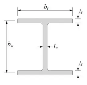
In this Section, the design equations for buckling resistance of thin-walled PFRP profiles are reported. Parameters bf and bw represent flange breadth and web depth, respectively, whereas tf = tw = t indicates the wall thickness, typically taking the same value for web and flange panels. In the case o an I-section profile, these dimensions are reported in Fig. 1, where bw corresponds to the distance between the flange centerlines.
Suggestions aimed at improving some of the equations provided by the Italian Guide are presented and discussed.
Compression
The nominal compressive resistance of a PFRP column usually takes the following form (see CNR, 2008, Equation 4.8):
R N loc
N =χ N (1)
where, Nloc is the nominal local buckling resistance and χN represents the buckling interaction coefficient (CNR, 2008, Equation 4.14):
Fig. 1. Cross-section of a PFRP I-profile
(
2 2)
2N N N cN N cN N
χ = Φ − Φ − λ λ (2)
In Equation (2), χN represents a nondimensional slenderness parameter, ΦN = (1+χN
2)/2 and c
N is a shape coefficient for the buckling curve. Taking account of the shear deformation on global buckling leads to the following expression for the slenderness parameter (Vanevenhoven et al., 2010; Laudiero et al., 2014):
loc Eng
N N N
λ = (3)
with NEng being the global buckling load given by Engesser's equation:
(
)
Eng Eul 1 Eul eff s
N =N + N G A (4)
In Equation (4), NEul is the Euler buckling load, As represents the shear area of the cross-section in the buckling plane and Geff indicates the effective (full-section) shear modulus. Equation (3) should be preferred to the analogous expression having NEul in the place of NEng (CNR, 2008, Equation 4.15) due to the shear flexibility of the pultruded material. The local buckling load is given by:
loc loc,c
N =Af (5)
with A and floc,c being cross-section area and local buckling stress, respectively. The recent trend of local buckling design is for the use of one single equation for the critical stress, so avoiding a discrete plate analysis with independent calculations for web and flange panels. In this context, it is proposed that Equations 4.10 to 4.13 and the whole Appendix A (Equations 7.1 to 7.12) are replaced with the following expression:
(
)
2 2 L loc,c cr,c LT TL w 12 1 E t f k b π ν ν = − (6)where, EL is the longitudinal plate bending modulus and νLT and νTL are major and minor Poisson's ratios. For an I-section column, according to the formulation proposed by Cardoso et al. (2015), the buckling coefficient appearing in Equation (6), kcr,c, takes the following form:
(
)
(
)
[
(
)(
)
cr,c T L LT T L f w LT TL LT L 2 2 2 1 4 1 k E E E E b b G E α α ν ν ν = + + + − (7) where, α = 1 + (π2/3)(bf/bw)3 and ET and GLT are transverse bending modulus and in-plane shear modulus, respectively, of the generic wall segment of the cross-section. It is worth noting that Equation (7) assumes the same material properties for all cross-section segments. However, the variational formulation used by Cardoso et al. (2015) to obtain Equation (7) can be modified to include different stiffnesses and thickness for web and flange panels. The accuracy of Equation (7) is comparable with that of very well known formulations derived from a discrete plate analysis, i.e., considering each panel as an independent plate in unidirectional compression and elastically restrained along the longitudinal edges in common with the adjacent panels.
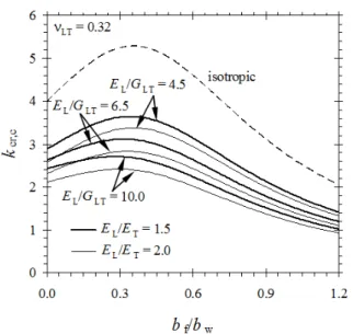
Buckling coefficient kcr,c is plotted in Fig. 2 versus bf/bw for νLT = 0.32 and different values of EL/ET and EL/GLT. The isotropic case is also shown in the figure. For bf/bw = 0 a value of kcr,c which approximates the buckling coefficient for the web simply supported at the web-flange junctions is recovered. For increasing values of bf/bw the transition occurs from a buckling mode triggered by web instability to another triggered by flange instability. The curves take a maximum at approximately bf/bw = 0.4. Usually commercial profiles present bf/bw lying in the range [0.55, 1.10].
Narrow-flange columns typically show a higher local buckling load in comparison with wide-flange columns with comparable cross-section area. On the contrary, as far as global buckling is concerned, wide-flange sections usually show a better performance due to their greater bending stiffness in the minor-axis plane. Therefore, at equal cross-section area, narrow- and wide-flange sections should be preferred for stocky and slender columns, respectively (see in particular Fig. 12 and Table 7 reported by Laudiero et al., 2014). Anyway, in the presence of geometric imperfections (in particular, out-of-straightness) of comparable amplitude, a unique design curve valid for both narrow- and wide-flange profiles can be defined.
Fig. 2. Local buckling coefficient for columns (Cardoso et al., 2015)
The value of the shape coefficient in Equation (2) recommended by the Italian Guide is cN = 0.65. Recent numerical studies (Laudiero et al., 2014) have shown that relatively reduced amplitudes of the initial imperfections like those measured on commercial profiles by Mottram et al. (2003) would make the PFRP columns not particularly sensitive to the buckling mode interaction and lead to ultimate column resistances in line with those evaluated from tests. Based on these studies, were these imperfection amplitudes not exceeded, a value cN = 0.8 could be used for a safe design. The pultruders are then invited to constantly check their production process in order to contain the geometric imperfections.
The outlined procedure (Equations 1 and 7) enables to define the compression resistance of I-section columns, but the general framework is believed to remain valid for all cross-sections. For cross-sections different from the I-section, suitable coefficients cN and kcr,c must be derived. In particular, experimental tests and/or numerical analyses like those performed by Laudiero et al. (2014) are recommended for estimating cN. The use of a variational approach like that used by Cardoso et al. (2015) is recommended for estimating
kcr,c. For example, similarly derived closed-form
expressions for kcr,c in the case of box, angle- and C-sections were presented by Cardoso et al. (2014).
For non standard sections, a geometrically nonlinear analysis with initial imperfection and check of the admissibility of the stress state through suitable failure criteria should always be performed to determine resisting axial load NR.
Bending
The nominal flexural resistance of a PFRP beam with doubly-symmetric cross-section in major-axis bending can be written in the form (CNR, 2008, Equation 4.21):
R M loc
M =χ M (8)
where, Mloc is the nominal local buckling moment and λM represents the buckling interaction coefficient (CNR, 2008, Equation 4.26):
(
2 2)
2M M M cM M cM M
χ = Φ − Φ − λ λ (9)
In Equation (9), πM represents a nondimensional slenderness parameter, ΦM = (1+λM
2)/2 and c
M is a shape coefficient for the buckling curve. Taking account of the shear deformation on global buckling leads to the following expression for the slenderness parameter (Laudiero et al., 2013): sd loc LT,pbd M M M λ = (10) with sd LT,pbd
M being the lateral-torsional buckling moment
accounting for the effects of shear deformation ("sd") and pre-buckling deflections ("pbd"). For simply-supported doubly-symmetric profiles in uniform major-axis bending, according to the proposal by Roberts
(2002), moment sd
LT,pbd
M can be estimated by means of the
following expression:
(
)
1 2sd 2 2
LT,pbd LT 1 min max eff min eff
M M I I π E I G AL
−
= − + (11)
where, MLT is the lateral-torsional buckling moment not accounting for the above-mentioned effects, which is given by:
(
)
(
2 2)
LT eff min DSV eff
M L E I G J E I L
ω
π π
= + (12)
and: Eeff = effective (full-section) longitudinal bending modulus; Imin, Imax = minor and major second moments of area of the cross-section; L = span length; GDSV = De Saint Venant's shear modulus, to be estimated from uniform torsion tests; and I = cross-section warping constant. Strictly speaking, due to inhomogeneity and orthotropic nature of the material, bending rigidities
( )
EI min,( )
EI max, minor-axis shear rigidity kGA, De
Saint Venant's torsional rigidity GJ and warping-torsion
rigidity EIω, possibly obtained from specifically
dedicated tests, should be used in Equations (11) and (12). However, for design purposes the more practical expressions reported above are believed to be acceptable.
A closed-form equation for the lateral-torsional buckling moment of doubly- and mono-symmetric composite beams with shear deformation, but ignoring pre-buckling deflections, was derived by Sapkás and Kollár (2002). With that equation, the buckling moment of both simply-supported and cantilever beams can be estimated simply changing some numerical coefficients. In particular, for simply-supported beams with span length L, approximations were provided for the following loading conditions: (1) uniform bending; (2) uniformly distributed lateral load; (3) concentrated force at midspan; and (4) concentrated forces at L/3 and 2L/3. For cantilever beams, approximations were provided for the following loading conditions: (1) uniformly distributed lateral load; and (2) concentrated tip force. The equation by Sapkás and Kollár (2002) takes also account of the distance between the point of application of the lateral loads and the cross-section shear centre.
Machado and Cortínez (2005) provided an accurate closed form expression for the estimate of sd
LT,pbd
M for
simply-supported doubly-symmetric profiles subjected to: (1) uniform bending; (2) a uniformly distributed lateral load; and (3) a concentrated force at midspan. Also this expression takes account of the location of the point of application of the lateral load relative to the shear centre. Machado and Cortínez's equation reduces to Sapkás and Kollár's equation when pre-buckling deflections are neglected.
Using geometrically-nonlinear FE analyses,
Nguyen et al. (2013) investigated the effects due to load position relative to the shear centre, warping fixity at the end sections and initial geometric imperfections on the lateral-torsional buckling of PFRP I-beams. With regard to the influence of the load position, they confirmed the results obtained by Sapkás and Kollár (2002) and Machado and Cortínez (2005). In particular, this influence is increased by the shear flexibility of the FRP material, leading to significant differences with respect to the shear centre loading case. For simply-supported beams with span-to-depth ratio L/h = 10 subjected to top flange loading, the ratio of the FE-computed buckling moment over the critical moment for shear centre loading is 11% lower than that obtained for steel beams. Analogously, for a beam subjected to bottom flange loading the ratio of the buckling moment over the critical moment for shear centre loading is up to 11% greater than the corresponding ratio for steel beams.
With regard to the effects of the end warping fixity for simply-supported PFRP beams with L/h between 10 and 50 loaded by a lateral point force at midspan, Nguyen et al. (2013) found a ratio of the critical moment for the end section warping being fixed to that obtained for free end section warping lying in the range [1.13, 1.66]. The analogous ratio for steel beams ranges between 1.07 and 1.48, indicating that also the warping effects are magnified by the shear flexibility.
Analogous results on the influence of load position and warping constraints were previously obtained numerically by Minghini et al. (2008).
With regard to the geometric imperfections, Nguyen et al. (2013) investigated the effects of out-of-straightness and twist. Their conclusions confirmed the results found by Laudiero et al. (2013), who analyzed the effects of an out-of-straightness defect: a
minor-axis out-of-straightness of appropriate
amplitude is the most practical imperfection to be modelled for analyzing lateral-torsional buckling. Nguyen et al. (2013) proposed to use an amplitude of L/200. However, such a value significantly exceeds the tolerances reported by CEN (2002). To avoid anti-economical design-related issues the imperfection amplitudes should be limited (see the discussions on this topic reported by Laudiero et al., 2013).
To locate, on the load-deflection response of PFRP imperfect beams, the limiting value of the lateral load corresponding to the onset of lateral-torsional buckling, Nguyen et al. (2013) proposed a secant stiffness reduction method. A stiffness reduction of 50% with respect to the initial stiffness is judged adequate.
Based on the previously reported considerations, it is believed that λM should be estimated using Equation (10)
with sd
LT,pbd
M obtained from the closed-form equation by
Machado and Cortínez (2005). For doubly-symmetric profiles subjected to load and constraint conditions different from those considered by Machado and Cortínez's equation and for mono-symmetric profiles with the major-axis plane being a plane of symmetry, it
is suggested that sd
LT,pbd
M estimates are obtained by
multiplying the relevant value of MLT by a modification factor according to Equation (11).
The local buckling moment is given by:
loc max loc,b
M =W f (13)
where, Wmax indicates the major-axis section modulus and floc,b is the local buckling stress.
Using an approach analogous to that applied by Cardoso et al. (2015) to PFRP columns, but taking account of (1) different material properties and (2) different thicknesses for web and flanges, Ascione et al. (2016) developed a closed-form expression for the critical stress for I-beams. Compared with other equations available in the literature, this expression provides the best correlation with the published experimental results on PFRP beams. Its predictive capacity was confirmed by the FE analysis results obtained for 48 wide-flange beams and 7 narrow-flange beams. Because of its "full-section" nature (the whole beam was considered in the governing variational problem), the equation by Ascione et al. (2016) does not require independent calculations for web and flanges.
In this study, in order to facilitate a direct comparison with Equations (6) and (7) relative to the compression case, the equation by Ascione et al. (2016) was rearranged and simplified by assuming: (1) a buckled flange with zero curvature in the transverse direction; and (2) identical thicknesses and material properties for web and flanges. Hence, the critical stress takes the form:
(
)
2 2 L loc,b cr,b LT TL w 12 1 E t f k b π ν ν = − (14)where, kcr,b is a local buckling coefficient given by:
(
)
(
)
{
(
)
(
)
(
)
}
(
)
2 2 cr,b f w LT TL LT L 3 2 4 2 f w T L 3 2 4 2 LT T L f w 8 24 2 3 2 1 33 2 2 3 3 2 6 k b b G E b b E E E E b b π π ν ν π π π π ν π π = + + − + + + − + + + − (15)Buckling coefficient kcr,b is plotted in Fig. 3 versus bf/bw for νLT = 0.32 and different values of EL/ET and EL/GLT. The isotropic case is also shown in the figure. For bf/bw = 0 a value of kcr,b which approximates the buckling coefficient for the web simply supported at the web-flange junction in compression and clamped at the web-flange junction in tension is recovered. The curves take a maximum at approximately bf/bw = 0.15. A detail of Fig. 3 for bf/bw ranging between 0.5 and 1.1 and kcr,b ≤ 30 is presented in Fig. 4.
The comparison between Fig. 2-4 immediately emphasizes that, at equal cross-section, the critical stress for local buckling in beams is much higher than in columns. For example, for bf/bw = 1.1, EL/ET = 2 and EL/GLT = 10, buckling coefficients kcr,c = 1.05 (Fig. 2) and kcr,b = 5.68 (Fig. 4) were obtained. This is essentially due to the stiffening effect exerted on the compression flange of beams by the part of the cross-section undergoing tensile stresses. Therefore, estimating the local flange buckling in beams with the same equations used for column instability certainly leads to a too conservative, anti-economical design. It is then suggested to replace design equations 4.23 to 4.25 in the Italian Guide (CNR, 2008) with Equations (14) and (15), or with their more general versions (Ascione et al., 2016) taking different thicknesses and material properties for web and flanges into account.
The value of the shape coefficient in Equation (9) recommended by the Italian Guide is cM = 0.7. Recent numerical studies (Laudiero et al., 2013) have shown that, in the presence of the imperfection amplitudes measured by Mottram et al. (2003) on commercial profiles, the PFRP beams are not particularly sensitive to the buckling mode interaction. Based on these studies, were these imperfections amplitudes not exceeded, a value cM = 0.9 could be used for a safe design.
Fig. 3. Local buckling coefficient for beams (Ascione et al., 2016)
Fig. 4. Detail of Fig. 3 for bf/bw ∈[0.5, 1.1] and kcr,b ≤30
The outlined procedure (Equations (8) and (15)) enables to define the bending resistance of I-section beams, but the general framework remains valid for all cross-sections. For cross-sections different from the I-section, suitable coefficients cM and kcr,b must be derived. In particular, numerical analyses like those performed by Laudiero et al. (2013) are recommended for estimating cM. The use of a variational approach like that used by Ascione et al. (2016) is recommended for estimating kcr,b. For non standard sections, a geometrically nonlinear analysis with initial imperfection and check of the admissibility of the stress state through suitable failure criteria should always be performed to determine MR.
Combined Axial Load and Bending
The Italian Guide provides the following three design equations for prismatic PFRP members subjected to combined axial load and uniaxial bending (see Equations 4.29-4.31): t,E E t,R R 1 N M N +M ≤ (16) c,E E c,R R 1 N M N +M ≤ (17)
(
)
c,E E c,R R c,E Eng 1 1 N M N +M −N N ≤ (18)In particular, Equation (16) refers to the case of a tensile axial load Nt,E combined with a constant bending
moment ME acting in a plane of symmetry (an equivalent
bending moment ME,eq should be used instead of ME in
the presence of nonuniform bending). Furthermore, Nt,R
and MR represent resisting tensile load and bending moment, evaluated on the basis of the material strengths. When stability should be checked, CNR (2008) suggests to ignore the first term on the left-hand side of Equation (16) and to proceed to a ULS verification in the presence of bending only. In this case, MR should be evaluated using Equation (8). In this study, it is proposed to use the whole procedure outlined in the previous subsection (Equations (8) and (15)) for I-section profiles).
Equation (17) refers to the case of a compression axial load Nc,E combined with a constant bending
moment ME acting in a plane of symmetry (once again,
an equivalent bending moment ME,eq should be used in the presence of nonuniform bending). Under the assumption that any possible instability mode is prevented, the resisting axial load and bending moment, Nc,R and MR, must be evaluated on the basis of the material strengths.
Equation (18) also refers to the case of a compression axial load Nc,E combined with a constant bending moment ME (or, alternatively, an equivalent bending moment ME,eq). In this case, however, instability is not considered to be prevented and suitable resisting axial load and bending moment must be used. In this study,
it is proposed to obtain Nc,R from Equation (1) and MR
from Equation (8). In particular, the whole procedures outlined in the previous two subsections (Equations (1) and (7) and Equations (8) and (15) for I-section profiles) should be adopted. Note that, differently
from Equation 4.31 of the Italian Guide, where NEul is
used in the denominator of the second term on the left-hand side, the use of NEng is proposed in Equation (18) to account for the shear deformation.
Equations (16) and (18) still need some numerical and experimental confirmation. The consideration of combined axial load and biaxial bending in future investigations is also hoped.
Web Panels Subjected to Concentrated Loads
Thin-walled beams subjected to concentrated loads in the plane of the web can collapse for stability or material failure. These failure mechanisms are influenced by both material and geometric properties, such as stiffnesses, thickness and depth of the web and distance of possible vertical web stiffeners.
In PFRP beams, the relatively low web transverse stiffness and web-flange junction strengths may magnify the trend toward web buckling and junction rupture, respectively. The studies available on this topic are few. However, the reduced capability of the pultruded material to resist point forces is known and some proposal for enhancing the beam capacity with the use of stiffening/strengthening systems was recently presented by Borowicz and Bank (2013). In that paper, an experimental campaign on beams with (1) full-depth web bearing stiffeners, (2) "doubler" plates attached to the web and (3) stiffening angles applied to the loaded web-flange junction was conducted. Web bearing stiffeners and web-flange junction stiffeners provided comparable increases (greater than 50%) in the ultimate capacity with respect to that of unstiffened control beams. The minimum increase in the ultimate beam capacity was obtained with the "doubler" plates (31.7%). Only the web-flange junction stiffeners were effective in avoiding failure in the loaded web-flange junction.
To avoid cross-section distortions under concentrated loads and at the simple supports in three- and four-point bending tests, Minghini et al. (2014) used wood stiffeners (Fig. 5).
In a recent experimental work, Borowicz and Bank (2014) tested five 609.5-mm deep PFRP beams (two made of vinylester and three of polyester resin) with a span-to-depth ratio of 4:1 in three-point bending. Each specimen experienced local web buckling followed by material failure in the loaded web-flange junction. Web buckling occurred on average at 90% of the ultimate load. Four different closed-form expressions for the local buckling web capacity were compared with one another in an attempt to propose a design method to be included into the American pre-standard (ASCE, 2011). The best correlation with the test results was obtained by calculating the ultimate load as follows:
w w
loc loc eff loc w
F = f A = f t a (19)
where, tw is the web thickness, a is taken as the lesser of the web depth and the distance between vertical web stiffeners (a = bw in the absence of web stiffeners) and
w loc
(
)
2 2 2 L T w w w loc 2 LT TL w 4 2 12 1 E E t b f b a π ν ν = + − (20)Borowicz and Bank (2014) found an average ratio of the experimental buckling load to the buckling load predicted using Equations (19) and (20) equal to 1.11 (1.24 for vinylester beams and 1.02 for polyester beams) and a coefficient of variation of 0.11.
The Italian Guide does not contain any design equation for the web buckling of PFRP beams under point forces. It is proposed that Equations (19) and (20) are implemented in a future revision of CNR-DT 205/2007.
Built-up Members
The emerging construction needs would require to gain insight into the response of built-up members.
Presently, there is a lack of scientific and technical literature on built-up members. Bai et al. (2013) performed four-point bending tests on built-up members used in the five-storey GFRP Eyecatcher building in Basel, Switzerland. That structure, built in 1999, still remains the tallest FRP building in the world. Its structural skeleton is comprised of three parallel trapezoidal GFRP frames connected by wooden decks. The various members of the frames were designed by assembling individual standard PFRP shapes by continuous bonding.
Boscato et al. (2015) presented interesting experimental results on the compression behavior of PFRP built-up columns comprised of four standard C-shaped profiles mutually connected at discrete points either by bolting or by bonding. In a first attempt to interpret the experimental results with simple closed-form equations, the authors compared the experimentally evaluated buckling loads with those estimated using (1) Euler's and (2) Engesser's equations (applied to the built-up columns considered as members with uniform cross-section) and (3) an expression typically adopted for steel built-up members. Unfortunately, none of these expressions was capable to predict the experimental buckling loads and the authors resolved that nonlinear FE analyses were necessarily to be performed to capture the actual column behavior.
Nevertheless, it is believed that a standard for PFRP structures cannot avoid to report some recommendation, design rule or equation for built-up members. Researchers are therefore encouraged to carry out round robin (experimental and/or numerical) tests on configurations of built-up sections possibly considering: • Various basic profiles (C- and L-shaped, etcetera)
• Different types of connection between basic profiles
(battens and or lacings, connected by bolting and/or bonding, etcetera)
• Changes in geometric characteristics (member total length, number of modules, etcetera)
• Various types of loading
Fig. 5. Wood stiffener used by Minghini et al. (2014)
Fig. 6. Built-up column of a temporary GFRP structure (Dicuonzo et al., 2012)
Fig. 7. Built-up members in the roof girder of a temporary GFRP structure (Dicuonzo et al., 2012)
For closely spaced built-up members, an important parameter that should be defined first is the maximum distance between the battens that ensures a buckling behavior typical of a single integral member. In steel construction, this parameter is usually set to 15imin, with imin being the minor-axis radius of gyration of one of the basic profiles comprising the built-up member (CEN, 2005). In view of the orthotropic nature of composite materials, a behavior of PFRP built-up members different from that of steel members is expected and a verification of this parameter is required.
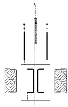
Fig. 8. Proposal for PFRP built-up member with steel and wooden interconnections
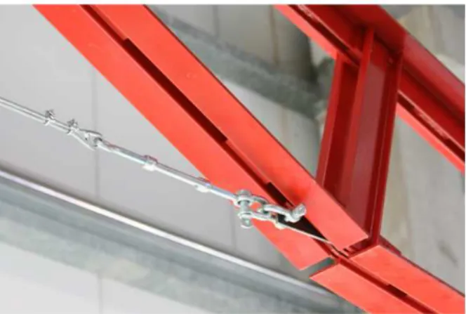
It is believed that systematic investigations should be carried out starting from closely spaced built-up members as those shown in Figs. 6 and 7. These profiles are part of a temporary, modular all-GFRP structure designed for an expo fair stand (Dicuonzo et al., 2008). In particular, the 3 m-high columns (Fig. 6) are comprised of two standard PFRP C-shaped profiles with dimensions 203 × 56 × 9.5 mm, connected with one another through 500 mm-spaced bonded battens. The modular, 6 span roof girders allow for covering 12 m-span lengths without requiring intermediate columns. Top and bottom chords of the roof girders (Fig. 7) are comprised of two standard PFRP equal-leg angles with dimensions 102 × 102 × 9.5 mm, once again connected with one another using bonded battens.
Another proposal for a PFRP built-up member using steel and wooden interconnections is shown in Fig. 8. Such a particular interconnection system allows for disassembling the built-up shape and does not require to drill holes in the pultruded shapes.
SLS Design
In addition to the limiting deflections provided by CNR (2008), it is believed that in a future revision of the guide attention should be paid to some aspects which have been the subject of recent investigations.
Effect of Geometric Imperfections
Ascione et al. (2015) analyzed the effect of initial geometric imperfections on pre-buckling deflections of simply-supported PFRP beams subjected to a uniformly distributed load in the major-axis plane using a geometrically nonlinear one-dimensional model. They investigated beams with span-to-depth ratios of 5, 10 and 15 and imperfection amplitudes of L/250, L/500 and L/1000. Moreover, they defined a limiting minor-axis deflection of L/400 and, for imperfect beams showing an initial minor-axis out-of-straightness, found significant reductions of the load corresponding to the attainment of the limiting deflection with respect to a reference perfect beam. Although no value of the three out-of-straightness imperfections has effect on the vertical beam displacements, at least for a lateral load approximately equal to 75% of the lateral-torsional buckling load (see Fig. 6 in Ascione et al., 2015) and minor-axis deflections may generally be limited or avoided in several structural applications (due to the presence of decks, for example), that finding means that geometric imperfections should in theory be included into SLS analyses.
The limiting imperfection amplitudes beyond which the influence of initial defects can be ignored in SLS design should suitably defined.
Effects of Load Redistribution
Turvey (2015) explored the possibility to redistribute point loads acting on PFRP beams at midspan in the form of a number of discrete loads, in order to enhance the "effective" beam flexural stiffness. In other words, it is recognized that in several applications the design of PFRP beams may be governed by the deflection serviceability limit. Then, rather than increasing the section depth or providing the beam flanges with stiffer carbon fibers (that may result in significant additional costs), it is proposed to redistribute the total load acting on a beam, so enhancing, at equal deflection limits, the load carrying capacity. Considerations on the best discrete load spacing were also provided.
Creep Effects
The reductions in the longitudinal and shear elastic moduli due to creep effects are accounted for in the Italian Guide through two creep coefficients. The values of these coefficients should be reviewed considering the recent findings by Bottoni et al. (2014).
Conclusion
Some update for design rules reported by guideline CNR DT-205/2007 on PFRP profiles is proposed. In particular, the general framework for the ULS design of columns and beams is outlined and a new equation providing the local buckling stress for I-beams in major-axis bending is presented.
The construction needs for gaining insight into the behavior of PFRP built-up members are recalled.
Future works will address possible updates of the Italian Guide relative to joint and connection design. In this context, a great number of recent experimental research findings is available (Turvey and Wang, 2007; Girão Coelho et al., 2015a; 2015b), as well as some numerical study on the effect of the joint behavior on the overall structural response (Minghini et al., 2009; 2010).
Funding Information
The authors gratefully acknowledge the financial support of the (Italian) National Civil Protection Department in the framework of the activities of the University Network of Seismic Engineering Laboratories (ReLUIS) - Progetto Esecutivo 2016 - Research Line
"Innovative Materials", grant No. (CUP):
F72I15000190005.
Author’s Contributions
All authors contributed equally to preparation of this paper.
Ethics
This paper contains unpublished material. All sources of information were properly referenced. The corresponding author confirms that all other authors have read and approved the manuscript and no ethical issue arose.
References
ASCE, 2011. Pre-standard for Load and Resistance Factor Design (LRFD) of pultruded Fiber Reinforced Polymer (FRP) structures. American Society of Civil Engineers.
Ascione, F. and G. Mancusi, 2013. The influence of the web-flange junction stiffness on the mechanical behaviour of thin-walled pultruded beams. Composites Part B: Engineering, 55: 599-606. DOI: 10.1016/j.compositesb.2013.07.021
Ascione, F., L. Feo, M. Lamberti, F. Minghini and N. Tullini, 2016. A closed-form equation for the local buckling moment of pultruded FRP I-beams in
major-axis bending. Composites Part B:
Engineering, 97: 292-299.
DOI: 10.1016/j.compositesb.2016.04.069
Ascione, L., V.P. Berardi, A. Giordano and S. Spadea, 2015. Pre-buckling imperfection sensitivity of pultruded FRP profiles. Composites Part B: Engineering, 72: 206-212.
DOI: 10.1016/j.compositesb.2010.12.014
Bai, Y., T. Keller and C. Wu, 2013. Pre-buckling and post-buckling failure at web-flange junction of pultruded GFRP beams. Materials Structures, 46: 1143-1154. DOI: 10.1617/s11527-012-9960-9 Bank, L.C. and J. Yin, 1999. Failure of web-flange
junction in postbuckled pultruded I-beams. J. Composites Construction, 3: 177-184.
DOI: 10.1061/(ASCE)1090-0268(1999)3:4(177) Borowicz, D.T. and L.C. Bank, 2013. Effect of web
reinforcement on the behavior of pultruded fiber-reinforced polymer beams subjected to concentrated loads. Construction Building Materials, 47: 347-357. DOI: 10.1016/j.conbuildmat.2013.05.081
Borowicz, D.T. and L.C. Bank, 2014. Web buckling in pultruded fiber-reinforced polymer deep beams subjected to concentrated loads. J. Composites Construction.
DOI: 10.1061/(ASCE)CC.1943-5614.0000360. Boscato, G., C. Casalegno and S. Russo, 2015. Performance
of built-up columns made by pultruded FRP material. Composite Structures, 121: 46-63.
DOI: 10.1016/j.compstruct.2014.11.022
Bottoni, M., C. Mazzotti and M. Savoia, 2014. Creep tests on GFRP pultruded specimens subjected to traction and shear. Composite Structures, 108: 514-523. DOI: 10.1016/j.compstruct.2013.09.057
Cardoso, D.C.T., K.A. Harries and E.D.M. Batista, 2014. Closed-form equations for compressive local buckling of pultruded thin-walled sections. Thin-Walled Structures, 79: 16-22.
DOI: 10.1016/j.tws.2014.01.013
Cardoso, D.C.T., K.A. Harries and E.D.M. Batista, 2015. Compressive local buckling of pultruded GFRP I-sections: development and numerical/experimental evaluation of an explicit equation. J. Composites Construction.
DOI: 10.1061/(ASCE)CC.1943-5614.0000501
CEN (2002). Reinforced plastics composites
-Specifications for pultruded profiles - Part 2: Method of test and general requirements. EN 13706-2:2002, Brussels, Belgium.
CEN (2005). Eurocode 3: Design of steel structures - Part 1-1: General rules and rules for buildings. EN 1993-1-1:2005, Brussels, Belgium.
CNR, 2008. Guide for the design and construction of structures made of FRP pultruded elements. CNR-DT 205/2007, www.cnr.it.
Dicuonzo, A., F. Laudiero, F. Minghini, N. Tullini and F. Maceri, 2008. Design and construction of a temporary structure composed by FRP pultruded profiles. Proceedings of the 4th International Conference on FRP Composites in Civil Engineering (CICE2008), July 22-24, Zurich, Switzerland, pp: 1-6.
Fairuz, A.M., S.M. Sapuan, E.S. Zainudin and C.N.A. Jaafar, 2014. Polymer composite manufacturing using a pultrusion process: A review. Am. J. Applied Sciences, 11: 1798-1810.
DOI: 10.3844/ajassp.2014.1798.1810
Feo, L., A.S. Mosallam and R. Penna, 2013. Mechanical behavior of web-flange junctions of thin-walled pultruded I-profiles: An experimental and numerical evaluation. Composites Part B: Engineering, 48: 18-39. DOI: 10.1016/j.compositesb.2012.11.001
Girão Coelho, A.M. and J.T. Mottram, 2015a. A review of the behaviour and analysis of bolted connections and joints in pultruded fibre reinforced polymers. Materials Design, 74: 86-107.
DOI: 10.1016/j.matdes.2015.02.011
Girão Coelho, A.M., J.T. Mottram and K.A. Harries, 2015b. Bolted connections of pultruded GFRP: Implications of geometric characteristics on net section failure. Composite Structures, 131: 878-884.
DOI: 10.1016/j.compstruct.2015.06.048
Laudiero, F., F. Minghini and N. Tullini, 2013. Postbuckling failure analysis of pultruded FRP beams under uniform bending. Composites Part B: Engineering, 54: 431-438.
DOI: 10.1016/j.compositesb.2013.06.009
Laudiero, F., F. Minghini and N. Tullini, 2014. Buckling and postbuckling finite-element analysis of pultruded FRP profiles under pure compression. J. Composites Construction, 18: 04013026.
DOI: 10.1061/(ASCE)CC.1943-5614.0000384 Machado, S.P. and V.H. Cortínez, 2005. Lateral
buckling of thin-walled bisymmetric beams with prebuckling and shear deformation. Engineering Structures, 27: 1185-1196.
DOI: 10.1016/j.engstruct.2005.02.018
Minghini, F., N. Tullini and F. Laudiero, 2008. Buckling analysis of FRP pultruded frames using locking-free finite elements. Thin-Walled Structures, 46: 223-241. DOI: 10.1016/j.tws.2007.09.001
Minghini, F., N. Tullini and F. Laudiero, 2009. Elastic buckling analysis of pultruded FRP portal frames
having semi-rigid connections. Engineering
Structures, 31: 292-299.
DOI: 10.1016/j.engstruct.2008.09.003
Minghini, F., N. Tullini and F. Laudiero, 2010. Vibration analysis of pultruded FRP frames with semi-rigid connections. Engineering Structures, 32: 3344-3354. DOI: 10.1016/j.engstruct.2010.07.008
Minghini, F., N. Tullini and F. Laudiero, 2014. Identification of the short-term full-section moduli of pultruded FRP profiles using bending tests. J. Composites Construction.
DOI: 10.1061/(ASCE)CC.1943-5614.0000391
Mosallam, A.S., L. Feo, A. Elsadek, S. Pul and R. Penna, 2014. Structural evaluation of axial and rotational flexibility and strength of web-flange junctions of open-web pultruded composites. Composites Part B: Engineering, 66: 311-327. DOI: 10.1016/j.compositesb.2014.05.018
Mottram, J.T., N.D. Brown and D. Anderson, 2003. Physical testing for concentrically loaded columns of pultruded glass fibre reinforced plastic profile. Proceedings of the Institution of Civil Engineers - Structures and Buildings, 156 (2): 205-219.
DOI: 10.1680/stbu.2003.156.2.205.
Nguyen, T.T., T.M. Chan and J.T. Mottram, 2013. Influence of boundary conditions and geometric
imperfections on lateral-torsional buckling
resistance of a pultruded FRP I-beam by FEA. Composite Structures, 100: 233-242.
DOI: 10.1016/j.compstruct.2012.12.023
Roberts, T.M., 2002. Influence of shear deformation on buckling of pultruded fiber reinforced plastic profiles. J. Composites Construction, 6: 241-248. DOI: 10.1061/(ASCE)1090-0268(2002)6:4(241) Sapkás, Á. and L.P. Kollár, 2002. Lateral-torsional
buckling of composite beams. Int. J. Solids Structures, 39: 2939-2963.
DOI: 10.1016/S0020-7683(02)00236-6
Turvey, G.J. and P. Wang, 2007. Failure of pultruded GRP single-bolt tension joints under hot-wet conditions. Composite Structures, 77: 514-520. DOI: 10.1016/j.compstruct.2005.08.024
Turvey, G.J. and Y. Zhang, 2006a. A computational and experimental analysis of the buckling, postbuckling and initial failure of pultruded GRP columns. Computers Structures, 84: 1527-1537.
DOI: 10.1016/j.compostruc.2006.01.028
Turvey, G.J. and Y. Zhang, 2006b. Characterisation of the rotational stiffness and strength of web-flange junctions of pultruded GRP WF-sections via web bending tests. Composites Part A: Applied Science Manufacturing, 37: 152-164.
DOI: 10.1016/ j.compositesa.2005.04.022
Turvey, G.J., 2015. Enhancing the load capacity of pultruded GFRP beams via discrete load redistribution. Composite Structures, 122: 352-360. DOI: 10.1016/j.compstruct.2014.11.066
Vanevenhoven, L.M., C.K. Shield and L.C. Bank, 2010. LRFD factors for pultruded wide-flange columns. J. Structural Engineering, 136: 554-564.