1
Università degli Studi di Ferrara
DOTTORATO DI RICERCA IN
FISICA
CICLO XXVII
COORDINATORE Prof. Vincenzo Guidi
Crystals with curved diffracting planes for
hard X-ray optics
Settore Scientifico Disciplinare FIS/03
Dottorando Tutore
Dott. Bellucci Valerio Prof. Guidi Vincenzo
_______________________________ _____________________________
(firma) (firma)
3
CONTENTS
LIST OF FIGURES ... 7
ABSTRACT ... 11
1 INTRODUCTION TO DIFFRACTIVE OPTICS ... 13
1.1 BACKGROUND – INSTRUMENTATION FOR X AND GAMMA RAY OPTICS ... 13
1.1.1 COLLIMATORS ... 13
1.1.2 MONOCHROMATORS ... 15
1.1.3 POLARIZERS ... 16
1.1.4 CODED MASKS ... 17
1.1.5 GRAZING INCIDENCE MIRRORS... 18
1.1.6 SUPERMIRRORS ... 20
1.1.7 FRESNEL ZONE PLATES ... 22
1.1.8 COMPOUND REFRACTIVE LENSES ... 22
1.1.9 POLICAPILLARITY LENSES ... 24
1.1.10 LAUE LENSES ... 25
1.2 CRYSTALS FOR DIFFRACTIVE OPTICS ... 28
1.2.1 GENERALITIES OF CRYSTALS ... 28
1.2.2 PERFECT FLAT CRYSTALS ... 30
1.2.3 MOSAIC CRYSTALS ... 30
1.2.4 CURVED DIFFRACTING PLANES (CDPS) CRYSTALS ... 32
1.2.5 STATE OF THE ART FOR CDPS CRYSTALS PRODUCTION ... 32
1.3 THEORY OF DIFFRACTION ... 35
1.3.1 KINETIC THEORY OF DIFFRACTION ... 35
1.3.1.1 X-ray diffraction basics ... 35
1.3.1.2 Form factors ... 39
1.3.1.3 Diffraction by a Small Crystal ... 41
1.3.1.4 Temperature of a crystal ... 43
1.3.1.5 Polarizability of matter ... 46
1.3.1.6 Absorption ... 47
1.3.2 DYNAMICAL THEORY OF DIFFRACTION ... 48
1.3.2.1 Fundamentals ... 48
1.3.2.2 Uniformly curved diffraction planes (CDPs) ... 54
2 EXTENSION OF THE DYNAMICAL THEORY ... 56
2.1 THEORETICAL AND MODELLING ... 57
2.2 EXPERIMENTAL AND CONCLUSIONS ... 62
3 THE LAUE PROJECT ... 66
3.1 BACKGROUND –APPLICATIONS OF X-RAY LENSES ... 68
3.2 THEORETICAL PERFORMANCES OF CDPS CRYSTALS ... 73
4
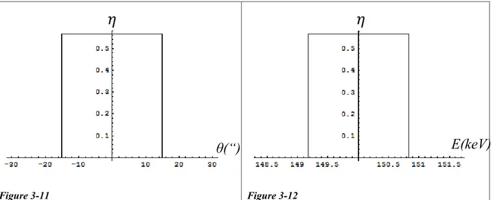
3.2.1.1 Local efficiency ... 73
3.2.1.2 Integrated reflectivity & integrated spreading ... 77
3.2.1.3 Corrections for real conditions ... 79
3.2.2 QUASI-MOSAIC CDPS ... 80
3.2.2.1 Modelling the quasi-mosaic curvature ... 80
3.2.2.2 Total efficiency ... 82
3.2.2.3 Focusing properties ... 83
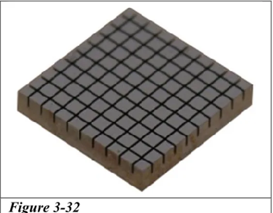
3.3 THE INDENTATION METHOD AND OUR CRYSTALS ... 89
3.3.1 THE INDENTATION METHOD ... 89
3.3.2 EARLY EXPERIMENTATION WITH PRIMARY CDPS CRYSTALS... 91
3.3.3 EARLY EXPERIMENTATION WITH QUASI-MOSAIC CDPS CRYSTALS ... 96
3.4 CRYSTALS FOR THE LAUE PROJECT ... 98
3.4.1 PRODUCTION ... 98
3.4.2 TESTS AT ESRF/ILL FACILITIES ... 99
3.4.2.1 ID15 ... 99
3.4.2.2 White-light diffractometer... 100
3.4.3 TESTS AT LARIX FACILITY... 103
3.5 VERY THICK GROOVED CRYSTALS ... 109
4 INNOVATIVE CRYSTALS FOR HARD X-RAY LENSES ... 113
4.1 CRYSTALS WITH NON-STANDARD QUASI-MOSAIC REFLECTIONS –(422) AND (311) ... 114
4.2 TENSILE FILMS FOR PRODUCING CDPS CRYSTALS ... 122
4.2.1 THIN FILMS ... 123
4.2.2 THICK FILMS -CFRP ... 125
4.2.3 ION IMPLANTATION ... 128
4.3 MULTI-CRYSTALS ... 136
4.3.1 DESIGN OF MULTI-CRYSTALS ... 137
4.3.1.1 Primary CDPs multi-crystals ... 137
4.3.1.2 Quasi-mosaic CDPs multi-crystals ... 138
4.3.2 EXPERIMENTAL &METHODS ... 139
4.3.2.1 Stack of grooved crystals ... 139
4.3.2.2 Stack of lamellae ... 147
4.4 TILTED CDPS CRYSTALS ... 152
4.4.1 THEORETICAL ... 153
4.4.2 USE OF ASYMMETRIC CDPS ... 155
4.4.3 USE OF SKEW CDPS ... 160
5 PARAMETRIC X-RAY RADIATION (PXR) IN LAUE LENSES ... 163
5.1 THEORY OF PXR ... 164
5.2 FLUX OF COSMIC RAYS ON A LAUE LENS ... 166
5.3 PXR EMISSION BY A THIN FLAT CRYSTAL ... 167
5.4 PXR EMISSION BY A THICK CDPS CRYSTAL ... 167
5.5 RESULTS ... 170
6 CRYSTALLINE UNDULATOR ... 171
CONCLUSIONS ... 175
5
7.1 BASIC CONCEPTS ... 177
7.2 DISPLACEMENT FIELD OF A FLEXED BAR ... 182
7.3 DISPLACEMENT FIELD OF A SQUARE FLEXED PLATE ... 186
7.4 DISPLACEMENT FIELD OF A RECTANGULAR FLEXED PLATE ... 193
7.5 VARIATION OF INTERPLANAR SPACING ... 194
8 APPENDIX II – LIST OF PUBLICATIONS... 195
7
List of figures
Figure 1-1 ... 14 Figure 1-2 ... 15 Figure 1-3 ... 15 Figure 1-4 ... 18 Figure 1-5 ... 19 Figure 1-6 ... 20 Figure 1-7 ... 20 Figure 1-8 ... 21 Figure 1-9 ... 22 Figure 1-10 ... 23 Figure 1-11 ... 23 Figure 1-12 ... 24 Figure 1-13 ... 25 Figure 1-14 ... 25 Figure 1-15 ... 25 Figure 1-16 ... 26 Figure 1-17 ... 26 Figure 1-18 ... 28 Figure 1-19 ... 28 Figure 1-20 ... 29 Figure 1-21 ... 29 Figure 1-22 ... 30 Figure 1-23 ... 31 Figure 1-24 ... 31 Figure 1-25 ... 32 Figure 1-26 ... 33 Figure 1-27 ... 34 Figure 1-28 ... 34 Figure 1-29 ... 35 Figure 1-30 ... 37 Figure 1-31 ... 38 Figure 1-32 ... 39 Figure 1-33 ... 39 Figure 1-34 ... 42 Figure 1-35 ... 48 Figure 1-36 ... 49 Figure 1-37 ... 51 Figure 1-38 ... 52 Figure 1-39 ... 53 Figure 1-40 ... 53 Figure 1-41 ... 54 Figure 1-42 ... 54 Figure 2-1 ... 588 Figure 2-2 ...59 Figure 2-3 ...61 Figure 2-4 ...62 Figure 2-5 ...63 Figure 2-6 ...64 Figure 2-7 ...65 Figure 3-1 ...66 Figure 3-2 ...67 Figure 3-3 ...67 Figure 3-4 ...69 Figure 3-5 ...70 Figure 3-6 ...71 Figure 3-7 ...72 Figure 3-8 ...73 Figure 3-9 ...74 Figure 3-10 ...74 Figure 3-11 ...75 Figure 3-12 ...75 Figure 3-13 ...76 Figure 3-14 ...77 Figure 3-15 ...78 Figure 3-16 ...78 Figure 3-17 ...79 Figure 3-18 ...79 Figure 3-19 ...80 Figure 3-20 ...81 Figure 3-21 ...82 Figure 3-22 ...83 Figure 3-23 ...83 Figure 3-24 ...83 Figure 3-25 ...84 Figure 3-26 ...84 Figure 3-27 ...85 Figure 3-28 ...85 Figure 3-29 ...86 Figure 3-30 ...86 Figure 3-31 ...87 Figure 3-32 ...89 Figure 3-33 ...90 Figure 3-34 ...91 Figure 3-35 ...92 Figure 3-36 ...93 Figure 3-37 ...94 Figure 3-38 ...95 Figure 3-39 ...95 Figure 3-40 ...96 Figure 3-41 ...97
9 Figure 3-42 ... 98 Figure 3-43 ... 98 Figure 3-44 ... 100 Figure 3-45 ... 102 Figure 3-46 ... 103 Figure 3-47 ... 104 Figure 3-48 ... 106 Figure 3-49 ... 106 Figure 3-50 ... 107 Figure 3-51 ... 107 Figure 3-52 ... 108 Figure 3-53 ... 109 Figure 3-54 ... 110 Figure 3-55 ... 111 Figure 4-1 ... 115 Figure 4-2 ... 115 Figure 4-3 ... 116 Figure 4-4 ... 117 Figure 4-5 ... 118 Figure 4-6 ... 118 Figure 4-7 ... 118 Figure 4-8 ... 118 Figure 4-9 ... 120 Figure 4-10 ... 120 Figure 4-11 ... 120 Figure 4-12 ... 120 Figure 4-13 ... 121 Figure 4-14 ... 126 Figure 4-15 ... 127 Figure 4-16 ... 128 Figure 4-17 ... 129 Figure 4-18 ... 130 Figure 4-19 ... 131 Figure 4-20 ... 132 Figure 4-21 ... 134 Figure 4-22 ... 135 Figure 4-23 ... 137 Figure 4-24 ... 138 Figure 4-25 ... 139 Figure 4-26 ... 140 Figure 4-27 ... 141 Figure 4-28 ... 142 Figure 4-29 ... 143 Figure 4-30 ... 144 Figure 4-31 ... 146 Figure 4-32 ... 146 Figure 4-33 ... 147
10 Figure 4-34 ...148 Figure 4-35 ...149 Figure 4-36 ...151 Figure 4-37 ...152 Figure 4-38 ...153 Figure 4-39 ...157 Figure 4-40 ...158 Figure 4-41 ...159 Figure 4-42 ...160 Figure 4-43 ...161 Figure 4-44 ...162 Figure 5-1 ...165 Figure 5-2 ...166 Figure 5-3 ...170 Figure 6-1 ...172 Figure 6-2 ...173
11
Abstract
Crystals with curved diffraction planes (CDP crystals) are an emerging technology in hard X-ray optics. Through them, it is possible to condition hard X-ray beams with high energy efficiency and flexibility. Optical instruments for visible light are not effective to manipulate high-energy radiation. In fact, the phenomena of reflection and refraction on which they are based become unimportant for electromagnetic waves with high energy. For this reason, optics of hard X-rays and gamma rays has been up to now based direct view instruments.
In contrast, diffraction phenomena can be important even at high energies. Therefore, it is possible to condition hard X-ray beams by Bragg diffraction. Bragg diffraction is called Laue diffraction when the electromagnetic wave goes through the crystal. Due to the length of penetration of high-energy photons, this configuration appears to be preferable than diffraction in reflection geometry (Bragg diffraction). Recently, optical systems have been developed based on perfect crystals or mosaic crystals. However, instruments based on these materials have constructive difficulties, poor reproducibility, and finally a limited efficiency.
Crystals with curved lattice planes have an efficiency in the manipulation of X-rays that approaches the unity. Through the curvature of their plans, they offer a continuum of possible angles of diffraction to incident radiation. Thus, the curvature of planes allows to influence photons in a wide range of energies. It is also possible to apply more than one curvature to a single crystal, deforming the symmetry, thus turning it into a focusing element.
The curved crystals have elective application in the construction of lenses for hard X-rays (Laue lenses), composed by a set of crystal with diffraction planes oriented towards a common point, so as to diffract the incident radiation towards the focus of the lens. This tool is especially useful in the field of astrophysics and medical physics. The observation of the sky over energy of 70 keV is still left to direct view instruments. These have a low angular resolution, a low signal to noise ratio, and a high weight, which is an important parameter because the observation of X-rays is only possible out of the atmosphere. The cosmic sources of X-rays produce a very low flux of photons, so the signal to noise ratio of the instrument becomes a key factor for the investigation of these sources. Today, only the spectra of the most intense sources are known at energies above 70 keV.
Another discipline that can benefit from the use of CDPs crystals is nuclear medicine. Indeed, it would be possible to increase the sensitivity and accuracy of instruments for nuclear medicine by using focusing optics based on curved crystals. The spatial resolution of the instrument would be increased to a sub-millimeter precision, with which it would be possible to accurately locate tumors and other phenomena of interest, and to provide more information on the same. Due to the high reflectivity of the CDPs crystals, even the number of photons that can be collected on the detector would be increased, with a consequent improvement in the sensitivity of the instrument, and a decrease in the dose of radio-drug to be injected into the patient.
The formalism developed so far under the dynamical theory of diffraction allows to describe effectively crystals with flat diffraction planes, or crystals with diffraction planes strongly deformed. Various applications require CDPs with low curvatures, in particular when crystals with high atomic number are used. In this case, the formalism of dynamical theory is not applicable in a simple way. To know the performance of the CDPs crystals in these areas of application, it is necessary the
12
development of a treatment dedicated to the purpose. The theoretical work has touched the development of the dynamic theory of diffraction in order to cover its weaknesses for CDPs with low curvature.
The work of technological development and construction of hardware for scientific research focused on the development and production of innovative crystals for the construction of hard X-ray lenses. The construction of Laue lenses has been simplified with the introduction of focusing crystals. The thesis work was partially carried out within the LAUE Project, funded by ASI, whose purpose was the construction of a large-area Laue lenses. The work done during the doctoral thesis has led to a rethinking of the project in order to use focusing crystals and thus to increase the resolution and sensitivity of the lens.
The work on crystals for Laue lenses did not end with the LAUE Project, but it continued with a series of technological innovations with the aim to increase the maximum resolution and sensitivity achievable by Laue lenses. These innovations include the introduction of crystals with multiple curvatures and focusing crystals, the study of novel methods with which to produce crystals with CDPs, the construction of stacks of multi-crystals, the use of curved asymmetric diffraction planes. The experimental tests were performed at the facilities of ESRF (European Synchrotron Radiation Facility, Grenoble, France), ILL (Institut Laue-Langevin, Grenoble, France) and LARIX (LARge Italian X-ray facility, Ferrara, Italy).
Simulations were also performed to estimate the possible interferences that a Laue lens could suffer in orbit because of the interaction with cosmic rays and the consequent production of parametric X-rays. This source of X-rays may interfere with measurements of celestial X-ray sources. The work has led to the exclusion of this possibility, since the emission of parametric X-rays would be less than the sensitivity of the lens itself.
Finally, the technologies developed to produce CDPs crystals were used for the construction of a crystalline undulator built as a prototype of X-ray source with high-energy and high flux. Lattice planes of a crystals where shaped in an undulated structure. Characterization of these lattice planes showed near-ideal results. High-energy charged particles channeled through these planes would produce coherent X-rays. The prototype will be part of an experiment at the SLAC accelerator (San Francisco, USA).
13
1
Introduction to diffractive optics
1.1 Background – instrumentation for X and
Gamma ray optics
The lenses used to manipulate visible light are composed of transparent material with refractive index significantly different from 1. There are no materials with similar properties when the energy of electromagnetic waves reaches the X-ray or gamma ray band. In fact, in this energy band the refractive index of materials is very near to 1. The mirrors that are used to manipulate visible or ultraviolet light have a low efficiency too in reflecting X-rays. Indeed, photons of high energy poorly interact with matter. It is possible to build mirrors that reflect X-rays up to 70 keV, but the reflection occurs only if the angle of incidence with the surface of the mirror is very small, usually between 10 arcmin and 2 degrees. Currently, the most efficient tools to manipulate X-rays are collimators and monochromators, while solid state or gas detectors are used for the detection of photons.
In recent years there have been many efforts on the development of optics for hard X-rays based on Bragg diffraction, using crystals as active elements for manipulating X and gamma rays. Diffraction is a phenomenon very efficient for photons of energy from a few keV to 1 MeV. Diffraction allows to treat the beam without reducing too much the intensity of the same, and without the need overly complex systems. The high efficiency of diffraction phenomena also allows manipulating X-rays with incidence angle near to the normal to the surface of the optical apparatus. Thus, it is possible to substantially reduce the size of the instrument itself. This type of diffraction is called Laue diffraction, and occurs by interaction of the radiation with lattice planes crossing the crystal. Lenses of this type were initially developed for astronomy in the X-ray band, but they soon found applications in nuclear medicine too. Here are some tools used in X-ray optics up to the latest developments, and some applications of the same.
1.1.1
Collimators
Collimators are mechanical devices for stopping part of the photons that pass through the collimator itself. The simplest type of collimator is a plate of absorbent material with an opening with size equal to the desidered size of the exit beam. Usually collimators are made of materials with high atomic number so as to present a high rate of absorption to incident radiation (the most common materials are Lead or Tungsten). Additionally, materials that do not present edge absorption or fluorescence in the range of energies of the incident photons are preferred. Indeed, materials with an absorption edge would result in the production of radiation by the same collimator. When this choice is not possible, it is necessary the use of collimators made up of layers of different materials, which are chosen in such a way as to mitigate the fluorescence.
The collimators are used to manipulate beams of X-rays, or to increase the resolution of detectors. X-ray sources produce emission with spatial dimensions too high to be usable. Collimators are used to reduce the size and the divergence of the beam (as well as monochromators) so as to obtain a useful beam size and divergence. This configuration is widely used in experiments that use artificial X-ray sources. For example, if you use X-rays to analyze a sample, it is useful to have a beam as narrow as possible and free of divergence, to ensure high resolution and a precise analysis.
14
Often the collimators used for these purposes have adjustable openings made by mobile slits, in order to vary the size of the beam at the exit of the collimator.
Collimators are used in detectors to limit their angle of view, so to have directional information from the measured radiation, increasing the resolution and reducing the background noise caused by photons from other directions. For this application, the simplest collimators have the shape of a box or of a pipe open at the ends, at one end the sensing face of the detector is located. In Figure 1-1, if A is the area of the sensitive face of the detector, equal to the opening of the collimator, and h is the height of the collimator, the solid angle observable will be about A/h2, centered around the axis of the
collimator. The photons that originate from an angle outside of this field of view impinge on the walls of the collimator and they are absorbed. If the collimator does not present cylindrical symmetry around the center of the detector, the angle of view θ changes with the variation of the angle φ around the axis of the collimator.
Collimators with this geometry are used in X-ray astronomy. In this case, the collimators must meet three requirements. The first requirement is to be as absorptive as possible, to block the photons out of the angle of view. The last requirements are to be light and not very bulky, to be easy to use in balloon or satellite experiments. In some cases, it is
necessary to place on top of the detector a collimator of a complex shape (ex. Figure 1-2) that covers part of the detector. In this case it is even more important that the collimator is not bulky, to ensure a wide opening for the photons inside the angle of view. Usually the absorption of a material increases with its atomic number, and therefore of its weight. Therefore, it is necessary to optimize the thickness of the walls of the collimator in order to find a compromise between the requirements. For example, in the case of the detector PDS mounted on BeppoSAX (Orlandini, 2008/2009), it was used a collimator consists of pipes of Tantalum with hexagonal section, with length of 20 cm and thickness of 50 μm. The inside of the tubes was covered with a double layer of tin (100 pM) and Copper (50 um) in the first 4 cm from the base. The layer of tin had the purpose of mitigating the fluorescence emission from the K shell of tantalum (Kα = 57.07 keV, Kβ = 65.56 keV) while the copper layer attenuates the X-ray emission by fluorescence from tin (Kα = 25.1 keV, Kβ = 28.5 keV). This configuration is called grading shielding, and it allowed to keep 80% of the effective area of the detector.
Figure 1-1
Simple example of a collimator (in gray), where A is the sensitive area of the detector, h is the distance between the detector and the opening of the collimator.
15
Figure 1-2
Collimator made of a series of rectangular tubes, height h and section a × b. This collimator was placed on the detector PDS mounted on BeppoSAX (Orlandini, 2008/2009). The X-rays that strike the walls of the collimator do not reach the detector. The field of view has a different extension in the two perpendicular directions, with φ = arctg(b/h), θ = arctg(a/h).
1.1.2
Monochromators
Most of artificial X-ray sources produces polychromatic radiation with high divergence, and high spatial extension. For example, an X-ray tube emits radiation in the typical continuous spectrum of Bremsstrahlung. The photons are emitted in all directions, but with preferential direction towards the exit of the tube, thus producing a beam with large divergence and large spatial extent. A synchrotron produces radiation with less divergence and spatial extent, but not enough to be used in most of the experiments. It is possible to partially reduce the divergence and the spatial extent of a beam by collimators, but collimators do not allow to reduce the range of energies contained in a
beam. Indeed, it is necessary to introduce at least a monochromator in the system to obtain a highly monochromatic (high energy resolution) and low divergence (high angular resolution) photon flux. A monochromator is composed of one or more crystals. An X-ray beam enters the monochromator and it undergoes multiple Bragg diffraction (at least two diffraction) by the lattice planes of the crystals composing the monochromator. Only the photons entering the monochromator at a certain angle and at a certain energy, defined by Bragg's law nλ = 2dsinθ n = nhc/E, undergo diffraction by
Figure 1-3
Examples of monochromators (Authier A. , 2001). (a) monochromator composed of two crystal, the output direction of the beam is fixed. (b) channel-cut monochromator with four reflections, with fixed output beam.
16
all the crystals composing the monochromator, thus they exit the monochromator without being absorbed. Usually the monochromators consists of perfect crystals, whose angle tolerance for diffraction (and therefore the tolerance in energy) is equal to the Darwin width δw. In good
monochromators the divergence of the output beam is equal to or less than the Darwin width of the material used in the monochromator. The energy spectrum of the photons that constitute the beam is cut, and only a small energy band can pass. Many types of monochromators exist, each type best suits the analysis to perform (Figure 1-3).
1.1.3
Polarizers
Many experiments require X-rays with linear or circular polarization. As an example, measurements on magnetic materials for the detection of X-ray magnetic scattering, or for the detection of the signal of X- Ray Magnetic Circular Dichroism (XMCD) or of X-Ray Magnetic Linear Dichroism (XMLD) require linear or circular polarization. In the first case, the fact that the scattering cross section contains also a term of magnetic origin (Hannon, 1988) allows measurements of diffraction or reflectivity highlighting both the contributions of structural origin and those of a magnetic nature. Therefore, it is possible to derived structural information about the order, and on the magnetic field by working near the absorption thresholds (Wilkins, 2003). In the last two cases (XMCD and XMLD), measurements are made by recording the absorption spectra close to the absorption thresholds of the material to be studied. The XMCD signal is obtained by taking the difference between the absorption spectrum collected with radiation with circular right polarization and the radiation collected with circular left polarization. This procedure allows to obtain the value of the magnetic moment. Conversely, the XMLD signal is obtained by comparing the absorption spectra obtained with two linear polarizations orthogonal to each other. The difference between XMCD and XMLD lies in the fact that the first is used to study ferromagnetic materials, while the second is used to study the antiferromagnetic type materials (Kuiper, 1993) (Stöhr, 1999).
Synchrotron radiation is plane polarized in the plane of the orbit, while it becomes elliptically polarized far from this plane. Radiation from X-ray tubes is unpolarized, but it can be polarized using phase retarders or Bragg diffraction. Linear polarization is achieve by eliminating one of the two components of the polarization. Different types of polarizers have been used to achieve this result. The two polarization directions have different absorption coefficients near the Bragg angle. In this case, one of the two absorption coefficient is much larger than the other one, then the part of the X-ray beam polarized in that direction is completely absorbed (Staudenmann, 1985). Another type of linear polarizer take advantage of Bragg diffraction. Lattice planes for which the Bragg angle is close to π/4 cannot diffract the π-polarized component of the X-ray beam, so only the σ-polarized components is diffracted (Chandrasekaran, 1959). This method cannot be used for hard X-rays because the Bragg diffraction angle becomes too small. However, even at high energy the two polarization directions are diffracted with different efficiency. Then, linear polarization is attained by multiple diffractions in channel-cut crystals (Sato, 2000). Single-crystal phase retarders are used to attain circularly polarized X-rays. X-ray birefringence occurs in a perfect crystal that is oriented in the near of a Bragg reflection, giving rise to phase shifts between the σ and π polarization components of the beams propagating through the crystal. This results in diffracted beams whose polarization ellipticity and handedness can be adjusted according to the crystal thickness and angular deviation from the Bragg condition. In recent years the availability of good quality diamond crystal wafers has
17
made them popular for use as phase retarders, owing to diamond’s small absorption coefficient (Berman, 2002).
1.1.4
Coded Masks
A coded mask is a mask with zones which are transparent or opaque to X-rays. It is placed at the opening of a detector. The projected image on the detector allows to get images with spatial resolution through a decoding algorithm (Skinner, 2004). The type of approach followed is similar to that used in dark rooms with visible light. These tools require two different processes: the encoding process of the external image that occurs through the mask, and the decoding process of the projected image on the detector, through which spatial information on the original image is obtained. The photons produced by the source are distributed on the whole area of the detector, the decoding code then reconstructs the precise shape of the image. The shadow produced by the mask is in fact called code. The noise produced on the detector by the environmental photons is isotropic, then the decoded image suffers the noise on the entire detector. In contrast, using optical focusing systems the image of a point source is concentrated in a small area on the detector, and it suffers only a small part of the noise. Therefore, for the same collecting area, a device that uses focusing optics has always a higher sensitivity than an instrument that uses a coded mask.
There are two possible types of codes: spatial or temporal codes (or a combination of the two). A spatial code is nothing more than a series of zones transparent or opaque to radiation (Figure 1-4). A position-sensitive detector (i.e. divided into pixels) is needed for decoding the image projected on the detector thus to get the original image. A time code is produced by a mask whose position relative to the plane of the detector changes over time. Therefore, the shadow casted on the detector changes periodically. The simplest example of temporal coding is the movable collimator. If the direction of a collimator is rotated through a zone in which there is a point source, the number of photons counted on the detector per second is a function of the time spent over that area. Indeed, the distribution of photons have a triangular shape. The position of the maximum of the function provides the position of the source along the scanning direction, while the height of the maximum of the function is proportional to the flux emitted by the source. With a second scan along a different direction, it is possible to locate the position of the source on the surface of a sphere. If the source is extended, or if there are multiple sources, multiple scans are required. The coded mask is an indirect method and usually inefficient to obtain images. However, coded masks were the first instruments that have yielded images of cosmic sources in the hard X-ray band (e.g. INTEGRAL).
18
Figure 1-4
Comparison between the images produced on the detector by focusing optics (a) and by a coded mask (b). Image taken from (Skinner, 2004).
1.1.5
Grazing incidence mirrors
Grazing incidence mirrors were the first tools to make possible the focusing of X-rays. They were already employed in the satellite "Einstein" in 1978 to concentrate photons of energy up to 2 keV. These tools allow to focus radiation with an angular resolution of the arcsec, and to locate the source of photons with similar precision. Furthermore, the reduction of the detection area allows a significant increase in the signal to noise ratio, with a consequent increase in sensitivity compared to systems of mechanical collimators (1.1.1 Collimators, 1.1.4 Coded Masks). The reflection of the grazing X-rays occurs by the same mechanism through which visible light is reflected. However, the X photons have energy much greater than the binding energy of the electrons of the outer shell of the material that composes the mirror, thus the refractive index is slightly less than unity. By applying the Snell’s law, reflection takes place only up to a certain critical angle of incidence θc (complement of the angle
between the incident beam and the normal to the plane of the mirror) such that: 𝑐𝑜𝑠𝜃𝑐 = 𝑛
Where n is the refractive index of the material that can be written as n = 1-δ where δ defines how much the index of refraction of the medium deviates from the unit. If you consider θc small, with a
series expansion 𝑐𝑜𝑠𝜃𝑐~1 − 𝜃𝑐2⁄ it can be derived: 2
19
If the energy of the incident radiation does not coincide with an absorption edge of the material, it is possible to write δ as:
𝛿 = 2𝜋𝑟0𝜆2𝑁𝑒
Where λ is the wavelength of the incident radiation, r0 is the classical electron radius, Ne is the electron
density of the material. Therefore, θc is proportional to the wavelength of the incident radiation, or
inversely proportional to its energy. To diffract photons of higher energies, it is necessary to reduce the angle of incidence, with a consequent increase of the focal length of the instrument. In fact, the devices that use grazing incidence mirrors are not efficient for energies of incident radiation above 20 keV. The critical angle also depends on the electron density, which is approximately the atomic number of the material. Therefore, it is preferable to use materials with high atomic number. The response of a grazing incidence mirror also depends on the level of polishing of the surfaces, which must present imperfections less than the wavelength of the incident radiation, of the order of 10-10 m.
An X-ray beam is reflected almost completely if the angle of incidence is less than θc, but the
reflected percentage drops quickly to zero if the angle of incidence exceeds θc. Usually θc is very
small, this fact leads to very high focal lengths. To reduce the focal length and aberrations, optical systems consist of concentric mirrors have been developed (Figure 1-5). The configuration called Wolter I is the most used. It is composed of two coaxial mirrors, the first with the shape of a paraboloid, the second with the shape of a hyperboloid (Figure 1-6). Optics of this type have been used in the Chandra satellite (NASA) and XMM-Newton satellite (ESA). This optics is efficient for
Figure 1-5
Grazing incidence mirror mounted on the satellite XMM-Newton (left), and working principle (right) based on coaxial mirrors. The first mirror has the shape of a paraboloid, the second has the shape of a hyperboloid. Image taken from (Orlandini, 2008/2009).
20
energy of the incident radiation up to 10 keV. The use of new materials or new geometries is unlikely to extend further the energy range in which this technology is used.
Figure 1-6
Wolter I configuration for an X-ray telescope based on grazing incidence mirrors. The focal length is reduced by coupling the reflection on a parabolic surface to a second reflection on a hyperbolic surface. The two surfaces have a common focus F1, while the photons incident on the optics are concentrated in the fire F2 of the hyperbole. Image taken from (Orlandini, 2008/2009).
1.1.6
Supermirrors
Multilayer mirrors have been developed to reflect and to focus X-rays at energies higher than those possible with the grazing incidence mirrors (1.1.5 Grazing incidence mirrors), and with angles of incidence of the beam greater than the critical angle for grazing incidence mirrors. The supermirrors are composed of many layers of two or more materials with variable thickness (Figure 1-7). Each pair of layers is composed of a material with high atomic number (and high reflectivity), and a material with low atomic number which acts as a spacer for the high reflectivity layers. Some pairs of materials used are silicon and tungsten, platinum and carbon, nickel and carbon. The multilayer mirrors behave as grazing incidence mirrors when the angle of incidence of photons on the surface of the mirror is less than the critical angle. When the angle of incidence becomes greater than the critical angle, the radiation tends to penetrate into the material, and it is partially reflected at each interface between the layers of the material.
Figure 1-7
Multilayer structure of a supermirror. In each layer of material with high atomic number part of the beam is reflected.
21
Figure 1-8
Performance of the reflectivity in a multilayer mirror for different operating modes. The value m is the angle of incidence of the beam expressed in units of the critical angle m=θ/θc. Before the critical angle, the mirror works as a grazing
incidence mirror. After the critical angle, the mirror in the example continues to reflect radiation up to three times the critical angle.
The multilayer structure is a mono-dimensional artificial lattice, where the distance and the thickness of the various layers are carefully chosen. By this method, it is possible to obtain constructive Bragg diffraction between the scattered waves from each interface. The supermirror exploit this property to produce a wide range of angles where the Bragg diffraction occurs continuously (Figure 1-8), so as to extend the angle within which an X-ray beam can be reflected. With this method it is possible to efficiently reflect and focus photons up to 70 keV of energy, but it is not possible to go much further. Indeed, reflection still plays an important part in the functioning of multiplayer, a phenomenon that becomes less efficient with the increase of the energy of radiation. Recently, the construction of high-reflectivity multilayer mirrors working at energies up to several hundreds of keV was attained (Della Monica Ferreira, 2013). Nevertheless, these new supermirrors work at very low grazing incidence angles, below 0.1°, thus featuring a very low acceptance area for the incident photons.
22
1.1.7
Fresnel zone plates
A zone plate is a device used to focus light using diffraction instead of refraction or reflection. A zone plate Fresnel zone plates for X-rays can be absorbing or phase shifting. Absorbing zone plates consists of a set of radially symmetric rings, known as Fresnel zones, which alternate between opaque and transparent to radiation. The opaque zones are made of an X-ray absorbing material, as heavy metals, on a substrate transparent for X-rays. X-rays that hit the zone plate diffract around the opaque zones. The zones are spaced so that the diffracted radiation constructively interferes at the focus of the lens. Indeed, the optical path between the source and the focal point varies by λ/2 from one zone to the next (Baez, 1952). In phase shifting zone plates, all the zones are transparent to X-rays, but the phase shifts alternatively from 0 to π from one zone to the other (Lai, et al., 1992). The efficiency of phase plates is higher than the efficiency of absorbing plates, but in practice a zone plate always operate in a mixed regime, partially in absorption and partially in phase shifting. Zone plates are typically small, with size under the mm. The typical size of the focal spot is under the size of the μm, for this reason zone plates are ideal for X-ray microscopes (Schmahl, 1993). A particular type of zone plate is the Bragg-Fresnel lenses. They are phase zone plates manufactured from perfect crystals (usually silicon) to combine Fresnel diffraction with Bragg diffraction. Bragg-Fresnel lenses are particularly useful in last generation synchrotron sources because they preserve the coherence of the X-ray beam (Aristov, 1992).
Figure 1-9
Sketch of a zone plate. Typical zone plates have diameters of 100 microns and smallest zone widths below 100 nm. The focal spot can be as small as 10 nm. Image taken from (PSI, 2015).
1.1.8
Compound refractive lenses
The refractive index of materials for X-rays is close to 1. Typically, the difference of refractive index from 1 is 10-6 for hard x-rays. Hence, a single refractive lens for X-rays has an extremely long focal
length. In addition, X-rays attenuate as they pass through a material so that refractive lenses are impractical to focus X-rays. However, using many lenses in series it is possible to achieve a reasonably short focal length (Figure 1-10). The absorption of the lens is minimized by using light materials as aluminum, beryllium, or lithium. For X-rays, the refractive index is always smaller than 1, the opposite than for visible light. Therefore, the focusing lens must have a concave form. If the distance between the lenses is far smaller than the focus distance, the focusing power of the compound lens is just the sum of the focusing power of the single lenses:
23 1 𝑓 = ∑ 1 𝑓𝑖 𝑛 𝑖=1 = 𝑛 𝑓𝑖
The last result is true if all the single lenses are made of the same material.
Figure 1-10
Sketch of the functioning of compound refractive lenses. The functioning of a single refractive X-ray lens in sketched in the top figure. r is the curvature radius of the lens, f1 is the focal length,
δ the difference of the refractive index of the material from 1. The refractive index for X-rays is negative, so a focusing lens have concave shape. Because the refractive index is very similar to 1, the focal length for a single lens is very large. For this reason, multiple lenses are stacked together to reduce the focal length of the compound lens, sketched in the bottom figure. fn
is the focal length of the compound lens, while n is the number of single lenses stacked together. If all the lenses are made of the same material, the focal length of the compound lens is the focal length of a single lens divided for the number of lenses stacked together. Image taken from (Sansosti, 2015).
The first compound lenses have been built by drilling holes in a parallelepiped of bulk material (Figure 1-11). Compound lenses can focus in one or two dimensions. A compound lens that focus in two dimensions is built by drilling holes in the lens in both the vertical and horizontal directions. To form a good compound refractive lens, the lens should be as thin as possible. The curvature radius of the single lenses should be small (~0.25 mm), and
approximately ~100 holes are sufficient to achieve a reasonably small focus distance. The materials that yielded the best results for a cylindrical compound refractive lens have been beryllium and aluminum. A refractive compound lens is effective for focusing X-rays in the energy range from 5 to 40 keV (Lengeler, 1998).
In the last 15 years, refractive X-ray lenses have developed up to be present in almost all synchrotron radiation facilities worldwide. Modern compound lenses are biconcave with parabolic shape (Figure 1-12) in order to minimize aberrations. The geometric aperture varies from a few 100µm to a few mm. This matches well the dimensions of the x-ray beams of most synchrotron radiation sources. Particular designs of refractive lenses have been tested for energies from 2 keV to 150 keV. Beryllium is the material of choice up to about 40keV. Above that energy Aluminum and Nickel are more appropriate. Metallic lens materials are superior to plastics
Figure 1-11
Image of Al compound lens taken from (Sansosti, 2015). Compound lenses are very robust and small (5-10 cm in length. Their geometric aperture is usually smaller than 1 mm.
24
since they do not suffer from radiation damage. Be lenses are able to withstand the intense beam of x-ray free-electron lasers. Refractive lenses are used as focusing and imaging components in all techniques that use synchrotron radiation, like spectroscopy, diffraction, reflection or coherent scattering.
Figure 1-12
(a) Biconcave parabolic single refractive lens. The parabolic shape allows to minimize aberrations. The thickness d of the lens must be as small as possible to minimize absorption. (b) Compound refractive lens built by stacking single biconcave parabolic refractive lenses. Image taken from (RXoptics, 2015).
1.1.9
Policapillarity lenses
Polycapillary optics are arrays of small hollow glass tubes. X-rays are collected from thousands of channels, and they are guided down these curved tubes by multiple reflections. This results in relatively efficient collection, especially from large divergent sources such as conventional X-ray tubes. X-rays are confined inside a curved hollow tube as long as the tube is small enough, and it is bent gently enough, to keep the angles of incidence less than the critical angle for total reflection θc.
The critical angle for borosilicate glass is approximately θc ≈ (30 keV/E) mrad that is approximately
1.7° for 1 keV photons and 0.086° for 20 keV photons (MacDonald, 2010). The requirement that the incident angles remain less than the critical angle necessitates the use of small channel sizes, typically between 2 and 50 μm. Submicron channel sizes have been studied in the last years.
Polycapillary focusing optics collect a large solid angle of X-rays from the source. The typical diameter of the collecting area is 1 cm – 1 mm, and the focus spot can be as small as 10 µm. The X-ray flux density obtained is a few orders of magnitude higher than that obtained with a conventional pinhole collimator. Polycapillary optics are well suited for clinical, in situ, or laboratory-based applications such as X ray fluorescence and X ray diffraction, especially on small samples (Kumakhov, 2000). Polycapillary lenses are based on reflection, then they are achromatic, and thus they are appropriate for broadband applications. The main application of these optics is micro X-ray fluorescence (µXRF) analysis, which has been widely used for thin film and plating analysis, precious metal evaluation, alloy measurement, and monitoring of electric circuit board coatings. The optics can also be used on the detection side in applications such as confocal XRF analysis and superconducting energy-dispersive X-ray spectrometers.
25
Figure 1-13
Sketch of a polycapillary lens. X-rays emitted from the source are channeled inside the capillaries of the lens by grazing incidence reflection. The lens concentrate the polychromatic and divergent beam emitted from the source in the lens focus. Image taken from (Unisantis, 2015).
1.1.10 Laue lenses
A Laue lens is a hard X-ray concentrator conceived as an ensemble of many crystals oriented in such a way that the radiation passing through them is diffracted to the lens focus. The aim is to concentrate as much radiation as possible over a selected energy band (Frontera F. &., 2010). Diffraction is an efficient process for photon energy from keV up to 1 MeV. Then, choosing the crystals carefully, one can design a hard X-ray diffractive lens with performances as near as possible to a refractive lens. The thickness of the lens can vary from fraction of a millimeter up to several centimeters for photon energy approaching 1 MeV.
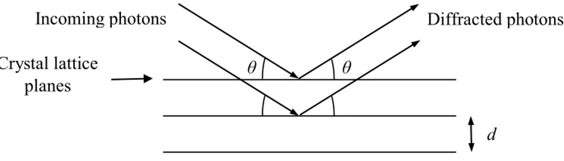
Figure 1-14 – Diffraction in Bragg (reflection) geometry in perfect flat crystals
Figure 1-15 – Diffraction in Laue (transmission) geometry in perfect flat crystals
Incoming photons Diffracted photons Crystal lattice
planes
d θ
θ
Incoming photons Diffracted photons
d
26
Laue lenses of modern design have the shape of a spherical calotte with curvature radius R and focal length f ≈ R/2. Diffraction planes are perpendicular to the lens calotte. Then, a photon with direction parallel to the optical axis will be deviated by two times the Bragg angle and focused to the detector. The focal length of Laue lenses are rather large because of the small diffraction angle for high energy photons. The best geometry for placing the crystals in a Laue lens is the Archimedean spiral. With this geometry, the energy of photon focused by the lens changes smoothly from one crystal to the following. Anyway, the construction of lenses with this geometry is difficult because of technological problems. A lens composed of concentric rings is technologically more feasible. In this case, the energy of photon focused changes from ring to ring with a less-smooth transition.
Figure 1-16
Crystals disposed on a Laue lens calotte following the Archimedean spiral.
Figure 1-17
Sketch of a Laue lens. An X-ray beam parallel to the lens axis is focused onto the detector.
The energy range of X-rays a Laue lens can focus depends from the dimension of the lens, from its focal length, and from the diffraction planes. Then, a Laue lens can focus photons with energy between Emin and Emax
𝐸𝑚𝑖𝑛 = ℎ𝑐 2𝑑𝑠𝑖𝑛𝜃𝑚𝑎𝑥~ ℎ𝑐𝑓 𝑑𝑟𝑚𝑎𝑥 𝐸𝑚𝑎𝑥= ℎ𝑐 2𝑑𝑠𝑖𝑛𝜃𝑚𝑖𝑛~ ℎ𝑐𝑓 𝑑𝑟𝑚𝑖𝑛
where h is the Planck’s constant, c is the velocity of light, d is the interplanar distance of diffraction planes, 𝜃𝑚𝑖𝑛 and 𝜃𝑚𝑎𝑥 are the minimum and maximum Bragg’s angles in the lens, f is the focal length,
rmin and rmax are the minimum and maximum radius of the lens calotte. It is possible to notice that
photons of low energy are diffracted by the external part of the lens, while high energy photons are diffracted by the inner part.
X-rays Laue lens
27
The reflectivity of the lens strongly depends upon the passband for photon diffraction of the crystals composing the lens. A crystal with large passband diffracts a large portion of the incoming photons, while a crystal with narrow passband does not. For perfect crystals, the passband is the Darwin width, which is very narrow for high-energy photons. As an example, the Darwin width for diffraction of 150 keV photons by Si (111) planes is about 0.35 arcsec. The small passband of perfect crystals strongly hampers the possibility to diffract a large portion of the incident photons. Moreover, the diffraction efficiency of a perfect crystal in Laue geometry is limited to a maximum of 50 % (1.2.2 Perfect flat crystals). The passband for photon diffraction can be enlarged using mosaic (1.2.3 Mosaic crystals) or curved crystals (1.2.4 Curved Diffracting Planes (CDPs) crystals). The small misalignment between the crystallites composing mosaic crystals enlarges the passband for photon diffraction. Copper or germanium mosaic crystals have been employed to build the Laue lenses developed up to now. However, the diffraction efficiency of mosaic crystals is limited to 50 % because each crystallite is a perfect crystal, with diffraction efficiency limited to 50 %. Moreover, real mosaic crystals usually show a non-ideal distribution dominated by random errors induced by the production process. CDPs crystals are perfect crystals with bent lattice planes. They are usually produced by bending perfect straight crystals. CDPs crystals offer a continuum of diffracting angles to the incoming X-ray beam, thus increasing the passband for diffraction. Diffraction efficiency of CDPs crystals can approach 100 % because the continuous change in the incidence angle produced by the curvature prevents re-diffraction of diffracted photons. Moreover, a crystal can have more than one curvature along different directions. With this technique, it is possible to adapt the shape of the crystal to the lens calotte, turning each crystal in a small Laue lens. Focusing crystals can reduce the dimension of the diffraction spot on the detector. Moreover, focusing crystals can have any dimension, without increasing the dimension of the diffraction spot, which means large crystals can produce the same resolution of smaller ones. Therefore, a small number of focusing crystal is needed for building a Laue lens. The reduction of the number of crystals simplifies the technological feasibility of Laue lenses.
28
1.2 Crystals for diffractive optics
1.2.1
Generalities of crystals
The crystals for X-ray optics are usually made from flat monocrystalline blocks. The crystalline perfection is critical to obtain good performances. The best mono-crystals that the technology is now capable of producing are silicon or germanium crystals, whose growth techniques have been refined for applications in electronics. For this reason silicon or germanium crystals are usually employed as crystals for X-ray optics.
An ideal crystal is composed of an infinite spatial repetition of identical structural units. In a crystal two points which differ by a translation vector linear combination of the length of the sides of the structural unit have the same fundamental physical properties. This structure is shown schematically by means of a regular distribution of mathematical points, the set of these points is called lattice. It is possible to define the lattice with three vectors, a1 a2 a3, such that the arrangement of the
atoms in the crystal is the same when viewed at the point r or at each point r ', where
r’ = r + u1a1 + u2a2 + u3a3
where u1, u2 e u3 are arbitrary integers. The vectors ai are define as the lattice constants. The volume
built on these vectors is called lattice cell. Each lattice point contains one or more atoms: the position of the atoms defined by each lattice point forms the basis. Lattice and base define the crystal, as the basis indicates the positions occupied by different atoms in the cell and their type, while the reticle provides the information on the periodicity of the crystal. The fundamental characteristic of the crystals is their invariance, for appropriate translations and rotations, of their physical properties, such as the optical, chemical, electrical and elastic properties.
Figure 1-18
Silicon fundamental cell.
Figure 1-19
Fundamental cell of silicon view as two interpenetrating fcc.
The space group that identifies each type of crystal defines these degrees of freedom. Base and reticle are not uniquely defined, there are endless combinations equivalent to describe the same crystal. A cell is called primitive if it contains only one lattice point. For example, the lattice of silicon
29
is face-centered cubic (fcc: faced centered cubic). The base of silicon has two identical atoms in the coordinates (0,0,0) and (a/4, a/4, a/4), where a is the lattice constant (5.43 Å) and identifies the side of the conventional cubic cell (Figure 1-18). In silicon, it is not possible to choose a lattice so that the base contains only one atom. This crystalline structure can also be represented as two interpenetrating face-centered cubic lattices, where the base of the second is located at the point (a/4, a/4, a/4). This type of lattice is called a diamond lattice (Figure 1-19).
Directions and planes in the crystal lattice are defined by the Miller indices. A family of planes is determined by three integers lmn, said Miller indices, representing the vector perpendicular to the family of planes. The Miller indices in parentheses represent the plane, the Miller indices in square brackets represent the direction perpendicular to the plane. The crystallographic directions are fictitious lines that connect the atoms in the crystal, as atomic planes are fictitious planes connecting atoms. Depending on the density of atoms along the directions or planes, and depending on the types of bonds present, the physical properties of the directions and planes change:
Optical properties Chemical properties Electrical properties
Mechanical and elastic properties
The distance of the atoms from the first neighbors changes according to the plan considered. As the same the properties of the crystal vary.
It is preferable to use crystals as possible similar to the ideal model, i.e. a uniform overlap of atomic planes, free of lattice defects. It is useful to treat the parameters that describe how a crystalline wafer deviates from the ideal model. The main ones are:
• Miscut angle of axes: is the angle between the nominal crystallographic direction of the wafer and its actual crystallographic direction. It is caused by the error in the cutting process of the original ingot.
• TTV (Total Thickness Variation): measures the maximum variation in thickness of the wafer. It is the error on the wafer thickness.
• Bowl: measures the morphological radius of curvature
of the wafer. It is usually produced during the process of lapping.
• Planarity: measures the morphological deformation of the wafer which is not included in the curvature measured by the bow.
• Roughness: represents how much the wafer surface is irregular and jagged on a small scale.
Figure 1-20
Planes with various Miller indices in a cubic lattice.
Figure 1-21
30
1.2.2
Perfect flat crystals
Crystalline materials are usually produced as ingots where the lattice planes are perfect and flat. Pieces of these crystals are used as X-ray optical elements acting by Bragg diffraction. The reflectivity of diffractive optical systems strongly depends upon the passband for photon diffraction of the crystals composing the systems. A crystal with large passband diffracts a large portion of the incoming photons, while a crystal with narrow passband does not. For perfect crystals, the passband is very narrow for high-energy photons. As an example, the Darwin width for diffraction of 150 keV photons by Si (111) planes is about 0.35 arcsec. The small passband of perfect crystals strongly hampers the possibility to diffract a large portion of the incident photons. Moreover, the diffraction efficiency of a perfect crystal when the beam traverses the crystal (Laue geometry) is limited to a maximum of 50 %. Indeed, a photon has the same probability to undergo an odd or even number of reflections traversing the crystal, then the same probability to exit the crystal in the diffraction or transmission direction. The process is sketched below in Figure 1-22
Figure 1-22 – Diffraction in Laue geometry in a perfect crystal
The passband for photon diffraction can be enlarged using mosaic or curved crystals, which are described in in the following sections (1.2.3 Mosaic crystals, 1.2.4 Curved Diffracting Planes (CDPs) crystals).
1.2.3
Mosaic crystals
Mosaic crystals are crystals composed of an ensemble of small crystals (crystallites) nearly parallel to each other. Crystallites are slightly misaligned around a principal direction. The dispersion of misalignments is ideally represented by a Gaussian function
𝑊(∆) = 1 √2𝜋𝜂𝑒 (− ∆2𝜂22) Incoming photons θ θ ½ photons undergo an even number of reflections ½ photons undergo an odd number of reflections
31
where ∆ is the mean misalignment of crystallites around the principal direction, 𝜂 is the standard deviation of the distribution. The full width half maximum (FWHM) of the Gaussian distribution defines the dispersion of crystallites, this quantity is called mosaicity β = 2,35 𝜂. Crystallites are far smaller than the dimension of the crystal, thus producing a continuous distribution. Each crystallite diffracts photons at a different Bragg angle, then the energy band the entire crystal can diffract is enlarged (Figure 1-23). The mosaicity typically ranges from tens of arcsec to tens of arcmin. The diffraction efficiency of mosaic crystals can be derived as
𝐼𝑚𝑜𝑠𝑎𝑖𝑐
𝐼0 = 1
2(1 − 𝑒−2𝜎𝑇0)𝑒
−𝑐𝑜𝑠𝜃𝜇𝑇0
where 𝐼0 is the intensity of the incoming beam, 𝐼𝑚𝑜𝑠𝑎𝑖𝑐
the intensity of the diffracted beam, 𝜇 is the absorption coefficient of the material composing the crystal at the energy E, 𝑇0 is the crystal thickness and 𝜎 is a parameter dependent from the dimension of crystallites, from the Gaussian distribution of orientation of crystallites and from the energy of the incoming photons. The diffraction efficiency of mosaic crystals is limited to 50 % because each crystallite is a perfect crystal, with diffraction efficiency limited to 50 %. Then, the fraction of the beam absorbed has to be removed. Some mosaic copper crystals produced at ILL (Grenoble, France) have been tested at the LARIX laboratories at the University of Ferrara. The experimental reflectivity of the mosaic crystals approached 20%. Reflectivity 0,25 0,2 0,15 0,1 0,05 0 85 90 95 100 105 110 Energy (keV)
The energy passband of mosaic crystals depends upon the distribution of the orientation of crystallites. Although this distribution should be ideally Gaussian, real mosaic crystals usually show
Figure 1-23
A mosaic crystal is composed of an ensemble of microscopic perfect crystals slightly misaligned. An incoming X-ray beam will encounter a multitude of possible diffraction angles.
Figure 1-24
Experimental output for a mosaic copper crystal by diffraction through (220) planes.
32
a non-ideal distribution dominated by random errors induced by the production process. Indeed, this distribution is poorly reproducible for real crystals. Furthermore, the maximum reflectivity is attained for crystallites of infinitesimal dimension, a condition clearly non-achievable in real crystals. Indeed, the dimension of crystallites usually is between tens and hundreds of microns.
1.2.4
Curved Diffracting Planes (CDPs) crystals
Curved diffracting planes crystals (CDPs crystals) are perfect crystals with bent lattice planes. CDP crystals are usually produced by bending perfect straight crystals (even if there have been some attempts to produce Si1-xGex crystals with bulk CDP (Abrosimov, 2005). Therefore, they are less
influenced by the manufacturing process than mosaic crystals. CDPs crystals offer a continuum of diffracting angles to the incoming X-ray beam, thus increasing the passband for diffraction. The increase in passband is proportional to the curvature and to the traversed thickness. Moreover, diffraction efficiency of curved crystals is not limited to 50 % maximum. Indeed, the continuous change of the incidence angle induced by the curvature prevents re-diffraction inside the crystal (Figure 1-25). Thus, diffracted photons cannot be diffracted again, and they all exit the crystal in the diffraction direction. Therefore, the diffraction efficiency of a CDPs crystal can approach 100 % (Barriére N. G.-X., 2010).
Figure 1-25
Diffraction in Laue (transmission) geometry in CDP crystals
1.2.5
State of the art for CDPs crystals production
Various methods have been developed over time to fabricate CDPs crystals. The easiest method, and historically the first to be applied, has been to induce a deformation to a perfect crystal through mechanical means. For example, mechanically bent silicon crystals are used in the latest generation of synchrotrons as high efficiency monochromators. This method for bending the crystals requires the presence of a holder to keep the crystal bent. This means that a part of the crystal is covered by the holder, which may be disadvantageous when it is necessary to maximize the area of incidence of the beam on the crystal. Because of the size of the holder, it is also difficult to use the crystals in geometries more complex than those of a simple monochromator, as in the case of Laue lenses. The same weight of the holder can be problematic for astrophysical devices that need to be used in orbit. Another method to produce CDPs crystals is the application of a thermal gradient. This technique allows to obtain a uniformly spherical profile of excellent quality. However, this method becomes difficult to apply when it is necessary to obtain a deformation profile different than a sphere, especially for large samples. Maintaining the temperature gradient requires a considerable expenditure of energy that is not always available, for example in equipment that must work in space.
Incident photons
θ θ ’
θ ’
33
A method to grow crystalline blocks with lattice planes inherently curved is to use an alloy of Silicon - Germanium in which there is a concentration gradient of the two materials along the growth axis (Abrosimov, 2005). The increase in concentration of germanium deforms the silicon lattice, producing a spherical deformation of the crystallographic planes perpendicular to the axis of growth. Since the concentration of germanium remains small in the whole crystal, the curvature is approximately proportional to the concentration of germanium ∇𝐶𝐺𝑒~𝜀/𝑅, where ∇𝐶𝐺𝑒 is the concentration gradient of germanium, ε is a constant, and R is the radius of curvature of the lattice planes. If we consider a spherical curvature, the concentration gradient of germanium can be put in relation to the range of possible diffraction angles α provided by the curvature of the crystal ∇𝐶𝐺𝑒~𝜀𝛼/𝑡 where t is the thickness of the sample. To produce crystals with a uniform bending a
great stability of the concentration gradient along the growth axis of the ingot is required. However, the presence of two materials with different lattice parameters within the same crystal leads to the formation of a high number of lattice imperfections, which results in a poor reproducibility of samples produced, and in most cases lowers the diffraction efficiency to the levels of crystal mosaic (Figure 1-26). Moreover, the manufacturing process is not simple to implement for the production of crystals in large quantities.
Figure 1-26
Left: design of a SiGe sample with size (15mm × 15mm × 30mm) analyzed at ILL (Grenoble, France) using a beam size of 7.6mm × 1.7mm and with a divergence of 2 arcsec, with photon energy 517 keV. The sample was analyzed in 6 points (red rectangles), through the thickness of 30 mm, the diffraction occurs on the planes (111). Right: the diffraction efficiency measured in the six points is analyzed as a function of the opening angle measured in the same points (using the FWHM of the rocking curves). In all cases, the diffraction efficiency was about 50%, and the angular aperture varies considerably between one point and another. The images and data are taken from (Barriére N. v., 2007).
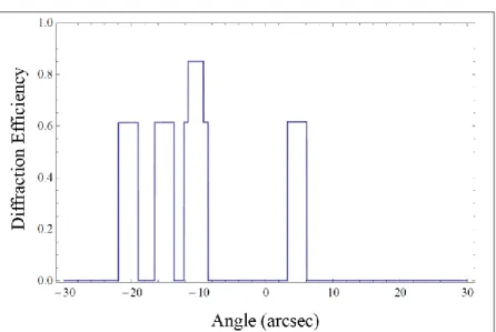
Recently, it was proved that grooving the surface of a silicon crystal leads to a plastic deformation of the entire crystal (3.3 The indentation method and our crystals), which causes a permanent bend of the same (Figure 1-27). This method is particularly interesting because it is not necessary to apply external forces to maintain the curvature. If the indentations are periodic, it is possible to obtain extremely uniform cylindrical or spherical curvatures, depending on the geometry with which the grooves are manufactured. Crystals of this type have shown a nearly-ideal diffraction efficiency, and a comparable angular aperture (Figure 1-28).
34
A last method still under study to produce curved crystals is to deposit a tensile film on the surface of a crystal to deform the entire structure. It is possible to apply this method by the deposition of a crystalline layer of material, or by the deposition of an amorphous layer. In the first case (heteroepitaxial growth), the deposited material grows into a crystalline structure with lattice parameter different from the crystalline structure of the substrate. At the interface between the two materials the different lattice parameters deform to match each other. This process results in a surface tension able to deform the entire crystal. In this case, one tries to minimize the number of dislocations at the interface that cause a relaxation in the material, thus maximizing the surface tension. For this reason, it is preferable to use materials with similar crystal structure and lattice parameters. In the second case (deposition of an amorphous) the surface tension is produced by the different index of thermal expansion of the two materials. The amorphous layer is deposited at high temperatures, under these conditions there is no surface tension. When the system is brought to room temperature, the thermal expansion undergone by the substrate and the film is different, thus generating a surface tension capable of imparting a deformation to the material. The study of these methods to obtain curved crystals with applications in the hard X-ray diffraction is still in its early stages, and little information is available regarding the diffraction efficiency reached and the uniformity of the curvature.
Figure 1-27
SEM image of the surface of a grooved silicon crystal.
Figure 1-28
Rocking curves in Laue diffraction of a silicon crystal bent by indentation, beam energy E = 150 keV, opening angle α = 14 arcsec, traversed thickness of 1 cm.