INDEX
1 - INTRODUCTION p. 3
2 - PCA-REPLICA EXPERIMENT p. 4
2.1 - PCA-Replica Experimental Facility p. 4
2.2 - PCA-Replica Fission Plate p. 10
2.3 - PCA-Replica Experimental Measures p. 15
3 - CROSS SECTION LIBRARIES AND NUCLEAR DATA p. 18
3.1 - BUGJEFF311.BOLIB Cross Section Library p. 18
3.2 - BUGENDF70.BOLIB Cross Section Library p. 18
3.3 - BUGLE-96 Cross Section Library p. 19
3.4 - IRDF-2002 Dosimeter Cross Sections p. 22
3.5 - U-235 Fission Neutron Spectra p. 30
4 - TRANSPORT CALCULATIONS p. 34
4.1 - Transport Calculation General Features p. 34
4.2 - PCA-Replica Fission Neutron Source p. 43
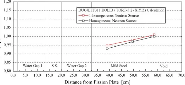
4.2.1 - Inhomogeneous Neutron Source p. 43
4.2.2 - Homogeneous Neutron Source p. 43
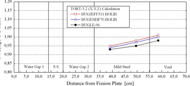
5 - DISCUSSION OF THE RESULTS p. 45
5.1 - Dosimetric Results p. 45
5.2 - Spectral Results p. 68
6 - CONCLUSION p. 79
REFERENCES p. 80
APPENDIX A Neutron Spectra Calculated along the Horizontal Axis Z
Using BUGJEFF311.BOLIB p. 83
APPENDIX B Neutron Spectra Calculated along the Horizontal Axis Z
Using BUGENDF70.BOLIB p. 95
APPENDIX C Neutron Spectra Calculated along the Horizontal Axis Z
Validation of the BUGJEFF311.BOLIB, BUGENDF70.BOLIB
and BUGLE-96 Cross Section Libraries on the PCA-Replica
(Water/Iron) Neutron Shielding Benchmark Experiment
Massimo PESCARINI, Roberto ORSI, Manuela FRISONI July 2014
1 - INTRODUCTION
The ENEA-Bologna Nuclear Data Group generated two broad-group coupled (47 n + 20 γ) working cross section libraries in FIDO-ANISN /1/ format, named BUGJEFF311.BOLIB /2/ and BUGENDF70.BOLIB /3/ and respectively based on the OECD-NEADB JEFF-3.1.1 /4/ (see also /5/) and US ENDF/B-VII.0 /6/ evaluated nuclear data libraries. The same neutron and photon energy group structure of the ORNL BUGLE-96 /7/ (ENDF/B-VI.3 /8/ evaluated nuclear data) working cross section library were adopted together with the same data format and processing methodology. All these ENEA-Bologna and ORNL libraries were specifically conceived for LWR shielding and pressure vessel dosimetry applications and contain problem-dependent parameterized sets of self-shielded cross sections specifically prepared for BWR and PWR applications. It was considered a meaningful test to validate the two ENEA-Bologna libraries and the ORNL library on the PCA-Replica /9/ (see also /10/) water/iron (H2O/Fe) engineering neutron shielding benchmark experiment that reproduces the ex-core radial geometry of a PWR and is included in the SINBAD /11/ (see also /12/) international database of reactor shielding benchmark experiments. PCA-Replica is particularly fit to test the cited working libraries since it was specifically conceived to check the calculated fast neutron fluxes in a PWR mild steel pressure vessel simulator. The results obtained with the BUGLE-96 library represent a reliable reference comparison because this library was widely and successfully used all over the world in the previously cited applications since 1996. The three cited libraries were alternatively used in fixed source transport calculations performed in Cartesian (X,Y,Z) geometry with the TORT-3.2 /13/ three-dimensional (3D) discrete ordinates (SN) code, included in the ORNL DOORS /14/ system of deterministic transport codes.
The neutron dosimeter cross sections used in the calculations were processed (see /15/) from the IAEA IRDF-2002 /16/ reactor dosimetry file. The ENEA-Bologna programs ADEFTA-4.1 /17/ and BOT3P-5.3 /18/ (see also /19/, /20/ and /21/) were respectively employed for the calculation of the isotopic atomic densities and for the automatic generation of the spatial mesh grid of the geometrical model. The calculated dosimetric and spectral integral results were compared with the corresponding experimental data, obtained using threshold activation dosimeters (Rh-103(n,n')Rh-103m, In-115(n,n')In-115m and S-32(n,p)P-32) for the dosimetric data and spherical hydrogen-filled proportional counters (type SP-2) together with a spherical organic liquid (NE213) scintillator for the spectral data.
2 - PCA-REPLICA EXPERIMENT
2.1 - PCA-Replica Experimental Facility
The PCA-Replica 12/13 low-flux engineering neutron shielding experiment /9//10/ (Winfrith, UK, 1984) is a water/iron (H2O/Fe) benchmark experiment including two water layers alternated with a PWR thermal shield (TS) simulator and a PWR pressure vessel (RPV) simulator. The PCA-Replica experimental facility (see FIGs. 2.1 and 2.2) duplicated exactly the ex-core radial geometry of the ORNL PCA (Poo1 Critical Assembly) /22/ similar experiment (Oak Ridge, US, 1981), simulating the ex-core radial geometry of a PWR. In particular PCA-Replica reproduced (see FIG. 2.3) the 12/13 configuration of the PCA experiment with a layer of water of about 12 cm between the core and the thermal shield simulator and a layer of water of about 13 cm between the thermal shield simulator and the pressure vessel simulator. An important feature differentiated the two experiments: the low-flux reactor neutron source of the PCA experiment was replaced in the PCA-Replica experiment with a neutron source emitted by a thin fission plate containing highly enriched uranium with a rectangular cross-sectional area identical to that of the PCA reactor source. It is underlined that this simpler source configuration of the PCA-Replica experiment could more easily be calibrated with a high degree of accuracy, reducing in this way a possible cause of the in-vessel neutron flux underpredictions noted in transport analyses dedicated to the PCA experiment, despite the extensive work addressed to obtain an accurate calibration /23/.
As previously cited, the source of neutrons in the PCA-Replica experiment was a rectangular fission plate irradiated (see FIGs. 2.2 and 2.3) by the NESTOR reactor (30 kW at the maximum power) through a graphite thermal column (total thickness = 43.91 cm), in the ASPIS shielding facility (see FIG. 2.2). The thin fission plate (with dimensions 63.5 × 40.2 × 0.6 cm) was made (see TAB. 2.1) of highly enriched uranium (93.0 w% in U-235) alloyed with aluminium. Beyond the fission plate, the Replica shielding array was arranged (see FIG. 2.2) in a large parallelepiped steel tank (square section; side 180.0 cm) filled with water and surrounded by a thick concrete shield. After the first water gap (12.1 cm thick) there was (see FIG. 2.3) the stainless steel thermal shield simulator and the second water gap (12.7 cm thick). Then the mild steel RPV simulator was located and tightly connected with a void box made of a thin layer of aluminium, simulating the air cavity between the RPV and the biological shield in a real PWR.
The fission plate (0.6 cm thick), the TS (5.9 cm thick), the RPV (thickness T = 22.5 cm) and the void box (29.58 cm thick) were perfectly orthogonally aligned and centred along the imaginary line Z (horizontal or nuclear axis) passing through the centroid of the fission plate (see FIGs. 2.3 and 2.6).
Along the horizontal nuclear axis Z, threshold activation neutron dosimeters and neutron spectrometers were located in all or in part of the ten measure spatial positions and gave respectively the dosimetric and spectral experimental results.
The dimensions and materials of the PCA-Replica 12/13 configuration are reported in TAB. 2.1 (derived from TAB. 2 of reference /9/) in 18 zones, along the horizontal nuclear axis Z. The material composition of the PCA-Replica experiment is shown in TAB. 2.2 (derived from TAB. 3 of reference /9/).
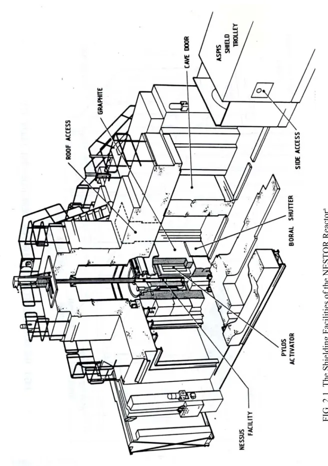
FIG. 2.1 The Shield
ing Facil
ities of the NESTOR Reactor
a . ( a ) Fig ur e deri ve d fr om FI G. 2 o f re fere nce / 9/.
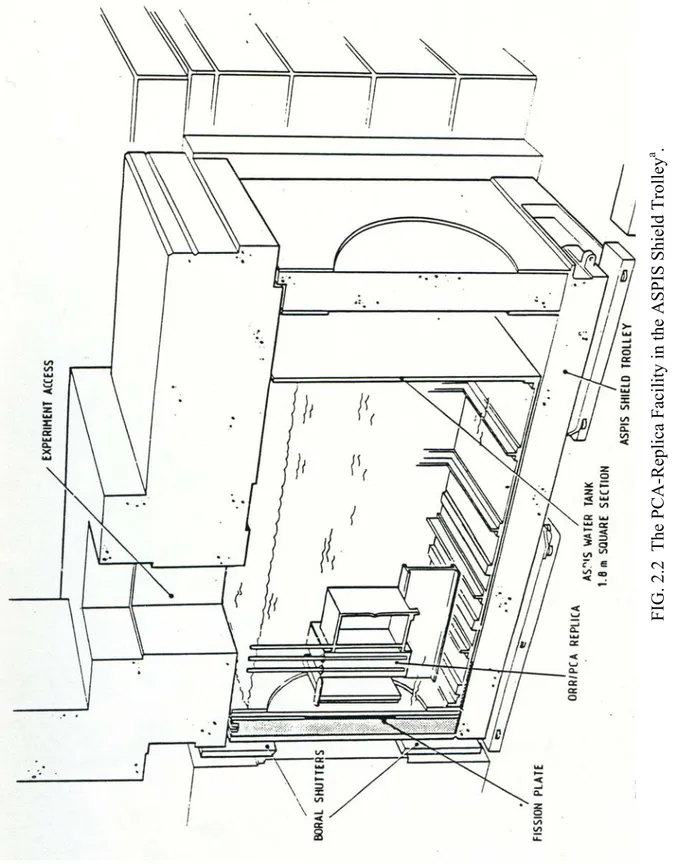
FIG. 2.2 The PCA-Replica Facility in the ASPIS Shield Trolley a . ( a ) Fig ur e derive d fr om F IG. 3 of ref erence /9/.
FIG. 2.3
PCA-Replica - Layout of the 12/13 Configuration a.
MATERIAL/ZONE NUMBER Graphite: 1, 5. Aluminium: 2, 4, 7, 9, 10, 15, 17. Void (Air): 3, 6, 16. Alloy Fuel (Fission Plate): 8. Water: 11, 13, 18. Stainless Steel: 12. Mild Steel: 14, 20, 21. Concrete: 19.
TAB. 2.1
PCA-Replica - Dimensions and Materials.
Zone Material Section Dimensions [cm]
1 Carbon Square 119 Side
2 Aluminium Square 119 Side
3 Void Square 185 Side
4 Aluminium Circular 56.06 Radius
5 Carbon Square 180 Side
6 Void Square 180 Side
7 Aluminium Rectangular 68.5 × 47.5
8 Fuel Rectangular 63.5 × 40.2
9 Aluminium Rectangular 68.5 × 47.5
10 Aluminium Square 180 Side
11 Water Square 180 Side
12 Stainless Steel Square 68.5 Side
13 Water Square 180 Side
14 Mild Steel Square 68.5 Side 15 Aluminium Square 60 Side
16 Void Square 59.4 Side
17 Aluminium Square 60 Side
18 Water Square 180 Side
Notes:
(1) The sides of the trolley are nominally 2.54 cm of steel and outside this steel and the coupling stack zones 1 and 2 (see FIG. 2.3) there is concrete.
(2) The aluminium plate zone 10 (see FIG. 2.3) is attached to a 1.91 cm thick steel plate which forms the front of the large water tank housing the PCA-Replica equipment. There is a 55.88 cm radius hole cut through the plate as shown in FIG. 2.2.
(3) The Z axial dimension of zone 8 shown in FIG. 2.3, 0.6 cm, is set to allow for four layers of alloy fuel each 0.1016 cm thick. The alloy fuel density is 3.257 g × cm-3 and to allow for the clearance gaps this should be reduced to 2.206 g × cm-3.
TAB. 2.2
PCA-Replica - Material Composition.
Material Material Density [g × cm-3] Element Weight [%] Atomic Density [atoms × cm-3] Graphite 1.65 C 100.0 8.276E+22 Aluminium Cladding 2.70 Al 100.0 6.029E+22 Alloy Fuel (a) 3.257 Al 80.0 5.818E+22
U-235 18.6 1.552E+21 U-238 1.4 1.154E+20 Water 1.0 H 11.19 6.688E+22 O 88.81 3.344E+22 Stainless Steel 7.88 C 0.017 6.721E+19 Si 0.44 7.438E+20 Mn 1.57 1.356E+21 P 0.025 3.832E+19 S 0.006 8.884E+18 Cr 18.4 1.688E+22 Ni 9.4 7.601E+21 Mo 0.37 1.831E+20 Ti 0.009 8.920E+18 Nb 0.014 7.154E+18 Cu 0.24 1.793E+20 Fe 69.509 5.909E+22 Mild Steel 7.835 C 0.22 8.646E+20 Mn 1.09 9.366E+20 P 0.01 1.524E+19 S 0.032 4.711E+19 Fe 98.648 8.338E+22 Concrete 2.3 Si 33.7 4.120E+22 Fe 1.4 8.609E+20 H 1.0 3.407E+22 O 52.9 1.135E+23 Al 3.4 4.327E+21 Ca 4.4 3.770E+21 Na 1.6 2.390E+21 K 1.6 1.405E+21
2.2 - PCA-Replica Fission Plate
The PCA-Replica experiment was driven by the neutron source emitted from a fission plate
coupled to the NESTOR reactor core via a graphite thermal column (see 2.1). The fission rate spatial distribution throughout the fission plate was required to provide a
source of adequate spatial resolution for neutronic transport calculations.
As reported on page 43 of reference /9/, the fission plate was constructed of 52 uranium aluminium alloy fuel strips of height 635 mm, width 30.48 mm and thickness 1.016 mm. The strips of density 3.257 g × cm-3 were 80% by weight of Al and 20% by weight of U enriched
to 93 w % in U-235. Sets of 4 fuel strips were laid on top of each other and 13 of these assemblies were placed side by side on a pitch of 30.92 mm to form the fuel structure of the fission plate. This structure (see zone 8 of FIG. 2.3) was enclosed in a thin aluminium envelope (see zones 7 and 9 of FIG. 2.3).
The fission plate detail is schematically shown in FIG. 2.4 (derived from FIG. A1 of reference /9/) whereas the fuel tablet arrangement in a fission plate element is described in FIG. 2.5 (derived from FIG. A11 of reference /9/).
The co-ordinate system used throughout the present analysis is the same as that reported in the FIG. 5 of reference /9/. The front of the fission plate is defined as the face closest to the core of the NESTOR reactor. The Z axis is from the NESTOR core through the centre of the rectangular fission plate, as shown in FIG. 2.6 (derived from FIG. A2 of reference /9/). The origin of the co-ordinate system (0.0, 0.0, 0.0) is positioned at the centre of the back face (see FIG. 2.6) of the thin aluminium envelope of the fission plate, as indicated also in FIG. 2.3 (derived from FIG. 5 of reference /9/). The X and Y axes together with the Z axis define respectively the horizontal and vertical planes across the fission plate.
Finally, the PCA-Replica neutron source strength spatial distribution (5×11 source mesh) per Watt of plate power in the 0.6 cm thick fission plate is reported in TAB. 2.3 (derived from TAB. A6 of reference /9/).
FIG. 2.4
PCA-Replica - Detail of the Fission Plate Fabricated in Aluminiuma,b.
(a) Figure derived from FIG. A1 of reference /9/.
(b) The numerical value of the alloy fuel density (3.256 g × cm-3) reported in the present figure is slightly
FIG. 2.5
PCA-Replica - Fuel Tablet Arrangement in a Fission Plate Elementa.
FIG. 2.6
PCA-Replica - Co-Ordinate Systema,b.
(a) Figure derived from FIG. A2 of reference /9/.
(b) The origin of the X, Y and Z axes in the reference system adopted is located in the centre of the back
TAB. 2.3
PCA-Replica - Neutron Source Strength Spatial Distribution (5×11 Mesh) in the 0.6 cm Thick Fission Platea.
[neutrons × cm-3 × s-1 × Plate Watt-1]
X-axis [cm] Y-axis
[cm]
-20.10 ÷ 12.10 -12.10 ÷ -4.10 -4.10 ÷ 4.10 4.10 ÷ 12.10 12.10 ÷ 20.10
-31.75 ÷ -26.32 4.424E+07 4.418E+07 4.495E+07 4.448E+07 4.560E+07
-26.32 ÷ -20.58 4.609E+07 4.518E+07 4.557E+07 4.535E+07 4.772E+07
-20.58 ÷ -15.44 4.885E+07 4.696E+07 4.744E+07 4.747E+07 5.040E+07
-15.44 ÷ -10.00 5.157E+07 4.885E+07 4.690E+07 4.989E+07 5.293E+07
-10.00 ÷ -3.33 5.393E+07 5.055E+07 5.160E+07 5.217E+07 5.505E+07
-3.33 ÷ 3.33 5.500E+07 5.135E+07 5.252E+07 5.332E+07 5.601E+07
3.33 ÷ 10.00 5.426E+07 5.078E+07 5.179E+07 5.264E+07 5.531E+07
10.00 ÷ 15.44 5.231E+07 4.927E+07 4.996E+07 5.069E+07 5.351E+07
15.44 ÷ 20.58 5.006E+07 4.764E+07 4.806E+07 4.855E+07 5.144E+07
20.58 ÷ 26.32 4.802E+07 4.642E+07 4.684E+07 4.699E+07 4.964E+07
26.32 ÷ 31.75 4.723E+07 4.670E+07 4.778E+07 4.756E+07 4.874E+07
Note: 1 Watt = 3.121E+10 × 2.437 [neutrons × s-1].
2.3 - PCA-Replica Experimental Measures
The threshold activation dosimeters used in the PCA-Replica 12/13 experiment along the
horizontal nuclear axis Z were Rh-103(n,n')Rh-103m, In-115(n,n')In-115m and S-32(n,p)P-32.
The Rh-103(n,n') dosimeters were located in the ten measure positions while the In-115(n,n') and S-32(n,p) dosimeters were used only in the following three measure positions: in the 1/4 T and 3/4 T positions in the RPV simulator and in the void box position.
The “as measured” experimental reaction rates of the dosimeters must be reduced (see page 10 of reference /9/) by 4% in the RPV and void box measure positions and by 2% in the measure positions located in the water gaps to correct for the presence of the NESTOR core neutron leakage background.
The reaction threshold energies for the Rh-103(n,n'), In-115(n,n') and S-32(n,p) dosimeters, in a light water material testing reactor (MTR) spectrum similar to that of the PCA-Replica experiment, are respectively 0.04, 0.34 and 0.95 MeV while the effective threshold energies are 0.69, 1.30 and 2.7 MeV (see /24/). Nevertheless, since the effective threshold is not a complete satisfactory parameter for the characterization of the energy dependent cross section functions, the present values give only a rough indication of the start of the response for the specific dosimeter. If one wishes to characterize the dosimeter response energy range more accurately, the energy range corresponding to 90% of the response and the median energy of the response should be taken into account. The median energy is defined such that, in the specific spectrum, the responses below and above this energy numerical value are equal. Secondly, the definition of the energy range corresponding to 90% of the total response of a dosimeter implies that 5% of the response is below the lower boundary and 5% above the upper boundary of this energy range. A synthesis of these data for the three dosimeters used in the PCA-Replica experiment is reported in TAB. 2.4 to give more specific detailed information addressed to obtain a more precise analysis in the comparison of the experimental and calculated dosimetric results.
TAB. 2.4
PCA-Replica - Dosimeter Parameters in a Light Water MTR Neutron Spectrum. (see /24/)
Dosimeter
Effective Energy Threshold
[MeV]
90% Response Energy Range
[MeV] Median Energy [MeV]
Rh-103(n,n') 0.69 0.53 - 5.4 1.9
In-115(n,n') 1.30 1.0 - 5.6 2.4
S-32(n,p) 2.70 2.2 - 7.4 3.9
In practice the experimental results coming from Rh-103(n,n') and In-115(n,n') (see /25/) correspond to neutron fluxes above about 1.0 MeV and the esperimental results from S-32(n,p) with neutron fluxes above about 3.0 MeV.
The spectral measures in the PCA-Replica 12/13 experiment were performed only in two positions (see FIG. 2.3): in the 1/4 T (Z = 39. 01 cm) position of the mild steel pressure vessel simulator and in the void box (Z = 58.61 cm) filled with air. As reported in reference /9/, two kinds of spectrometer were used. The spherical hydrogen-filled proportional counters employed were of type SP-2 of internal diameter 40.0 mm. Individual counters with gas fillings of approximately 0.5, 1.0, 3.0 and 10.0 atmospheres were used in combination, to cover the energy range from 50.0 keV to 1.2 MeV. The neutron fluxes between 1.0 and 10.0 MeV were determined with a spherical 3.5 ml organic liquid (NE213) scintillator.
The experimental neutron spectrum data taken in the two previously cited measure positions are shown in TAB. 2.5 (derived from TAB. 7 of reference /9/): the reported spectral data are given “as measured”, i.e. the NESTOR core neutron leakage background of 4% has not been removed.
The complete experimental details concerning the PCA-Replica 12/13 benchmark experiment are reported in reference /9/.
TAB. 2.5
PCA-Replica - Experimental Neutron Spectra as Measured in the 1/4 T RPV Position and in the Void Box Position.
Neutron Energy Group Boundaries
[MeV]
Lethargy Width
Neutron Flux Per Unit Lethargy / NESTOR Reactor Watt
Voided 1/4 T RPV Void Box
0.052 - 0.059 0.126 6.8 0.45 0.059 - 0.067 0.127 6.0 0.68 0.067 - 0.076 0.126 6.7 1.21 0.076 - 0.086 0.124 6.7 1.15 0.086 - 0.097 0.120 6.3 0.58 0.097 - 0.111 0.135 7.4 0.87 0.111 - 0.126 0.127 9.0 1.48 0.126 - 0.143 0.127 10.0 2.22 0.143 -0.162 0.125 9.0 1.62 0.162 - 0.183 0.122 10.0 1.92 0.183 - 0.207 0.123 9.2 1.60 0.207 - 0.235 0.127 10.3 1.49 0.235 - 0.266 0.124 11.7 2.22 0.266 - 0.302 0.127 14.0 3.13 0.302 - 0.342 0.124 17.0 3.31 0.342 - 0.388 0.126 16.0 2.99 0.388 - 0.439 0.123 13.7 1.88 0.439 - 0.498 0.126 16.2 2.33 0.498 - 0.564 0.124 19.0 2.74 0.564 - 0.639 0.125 23.9 4.12 0.639 - 0.724 0.125 20.3 3.19 0.724 - 0.821 0.126 17.1 1.75 0.821 - 0.930 0.125 15.7 1.93 0.930 - 1.054 0.125 15.5 1.69 1.054 - 1.194 0.125 15.3 1.53 1.194 - 1.353 0.125 13.7 1.16 1.353 - 1.534 0.126 13.8 0.94 1.534 - 1.738 0.125 13.3 0.78 1.738 - 1.969 0.125 11.9 0.61 1.969 - 2.231 0.125 11.7 0.46 2.231 - 2.528 0.125 11.2 0.35 2.528 - 2.865 0.125 9.2 0.27 2.865 - 3.246 0.125 6.9 0.18 3.246 - 3.679 0.125 4.4 0.13 3.679 - 4.169 0.125 4.8 0.10 4.169 - 4.724 0.125 5.0 0.09 4.724 - 5.353 0.125 4.2 0.09 5.353 - 6.065 0.125 3.5 0.07 6.065 - 6.873 0.125 2.2 0.06 6.873 - 7.788 0.125 1.5 0.03 7.788 - 8.825 0.125 1.1 0.02 8.825 - 10.0 0.125 0.2 --
3 - CROSS SECTION LIBRARIES AND NUCLEAR DATA
The group working cross section libraries (BUGJEFF311.BOLIB /2/, BUGENDF70.BOLIB /3/ and BUGLE-96 /7/) and the nuclear data (the IRDF-2002 /16/ derived reactor dosimetry cross sections /15/ and the JEFF-3.1.1, ENDF/B-VII.0 and ENDF/B-VI.3 U-235 fission neutron spectra in the BUGLE-96 neutron group structure) used in the present deterministic transport analysis are briefly described in this chapter. It is underlined that the ENEA-Bologna BUGJEFF311.BOLIB and BUGENDF70.BOLIB libraries adopted the same neutron (see TAB. 3.1) and photon (see TAB. 3.2) group structure of the ORNL BUGLE-96 library. 3.1 - BUGJEFF311.BOLIB Cross Section Library
BUGJEFF311.BOLIB /2/ is an ENEA-Bologna broad-group (47 neutron groups + 20 photon groups) coupled neutron and photon working cross section library in FIDO-ANISN format, generated in the same energy group structure of the ORNL BUGLE-96 /7/ similar library and based on the OECD-NEADB JEFF-3.1.1 /4/ /5/ evaluated nuclear data library. This library was obtained through problem-dependent cross section collapsing and self-shielding from the ENEA-Bologna VITJEFF311.BOLIB /26/ fine-group coupled neutron and photon pseudo-problem-independent library in AMPX format for nuclear fission applications. VITJEFF311.BOLIB adopts the same energy group structure (199 neutron groups + 42 photon groups) of the ORNL VITAMIN-B6 /7/ library and it is based on the Bondarenko /27/ (f-factor) neutron resonance self-shielding method.
BUGJEFF311.BOLIB, dedicated to LWR shielding and pressure vessel dosimetry applications, was generated with the ENEA-Bologna 2007 Revision /28/ of the ORNL SCAMPI /29/ nuclear data processing system, able to treat double precision data and freely released at OECD-NEADB and ORNL-RSICC.
The BUGJEFF311.BOLIB library was freely released at OECD-NEADB in 2011, assuming the designation NEA-1866 ZZ BUGJEFF311.BOLIB.
3.2 - BUGENDF70.BOLIB Cross Section Library
BUGENDF70.BOLIB /3/ is an ENEA-Bologna broad-group (47 neutron groups + 20 photon groups) coupled neutron and photon working cross section library in FIDO-ANISN format, generated in the same energy group structure of the ORNL BUGLE-96 /7/ similar library and based on the US ENDF/B-VII.0 /6/ evaluated nuclear data library. This library was obtained through problem-dependent cross section collapsing and self-shielding from the ENEA-Bologna VITENDF70.BOLIB /30/ fine-group coupled neutron and photon pseudo-problem-independent library in AMPX format for nuclear fission applications. VITENDF70.BOLIB adopts the same energy group structure (199 neutron groups + 42 photon groups) of the ORNL VITAMIN-B6 /7/ library and it is based on the Bondarenko /27/ (f-factor) neutron resonance self-shielding method.
BUGENDF70.BOLIB, dedicated to LWR shielding and pressure vessel dosimetry applications, was generated with the ENEA-Bologna 2007 Revision /28/ of the ORNL SCAMPI /29/ nuclear data processing system, able to treat double precision data and freely released at OECD-NEADB and ORNL-RSICC.
The BUGENDF70.BOLIB library was freely released at OECD-NEADB in 2013, assuming the designation NEA-1872 ZZ BUGENDF70.BOLIB.
3.3 - BUGLE-96 Cross Section Library
BUGLE-96 /7/ is an ORNL broad-group (47 neutron groups + 20 photon groups) coupled neutron and photon working cross section library in FIDO-ANISN format, based on the US ENDF/B-VI.3 /8/ evaluated nuclear data library. BUGLE-96 was obtained through problem-dependent cross section collapsing and self-shielding from the ORNL VITAMIN-B6 /7/ fine-group (199 neutron fine-groups + 42 photon fine-groups) coupled neutron and photon pseudo-problem-independent library in AMPX format for nuclear fission applications. VITAMIN-B6 is based on the Bondarenko /27/ (f-factor) neutron resonance self-shielding method.
BUGLE-96, dedicated to LWR shielding and pressure vessel dosimetry applications, was generated with the ORNL SCAMPI /29/ nuclear data processing system and was freely
released to OECD-NEADB in 1996 where assumed the designation DLC-0185 ZZ BUGLE-96. It is underlined that BUGLE-96, together with the mother library
VITAMIN-B6, became reference standards (see /31/, ANSI/ANS-6.1.2-1999 (R2009)) as multi-group libraries for shielding applications and they were successfully used all over the world.
TAB. 3.1
Neutron Group Energy and Lethargy Boundaries for the BUGLE-96 Library.
Group Upper Energy Upper Lethargy [eV] 1 1.7332E+07 -5.4997E-01 2 1.4191E+07 -3.5002E-01 3 1.2214E+07 -2.0000E-01 4 1.0000E+07 0. 5 8.6071E+06 1.5000E-01 6 7.4082E+06 3.0000E-01 7 6.0653E+06 5.0000E-01 8 4.9659E+06 7.0000E-01 9 3.6788E+06 1.0000E-00 10 3.0119E+06 1.2000E+00 11 2.7253E+06 1.3000E+00 12 2.4660E+06 1.4000E+00 13 2.3653E+06 1.4417E+00 14 2.3457E+06 1.4500E+00 15 2.2313E+06 1.5000E+00 16 1.9205E+06 1.6500E+00 17 1.6530E+06 1.8000E+00 18 1.3534E+06 2.0000E+00 19 1.0026E+06 2.3000E+00 20 8.2085E+05 2.5000E+00 21 7.4274E+05 2.6000E+00 22 6.0810E+05 2.8000E+00 23 4.9787E+05 3.0000E+00 24 3.6883E+05 3.3000E+00 25 2.9721E+05 3.5159E+00 26 1.8316E+05 4.0000E+00 27 1.1109E+05 4.5000E+00 28 6.7379E+04 5.0000E+00 29 4.0868E+04 5.5000E+00 30 3.1828E+04 5.7500E+00 31 2.6058E+04 5.9500E+00 32 2.4176E+04 6.0250E+00 33 2.1875E+04 6.1250E+00 34 1.5034E+04 6.5000E+00 35 7.1017E+03 7.2500E+00 36 3.3546E+03 8.0000E+00 37 1.5846E+03 8.7500E+00 38 4.5400E+02 1.0000E+01 39 2.1445E+02 1.0750E+01 40 1.0130E+02 1.1500E+01 41 3.7266E+01 1.2500E+01 42 1.0677E+01 1.3750E+01 43 5.0435E+00 1.4500E+01 44 1.8554E+00 1.5500E+01 45 8.7643E-01 1.6250E+01 46 4.1399E-01 1.7000E+01 47 1.0000E-01 1.8421E+01 1.0000E-05 2.7631E+01
TAB. 3.2
Photon Group Energy Boundaries for the BUGLE-96 Library.
Group Upper Energy [eV] 1 1.4000E+07 2 1.0000E+07 3 8.0000E+06 4 7.0000E+06 5 6.0000E+06 6 5.0000E+06 7 4.0000E+06 8 3.0000E+06 9 2.0000E+06 10 1.5000E+06 11 1.0000E+06 12 8.0000E+05 13 7.0000E+05 14 6.0000E+05 15 4.0000E+05 16 2.0000E+05 17 1.0000E+05 18 6.0000E+04 19 3.0000E+04 20 2.0000E+04 1.0000E+04
3.4 - IRDF-2002 Dosimeter Cross Sections
The threshold activation dosimeter cross sections used in the transport calculations were all derived (see /15/) from the IAEA International Reactor Dosimetry File 2002 /16/ (IRDF-2002). A major objective of this data development project was to prepare and distribute a standardized, updated and tested reactor dosimetry cross section library accompanied by uncertainty information for use in service life assessments of nuclear power reactors.
In particular the Rh-103(n,n')Rh-103m, In-115(n,n')In-115m and S-32(n,p)P-32 dosimeter cross sections needed in the PCA-Replica transport analyses with the ENEA-Bologna BUGJEFF311.BOLIB /2/ and BUGENDF70.BOLIB /3/ cross section libraries were taken respectively from the corresponding library packages. These data were derived from the IRDF-2002 set of point-wise dosimetry cross sections through proper data processing with the GROUPIE program of the PREPRO 2007 /32/ nuclear data processing system into the BUGJEFF311.BOLIB and BUGENDF70.BOLIB 47-group neutron energy structure, identical to that of the ORNL BUGLE-96 /7/ cross section library. These dosimeter cross sections were obtained (see /15/) using two cross section weightings (“flat weighting” and “1/4 T RPV weighting”) in the 199-group neutron energy structure of the ORNL VITAMIN-B6 /7/ library, adopted by the fine-group mother libraries of BUGJEFF311.BOLIB and BUGENDF70.BOLIB, i.e. by VITJEFF311.BOLIB /26/ and VITENDF70.BOLIB /30/ respectively. In particular the 1/4 T RPV neutron weighting spectra were obtained at the one-quarter thickness (T) position of the pressure vessel of a typical PWR, through problem-dependent one-dimensional transport calculations using alternatively the VITJEFF311.BOLIB (see TAB. 3.4 of reference /2/) and VITENDF70.BOLIB (see TAB. 3.4 of reference /3/) libraries. Concerning the IRDF-2002 1/4 T RPV weighting neutron dosimeter cross sections used in the transport calculations with BUGLE-96, they were obtained for the present transport analysis with the same calculation procedure previously described, using the 1/4 T RPV neutron weighting spectrum (see TAB. 3.4 of reference /7/) calculated at ORNL with the VITAMIN-B6 fine-group mother library of BUGLE-96.
It is underlined that, for the same specific dosimeter, the group numerical values of each flat weighting cross section set in the BUGLE-96 47-group neutron energy structure are obviously identical for all the three BUGJEFF311.BOLIB, BUGENDF70.BOLIB and BUGLE-96 libraries used in the transport calculations.
The flat weighting 47-group cross sections for the three Rh-103(n,n')Rh-103m, In-115(n,n')In-115m and S-32(n,p)P-32 dosimeters, used together with all the three cited
working cross section libraries, are reported in TAB. 3.3 and their corresponding graphical representations are respectively shown in FIGs. 3.1, 3.2 and 3.3.
The 1/4 T RPV weighting 47-group cross sections for the three Rh-103(n,n')Rh-103m, In-115(n,n')In-115m and S-32(n,p)P-32 dosimeters are respectively reported in the TABs. 3.4, 3.5 and 3.6, respectively for the BUGJEFF311.BOLIB, BUGENDF70.BOLIB and BUGLE-96 cross section libraries.
FIG. 3.1
IRDF-2002 Flat Weighting Rh-103(n,n')Rh-103m Dosimeter Cross Sections in the BUGLE-96 47-Group Neutron Energy Structure.
FIG. 3.2
IRDF-2002 Flat Weighting In-115(n,n')In-115m Dosimeter Cross Sections in the BUGLE-96 47-Group Neutron Energy Structure.
FIG. 3.3
IRDF-2002 Flat Weighting S-32(n,p)P-32 Dosimeter Cross Sections in the BUGLE-96 47-Group Neutron Energy Structure.
TAB. 3.3
IRDF-2002 Flat Weighting Neutron Dosimeter Cross Sections [barns] Used in the TORT-3.2 Calculations with BUGJEFF311.BOLIB, BUGENDF70.BOLIB and BUGLE-96.
Group Upper Energy [MeV] Rh-103(n,n') In-115(n,n') (n,p) S-32
1 1.7332E+01 2.3466E-01 5.8133E-02 1.7639E-01
2 1.4191E+01 3.8742E-01 9.1680E-02 3.0787E-01
3 1.2214E+01 8.1816E-01 2.0239E-01 3.8051E-01
4 1.0000E+01 1.2190E+00 2.7381E-01 3.3979E-01
5 8.6071E+00 1.2753E+00 3.0859E-01 3.2202E-01
6 7.4082E+00 1.2305E+00 3.3417E-01 3.1380E-01
7 6.0653E+00 1.1732E+00 3.3897E-01 2.4629E-01
8 4.9659E+00 1.1091E+00 3.2538E-01 2.7592E-01
9 3.6788E+00 1.0370E+00 3.3341E-01 1.9108E-01
10 3.0119E+00 9.8735E-01 3.5259E-01 1.0053E-01
11 2.7253E+00 9.5185E-01 3.5385E-01 6.8686E-02
12 2.4660E+00 9.2536E-01 3.4311E-01 7.2417E-02
13 2.3653E+00 9.1570E-01 3.3654E-01 6.6472E-02
14 2.3457E+00 9.0494E-01 3.2759E-01 6.1245E-02
15 2.2313E+00 8.6764E-01 2.9012E-01 2.1377E-02
16 1.9205E+00 8.0955E-01 2.3022E-01 4.1502E-03
17 1.6530E+00 7.4452E-01 1.7096E-01 5.9998E-04
18 1.3534E+00 6.6193E-01 1.0336E-01 6.0917E-05
19 1.0026E+00 5.8044E-01 4.9401E-02 1.6785E-06
20 8.2085E-01 4.9269E-01 2.7891E-02 0.
21 7.4274E-01 3.3867E-01 1.5489E-02 0.
22 6.0810E-01 1.9319E-01 6.3893E-03 0.
23 4.9787E-01 1.3801E-01 2.2558E-03 0.
24 3.6883E-01 1.0374E-01 1.6310E-04 0.
25 2.9721E-01 6.6383E-02 0. 0. 26 1.8316E-01 2.3291E-02 0. 0. 27 1.1109E-01 5.8219E-03 0. 0. 28 6.7379E-02 1.6581E-03 0. 0. 29 4.0868E-02 3.4572E-06 0. 0. 30 3.1828E-02 0. 0. 0. 31 2.6058E-02 0. 0. 0. 32 2.4176E-02 0. 0. 0. 33 2.1875E-02 0. 0. 0. 34 1.5034E-02 0. 0. 0. 35 7.1017E-03 0. 0. 0. 36 3.3546E-03 0. 0. 0. 37 1.5846E-03 0. 0. 0. 38 4.5400E-04 0. 0. 0. 39 2.1445E-04 0. 0. 0. 40 1.0130E-04 0. 0. 0. 41 3.7266E-05 0. 0. 0. 42 1.0677E-05 0. 0. 0. 43 5.0435E-06 0. 0. 0. 44 1.8554E-06 0. 0. 0. 45 8.7643E-07 0. 0. 0. 46 4.1399E-07 0. 0. 0. 47 1.0000E-07 0. 0. 0 1.0000E-11
TAB. 3.4
IRDF-2002 1/4 T RPV Weighting Neutron Dosimeter Cross Sections [barns] Used in the TORT-3.2 Calculations with the BUGJEFF311.BOLIB Library.
Group Upper Energy [MeV] Rh-103(n,n') In-115(n,n') (n,p) S-32
1 1.7332E+01 2.4762E-01 5.9192E-02 1.9546E-01
2 1.4191E+01 4.0937E-01 9.8480E-02 3.1934E-01
3 1.2214E+01 8.8683E-01 2.1539E-01 3.7876E-01
4 1.0000E+01 1.2278E+00 2.7598E-01 3.3761E-01
5 8.6071E+00 1.2744E+00 3.1011E-01 3.2276E-01
6 7.4082E+00 1.2262E+00 3.3546E-01 3.1147E-01
7 6.0653E+00 1.1713E+00 3.3869E-01 2.4085E-01
8 4.9659E+00 1.1079E+00 3.2516E-01 2.7606E-01
9 3.6788E+00 1.0344E+00 3.3444E-01 1.8725E-01
10 3.0119E+00 9.8700E-01 3.5268E-01 1.0010E-01
11 2.7253E+00 9.5196E-01 3.5387E-01 6.8656E-02
12 2.4660E+00 9.2492E-01 3.4283E-01 7.2333E-02
13 2.3653E+00 9.1570E-01 3.3654E-01 6.6472E-02
14 2.3457E+00 9.0468E-01 3.2736E-01 6.1061E-02
15 2.2313E+00 8.6739E-01 2.8986E-01 2.1176E-02
16 1.9205E+00 8.0741E-01 2.2810E-01 3.8470E-03
17 1.6530E+00 7.4261E-01 1.6934E-01 5.7068E-04
18 1.3534E+00 6.5961E-01 1.0148E-01 5.6340E-05
19 1.0026E+00 5.7702E-01 4.7963E-02 1.2101E-06
20 8.2085E-01 4.9153E-01 2.7746E-02 0.
21 7.4274E-01 3.2977E-01 1.4938E-02 0.
22 6.0810E-01 1.9398E-01 6.4499E-03 0.
23 4.9787E-01 1.3615E-01 2.1316E-03 0.
24 3.6883E-01 1.0322E-01 1.5017E-04 0.
25 2.9721E-01 6.5599E-02 0. 0. 26 1.8316E-01 2.3237E-02 0. 0. 27 1.1109E-01 5.3946E-03 0. 0. 28 6.7379E-02 1.6350E-03 0. 0. 29 4.0868E-02 3.5663E-06 0. 0. 30 3.1828E-02 0. 0. 0. 31 2.6058E-02 0. 0. 0. 32 2.4176E-02 0. 0. 0. 33 2.1875E-02 0. 0. 0. 34 1.5034E-02 0. 0. 0. 35 7.1017E-03 0. 0. 0. 36 3.3546E-03 0. 0. 0. 37 1.5846E-03 0. 0. 0. 38 4.5400E-04 0. 0. 0. 39 2.1445E-04 0. 0. 0. 40 1.0130E-04 0. 0. 0. 41 3.7266E-05 0. 0. 0. 42 1.0677E-05 0. 0. 0. 43 5.0435E-06 0. 0. 0. 44 1.8554E-06 0. 0. 0. 45 8.7643E-07 0. 0. 0. 46 4.1399E-07 0. 0. 0. 47 1.0000E-07 0. 0. 0 1.0000E-11
TAB. 3.5
IRDF-2002 1/4 T RPV Weighting Neutron Dosimeter Cross Sections [barns] Used in the TORT-3.2 Calculations with the BUGENDF70.BOLIB Library.
Group Upper Energy [MeV] Rh-103(n,n') In-115(n,n') (n,p) S-32
1 1.7332E+01 2.4736E-01 5.9174E-02 1.9504E-01
2 1.4191E+01 4.0943E-01 9.8495E-02 3.1939E-01
3 1.2214E+01 8.8628E-01 2.1529E-01 3.7877E-01
4 1.0000E+01 1.2280E+00 2.7602E-01 3.3756E-01
5 8.6071E+00 1.2743E+00 3.1014E-01 3.2279E-01
6 7.4082E+00 1.2259E+00 3.3553E-01 3.1134E-01
7 6.0653E+00 1.1713E+00 3.3870E-01 2.4087E-01
8 4.9659E+00 1.1080E+00 3.2519E-01 2.7597E-01
9 3.6788E+00 1.0340E+00 3.3463E-01 1.8679E-01
10 3.0119E+00 9.8681E-01 3.5274E-01 9.9856E-02
11 2.7253E+00 9.5184E-01 3.5384E-01 6.8690E-02
12 2.4660E+00 9.2505E-01 3.4291E-01 7.2357E-02
13 2.3653E+00 9.1570E-01 3.3654E-01 6.6472E-02
14 2.3457E+00 9.0476E-01 3.2744E-01 6.1120E-02
15 2.2313E+00 8.6750E-01 2.8997E-01 2.1288E-02
16 1.9205E+00 8.0709E-01 2.2780E-01 3.8128E-03
17 1.6530E+00 7.4285E-01 1.6955E-01 5.7288E-04
18 1.3534E+00 6.5898E-01 1.0098E-01 5.5136E-05
19 1.0026E+00 5.7853E-01 4.8555E-02 1.3091E-06
20 8.2085E-01 4.9180E-01 2.7780E-02 0.
21 7.4274E-01 3.2413E-01 1.4595E-02 0.
22 6.0810E-01 1.9458E-01 6.4916E-03 0.
23 4.9787E-01 1.3637E-01 2.1464E-03 0.
24 3.6883E-01 1.0321E-01 1.5024E-04 0.
25 2.9721E-01 6.5947E-02 0. 0. 26 1.8316E-01 2.3120E-02 0. 0. 27 1.1109E-01 5.3290E-03 0. 0. 28 6.7379E-02 1.6314E-03 0. 0. 29 4.0868E-02 3.5772E-06 0. 0. 30 3.1828E-02 0. 0. 0. 31 2.6058E-02 0. 0. 0. 32 2.4176E-02 0. 0. 0. 33 2.1875E-02 0. 0. 0. 34 1.5034E-02 0. 0. 0. 35 7.1017E-03 0. 0. 0. 36 3.3546E-03 0. 0. 0. 37 1.5846E-03 0. 0. 0. 38 4.5400E-04 0. 0. 0. 39 2.1445E-04 0. 0. 0. 40 1.0130E-04 0. 0. 0. 41 3.7266E-05 0. 0. 0. 42 1.0677E-05 0. 0. 0. 43 5.0435E-06 0. 0. 0. 44 1.8554E-06 0. 0. 0. 45 8.7643E-07 0. 0. 0. 46 4.1399E-07 0. 0. 0. 47 1.0000E-07 0. 0. 0. 1.0000E-11
TAB. 3.6
IRDF-2002 1/4 T RPV Weighting Neutron Dosimeter Cross Sections [barns] Used in the TORT-3.2 Calculations with the BUGLE-96 Library.
Group Upper Energy [MeV] Rh-103(n,n') In-115(n,n') (n,p) S-32
1 1.7332E+01 2.4772E-01 5.9202E-02 1.9559E-01
2 1.4191E+01 4.0865E-01 9.8250E-02 3.1902E-01
3 1.2214E+01 8.8555E-01 2.1510E-01 3.7870E-01
4 1.0000E+01 1.2278E+00 2.7598E-01 3.3761E-01
5 8.6071E+00 1.2744E+00 3.1003E-01 3.2271E-01
6 7.4082E+00 1.2258E+00 3.3556E-01 3.1129E-01
7 6.0653E+00 1.1715E+00 3.3873E-01 2.4137E-01
8 4.9659E+00 1.1082E+00 3.2521E-01 2.7623E-01
9 3.6788E+00 1.0339E+00 3.3469E-01 1.8660E-01
10 3.0119E+00 9.8682E-01 3.5273E-01 9.9863E-02
11 2.7253E+00 9.5186E-01 3.5385E-01 6.8684E-02
12 2.4660E+00 9.2505E-01 3.4291E-01 7.2357E-02
13 2.3653E+00 9.1570E-01 3.3654E-01 6.6472E-02
14 2.3457E+00 9.0478E-01 3.2745E-01 6.1132E-02
15 2.2313E+00 8.6752E-01 2.8999E-01 2.1297E-02
16 1.9205E+00 8.0707E-01 2.2777E-01 3.8088E-03
17 1.6530E+00 7.4286E-01 1.6956E-01 5.7312E-04
18 1.3534E+00 6.5890E-01 1.0091E-01 5.5073E-05
19 1.0026E+00 5.7861E-01 4.8582E-02 1.3126E-06
20 8.2085E-01 4.9185E-01 2.7786E-02 0.
21 7.4274E-01 3.2307E-01 1.4531E-02 0.
22 6.0810E-01 1.9477E-01 6.5054E-03 0.
23 4.9787E-01 1.3666E-01 2.1654E-03 0.
24 3.6883E-01 1.0314E-01 1.4947E-04 0.
25 2.9721E-01 6.5891E-02 0. 0. 26 1.8316E-01 2.3016E-02 0. 0. 27 1.1109E-01 5.3395E-03 0. 0. 28 6.7379E-02 1.6339E-03 0. 0. 29 4.0868E-02 3.5776E-06 0. 0. 30 3.1828E-02 0. 0. 0. 31 2.6058E-02 0. 0. 0. 32 2.4176E-02 0. 0. 0. 33 2.1875E-02 0. 0. 0. 34 1.5034E-02 0. 0. 0. 35 7.1017E-03 0. 0. 0. 36 3.3546E-03 0. 0. 0. 37 1.5846E-03 0. 0. 0. 38 4.5400E-04 0. 0. 0. 39 2.1445E-04 0. 0. 0. 40 1.0130E-04 0. 0. 0. 41 3.7266E-05 0. 0. 0. 42 1.0677E-05 0. 0. 0. 43 5.0435E-06 0. 0. 0. 44 1.8554E-06 0. 0. 0. 45 8.7643E-07 0. 0. 0. 46 4.1399E-07 0. 0. 0. 47 1.0000E-07 0. 0. 0 1.0000E-11
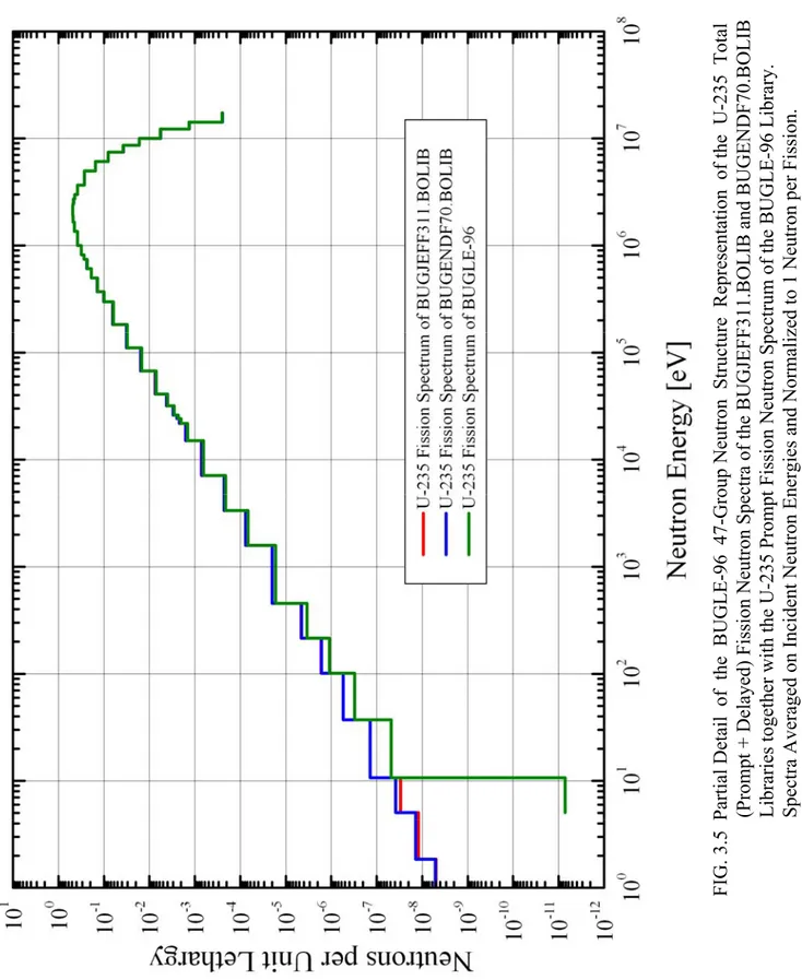
3.5 - U-235 Fission Neutron Spectra
The U-235 fission neutron spectra (χ) used to obtain the PCA-Replica neutron source in the fixed source transport calculations (see Chapter 4) are reported in TAB. 3.7.
It is underlined that, whereas the U-235 fission spectrum data included in the package of the ORNL BUGLE-96 /7/ library refer only to prompt neutrons, the U-235 fission spectrum data contained respectively in the packages of the ENEA-Bologna BUGJEFF311.BOLIB /2/ and BUGENDF70.BOLIB /3/ similar libraries are total fission spectra, i.e. they include the contributions of both prompt and delayed neutrons. This option was made available through the use of the ENEA-Bologna 2007 Revision /28/ of the ORNL SCAMPI /29/ nuclear data processing system, freely released at OECD-NEADB and ORNL-RSICC.
Graphical representations of the U-235 total fission neutron spectra (χ) for the BUGJEFF311.BOLIB and BUGENDF70.BOLIB libraries together with the U-235 prompt fission neutron spectrum (χ) for the BUGLE-96 library are reported in FIG. 3.4 and 3.5.
TAB. 3.7
Total or Prompt U-235 Fission Neutron Spectra (χ) Used in the TORT-3.2 Calculations Using the BUGJEFF311.BOLIB, BUGENDF70.BOLIB and BUGLE-96 Libraries
Group Upper Energy
[MeV] BUGJEFF311.BOLIBTotal (χ) U-235 Total (χ) U-235 BUGENDF70.BOLIB Prompt (χ) U-235BUGLE-96
1 1.7332E+01 4.9847E-05 4.9839E-05 5.0179E-05
2 1.4191E+01 2.0032E-04 2.0031E-04 2.0166E-04
3 1.2214E+01 1.1384E-03 1.1384E-03 1.1460E-03
4 1.0000E+01 2.5055E-03 2.5055E-03 2.5222E-03
5 8.6071E+00 5.6193E-03 5.6195E-03 5.6568E-03
6 7.4082E+00 1.6040E-02 1.6041E-02 1.6147E-02
7 6.0653E+00 3.0508E-02 3.0511E-02 3.0712E-02
8 4.9659E+00 7.9978E-02 7.9986E-02 8.0512E-02
9 3.6788E+00 7.6252E-02 7.6258E-02 7.6758E-02
10 3.0119E+00 4.3722E-02 4.3728E-02 4.4010E-02
11 2.7253E+00 4.6381E-02 4.6388E-02 4.6685E-02
12 2.4660E+00 1.9899E-02 1.9903E-02 2.0028E-02
13 2.3653E+00 4.0004E-03 4.0013E-03 4.0262E-03
14 2.3457E+00 2.4188E-02 2.4193E-02 2.4344E-02
15 2.2313E+00 7.3086E-02 7.3105E-02 7.3547E-02
16 1.9205E+00 7.1516E-02 7.1538E-02 7.1946E-02
17 1.6530E+00 8.9032E-02 8.9083E-02 8.9495E-02
18 1.3534E+00 1.1467E-01 1.1474E-01 1.1503E-01
19 1.0026E+00 6.2706E-02 6.2734E-02 6.2685E-02
20 8.2085E-01 2.7337E-02 2.7329E-02 2.7239E-02
21 7.4274E-01 4.7125E-02 4.7130E-02 4.6851E-02
22 6.0810E-01 3.8049E-02 3.8038E-02 3.7615E-02
23 4.9787E-01 4.2477E-02 4.2436E-02 4.1771E-02
24 3.6883E-01 2.1827E-02 2.1807E-02 2.1390E-02
25 2.9721E-01 3.0837E-02 3.0779E-02 3.0048E-02
26 1.8316E-01 1.5950E-02 1.5922E-02 1.5408E-02
27 1.1109E-01 7.7422E-03 7.7147E-03 7.4251E-03
28 6.7379E-02 3.7043E-03 3.6943E-03 3.5461E-03
29 4.0868E-02 1.0482E-03 1.0459E-03 9.9806E-04
30 3.1828E-02 6.0737E-04 6.0374E-04 5.6977E-04
31 2.6058E-02 1.8654E-04 1.8501E-04 1.7337E-04
32 2.4176E-02 2.1922E-04 2.1735E-04 2.0305E-04
33 2.1875E-02 5.9716E-04 5.8781E-04 5.4037E-04
34 1.5034E-02 5.3875E-04 5.3054E-04 4.8419E-04
35 7.1017E-03 1.7068E-04 1.7033E-04 1.5746E-04
36 3.3546E-03 5.7556E-05 5.7386E-05 5.1156E-05
37 1.5846E-03 2.4994E-05 2.4884E-05 2.0827E-05
38 4.5400E-04 3.4437E-06 3.4200E-06 2.5484E-06
39 2.1445E-04 1.2527E-06 1.2414E-06 8.2729E-07
40 1.0130E-04 5.5078E-07 5.4440E-07 3.0900E-07
41 3.7266E-05 1.7589E-07 1.7323E-07 5.9997E-08
42 1.0677E-05 2.2718E-08 2.9006E-08 5.4050E-12
43 5.0435E-06 1.2140E-08 1.3842E-08 0.
44 1.8554E-06 3.7279E-09 3.8754E-09 0.
45 8.7643E-07 1.7610E-09 1.7694E-09 0.
46 4.1399E-07 1.1957E-09 1.1790E-09 0.
47 1.0000E-07 3.8080E-10 3.7167E-10 0.
FIG. 3.4 BUGLE-96 47-Group Neutron Structure Repres
entation of the U-235 Total (Prompt + Delayed)
Fission Neutron Spectra of
the BUGJEFF311.BOLIB and BUGENDF
70.BOLIB Libraries together
with the U-235 Pr
ompt Fission Neutron Spectru
m of the BUGLE-96 Library.
Spectra Averaged on Incident
Neutron Energies and Normaliz
FIG. 3.5 Partial Detail of the BUGLE-96 47-Group Neut
ron Structure Representa
tion of the U-235 Total
(Prompt + Delayed) Fission
Neutron Spectra of the BUGJEF
F311.BOLIB a
nd BUGENDF70.BOLIB
Libraries together with the
U-235 Prompt Fission N
eutron Spectr
um of the B
UGLE-96 Library.
Spectra Averaged on Incident
Neutron Energies and Normaliz
4 - TRANSPORT CALCULATIONS
4.1 - Transport Calculation General Features
The whole PCA-Replica experimental array (see /9/ and 2.1) was reproduced with the TORT-3.2 /13/ three-dimensional (3D) discrete ordinates (SN) code included in the ORNL DOORS-3.2 /14/ system of deterministic codes.
The TORT-3.2 code was used on a personal computer (CPU: INTEL PENTIUM D 3.40 GHz, 3.10 GB of RAM) under Linux openSUSE 10.2 (i586) operating system with FORTRAN-77 compiler g77, version 3.3.5-38.
The ENEA-Bologna ADEFTA-4.1 /17/ program was employed in the calculation of the atomic densities of the isotopes involved in the compositional model on the basis of the atomic abundances reported in the BNL-NNDC database /33/ included in ADEFTA. This calculation was necessary since the atomic densities of the PCA-Replica experiment, indicated in the official material composition in TAB. 2.2 (derived from TAB. 3 of reference /9/), are given for natural element except for the two uranium isotopes U-235 and U-238.
The automatic generation of the spatial mesh grid and the graphical verification of the PCA-Replica benchmark experiment geometrical model for TORT-3.2 were performed through the ENEA-Bologna BOT3P-5.3 /18/ pre/post-processor system.
In all the calculations it was reproduced the whole three-dimensional PCA-Replica experimental array in the (X,Y,Z) Cartesian geometry in order to assure a proper detailed description of the spatial heterogeneity of the neutron source emitted by the fission plate. In particular it was described a parallelepiped geometry (whose dimensions were 185.08 ×
180.0 × 180.0 cm, respectively along the X, Y and Z axis) with a 65X×63Y×182Z fine spatial mesh grid, where Z was the horizontal nuclear axis (see FIGs. 2.3 and 2.6) where the dosimeter measure positions were located. Volumetric meshes with sides always inferior to 0.5 cm were described along the Z axis to obtain the best accuracy in the calculations.
The horizontal section (at Y = 0.0 cm) of the PCA-Replica compositional and geometrical model reproduced in all the TORT-3.2 (X,Y,Z) calculations is reported in FIG. 4.1 together with the dosimeter locations.
The ENEA-Bologna BUGJEFF311.BOLIB /2/ (JEFF-3.1.1 /4/ /5/ data) and BUGENDF70.BOLIB /3/ (ENDF/B-VII.0 /6/ data) working libraries were alternatively used in the transport calculations with TORT-3.2 together with the ORNL BUGLE-96 /7/ (ENDF/B-VI.3 /8/ data) working library assumed as a reliable standard library for the neutron dose and neutron spectrum calculated results. A brief description of each previously cited library is reported in Chapter 3 (see respectively 3.1, 3.2 and 3.3).
All the calculations were performed only with the first 29 neutron groups (see TAB. 3.1), above 3.1828E+04 eV, since all the neutron energy thresholds (see 2.3 and TAB. 2.4) of the three employed dosimeters are above this energy value.
It is underlined that it was not possible to use the same set of atomic densities in all the calculations with the three previously cited libraries. In fact the BUGJEFF311.BOLIB and BUGENDF70.BOLIB libraries include all the needed processed cross sections for all the isotopes of each natural element involved in the PCA-Replica compositional model whereas, on the contrary, this possibility is not always assured for the BUGLE-96 library. Several processed cross sections needed in the description of the PCA-Replica compositional
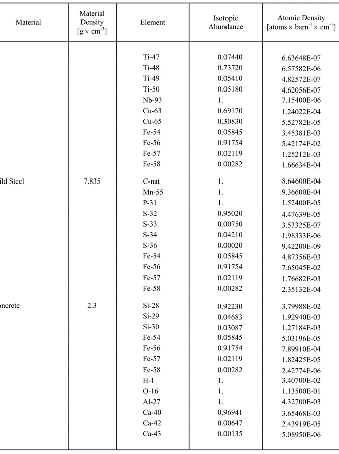
In particular the common set of atomic densities used in the calculations with the BUGJEFF311.BOLIB and BUGENDF70.BOLIB libraries is reported in TAB. 4.1 while the different set of atomic densities shown in TAB. 4.2 was used in the calculations with the BUGLE-96 library.
Both infinite dilution and self-shielded cross sections were selected. Self-shielded cross sections from the three library packages were used when available. In particular it is underlined that the thermal shield (stainless steel) and the pressure vessel (mild steel) simulators of the PCA-Replica experiment were characterized by atomic densities quite similar to those used to calculate the background cross sections employed in the self-shielding of the BUGJEFF311.BOLIB, BUGENDF70.BOLIB and BUGLE-96 neutron cross sections. Group-organized files of macroscopic cross sections, requested by TORT-3.2 and derived from the cited working libraries in FIDO-ANISN format, were prepared through the ORNL GIP (see /14/) program, specifically dedicated to the discrete ordinates transport codes (ANISN-ORNL, DORT, TORT) of the DOORS system. The ENEA-Bologna ADEFTA-4.1 program was used not only to calculate the atomic densities for the benchmark experiment compositional model but also to handle them properly in order to automatically prepare the macroscopic cross section sets of the compositional model material mixtures in the format required by GIP.
Fixed source transport calculations with one source (outer) iteration were performed using fully symmetrical discrete ordinates directional quadrature sets for the flux solution.
The P3-S8 approximation was adopted as the standard reference. PN corresponds to the order of the expansion in Legendre polynomials of the scattering cross section matrix and SN represents the order of the flux angular discretization. It is underlined that the P3-S8 approximation is the most widely used option in the fixed source calculations dedicated to LWR safety analyses.
A further parametric analysis was carried out on the PN and SN orders. P3 calculations were performed with different sets of fully symmetrical quadrature for the S8, S12 and S16 orders of the flux angular discretization. Similarly, P5 calculations were performed with different sets of fully symmetrical quadrature for the S12 and S16 orders of the flux angular discretization. The BUGJEFF311.BOLIB library was exclusively used to perform this parametric analysis. The theta-weighted difference approximation was selected for the flux extrapolation model. In all the calculations the same numerical value (1.0E-03) for the point-wise flux convergence criterion was employed.
The vacuum boundary condition was selected at the left, right, inside, outside, bottom and top geometrical boundaries.
The IRDF-2002 /16/ derived (see /15/ and 3.4) flat weighting neutron dosimeter cross sections
in the BUGLE-96 47-group neutron energy structure for the Rh-103(n,n')Rh-103m, In-115(n,n')In-115m and S-32(n,p)P-32 nuclear reactions were used in all the calculations
with the BUGJEFF311.BOLIB, BUGENDF70.BOLIB and BUGLE-96 libraries to obtain the corresponding reaction rates in all the experimental dosimeter positions in water, steel and air. The use of the IRDF-2002 derived (see /15/ and 3.4) 1/4 T RPV weighting neutron dosimeter cross sections was properly limited, alternatively with the flat weighting cross sections, to obtain the dosimetric results in the measure positions (1/4 T RPV and 3/4 T RPV) located inside the mild steel RPV simulator.
Finally, in order to calculate with proper accuracy the neutron fluxes above 0.1, 1.0 and 3.0 MeV using the three libraries, the neutron flux contributions of the groups No. 27, No. 19 and No. 10 were respectively corrected by multiplying the cited group contributions by the following factors reported herewith (see TAB. B1 and pages 161-162 of reference /2/; see TAB. B1 and pages 167-168 of reference /3/; see TAB. 3.14 and page 66 of reference /7/), taking into account that the lower energy limits of the cited neutron groups do not correspond respectively to the 0.1, 1.0 and 3.0 MeV neutron energies.
Neutron Flux > 0.1 MeV
Group No. 27 Factor = 2.1034E-01 = ln(E0/Eg)/ ln(Eg+1/Eg) where: E0 = 0.1 [MeV];
Eg = 1.1109E-01 [MeV] (Upper energy limit group No. 27); Eg+1 = 6.7379E-02 [MeV] (Lower energy limit group No. 27). Neutron Flux > 1.0 MeV
Group No. 19 Factor = 1.3000E-02 = ln(E0/Eg)/ ln(Eg+1/Eg) where: E0 = 1.0 [MeV];
Eg = 1.0026 [MeV] (Upper energy limit group No. 19); Eg+1 = 0.82085 [MeV] (Lower energy limit group No. 19). Neutron Flux > 3.0 MeV
Group No. 10 Factor = 3.959E-02 = ln(E0/Eg)/ ln(Eg+1/Eg) where: E0 = 3.0 [MeV];
Eg = 3.0119 [MeV] (Upper energy limit group No. 10); Eg+1 = 2.7253 [MeV] (Lower energy limit group No. 10).
FIG. 4.1
PCA-Replica - Compositional and Geometrical Model in the TORT-3.2 (X,Y,Z) Calculations. Horizontal Section at Y = 0.0 cm.
TAB. 4.1
PCA-Replica - Atomic Densities Used in the TORT-3.2 Calculations Using the BUGJEFF311.BOLIB and BUGENDF70.BOLIB Libraries.
Material
Material Density
[g × cm-3] Element
Isotopic
Abundance [atoms × barnAtomic Density -1 × cm-1]
Graphite 1.65 C-nata 1. 8.27600E-02
Aluminium Cladding 2.70 Al-27 1. 6.02900E-02
Alloy Fuelb 3.257 Al-27 1. 5.81800E-02
U-235 0.93 1.55200E-03
U-238 0.07 1.15400E-04
Water 1.0 H-1 1. 6.68800E-02
O-16 1. 3.34400E-02
Stainless Steel 7.88 C-nat 1. 6.72100E-05
Si-28 0.92230 6.86007E-04 Si-29 0.04683 3.48322E-05 Si-30 0.03087 2.29611E-05 Mn-55 1. 1.35600E-03 P-31 1. 3.83200E-05 S-32 0.95020 8.44158E-06 S-33 0.00750 6.66300E-08 S-34 0.04210 3.74016E-07 S-36 0.00020 1.77680E-09 Cr-50 0.04345 7.33436E-04 Cr-52 0.83789 1.41436E-02 Cr-53 0.09501 1.60377E-03 Cr-54 0.02365 3.99212E-04 Ni-58 0.68077 5.17453E-03 Ni-60 0.26223 1.99321E-03 Ni-61 0.01140 8.66514E-05 Ni-62 0.03634 2.76220E-04 Ni-64 0.00926 7.03853E-05 Mo-92 0.14840 2.71720E-05 Mo-94 0.09250 1.69368E-05 Mo-95 0.15920 2.91495E-05 Mo-96 0.16680 3.05411E-05 Mo-97 0.09550 1.74861E-05 Mo-98 0.24130 4.41820E-05 Mo-100 0.09630 1.76325E-05 Ti-46 0.08250 7.35900E-07
TAB. 4.1 Continued
PCA-Replica - Atomic Densities Used in the TORT-3.2 Calculations Using the BUGJEFF311.BOLIB and BUGENDF70.BOLIB Libraries.
Material
Material Density
[g × cm-3] Element
Isotopic
Abundance [atoms × barnAtomic Density -1 × cm-1]
Ti-47 0.07440 6.63648E-07 Ti-48 0.73720 6.57582E-06 Ti-49 0.05410 4.82572E-07 Ti-50 0.05180 4.62056E-07 Nb-93 1. 7.15400E-06 Cu-63 0.69170 1.24022E-04 Cu-65 0.30830 5.52782E-05 Fe-54 0.05845 3.45381E-03 Fe-56 0.91754 5.42174E-02 Fe-57 0.02119 1.25212E-03 Fe-58 0.00282 1.66634E-04
Mild Steel 7.835 C-nat 1. 8.64600E-04
Mn-55 1. 9.36600E-04 P-31 1. 1.52400E-05 S-32 0.95020 4.47639E-05 S-33 0.00750 3.53325E-07 S-34 0.04210 1.98333E-06 S-36 0.00020 9.42200E-09 Fe-54 0.05845 4.87356E-03 Fe-56 0.91754 7.65045E-02 Fe-57 0.02119 1.76682E-03 Fe-58 0.00282 2.35132E-04
Concrete 2.3 Si-28 0.92230 3.79988E-02
Si-29 0.04683 1.92940E-03 Si-30 0.03087 1.27184E-03 Fe-54 0.05845 5.03196E-05 Fe-56 0.91754 7.89910E-04 Fe-57 0.02119 1.82425E-05 Fe-58 0.00282 2.42774E-06 H-1 1. 3.40700E-02 O-16 1. 1.13500E-01 Al-27 1. 4.32700E-03 Ca-40 0.96941 3.65468E-03 Ca-42 0.00647 2.43919E-05 Ca-43 0.00135 5.08950E-06
TAB. 4.1 Continued
PCA-Replica - Atomic Densities Used in the TORT-3.2 Calculations Using the BUGJEFF311.BOLIB and BUGENDF70.BOLIB Libraries.
Material
Material Density
[g × cm-3] Element
Isotopic
Abundance [atoms × barnAtomic Density -1 × cm-1]
Ca-44 0.02086 7.86422E-05 Ca-46 0.00004 1.50800E-07 Ca-48 0.00187 7.04990E-06 Na-23 1. 2.39000E-03 K-39 0.932581 1.31028E-03 K-40 0.000117 1.64385E-07 K-41 0.067302 9.45593E-05 Air 0.001205c N-14 0.99634 3.95960E-05 N-15 0.00366 1.45454E-07 O-16 1. 1.05642E-05
(a) C-nat means carbon natural element.
(b) Uranium enriched to 93 w% in U-235.
TAB. 4.2
PCA-Replica - Atomic Densities Used in the TORT-3.2 Calculations Using the BUGLE-96 Library.
Material
Material Density
[g × cm-3] Element
Isotopic
Abundance [atoms × barnAtomic Density -1 × cm-1]
Graphite 1.65 C-nata 1. 8.27600E-02
Aluminium Cladding 2.70 Al-27 1. 6.02900E-02
Alloy Fuelb 3.257 Al-27 1. 5.81800E-02
U-235 0.93 1.55200E-03
U-238 0.07 1.15400E-04
Water 1.0 H-1 1. 6.68800E-02
O-16 1. 3.34400E-02
Stainless Steel 7.88 C-nat 1. 6.72100E-05
Si-nat 1. 7.43800E-04 Mn-55 1. 1.35600E-03 P-31 1. 3.83200E-05 S-nat 1. 8.88400E-06 Cr-50 0.04345 7.33436E-04 Cr-52 0.83789 1.41436E-02 Cr-53 0.09501 1.60377E-03 Cr-54 0.02365 3.99212E-04 Ni-58 0.68077 5.17453E-03 Ni-60 0.26223 1.99321E-03 Ni-61 0.01140 8.66514E-05 Ni-62 0.03634 2.76220E-04 Ni-64 0.00926 7.03853E-05 Mo-nat 1. 1.83100E-04 Ti-nat 1. 8.92000E-06 Nb-93 1. 7.15400E-06 Cu-63 0.69170 1.24022E-04 Cu-65 0.30830 5.52782E-05 Fe-54 0.05845 3.45381E-03 Fe-56 0.91754 5.42174E-02 Fe-57 0.02119 1.25212E-03 Fe-58 0.00282 1.66634E-04
TAB. 4.2 Continued
PCA-Replica - Atomic Densities Used in the TORT-3.2 Calculations Using the BUGLE-96 Library.
Material
Material Density
[g × cm-3] Element
Isotopic
Abundance [atoms × barnAtomic Density -1 × cm-1]
Mild Steel 7.835 C-nat 1. 8.64600E-04
Mn-55 1. 9.36600E-04 P-31 1. 1.52400E-05 S-nat 1. 4.71100E-05 Fe-54 0.05845 4.87356E-03 Fe-56 0.91754 7.65045E-02 Fe-57 0.02119 1.76682E-03 Fe-58 0.00282 2.35132E-04
Concrete 2.3 Si-nat 1. 4.12000E-02
Fe-54 0.05845 5.03196E-05 Fe-56 0.91754 7.89910E-04 Fe-57 0.02119 1.82425E-05 Fe-58 0.00282 2.42774E-06 H-1 1. 3.40700E-02 O-16 1. 1.13500E-01 Al-27 1. 4.32700E-03 Ca-nat 1. 3.77000E-03 Na-23 1. 2.39000E-03 K-nat 1. 1.40500E-03 Air 0.001205c N-14 0.99634 3.95960E-05 N-15 0.00366 1.45454E-07 O-16 1. 1.05642E-05
(a) C-nat means carbon natural element.
(b) Uranium enriched to 93% in U-235.
4.2 - PCA-Replica Fission Neutron Source
As previously reported, a precise inhomogeneous fission neutron source distribution (see TAB. 2.3) in the fission plate (see FIG. 2.4) was adopted, following the recommended official specifications (see TAB. A6 and FIG. A1 of reference /9/).
The distributed (or volumetric) fission neutron sources used in the calculations with the BUGJEFF311.BOLIB /2/, BUGENDF70.BOLIB /3/ and BUGLE-96 /7/ libraries were obtained using respectively their corresponding fission neutron spectra reported in TAB. 3.7 (see 3.5).
The BUGJEFF311.BOLIB U-235 total (prompt + delayed) fission neutron spectrum (χ) data derived from JEFF-3.1.1 are reported in TAB. 3.7 and are identical to those shown in the TAB. C.1 of reference /2/ at page 165.
The BUGENDF70.BOLIB U-235 total (prompt + delayed) fission neutron spectrum (χ) data derived from ENDF/B-VII.0 are reported in TAB. 3.7 and are identical to those shown in the TAB. C.1 of reference /3/ at page 171.
The BUGLE-96 U-235 prompt fission neutron spectrum (χ) data derived from ENDF/B-VI.3 are reported in TAB. 3.7 and are identical to those shown in the TAB. 3.14 of reference /7/ at page 58. The total fission neutron spectrum data are not available in the BUGLE-96 library (see 3.5).
In order to determine the volumetric neutron source for each transport calculation with the three libraries, the common value of ν (U-235) = 2.437 was used for the average number of neutrons produced per U-235 thermal fission, as suggested in the official description (see page 49 of reference /9/) of the PCA-Replica experiment. This choice was addressed also to assure the consistent comparison of the calculated results.
4.2.1- Inhomogeneous Neutron Source
In the TORT calculations with the inhomogeneous neutron source, the 6.74E-04 fission plate Watts per NESTOR Watt numerical value (see page 48 of reference /9/) was given to the “xnf” source multiplier parameter in the 67** “problem parameters” array.
The numerical values given to the 96** “distributed source distribution” array correspond to the numerical values reported in TAB. 2.3 (derived from TAB. A6 of reference /9/), representing the fission plate neutron source spatial distribution.
4.2.2 - Homogeneous Neutron Source
In the TORT calculations with the homogeneous neutron source the “xnf” source multiplier parameter in the 67** “problem parameters” array was calculated as follows.
xnf = A × ν (U-235) / Vp = 3.3477E+04, where
A = 2.104E+07 fissions × s-1 × NESTOR Watt-1,
fission plate total fission rate per NESTOR Watt (see page 48 of reference /9/);
ν (U-235) = 2.437,
average number of neutrons emitted per thermal fission (see page 49 of reference /9/); Vp = 40.2 × 63.5 × 0.6 = 1531.62 cm3,
This choice is consistent with the numerical values given to the 96** “distributed source distribution” array where a unit neutron source density (1 neutron × cm-3 × s-1) was attributed to all the spatial cells corresponding to the fission plate alloy fuel volume. Therefore the total fission neutron source strength calculated by TORT through the 96** array and the xnf parameter is numerically equal to xnf × Vp.