Removal in Passive Safety Systems: Comparison of Thermal Hydraulic Features
Ente emittente CIRTEN
PAGINA DI G
UARDIA
Descrittori
Tipologia del documento: Collocazione contrattuale:
Rapporto Tecnico
Accordo di programma ENEA-MSE su sicurezza nucleare e reattori di IV generazione
Reattori e sistemi innovativi Sicurezza Nucleare
Argomenti trattati:
Sommario
The following report aims to compare and analyse the performance of innovative heat exchangers and passive safety systems (Decay Heat Removal Systems-DHRS), in different configurations, similarly to those proposed insevera Inew generation reactor projects.
Two in-vessel heat exchangers are described and adopted, namely the microchannel type and the helical
coil type. Two ex-vessel heat exchangers are used to create a closed loop, natural circulation, passive DHRS: anair cooled type and an isolation condenser type, dipped intoawater pool. The comparison ofthe invessel heat exchangers is made in steady state conditions and in an accident scenario, with the use of RELAP5 commerciai software.
The new generation reactor adopted as a reference test bed for the DHRS implementation and analysis is the 12S-LWR project from Georgia-Tech (an Integrai PWR of large size). In the steady state analysis, the two types of in-vessel heat exchangers designed to remove Y4 of the reactor power have been compared at full power andat reduced power considering aconstant mean temperature of the primary system.
The analysis allowed to highlight the features in terms of compactness, friction pressure losses and performances at different power levels. In the analysis during accident conditions, a System Black-Out (SBO) followed by the reactor scram is used. In this case, the heat exchangers compared are used as a part of the DHRS, considering two possible solutions for the ex-vessel ultimate heat sink (the isolation condenser and the air cooled heat exchanger), resulting in 4 different DHRS configurations. The simulations results are compared intwo chapters grouping them bythe common ultimate heat sink, inorder to isolate the effect on the transient ofthe heat exchanger.
Note
REPORT PAR 2013 LP1.C CERSE-POLlMI-POLlTO RL 1494/2014
Autori: M. Caramello, M. De Salve, B. Panella (POLITO), G. Maronati, M. E. Ricotti (POLlMI)
Copia n. In carico a:
2 NOME
FIRMA
1 NOME
FIRMA
O EMISSIONE
2
[or/~
I
t
NOME P. Meloni~
~L
-:
FIRMA
REV. DESCRIZIONE DATA CONVALIDA
(,De Hosa
Lavoro svolto in esecuzione dell’Attività LP1.C2.3
AdP MSE-ENEA sulla Ricerca di Sistema Elettrico - Piano Annuale di Realizzazione 2013
Progetto B.3.1 “Sviluppo competenze scientifiche nel campo della sicurezza nucleare e collaborazione ai programmi internazionali per il nucleare di IV generazione
POLITECNICO DI MILANO
Department of Energy - Nuclear Reactors Group
POLITECNICO DI TORINO
Energy Department
Compact Heat Exchangers/Steam Generators and Decay Heat
Removal in Passive Safety Systems: Comparison of Thermal
Hydraulic Features
Autori
Marco Caramello (POLITO) Mario De Salve (POLITO) Bruno Panella (POLITO) Giovanni Maronati (POLIMI) Marco E. Ricotti (POLIMI)
CERSE-POLIMI-POLITO RL 1494/2014 Settembre 2014
LP1.C2.3 2 CERSE-POLIMI-POLITO RL-1494/2014
Index
1
Abstract ____________________________________________________ 8
2
Introduction _________________________________________________ 9
3
Heat Exchangers Description __________________________________ 14
3.1
Microchannel heat exchangers _______________________________ 14
3.1.1 Microchannels fabrication processes 16
3.2
Helical coil heat exchangers__________________________________ 17
3.2.1 Geometry 17 3.2.2 Fluid-dynamics 19
3.3
Air Heat Exchangers _______________________________________ 21
3.4
In-Pool heat exchangers _____________________________________ 22
4
I
2S-LWR Project ____________________________________________ 28
5
RELAP5 simulation of passive DHRS___________________________ 34
5.1
The intermediate heat exchanger _____________________________ 40
5.2
The final heat sink _________________________________________ 40
5.3
Accident sequences _________________________________________ 40
6
Simulations results: steady state conditions ______________________ 42
6.1
Full power, steady state condition_____________________________ 43
6.2
Power load effect __________________________________________ 47
7
Simulations results: accident conditions with pump inertia neglected_ 52
7.1
Case 1: Helical Coil Heat Exch. (A) and Air Cooled Heat Exch. (C)_ 53
LP1.C2.3 3 CERSE-POLIMI-POLITO RL-1494/2014
8
Simulations results: accident conditions with pump inertia effect ____ 82
8.1
Case 3+4: Isolation Condenser (Pool) as final heat sink ___________ 84
8.2
Case 1+2: Air Cooled Heat Exchanger as final heat sink __________ 98
9
Conclusions _______________________________________________ 112
10
References _______________________________________________ 113
11
Appendix: components of the system _________________________ 121
11.1
Primary system __________________________________________ 121
11.2
Intermediate loop ________________________________________ 137
11.3
Primary system: microchannel heat exchanger________________ 146
11.4
Final heat sink: Pool loop__________________________________ 147
LP1.C2.3 4 CERSE-POLIMI-POLITO RL-1494/2014
List of figures
Figure 1. Schematic of microchannel heat exchangers...15
Figure 2. Schematic of an helical coil tube...17
Figure 3. Example of velocity profiles in a coiled pipe ...18
Figure 4. Different flow patterns in coiled pipes ...19
Figure 5. Chimney general layout and design parameters ...22
Figure 6. General layout of a pool-type heat exchanger ...23
Figure 7. BWR isolation condenser ...23
Figure 8. ESBWR layout ...25
Figure 9. ESBWR ICS layout ...25
Figure 10. PCCS layout ...26
Figure 11. passive safety systems for AP1000 ...27
Figure 12: schematic of the PRHRS in the AP1000 reactor...27
Figure 13. I2S layout and radial cross-section of the RPV [26, 51]...29
Figure 14. I2S insight ...30
Figure 15. Schematic of the flashing drum [26, 59] ...31
Figure 16. Helical coil DHRS coupled with air cooling [26, 60] ...32
Figure 17. Microchannel heat exchanger...33
Figure 18. Case 1, Relap5 model: helical coil heat exchanger + air cooled heat exchanger (A+C) .36 Figure 19. Case 2, Relap5 model: microchannels heat exchanger + air cooled heat exchanger (B+C) ...37
Figure 20. Case 3, Relap5 model: helical coil heat exchanger + isolation condenser (A+D) ...37
Figure 21. Case 4, Relap5 model: microchannels heat exchanger + isolation condenser (B+D)...38
Figure 22. Primary pressure (Case: steady state)...45
Figure 23. Temperatures (Case: steady state) ...46
Figure 24. Secondary pressure (Case: steady state)...46
Figure 25. Heat flux (Case: steady state) ...47
Figure 26. General layout of the model for power load analysis...48
LP1.C2.3 5 CERSE-POLIMI-POLITO RL-1494/2014
Figure 28. Normalized global heat transfer coefficient (Case: steady state, power load variation) ..50
Figure 29. Mean logarithmic temperature (Case: steady state, power load variation) ...51
Figure 30. Power load as a function of the inlet temperature (Case: steady state, power load variation) ...51
Figure 31. Primary pressure at the beginning of the transient (Case 1)...54
Figure 32. Primary pressure in the first 2 hours (Case 1) ...55
Figure 33. primary pressure (Case 1)...56
Figure 34. Core temperatures in the first 10 hours of the transient (Case 1) ...57
Figure 35. Primary temperatures during the transient (Case 1) ...57
Figure 36. Core flow rate in the first 10 hours (Case 1) ...58
Figure 37. Core flow rate (Case 1)...59
Figure 38. intermediate loop pressure (Case 1) ...60
Figure 39. Intermediate loop pressure at start-up (Case 1) ...60
Figure 40. Intermediate loop temperatures at start-up (Case 1)...61
Figure 41. Intermediate loop temperatures (Case 1)...62
Figure 42. Intermediate loop flow rate at start-up (Case 1)...63
Figure 43. Intermediate loop flow rate (Case 1) ...63
Figure 44. Air temperatures at start-up (Case 1)...64
Figure 45. Air temperatures (Case 1)...65
Figure 46. Air flow rate at start-up (Case 1) ...66
Figure 47. Air flow rate (Case 1) ...66
Figure 48: Thermal power at the beginning of the transient (Case 1) ...68
Figure 49. Power removed in the first 30 hours (Case 1) ...68
Figure 50. Power removed in the long term (Case 1) ...69
Figure 51. Primary pressure at start-up (Case 3) ...71
Figure 52. Primary pressure after 2 hours (Case 3) ...71
Figure 53. Primary system’s pressure (Case 3)...72
Figure 54. Primary system's temperatures – start-up (Case 3)...73
Figure 55. Primary system temperatures in the long term (Case 3)...73
LP1.C2.3 6 CERSE-POLIMI-POLITO RL-1494/2014
Figure 57. Primary flow rate (Case 3)...75
Figure 58. Intermediate loop pressure at start-up (Case 3) ...76
Figure 59. Intermediate loop pressure (Case 3) ...76
Figure 60. Intermediate loop temperatures at start-up (Case 3)...77
Figure 61. Intermediate loop temperatures (Case 3)...78
Figure 62. Intermediate loop flow rate at start-up (Case 3)...79
Figure 63. Intermediate loop flow rate (Case 3) ...79
Figure 64. Power removed at the system start-up (Case 3) ...80
Figure 65. Power removed during the first hour (Case 3) ...81
Figure 66. Power removed in the long term (Case 3) ...81
Figure 67. Primary pump flow rate after SBO...83
Figure 68. Secondary pump flow rate after SBO [kg/s] ...83
Figure 69. Primary pressure (Case 3+4) ...84
Figure 70. Primary pressure at the beginning of the transient (Case 3+4)...85
Figure 71. Primary system’s temperatures in the first hour (Case 3+4) ...86
Figure 72. Primary system's temperatures during the first 10 hours (Case 3+4)...87
Figure 73. Primary system's temperature (Case 3+4) ...88
Figure 74. Core flow rate (Case 3+4) ...89
Figure 75. Core flow rate (Case 3+4) ...90
Figure 76. Core flow rate at the beginning of the transient (Case 3+4)...90
Figure 77. Intermediate loop pressure (Case 3+4)...91
Figure 78. Intermediate loop pressure at the beginning of the transient (Case 3+4) ...92
Figure 79. Intermediate loop pressure in the first 10 hours (Case 3+4) ...92
Figure 80. Intermediate loop temperatures (Case 3+4) ...93
Figure 81. Intermediate loop temperatures (Case 3+4) ...94
Figure 82. Intermediate loop flow rates in the long terms (Case 3+4) ...95
Figure 83. Intermediate loop flow rates in the first 10 hours (Case 3+4)...95
Figure 84. Intermediate loop flow rates at the beginning of the transient (Case 3+4) ...96
Figure 85. Thermal power (Case 3+4)...97
LP1.C2.3 7 CERSE-POLIMI-POLITO RL-1494/2014
Figure 87. Primary system's pressure (Case 1+2)...98
Figure 88. Primary system's pressure in the first 10 hours (Case 1+2)...99
Figure 89. Primary system's pressure in the first hour (Case 1+2) ...99
Figure 90. Primary temperatures (Case 1+2)...100
Figure 91. Primary temperatures in the first 10 hours (Case 1+2)...101
Figure 92. Primary temperatures at the beginning of the transient (Case 1+2) ...102
Figure 93. Core flow rate (Case 1+2) ...103
Figure 94. Core flow rate at the beginning of the transient (Case 1+2)...103
Figure 95. Intermediate loop pressure (Case 1+2)...104
Figure 96. Intermediate loop pressure at the beginning of the transient (Case 1+2) ...105
Figure 97. Intermediate loop temperatures (Case 1+2) ...106
Figure 98. Intermediate loop temperatures at the beginning of the transient (Case 1+2)...106
Figure 99. Intermediate loop flow rate (Case 1+2)...107
Figure 100. Intermediate loop flow rate at the beginning of the transient (Case 1+2) ...108
Figure 101. Air temperature (Case 1+2) ...109
Figure 102. Air temperature at the beginning of the transient (Case 1+2) ...109
Figure 103. Air flow rate at the beginning of the transient (Case 1+2) ...110
LP1.C2.3 8 CERSE-POLIMI-POLITO RL-1494/2014
1 Abstract
The following report aims to compare and analyse the performance of innovative heat exchangers and passive safety systems (Decay Heat Removal Systems-DHRS), in different configurations, similarly to those proposed in several new generation reactor projects. Two in-vessel heat exchangers are described and adopted, namely the microchannel type and the helical coil type. Two ex-vessel heat exchangers are used to create a closed loop, natural circulation, passive DHRS: an air cooled type and an isolation condenser type, dipped into a water pool. The comparison of the in-vessel heat exchangers is made in steady state conditions and in an accident scenario, with the use of RELAP5 commercial software.
The new generation reactor adopted as a reference test bed for the DHRS implementation and analysis is the I2S-LWR project from Georgia-Tech (an Integral PWR of large size).
In the steady state analysis, the two types of in-vessel heat exchangers designed to remove ¼ of the reactor power have been compared at full power and at reduced power considering a constant mean temperature of the primary system. The analysis allowed to highlight the features in terms of compactness, friction pressure losses and performances at different power levels.
In the analysis during accident conditions, a System Black-Out (SBO) followed by the reactor scram is used. In this case, the heat exchangers compared are used as a part of the DHRS, considering two possible solutions for the ex-vessel ultimate heat sink (the isolation condenser and the air cooled heat exchanger), resulting in 4 different DHRS configurations. The simulations results are compared in two chapters grouping them by the common ultimate heat sink, in order to isolate the effect on the transient of the heat exchanger.
LP1.C2.3 9 CERSE-POLIMI-POLITO RL-1494/2014
2 Introduction
The objective of the major of components and fluids inside a nuclear station is to transfer thermal energy between the regions of the plants and between the plant and the external environment. The first heat transfer that takes place as nuclear energy is converted into heat is the one inside the core, where the refrigerant of the primary system removes energy from the fuel. The fuel itself may be of several geometries (small cylindrical pellets, spherical), while the refrigerant can be made of a single phase solution in case of light water, heavy water, liquid metals, molten salts and gas, or a two phase mixture in case of light water. The physical state of the refrigerant is the one obtained during nominal pressure and temperature conditions, but in case of water reactors a change of the physical state may happen during abnormal conditions.
The heat gained by the refrigerant of the core is normally transferred to a secondary system through intermediate heat exchangers or steam generators except in the case of boiling water or gas reactors, where the refrigerant has the potential to be sent directly to the turbine. These heat exchangers are used during nominal conditions and are characterized by different geometries and dimensions, surface areas and pressure losses, and for any different kind on plant in terms of power, thermodynamic cycle and refrigerant specific requirements (thermal-hydraulic, compactness, chemistry, economy) need to be fulfilled with different solutions. The most common steam generators and heat exchangers encountered in the existing nuclear fleet are made of straight pipes or U-tube pipes. Innovative geometries have been studied in the past and have been used in some commercial plants and several research reactors, as the helical coil, the bayonet and the spiral. The same components used for the heat removal during nominal conditions can be part of a safety system during accident conditions, though the working conditions are far from the nominal point they provide a large surface area in comparison to the heat produced in case of a protected transient. As another case, other heat exchangers different from the ones used in nominal conditions may be used to remove the power in accident scenarios: the design of specific components and of specific systems must be made taking into account a non-negligible variation of power passing from the first moments of the transient to the long term cooling, and for this reason several systems may be called
LP1.C2.3 10 CERSE-POLIMI-POLITO RL-1494/2014 into action in the same plant depending on the time of the transient starting from the initiating event.
Safety systems may have different goals depending on the time of the transient in which they are called: at a first stage, they may provide a cold storage of the coolant to reduce the specific internal energy of the primary system and avoid reaching excessive pressure or temperatures which may cause irreversible damages to the structures or to the core with possible hydrogen production and radioactive releases. In case of water reactors, the storage may be filled with borated water at a higher concentration than the one of the coolant to provide a negative reactivity insertion. These kinds of safety systems are not used for the heat removal from the primary system in a general sense, but they act to reduce the specific internal energy. Safety systems with the goal to remove power from the primary system, or more in general to the nuclear island, are the ones able to establish a continuous flow of heat through solid components or with the help of a flowing fluid, being it in a loop or not. Even these systems are not generic but specific for the type of plant.
As electric power is produced in the turbine, the fluid that underwent the expansion (the primary coolant or a secondary fluid) must release the remaining power to the external environment, and this duty is usually fulfilled with condensers in case of steam or other heat exchangers. The design of these heat exchangers is no more dependent only on the kind of plant, but also on the conditions of the external environment. Topology, topography, hydrology and meteorology of the site are examples of information needed for the construction of a thermal interface between the plant and the environment. The presence of water in the neighbourhood of the plant like the sea, rivers or lakes have the potential to be an excellent way to provide an external heat sink, so that in some cases of commercial plants artificial water basins are built to provide an external reservoir. In the absence of such natural sources, the heat sink may be provided by wet or dry evaporative towers, which make use of natural or assisted circulation of air. Even safety systems need an ultimate heat sink for the heat during incidental conditions, and if for any reason the nominal interfaces with the environment are not available other components must permit the heat removal from the plant. These systems are characterized by a lower power duty with respect to the ones used in nominal condition, although they may be forced to work in severe conditions, as in the case of a station black out. In this case, heat exchangers connected to natural circulation loops immersed in dedicated water storages, or smaller towers which make use of the natural circulation of air may provide an effective
LP1.C2.3 11 CERSE-POLIMI-POLITO RL-1494/2014 cooling of the system for a certain period of time in the first case, or a long-lasting cooling in the
second case.
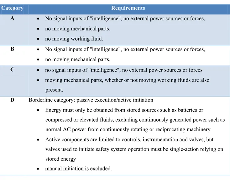
The aim of the following report is to analyse the applications of passive systems for the decay heat removal in advanced nuclear reactors and critically discuss different design choices and components in the light of the most promising and innovative configurations. In the framework of passive safety systems for nuclear applications the International Atomic Energy Agency in 1991 [1] set the first guidelines for the definition of passive systems. The degree of passiveness of a system can be assessed considering its characteristics with respect to the 4 categories listed in table 1.
Table 1: Passive systems categories
Category Requirements
A • No signal inputs of "intelligence", no external power sources or forces, • no moving mechanical parts,
• no moving working fluid.
B • No signal inputs of "intelligence", no external power sources or forces, • no moving mechanical parts,
C • no signal inputs of "intelligence", no external power sources or forces • moving mechanical parts, whether or not moving working fluids are also
present.
D Borderline category: passive execution/active initiation
• Energy must only be obtained from stored sources such as batteries or
compressed or elevated fluids, excluding continuously generated power such as normal AC power from continuously rotating or reciprocating machinery • Active components are limited to controls, instrumentation and valves, but
valves used to initiate safety system operation must be single-action relying on stored energy
LP1.C2.3 12 CERSE-POLIMI-POLITO RL-1494/2014 Among the four categories listed in Table 1 most of the decay heat removal systems (DHRS) belong
to category B or C since they make use of natural circulation for the fluid flow. The DHRS is the system that has the purpose to remove the decay heat in nominal or accident conditions from the primary system to the environment.
The complex set of thermal-hydraulic phenomena that occur in a gravity environment when geometrically or materially distinct heat sinks and heat sources are connected by a fluid can be identified as natural circulation [2, 3].
The studies of natural circulation in the past have been made both with experimental and numerical tools. From the point of view of the experimental tests on natural circulation, many facilities around the world have been built in the past to analyse transient phenomena, such as CAPCN, ITL, LSTF, PUMA and MASLWR. IAEA reports gathered a comprehensive list of information about the facilities [3], and several articles in public literature reports the results of the experiments performed [5-10]. From the point of view of the numerical analysis, thanks to the great effort in numerous experiments several code have been validated for the analysis of natural circulation, such as ATHLET, RELAP5, CATHARE2 and FLUENT [11].
To compare different configurations and components for the stability and efficiency of natural circulation systems, compact heat exchangers and steam generators must be contextualised in generic or specific layouts of safety systems because the behaviour of natural circulation is strongly dependent on both thermal and geometric specifications such as operating conditions and height differences, therefore a complete analysis can’t be made without specific constraints. To overcome the previous issue, the I2S integral reactor international project has been chosen as a reference geometry for the numerical analysis.
The tool chosen for the analysis is RELAP5-3D, version 4.0.3. The code is based on a nonhomogeneous and non-equilibrium model for the two-phase system that is solved by a fast, partially implicit numerical scheme to permit economical calculation of system transients [4]. The Relap5 code will be used to create a representative model of the system in terms of piping, components, heat sources and sinks.
The report is organized as following. The Chapter 3 covers the description of the heat exchangers considered for the DHRS. As a primary heat exchanger in contact with the primary system, a
LP1.C2.3 13 CERSE-POLIMI-POLITO RL-1494/2014 compact plate heat exchanger with micro channels and a helical coil heat exchanger are proposed as
possible solution, while the comparison for the external heat sink is made between an air heat exchanger and a pool heat exchanger. Chapter 4 presents the I2S-LWR project with a focus on its heat removal systems. Chapter 5 describes the Relap5 models used for the analysis, the boundary and initial conditions used and the accidental sequence. Chapter 6 reports the results of a comparative analysis between helical coil and microchannel heat exchangers. Chapters 7 and 8 reports the numerical simulations done for the accident sequence reported in Chapter 5 for the different configurations, as well as the results obtained. Finally, Chapter 9 contains a critical discussion of the results and a comparison among the possible solutions to highlight their benefits and drawbacks, as well as a description of the future works that needs to be done to deepen the knowledge on natural circulation safety systems.
LP1.C2.3 14 CERSE-POLIMI-POLITO RL-1494/2014
3 Heat Exchangers Description
3.1 Microchannel heat exchangers
One of the most important challenges of current technology is the removal of high thermal fluxes with the aim of very compact components. One way to address such issue is to enhance the convective heat transfer coefficient or increase the surface to volume ratio of the components. Among the different solutions there are the compact heat exchangers, which make use of microchannels. The application of microchannels is a fairly new field, which finds applications in biological and life science, biomedical and genetic engineering [12, 13] and also for the cooling of small electronic components [14]. Up to now the application of these heat exchangers has been done almost entirely for the removal of low thermal powers in a relatively small scale, but the high performance of these components is also interesting for larger modular devices which face higher values of power to be removed. In this context, the possibility arises to use compact microchannel heat exchangers for the decay heat removal in integral nuclear reactors, where critical constraints exist for the location of the primary components in the reactor pressure vessel.
The fluid dynamics in microchannels is strongly dependent on the flow characteristic, the geometry of the channel and the condition of the surface [15]. Channels with hydraulic diameters lower than 1 mm have a great geometrical impact in the enhancement of heat transfer, but, on the other hand, the frictional pressure loss per unit length results higher than the ones of standard-size heat exchangers. For this reason, the path of the fluid is kept as small as possible, and the developing flow region may be a non-negligible length fraction. To account the developing region for the frictional pressure loss it is common to use an apparent friction factor fapp, which is found to be dependent, both on the
position from the inlet (degree of development), on the Reynolds number and on the geometry of the cross section [16,17]. For the frictional pressure loss in fully developed laminar flow, the friction factor and the Reynolds number are usually correlated with the Poiseuille number (Po) as in equation 1.
LP1.C2.3 15 CERSE-POLIMI-POLITO RL-1494/2014 As for the developing region, the friction pressure loss in fully developed flow is dependent on the
Reynolds number and on the geometry of the cross section [18-20]. The laminar to turbulent transition in microchannels has also been studied recently [21]. It has been found that the transition happens with Reynolds numbers in the range of 2000-2300 and does not depend on the channel dimension.
As far as the heat transfer is concerned, for the laminar flow the Nusselt number is predicted as a function of the geometry of the cross section and on the boundary condition used (constant wall temperature, constant heat flux) [22].
As mentioned previously, the developing flow region plays an important role for the fluid dynamics in microchannel, and this is also true for the heat transfer. Different correlations are available in literature where the Nusselt number dependent to the distance from inlet the Reynolds number and the Prandtl number [18,19,23]. For fully developed turbulent flow, Adams et al. [24] suggested to correlate the Nusselt number to the one obtained by the Gnielinski correlation [25] corrected by a geometrical factor that takes into account the heat transfer enhancement provided by the microchannel.
For the heat exchangers taken into account in this study, a series of corrugated plates are stacked together and squared cross section channels are formed for the fluids. Figure 1 shows a schematic of the heat exchanger module currently under study for the steam production, as well as the flow path of the fluids [26].
LP1.C2.3 16 CERSE-POLIMI-POLITO RL-1494/2014
3.1.1 Microchannels fabrication processes
Microchannel heat exchangers can be manufactured through miniaturized traditional technologies and “modern” innovative technologies. Miniaturized traditional techniques are rooted in conventional machine shop and manufacturing practices but adapted to achieve microscale features [27]. Some of these techniques, such as lithography, laser exposure, electroplating and molding, have been widely adopted and are encountered in multiple fabrication methodologies. The “modern” technologies are more difficult to characterize but are generally based on advances that occurred in the latter half of the twentieth century, such as lasers and micron-level photolithography. In some respects, miniaturized traditional techniques are the most straightforward approach to creating micro-features.
Standard machining techniques, such as sawing and micro-electro discharge machining can readily produce channels at dimensions down to a few hundred microns. Other Miniaturized traditional techniques, such as ultrasonic and waterjet machining are demonstrated to be very effective, especially on hard brittle materials. Commercial electroforming, molding, and stereolithographic fabrication have been brought into the micro-regime through the incorporation of lithographic and laser-based patterning.
As opposed to traditional technologies, “modern” technologies are able to accommodate channels down to few microns, with low material removal rates and low throughput. However, these techniques are often used for specialized high-value, low-repetition operations like micro-feature repair and via formation. These techniques have been reviewed by many authors [28, 29]. Laser machining has become an increasingly powerful tool that can handle a wide variety of difficult materials. Focused ion beam machining offers many similar benefits and can operate in the submicron regime.
LP1.C2.3 17 CERSE-POLIMI-POLITO RL-1494/2014
3.2 Helical coil heat exchangers
3.2.1 Geometry
Heat exchangers composed of helical coiled pipes are currently used in process industries and power plants for their great capability to remove high thermal fluxes with a high degree of compactness even if with non-negligible pressure drops. The geometry of an helical pipe is defined by an internal and external diameter (di, de), an helical diameter Dh, the pitch ph and a number of
turns N as in figure 2 where N=2. All the equations of the paragraph are reported in Table 2 at the bottom.
Figure 2. Schematic of an helical coil tube.
The length of the coil is obtained from equation 1. A heat exchanger or steam generator is equipped with several helical coils set in parallel with different helical radii and pitches. Different families of coils can be gathered together by defining two dimensionless quantities, namely the curvature ratio δ as in equation 2 and the torsion ratio τ as in equation 3 [30].
The curvature ratio and the torsion ratio are not used just for the geometry characterization but also for the fluid dynamics because it is affected by these quantities. The peculiarity of coiled pipes is the presence of centrifugal forces in the Navier-Stokes equations. The unbalance between
LP1.C2.3 18 CERSE-POLIMI-POLITO RL-1494/2014 centrifugal, inertial and gravity forces lead to the formation of secondary motions lying on the
pipe’s cross section which create an alteration of the velocity and temperature fields with respect to the ones of a straight pipe. The motion of the fluid particles along the streamlines is not parallel to the helix centreline, and the particles experiences a series of accelerations and decelerations while moving in different regions of the velocity field.
The velocity maximum is shifted from the centre of the cross section to the external peripheral region. The temperature field has the same characteristics of the velocity field: considering a cold fluid flowing in an helical pipe heated from the external side, the coldest region on the cross section will be shifted from the centre to the peripheral region. The weight of these phenomena is related to the values of the curvature ratio. For high values of the curvature ratio the centrifugal forces dominate over gravity and inertia and so the asymmetry is pronounced, while if the curvature ratio tends to zero the flow field inside the helical pipe tends to the one of a straight horizontal pipe. Figure 3 shows the typical velocity field of a fully developed flow in a coiled pipe [33].
Figure 3. Example of velocity profiles in a coiled pipe
Another important feature of the coiled pipes is the tendency to laminarize the flow. Not only the laminar to turbulent transition happens at higher Reynolds number with respect to a straight pipe, also the transition is smoother. These effects increase as the curvature ratio increases. Cioncolini et
LP1.C2.3 19 CERSE-POLIMI-POLITO RL-1494/2014 al. [31] studied experimentally the laminar to turbulent transition in coiled pipe highlighting the
causes of the enhancement of the laminar region.
3.2.2 Fluid-dynamics
As far as heat transfer and pressure drops are concerned, many reviews are available in literature, covering the researches done from the first studies to the last years’ [32-38]. The heat transfer in coiled pipes is strongly asymmetric because of the centrifugal forces: the heat transfer coefficient and the wall temperatures are not constant on the cross-section. The highest values of heat transfer coefficient are recorder on the external side of the curvature, while the lowest ones are in the inner part. For an estimation of the average heat transfer coefficient in single-phase flow the most validated correlations are the one by Mori and Nakayama [40] which are reported in equations 4 and 5. Equation 4 is valid for liquids while equation 5 is for superheated steam and gas.
During two-phase flow the centrifugal forces have a separation effect on the phases depending on their densities: the heavier phase is shifted towards the external side of the curvature. The parting capacity is used in industrial processes for liquid extraction or slurry separation. The curvature ratio also affects the flow pattern of the phases, as it can be seen from figure 4 [33].
Figure 4. Different flow patterns in coiled pipes
The heat transfer coefficient estimation is usually based on modified versions of the Chen [40] correlations for subcooled and saturated flow boiling such as the one from Owhadi [41] where the centrifugal forces are taken into account by adding the curvature ratio in the equations.
The frictional pressure losses are evaluated using equation 6.
One of the most validated correlations for the friction factor calculation in coiled pipe is the one by Ito [42] in system 7.
LP1.C2.3 20 CERSE-POLIMI-POLITO RL-1494/2014 In system 8 Recrit is the laminar to turbulent Reynolds transition number. Several correlations for the
calculations of this parameter are available in [31].
The estimation of frictional pressure drop in two phase flow is usually done with the aim of two-phase multipliers. Santini et al. [43] analysed experimentally the two-two-phase pressure drops inside helical coiled pipe and compared the experimental results with several correlations available in literature, underlining the increased pressure loss with respect to a straight pipe.
Table 2: equations for Helical Coil Heat Exchangers
LP1.C2.3 21 CERSE-POLIMI-POLITO RL-1494/2014
3.3 Air Heat Exchangers
Another key component of the system has the aim to provide an heat sink in order to remove the decay heat from the secondary loop and transfer it to an external environment, being it the ambient or a third system. The component designed for this purpose must accomplish the task by means of several constraints:
It must be a passive system without the need of intelligent signal for activation, It must guarantee the heat removal for a minimum amount of time (grace time).
Considering the lessons learned from the recent Fukushima accident the meaning of grace time has become more important since the condition of an isolated system for a long period of time without the possibility of human intervention is now important to be carefully investigated. As an extreme scenario, the perfect heat sink from the safety point of view must be able to remove indefinitely the power of the system without any human intervention.
The first system proposed for the task and described hereafter in this paragraph has the potential capability to successfully guarantee this last condition. It is constituted by a chimney containing a tube bundle where the secondary fluid circulates. The bundle is composed of parallel vertical or slightly inclined pipes, externally cooled by air at ambient pressure and temperature which flows in natural circulation thanks to the head provided by the height of the chimney. Figure 5 shows the general layout of a commercial chimney and the key parameters to be determined [44].
As a general rule, the dimension of the chimney can be assessed considering the following design parameters [44].
LP1.C2.3 22 CERSE-POLIMI-POLITO RL-1494/2014 For secondary fluid flowing inside the tube bundle the heat transfer conditions that may arise are a
single phase natural convection of a two-phase condensation.
Figure 5. Chimney general layout and design parameters
3.4 In-Pool heat exchangers
Another possible solution for the final heat sink is constituted by a heat exchanger immersed in a water pool. With this configuration, the fluid from the secondary loop transfers heat to a mass of water stored in a dedicated pool initially set at ambient pressure and temperature. Figure 6 shows a general layout of the system. The water inside the pool evaporates because of the heat transfer and the level of water reduces during time. As a general rule, the height of the pool is designed to keep the level of water above the top of the heat exchanger when the power to be removed from the primary system is high. For long term cooling the decay heat decreases and the water level drops under the top of the heat exchanger: during these conditions the free convection of the surrounding air is sufficient to remove the decay heat. The amount of water required as well as the height of the pool are calculated on the basis of the latent and sensible heat needed for the complete evaporation of water starting from ambient pressure and temperature. Considering that the pool must be installed at a higher altitude with respect to the reactor core to establish natural circulation, the
LP1.C2.3 23 CERSE-POLIMI-POLITO RL-1494/2014 design of the pool height is made as a compromise between the need to guarantee a water head on
the heat exchanger for a certain period of time and ensure the system integrity during the design basis earthquake.
Figure 6. General layout of a pool‐type heat exchanger
The first applications of this system have been done in the first boiling water reactors like the Dresden 1 in 1995 in the USA. The system is called isolation condenser (IC). Figure 7 [45] shows the layout of the heat exchanger and the connections with the primary system. When the system starts its operations the steam is sent from the upper part of the RPV to the immersed tube bundle where it condensate. The liquid is then redirected to the RPV establishing an assisted circulation loop with the recirculation pumps.
LP1.C2.3 24 CERSE-POLIMI-POLITO RL-1494/2014 In the last years the concept of isolation condenser has turned back into favour in numerous reactor
projects. One of them is the ESBWR (Economic Simplified Boiling Water Reactor). Figure 8 shows a layout of the reactor [46].
The ESBWR is a III+ generation boiling water reactor. It is characterized by a simple and safe design where the coolant is driven by natural circulation both in nominal and incidental conditions [47]. A pool-type system is used both for the pressure increase suppression or residual heat removal when the normal DHRS is unavailable (ICS) and also for the cooling system of the containment during LOCA. This second system is called passive containment cooling system (PCCS) [48]. The ICS is constituted by 4 independent trains set above the containment. Figure 9 shows a train of the ICS [46]. The pool is connected to the environment by means of the venting system. each pool is used respectively by a train of ICS and a train of PCCS. The ICS receive steam from the RPV from which it is injected in two immersed heat exchangers formed by tube bundles connected with headers at the top and at the bottom. The condensate is then redirected with a direct connection to the RPV on the top of the downcomer. The steam-side connection is normally open while the condensate line is closed. This allows the system to be full of subcooled water at the system pressure and reduce the start-up operations. Once the system is completely connected to the RPV a natural circulation is established at least for 72 hours.
Figure 10 represents the layout of one of the six PCCS trains [46]. The system is similar to the ICS except for the steam inlet of the heat exchangers which is connected to the containment’s environment. The aim of the system is to condensate the steam in the containment after a LOCA scenario and redirect the mixture of condensate and noncondensable gases to the gravity driven cooling system pool and the suppression pool respectively. The system has no valves and does not need activation.
LP1.C2.3 25 CERSE-POLIMI-POLITO RL-1494/2014 Figure 8. ESBWR layout
LP1.C2.3 26 CERSE-POLIMI-POLITO RL-1494/2014 Figure 10. PCCS layout
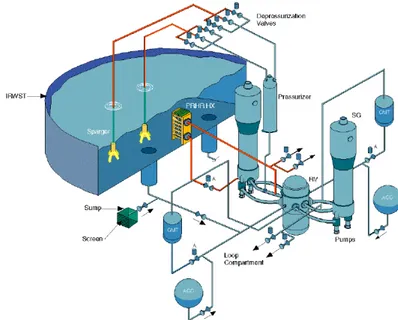
Another recent project which uses pool-type heat exchangers is the AP1000 [49]. AP1000 is a III+ generation two loop PWR born from the previous knowledge of the Westinghouse company in the AP600 project: it is designed with proven technologies for a near term licensing and makes great use of safety passive systems. Figure 11 shows the safety systems employed for the reactor [48]. The passive residual heat removal system is equipped with a C shaped heat exchanger which protects the plant against transients that upset the normal steam generator feedwater and steam systems. The heat exchanger is immersed in the In-Containment Refuelling Water Storage Tank (IRWST). When the system is called in operations valves are open and water from the hot leg is sent to the heat exchanger in the pool where it is cooled by the stored refuelling water. After that, the coolant is sent to the one of the steam generator cold-leg channel heads. This system can also operate while the primary pumps are working [48]. Figure 12 shows a layout of the PRHR system [50].
LP1.C2.3 27 CERSE-POLIMI-POLITO RL-1494/2014 Figure 11. passive safety systems for AP1000
LP1.C2.3 28 CERSE-POLIMI-POLITO RL-1494/2014
4 I
2S-LWR Project
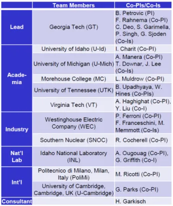
The I2S-LWR project [51] is the result of an international collaboration consisting of numerous research centres, universities and actors of the nuclear industry. The list of the principal actors is shown in Table 3.
Table 3: research group for I2S project
The combination of the economics provided by large electrical power, Inherent safety features and passive safety systems are the basis of the I2S-LWR (Integral Inherently Safe Light Water Reactor) concept based from the previous knowledge gained during the IRIS project [52-54].
Figure 13 shows the layout of I2S reactor. Most of the principal components are still under investigation at the moment and for each of them different solutions are currently under study; for
LP1.C2.3 29 CERSE-POLIMI-POLITO RL-1494/2014 this report, the description of the reactor will focus on the safety system components proposed for
the DHRS, and the rest of the system will be explained in terms of possible solutions.
The reactor is an integral PWR: pressurizer, control rod mechanism, primary heat exchangers and safety systems are integrated within the reactor pressure vessel (RPV), and the RPV is surrounded by a pressurized steel containment vessel (CV). Figure 14 shows the insight of the reactor with a particular of the control rods mechanism, the core barrel and the DHRS in the configuration with the helical coil heat exchanger. The main penetrations on the RPV are at a higher height than the core top.
Figure 13. I2S layout and radial cross‐section of the RPV [26, 51]
The reactor core is designed to obtain higher values of power density than typical pressurized water reactors (PWRs) in the order of 130 MWth/m3. To achieve this condition, innovative fuel pins in
composition and geometry are considered to maintain a satisfactory thermal margin in terms of distance from the melting temperature. The primary choice consists of U3Si2 cylindrical pellets and
high corrosion resistance stainless steel cladding. The secondary choice is to use UN petal-shaped rods and SiC as cladding.
LP1.C2.3 30 CERSE-POLIMI-POLITO RL-1494/2014 The 8 primary heat exchangers are made of stacks of plates among which microchannels are formed
where the fluids flow in single-phase conditions. From the preliminary analysis two-phase flow on the secondary side is not suggested because of instabilities that may arise inside the small channels of the heat exchanger. Also, two-phase flow may induce unacceptable pressure losses due to friction and probable channel blockage due to deposition of corrosion products. The steam is then produced in 4 flashing drums outside the RPV [59]. Figure 15 shows a schematic of the flashing drum. The fluid entering the volume experiences an abrupt pressure reduction reaching the pressure where its temperature is the saturation temperature and steam is produced. The steam is mechanically separated from the liquid phase with a separator on the top of the drum and is then sent to the high pressure stage of the turbine.
LP1.C2.3 31 CERSE-POLIMI-POLITO RL-1494/2014 Figure 15. Schematic of the flashing drum [26, 59]
Microchannel heat exchangers give the opportunity to reach high values of power density and therefore they provide a good solution for integral reactors, although many phenomena are still to be numerically and experimentally investigated to understand their behaviour during anomalous and incidental conditions, as it will be partially done in this report.
From the base of safety philosophy of the GEN-III+ reactors the I2S project have the aim to further increase the safety of LWRs with an inherent safety approach by eliminating accident initiators as much as achievable, limiting the loss of inventory during loss of coolant accident (LOCA) scenarios and increasing the components’ degree of passiveness above category C.
The DHRS [60] is equipped with four independent loops designed for a category B passivity thanks to the absence of valves. Each loop consists of a compact heat exchanger (microchannel or helical coil). In case of the helical coil heat exchanger, the tube side is connected to the primary system and the shell side is connected to the secondary loop. The fluid for the secondary loop is currently under study, and the most promising solutions are the ones with molten salts or nanofluids rather than water because of the heat transfer enhancement [56, 57]. The ultimate sink of the system is under investigation and the possible solutions are an air-cooled heat exchanger and a pool-type heat exchanger.
Figure 16 shows the layout of the in-vessel heat exchanger in case of the helical coil configuration coupled with the air-cooling sink.
LP1.C2.3 32 CERSE-POLIMI-POLITO RL-1494/2014 Figure 16. Helical coil DHRS coupled with air cooling [26, 60]
In the configuration proposed in figure 4 the primary fluid enters the annular region around the discharge tube. The inlet position is located in the downcomer region at the same height of the top of the core. Then, the hot primary fluid goes up to the heat exchanger and is subsequently sent in the helical tube where the heat is transferred to the shell side. Once the fluid completed the passage in the helical tube it descends into the discharge conduit and is sent back into the lower region of the downcomer to re-enter the core.
The second possibility for the DHRS is to use the same type of heat exchanger used for the steam production. These are compact microchannel heat exchangers. Figure 17 shows an example of an heat exchanger, the plates and the microchannels.
With this configuration, the DHRS are placed at the top of the downcomer region. The hot primary fluid goes from the riser into the heat exchanger and then it descends in the downcomer.
LP1.C2.3 33 CERSE-POLIMI-POLITO RL-1494/2014 Figure 17. Microchannel heat exchanger
LP1.C2.3 34 CERSE-POLIMI-POLITO RL-1494/2014
5 RELAP5 simulation of passive DHRS
In this chapter, the four different DHRS configurations and related RELAP5 inputs are reported. All the analyses were performed using a semi-implicit advancement scheme with time step control. The analysis has been carried out considering four different configurations of the DHRS in terms of in-vessel and external heat exchangers, but the architecture of the system and some parameters are the same in order to make the results comparable. The chapter is organized in the following way: in the first part, a general description of the loops and of the common components is presented. In the second part, the heat exchangers of the DHRS are described and the different solutions are compared in terms of modelling. In the appendix, a description of the cards used for the modelling of the single components is reported.
The model is divided into 4 subsystems representing 1/4 of the total system (since 4 trains of DHRS are envisaged for the reactor):
A= Helical Coil HEX
B= Microchannel Compact HEX C= Air cooled HEX
LP1.C2.3 35 CERSE-POLIMI-POLITO RL-1494/2014 The primary loop (reactor)
The secondary loop (steam generator) The intermediate loop (DHRS) The final heat sink
The four different configurations of the passive safety system are here summarized:
DHRS configuration In-vessel HX External HX
Case 1 (A+C) Helical Coil Heat Exchanger (A) Air Cooled Heat Exchanger (C)
Case 2 (B+C) Microchannel Heat Exchanger (B) Air Cooled Heat Exchanger (C)
Case 3 (A+D) Helical Coil Heat Exchanger (A) Isolation Condenser (Pool) (D)
Case 4 (B+D) Microchannel Heat Exchanger (B) Isolation Condenser (Pool) (D)
A general view of the whole system modelled with RELAP5 code is depicted in the Figures from 18 to 21, corresponding to the four different configurations for the DHRS. The figures are not in scale.
LP1.C2.3 36 CERSE-POLIMI-POLITO RL-1494/2014 Figure 18. Case 1, Relap5 model: helical coil heat exchanger + air cooled heat exchanger (A+C)
LP1.C2.3 37 CERSE-POLIMI-POLITO RL-1494/2014
Figure 19. Case 2, Relap5 model: microchannels heat exchanger + air cooled heat exchanger (B+C)
LP1.C2.3 38 CERSE-POLIMI-POLITO RL-1494/2014 Figure 21. Case 4, Relap5 model: microchannels heat exchanger + isolation condenser (B+D)
The primary system is the one drawn with blue volumes. The core (Pipe 101) is modelled as a single channel made of 10 volumes with more or less 1 m diameter and 3.65 m height, considering a negligible bypass flow rate. The heat structure linked to the core (101) is modelled with an internal heat source, characteristic of the nominal power during full power conditions and of the decay heat after the scram signal. Heat structure 101 is designed in order to simulate the fuel pin, with a cylindrical volume made of UO2, an helium gap and a stainless steel clad. The power during nominal condition is distributed with the characteristic chopped cosine. Adiabatic boundary condition is set on the left side of the heat structure while a convective boundary condition is set on the right side. From the core, the fluid passes into a 10 m riser (Pipe 102) and reaches the upper plenum of the vessel, which works as the pressurizer of the system as for other SMRs. The pressurizer is linked to three safety relief valves with increasing pressure set points starting from 157 bar. From the upper plenum the fluid moves into the annular region beside the riser. In this region, microchannel heat exchangers having 1 m2 area and 20 cm length are installed (Pipe 107) to remove the heat during full power conditions and transfer energy to the secondary system of the steam production line. Before the heat exchangers for the full power condition primary pumps
LP1.C2.3 39 CERSE-POLIMI-POLITO RL-1494/2014 (Time dependent junction 504) are installed to ensure the correct flow rate distribution. The other
components installed in the annular region are the DHR heat exchangers (Pipe 112), which in this case have an helical coil or microchannel geometry depending on the simulation. During nominal conditions a passive valve (Time dependent junction 506) is set at the inlet of the components to avoid heat losses and isolate the DHR system. By the time the scram signal is sent to the safety system these valves are opened and the flow is permitted, linking the primary system with the intermediate loop. The valve in the model is represented by a time dependent junction with a null flow rate during nominal conditions. When the scram signal is sent and the DHR is called the time dependent junction is substituted with a single junction with a null flow rate initial condition. The annular region ends in the lower plenum of the vessel (Single volume 110), where the refrigerant is sent back to the core to restart the turn.
The secondary loop for the steam production is simplified to the interaction region with the primary system. The model considers a flow rate inlet with a time dependent junction (550) modelling the feedwater pump, the heat transfer region inside the microchannel heat exchangers (Pipe 402) and a pressure outlet boundary condition (time dependent volume 403). During the nominal conditions the flow rate imposed is the nominal flow rate.
The intermediate loop is modelled as a simplified connection loop from the primary system to the final heat sink. The intermediate loop is initially detached from the primary system, and it’s initial conditions are of an ambient pressure and temperature. The secondary loop is connected with the primary system with the helical coil/microchannel heat exchanger tank (Pipe 201), which in the case of the helical coil heat exchanger has an area of 0.1315 m2 and a total length of 8 meters. From the outlet of the heat exchanger, the flow is sent to the final heat sink heat exchanger through a connection pipe (202) which has a diameter of 50 cm and a length of 15 meters. Linked to the connection pipe, a time dependent volume (204) gives the pressure boundary condition for the system. At the time the scram signal is sent, the time dependent volume is substituted with a pressurizer component linked to 3 safety relief valves. The fluid in the intermediate loop is thermally linked to the final heat sink with pipe 203, which is the equivalent condensed pipe of the air heat sink heat exchanger or the isolation condenser depending on the simulation. As the fluid is
LP1.C2.3 40 CERSE-POLIMI-POLITO RL-1494/2014 cooled in the final heat sink, the flow is redirected to the intermediate heat exchanger to remove
once again the decay heat.
The final heat sink is the only system whose components are completely different depending on the solution (air heat sink or isolation condenser) and the description will be given hereafter.
5.1 The intermediate heat exchanger
The intermediate heat exchanger configurations are a helical coil heat exchanger or a microchannel heat exchanger. The two configurations are comparable since they have been designed considering an equal outer surface area on the primary system side. The helical coil heat exchanger has been modelled following the instruction of the Idaho national laboratory [58], which suggest to use an equivalent inclined pipe whose length and height is the same as the real coil. The heat exchanger is made of 304 helical coils set in parallel with a length of 38 meters. The refrigerant passes inside the helical pipes while the intermediate loop water passes on the shell side in a closed tank inside the RPV. The microchannel heat exchanger is a scaled-down component whose geometry is the same as for the microchannel heat exchangers used for the steam production line. It has 510 000 parallel microchannels with square cross section of 1 mm. The detailed dimensions of the components are reported in the appendix.
5.2 The final heat sink
The final heat sink configurations are an isolation condenser system and an air heat exchanger. Since the two system have an high difference in heat transfer (one is made with water while the other with air) the common point for the system is the difference in height between the intermediate heat exchanger and the final heat sink, which has been fixed at 15 meters. The surface area ratio between the two solution is around 2.55.
5.3 Accident sequences
The accidental sequences simulated are two. The first accident sequence is simulated in two cases using the helical coil heat exchanger configuration. In a first case the ultimate heat sink is constituted by the air heat exchanger while in the second case the isolation condenser has been
LP1.C2.3 41 CERSE-POLIMI-POLITO RL-1494/2014 used. The accidental sequence in this case is made in the following way. Considering the initial
conditions of 100% power for the reactor and of ambient pressure and temperature for the intermediate loop and for the final heat sink, at t=0 the scram signal is sent and in parallel the pumps are blocked. In that moment, the valve set at the inlet of the DHR is opened and the amount of fluid initially contained in thermal equilibrium with the intermediate loop is sent to the bottom of the downcomer. As the valve is opened, natural circulation is established in the three loops: the intermediate loop is heated and the power starts to be removed.
The second accident sequence is made considering 4 cases. The DHR heat exchanger is an helical coil heat exchanger or a microchannel heat exchanger and the ultimate heat sink is an air heat exchanger or an isolation condenser. The four simulations are created by the mutual combinations of the two couples of heat exchangers. What is considered in this case is the mechanical inertial of the pump for the first 100 seconds of the transient. In that period of time, a decreasing flow rate is imposed in the primary system and the nominal secondary system is able to remove thermal power. After 100 seconds the pumps are substituted by single junctions and the flow rate is completely dependent on natural circulation. The other hypothesis of the accidental sequence are the same of the previous one.
LP1.C2.3 42 CERSE-POLIMI-POLITO RL-1494/2014
6 Simulations results: steady state conditions
For the comparison of the heat exchangers during a steady state condition where two fluids defined by their flow rates, inlet and outlet temperatures and outlet pressures exchange a finite amount of power, the reference conditions taken are the ones of the I2S reactor. The conditions of the fluids and of the power exchanged are depicted in Table 4. The thermal power and flow rates considered are the ones of ¼ of the reactor. The design of the heat exchanger has been made considering the steady state, full power conditions. The objective of the comparison is to evaluate their characteristic features considering the design conditions and their variations for different power loads
Table 4. Characteristics of the fluids
Parameter Value Unit measure
Primary water inlet temperature 325.75 °C
Primary water outlet temperature 223 °C
Secondary water inlet temperature 293.72 °C
Secondary water outlet temperature 284.85 °C
Primary flow rate 4105.3 Kg/s
Secondary flow rate 2213 Kg/s
Thermal power 756447.4 kW
Primary pressure 155 bar
Secondary pressure 69.2 bar
In order to perform a comparison on the two configurations two type of heat exchangers are designed in terms of geometry and surface area and their characteristics are here shown and compared. The geometric characteristics of the microchannel heat exchanger, the helical coil heat
LP1.C2.3 43 CERSE-POLIMI-POLITO RL-1494/2014 exchanger as well as the heat sink heat exchangers (air cooled and water cooled) are shown in Table
5 [51].
Table 5. Heat Exchangers main data
A
Helical Coil HX Compact HX B
Microchannel
C
Air cooled HX Water cooled HX D
Isolation Condenser
Number of tubes
304 (Microchannels) Tower Height
[m] 25 (Straight pipes) Length [m] 38.32 Primary Channels 510 000 Heat Exchanger Height [m] 5.1 Number of tubes 53 182 Internal diam. [mm] 10.74 Secondary Channels 510 000 Diameter [m] 4.19 Internal diam. [mm] 7.93 External diameter [mm] 13 Channel length [mm] 192.4 External Tubes Diameter [m] 0.0053 External diameter [mm] 9.6 Inclination [deg] 12.07 Channel width [mm] 1 Internal Tubes Diameter [m] 0.0044 Heat transfer area [m2] 2 656 Total height [m] 8 Channel height [mm]
1 Number of tubes 56 408 Length [m] 2
Heat Exch. Area [m2]
393 Channel pitch
[mm]
2 pitch/D 1.60 Pool area
[m2] 202 Tank diameter [m] 0.7 Heat Exchanger Height [m] 7.5 Inclination of
the tubes [deg]
-32.70 Water
storage [t]
1 006 Number of
rows
3 Heat Exch. Area [m2]
393 Heat Exchange
Area [m2] 8 865.8 Pool height [m] 5
The presentation of the results is organized in the following way. First, the results from the full power steady state condition will be presented and a comparison is made considering surface areas, pressure losses and volumes. Then, a parametric analysis on the behaviour of the power removed as a function of the primary system temperatures will be made.
6.1 Full power, steady state condition
Table 6 shows some characteristic features of the two heat exchangers taken into account. To transfer the same amount of power between the fluids a helical coil heat exchanger requires twice the surface area needed by a microchannel heat exchanger.
LP1.C2.3 44 CERSE-POLIMI-POLITO RL-1494/2014
Table 6. Results from the steady state simulation
Helical coil HX Microchannel HX Ratio
S [m2] 1444.4 692.64 2.09 ∆P II [kPa] 47.53 20 2.38 ∆P I [kPa] 6.468 53.55 0.12 V I [m3] 9.299 0.173 53.70 V II [m3] 4.69 0.173 27.11 V metal [m3] 2.18 1.39 1.58 V tot [m3] 16.18 1.732 9.34 Compactness [m2/m3] 89.28 400 0.22
The increase in heat transfer is paid at the price of non-negligible pressure drops on the primary system because of two characteristic features
Microchannel heat exchangers have an horizontal configuration which nullifies the pressure gain by the elevation change provided by a vertical configuration,
Microchannel heat exchangers create narrow channels for the primary flow rate which are not present in a shell and tube configuration such as the one of the helical coil HX.
From the point of view of the volumes of the components microchannel heat exchangers offer an extreme compact solution with respect to the helical coils, and one order of magnitude is present between the compactness ratios. The major difference between the volumes is provided by the space available for the fluids inside the component, while the volume for the metal parts is comparable.
The next figures shows the behaviour of temperatures, pressures and heat flux exchanged inside the heat exchangers. All the behaviours are set as a function of the percent surface area crossed.
From figure 22 it is possible to observe the pressure gain by the helical coil configuration and the pressure reduction of the microchannel geometry inside the primary system. From the point of view of the secondary system figure 24 shows the pressure behaviour. The microchannel configuration is particularly affected by the presence of subcooled boiling in the last part of the channels. From the point of view of the helical coil heat exchanger the presence of two phase flow has a low effect on
LP1.C2.3 45 CERSE-POLIMI-POLITO RL-1494/2014 the pressure profile. The heat flux is different in amplitude between the two solutions (figure 25)
and the microchannel heat exchanger is able to transfer higher values of thermal power per unit area.
LP1.C2.3 46 CERSE-POLIMI-POLITO RL-1494/2014 Figure 23. Temperatures (Case: steady state)
LP1.C2.3 47 CERSE-POLIMI-POLITO RL-1494/2014 Figure 25. Heat flux (Case: steady state)
6.2 Power load effect
In order to perform a parametrical analysis on the behaviour of the heat exchanger as a function of the power fraction with respect to the nominal values, an analysis on the behaviour of primary temperatures as a function of the power conditions of the reactor has been made. The geometrical configuration of the heat exchangers are those described for the full power configuration. The condition set to the primary temperatures is to consider a constant value of the average primary temperature as in equation 1.
LP1.C2.3 48 CERSE-POLIMI-POLITO RL-1494/2014 Figure 26. General layout of the model for power load analysis
The primary temperature behaviour as a function of the power load fraction is shown in figure 27. Inlet and outlet temperatures tends for the average temperature as the power load is reduced.
LP1.C2.3 49 CERSE-POLIMI-POLITO RL-1494/2014 Another condition of the analysis is to consider a constant value of the flow rates both in the
primary and secondary side.
For each power level taken into account, the inlet and outlet temperatures on the secondary side have been obtained, and the average global heat transfer coefficient have been calculated on the basis of equation 4.
Figure 28 shows the behaviour of the average heat transfer coefficient normalized with respect to the value obtained at full power as a function of the power load. As it can be seen in figure 28, the global heat transfer coefficient obtained with the helical coil configuration shows a linear behaviour in the high power load region. The microchannel configuration has a more complex behaviour and has a greater dependence on the conditions of the fluids rather than the helical coil configuration. The global heat transfer coefficient has a lower degradation in the high power load region in the case of the helical coil geometry, while in the low power region the global heat transfer enhancement due to the increase of boiling region in the secondary side has a greater impact for the microchannel configuration. Further studies are required to assess the effect of thermal resistances on the global heat transfer coefficient behaviour. Figure 29 reports the behaviour of the mean logarithmic temperature for counter-current flow as a function of the power load, while the power load as a function of the primary system inlet temperature is depicted in figure 30.
The results show that the microchannel heat exchanger has a less predictable behaviour in lower power load regions, and further studies are required to assess the effects of single parameters on its power removal efficiency. From the point of view of the helical coil configuration the component shows a more stable behaviour in the high power level region with a lower effect on its performance on the conditions of the fluids.
LP1.C2.3 50 CERSE-POLIMI-POLITO RL-1494/2014 Figure 28. Normalized global heat transfer coefficient (Case: steady state, power load
LP1.C2.3 51 CERSE-POLIMI-POLITO RL-1494/2014
Figure 29. Mean logarithmic temperature (Case: steady state, power load variation)


![Figure 13. I 2 S layout and radial cross‐section of the RPV [26, 51]](https://thumb-eu.123doks.com/thumbv2/123dokorg/5627797.68832/30.892.104.742.459.816/figure-layout-and-radial-cross-section-the-rpv.webp)


