Alma Mater Studiorum · Universit`
a di Bologna
FACOLT `A DI SCIENZE MATEMATICHE, FISICHE E NATURALI
Corso di Laurea Magistrale in Informatica
Migration strategies from IPv4 to IPv6
in a complex service provider environment
Tesi di Laurea in Reti di Calcolatori
Relatore:
Gabriele D’Angelo
Co-Relatore:
Ing. Denis Pavani
Presentata da:
Luca Toscano
II Sessione
Il protocollo di rete IPv6 `e una delle tecnologie pi`u sottovalutate e riman-date della storia informatica. L’abbondanza di indirizzi IPv4 ha sempre rile-gato la migrazione ad IPv6 nell’angolo delle cose da fare, ma il 2012 potrebbe rappresentare una svolta. L’Autorit`a che regolamenta l’assegnazione degli in-dirizzi IP (IANA) ha terminato nel 2011 il pool di inin-dirizzi IPv4 disponibili, e quest’anno (2012) la stessa sorte `e toccata ai Registri Internet Regionali (RIR) RIPE e APNIC. Come se ci`o non bastasse l’aumento vertiginoso degli acquisti di tablet e cellulari di ultima generazione pone una ulteriore nota di gravit`a, in quanto presto la domanda di connettivit`a Internet supererer`a la disponibilit`a di indirizzi IPv4. Soluzioni come Network Address Transla-tion saranno utili in un primo step per gestire la situazione, ma la soluzione non `e ovviamente scalabile nel lungo periodo. Giganti come Google e Face-book si sono portati avanti e sono diventati i punti di riferimento di questa rivoluzione tecnologica, ma il mercato globale `e ancora restio a investire le risorse necessarie per favorire l’adozione di IPv6.
Il CINECA `e un consorzio interuniversitario italiano molto famoso, rap-presenta il ponte tecnologico tra universit`a italiana, ricerca, industria e pub-blica amministrazione: la sua posizione richiede molta sensibilit`a nell’antici-pare l’avvento di nuove tecnologie, motivo per cui il Dipartimento di Servizi e Tecnologie (DSET) ha deciso di iniziare la migrazione verso IPv6 il prima possibile. Ho affiancato per alcuni mesi sistemisti, tecnici specializzati in reti informatiche e programmatori del CINECA nel tentativo di stabilire una strategia coerente con i bisogni dell’azienda.
iv
Questa tesi `e il risultato di tutto il lavoro svolto: scelte tecniche, problemi incontrati e risultati ottenuti. Nella prima parte vengono illustrati il protocol-lo IPv6 e l’infrastruttura del CINECA, mentre nella seconda viene descritto il processo che ha portato alla creazione della strategia di migrazione da IPv4 ad IPv6. Come si pu`o facilmente immaginare l’obiettivo non era quello ef-fettuare tutto il lavoro richiesto dalla migrazione, piuttosto quello di creare fondamenta solide su cui appoggiarsi nei mesi di lavoro successivi per arrivare all’adozione completa del protocollo IPv6.
For more than a decade the IPv6 protocol has represented only a won-derful unnecessary technology, because of the pervasive presence of IPv4 and the abundance of its addresses guaranteed by the CIDR subnetting policy. By the time I am writing this thesis, August 2012, the Internet Assigned Numbers Authority (IANA) has depleted its IPv4 address pool and all the Regional Internet Registries like RIPE and APNIC have left only tens of millions of spare addresses. Moreover smartphones, pervasive Internet social networks and cloud services like the Google Apps have changed the game, in the near future everyone will require an IP address to be always online. As the researcher Geoff Huston said:
The fancy part of Internet needs more addresses!1
It is obvious that the IPv4 stack will not be deprecated in years but it is now time to start using IPv6 in order to acquire the necessary knowlegde to facilitate the migration. But what does it mean migrating to IPv6? Does it concern only the network infrastructure or not? How should the Internet services and applications change in order to embrace properly the new pro-tocol? I worked several months for the CINECA Interuniversity Consortium to answer those questions, and the results are described in this thesis.
CINECA is an Italian no profit consortium consisting of 54 Italian univer-sities, the Istituto Nazionale di Oceanografia e Geofisica sperimentale (OGS), the Italian National Research Council (CNR) and the Italian Ministry for Education, University and Research (MIUR); it is an high technology bridge
1Geoff Huston, RIPE meeting, Rome, 15-19 November 2011
vi
among the academic world, the research, the industry and the public admin-istration.
In the first part I will present briefly the IPv6 protocol and the CINECA infrastructure in order to give more information to the reader about the environment I worked into. In the second part of thesis I will explain all the work I have done together with the network specialists and software engineers working at CINECA to come up with a strategy for the migration to IPv6.
Sommario iii
Introduction v
I
IPv6 and CINECA
1
1 Introduction to IPv6 3
1.1 A brief history of the Internet Protocol . . . 3
1.2 The IPv4 address exhaustion . . . 4
1.3 The actual adoption . . . 5
1.4 Do I need IPv6? . . . 6
1.5 The protocol . . . 7
1.5.1 A new addressing scheme . . . 7
1.5.2 One interface, multiple addresses . . . 8
1.5.3 IPv6 multicast . . . 9
1.5.4 ICMPv6 and the Neighbor Discovery Protocol . . . 11
1.5.5 Stateless Address Auto Configuration . . . 13
1.5.6 IPv6 Header . . . 14
1.5.7 IPv6 Extension Headers . . . 16
2 CINECA 19 2.1 The Italian University Consortium . . . 19
2.2 The IT infrastructure . . . 20
2.2.1 Hierarchical Network Design . . . 21 vii
viii CONTENTS
2.2.2 Virtual Local Area Network . . . 23
2.2.3 Mapping VLANs to IP subnets . . . 24
2.2.4 CISCO Hot Standby Router Protocol . . . 25
2.2.5 CISCO Virtual Router and Forwarding . . . 26
2.2.6 The CINECA Network Design . . . 26
2.2.7 The CINECA Autonomous Systems . . . 29
2.2.8 CISCO Unified Computing System . . . 35
II
Towards a migration strategy
37
3 The work plan 39 3.1 Initial requirements . . . 393.2 Migration strategies and solutions . . . 40
3.2.1 Transition to IPv6: Dual Stack, NAT IPv6 to IPv4 and IPv6 Tunnelling . . . 41
3.2.2 Top Down vs. Bottom Up . . . 46
3.2.3 Addressing Plan . . . 48
3.2.4 Security measures . . . 49
3.2.5 Domain name system . . . 50
3.2.6 The Application layer . . . 51
3.3 The plan . . . 52
4 The IPv6 Lab 55 4.1 Design and implementation . . . 56
4.1.1 The design . . . 56
4.1.2 The implementation . . . 57
4.2 The Network layer . . . 58
4.2.1 The addressing plan skeleton . . . 59
4.2.2 The IPv6 Lab network . . . 60
4.2.3 DNS and IPv6 . . . 62
4.2.4 DHCP and autoconfiguration . . . 63
4.2.6 Routing between Network layers . . . 65
4.3 Security . . . 66
4.3.1 Neighbor Discovery protocol vulnerabilities . . . 66
4.3.2 Data Plane protection . . . 73
4.3.3 Control Plane protection . . . 75
4.3.4 Management Plane protection . . . 77
4.4 The Application layer . . . 78
4.4.1 IPv6, Java and C . . . 78
4.4.2 IPv6 and Web/application servers . . . 81
5 Results and future work 87 5.1 Starting steps . . . 87
5.2 Results achieved . . . 88
5.3 Issues encountered . . . 89
5.4 The next steps . . . 91
Conclusions 93
1.1 IPv6 traffic measured by Google in July 2012. The green line
indicates native IPv6 connections. . . 5
1.2 IPv6 traffic measured by the RIPE RIR (July 2012) . . . 6
1.3 The IPv6 header fields . . . 15
1.4 An example of the logical structure of one extension header for an IPv6 packet . . . 17
2.1 The Hierarchical Network Design for an Enterprise . . . 22
2.2 Example: mapping a VLAN to its correspondent IPv4/IPv6 subnets . . . 25
2.3 The Hierarchical Network Design at CINECA . . . 28
2.4 The result of a WHOIS query submitted to the RIPE Database for the subnet 130.186.0.0/19 (August 2012) . . . 31
2.5 The result of a WHOIS query submitted to the RIPE Database for the subnet 130.186.64.0/18 (August 2012) . . . 32
2.6 The result of a WHOIS query submitted to the RIPE Database for the AS3275 (August 2012) . . . 33
2.7 The result of a WHOIS query submitted to the RIPE Database for the AS137 (August 2012) . . . 34
2.8 The network design for the CINECA UCS . . . 36
3.1 An example of NAT64 deployment . . . 42
3.2 Example of a NAT64 scenario . . . 44
3.3 Example of a 6to4 deployment scenario . . . 45 xi
xii LIST OF FIGURES
3.4 Example of a Teredo deployment scenario . . . 47 4.1 IPv6 Addressing plan skeleton . . . 60 4.2 Example of how a TCP SYN request is handled by hosts in
different IPv6 subnets. . . 61 4.3 Subset of the CINECA network infrastructure tested within
the IPv6 Lab . . . 62 4.4 Example of the correct Router Advertisement data flow. . . . 68 4.5 Example of a compromised host sending forged Router
Adver-tisements. . . 69 4.6 Example of a compromised host sending forged ICMPv6
Redi-rect packets. The attack is organized as follows: first the mali-cious host sends a forged ICMPv6 Echo Request to the target host using the spoofed IPv6 address of another host in the network as sender, then the target host will send an ICMPv6 Echo Reply to the spoofed host and finally the malicious host will send to the target one an ICMP Redirect using as evidence the ICMP Echo Reply to meet the Redirect requirements. . . 71 4.7 The CINECA’s IPv6 Control Plane Protection for the actual
routing hardware (October 2012). . . 76 4.8 The Unix dig utility used to retrieve A records and AAAA
records for the domain www.google.com . . . 79 4.9 Sample Java code correspondent to the Unix getaddrinfo
func-tion for the domain www.google.com . . . 79 4.10 Sample C code using the Unix getaddrinfo function for the
domain www.google.com (some code has been omitted for code clearness). . . 80 4.11 Sample Java code to create a Socket and connect to www.google.com 82 4.12 Sample C code snippet to create a socket and connect to
www.google.com (some code has been omitted for code clear-ness, this example is taken from the Oracle Java IPv6 guide). . 83
4.13 Deployment scenario to test the Apache web server with the IPv6 protocol. . . 85 4.14 Deployment scenario to test the Tomcat web server / servlet
container with the IPv6 protocol. . . 86 A.1 Network icons used in this thesis. . . 95
1.1 IPv4 addresses available in late 2012 by all the RIRs . . . 4 1.2 Unicast IPv6 address types . . . 9 1.3 An example of three different IPv6 addresses for the same
interface . . . 9 1.4 The IPv6 multicast address format . . . 10 1.5 List of known IPv6 multicast addresses created by IANA (from
Wikipedia) . . . 11 3.1 Configuration example for a simple NAT64 deployment . . . . 43
IPv6 and CINECA
Introduction to IPv6
Any sufficiently advanced technology is indistinguishable from magic. Sir Arthur C. Clarke
1.1
A brief history of the Internet Protocol
The first pioneering paper [9] on the Internet Protocol was published in 1974, after a decade it became the Institute of Electrical and Electronics Engineers1 (IEEE) RFC 791 [1], namely the actual IPv4, running the Internet
since then. The IPv4 was first recognized as a bottleneck during 1992 because of the rapid worldwide Internet adoption and expansion, its address range was not designed for such an enormous scalability. The first patch to the problem was the introduction of the Classless Inter Domain Routing (CIDR) [14] by the Internet Engineering Task Force2 (IETF) in 1993, its aim was to replace the inefficient classful addressing architecture of IPv4 in order to slow down the rapid exhaustion of its addresses. Each IPv4 address is composed by two groups of bits: the network address, which identifies a whole subnet, and the host address, which identifies a specific interface on a host connected to that subnet. The classful approach permits to use a network address composed by groups of 8 bits only, whereas the CIDR one permits a variable length number
1
http://www.ieee.org
2http://www.ietf.org
4 1. Introduction to IPv6
of bits, a more flexible solution to design efficient network addressing plans. The CIDR RFC was published in 2006, it has slowed down the IPv4 address exhaustion but since the beginning the IETF knew it would have been only a temporary solution to the problem. This is why the IETF began to work on a new Internet protocol during 1992 and it published the definition of the IPv6 [11] protocol in December 1998.
1.2
The IPv4 address exhaustion
By the time this thesis has been written3 the Internet Assigned Numbers
Authority4 (IANA) has finished all of its IPv4 address ranges available and
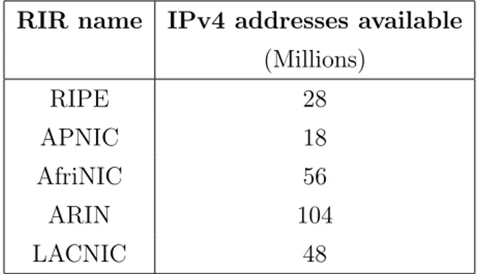
the statuses of the Regional Internet Registries (RIRs) is depicted in Table 1.1. This low availability of IPv4 addresses should be considered together
RIR name IPv4 addresses available (Millions) RIPE 28 APNIC 18 AfriNIC 56 ARIN 104 LACNIC 48
Table 1.1: IPv4 addresses available in late 2012 by all the RIRs
with the recent rise of the smartphone and tablet markets, because of those kind of devices are meant to be always connected, so they need addresses. This coincidence of events should bring Internet Service Providers (ISPs) and the Internet content delivery business to adopt IPv6 in the near future in order to keep customers satisfied. The risk is ISPs will use old fashioned solutions like the Network Addressing Translation (NAT) to slow down the
3August 2012
IPv6 transition, but surely this will be only a temporary fix and not a stable solution.
1.3
The actual adoption
Despite the lack of address availability from the RIRs the IPv6 protocol is used5 only by a small percentage of the Internet, but all the statistics show an impressive spike for the year 2012, as we can see in Figure 1.1 and Figure 1.2. The increment of IPv6 connections is related to many factors, like the
Figure 1.1: IPv6 traffic measured by Google in July 2012. The green line indicates native IPv6 connections.
IPv4 address exhaustion stated in Section 1.2, the mature IPv6 support from network vendors like CISCO and the recent World IPv6 Day6 supported by
Web giants like Google and Facebook.
5late 2012
6 1. Introduction to IPv6
Figure 1.2: IPv6 traffic measured by the RIPE RIR (July 2012)
1.4
Do I need IPv6?
The title of this section is one of the most recurrent networking question a company will ask to its IT team. The answer should be a straight Yes! but for the sake of clarity it is better to make some distinctions. The IPv4 address exhaustion concerns only public addresses, therefore an internal network is not going to run out of connectivity. Conversely the Internet services exposed by a company are going to receive IPv6 traffic during the next years because the RIRs will soon run out of IPv4 public connectivity (this scenario does not take into account awful NAT tricks by ISPs) and therefore the same will happen to ISPs. There will be neither a day for the IPv4/IPv6 switch nor one for an IPv4 shutdown, instead there will be a gradual migration to a dual stack solution and hopefully IPv4 will be dismissed definitely some day not too far. The key point is to actively embrace the IPv6 technology, investing
time and resources to gain knowledge and expertise in the field, instead of passively wait until it will be mandatory.
1.5
The protocol
The IPv6 protocol is not only a tool to provide more addresses, it is also an efficient redesign of IPv4, namely many improvements and desired features collected through the years by network engineers and architects. This section is not meant to be a complete technical presentation of IPv6, but a short list of key features that should give a quick summary of the importance of this new protocol (the interested reader is invited to consult the related RFC [11]).
1.5.1
A new addressing scheme
The first big change in IPv6 is the address length, that is four times longer than IPv4: 128 bits. The total number of available addresses is enormous, it will be possible to map thousands devices for each squared meter of Earth. This feature will definitely boost up the rise of the Internet of Things, namely the possibility to give an IP address to each electronic device equipped with sensors, even the things we use in everyday life: refrigerators, dishwashers, ovens, medical equipment, mp3 players and so on.
The IPv6 address is a lot different than IPv4 in several aspects: • each group of eight bits is represented in hexadecimal format; • each group of sixteen bits, called a nibble, is separated by a colon; • the leading zeros of a nibble could be omitted;
• multiple all zeros nibbles could be represented by two colons (::). Here are some examples:
8 1. Introduction to IPv6
• leading zeros omitted 2001:0:0:1:250:56ff:fe9a:72d5 • two nibbles shortened 2001::1:250:56ff:fe9a:72d5
The wary reader should follow this simple addressing exercise to convince himself about the enormous IPv6 address space:
• a company has received from the RIPE RIR a /48 subnet prefix for its network;
• following the best practice (see Section 1.5.5) it has reserved the last 64 bits to identify each host of its network;
• the company has now the possibility to use 16 bits to address its sub-nets, that is two to the power of 16 subsub-nets, 65536;
• moreover each subnet could address two to the power of 64 hosts, that is 18446744073709551616 hosts.
The reader is invited also to notice that in a /32 IPv6 address prefix the number of available subnets is equal to the actual public Internet address space.
1.5.2
One interface, multiple addresses
The original IPv4 stack had one constant: one physical interface manages only one IPv4 address. In the past years many operating systems like Linux and Windows implemented the so called IP aliasing, a technique able to handle multiple IPv4 addresses on the same interface emulating it through software. In the IPv6 world an interface could hold multiple addresses, each one having its scope in the network, implementing the IP aliasing concept directly in the protocol specifications.
There are two big families of IPv6 addresses, the unicast one and the mul-ticast one; in this paragraph we will analyze the former, whereas in Section 1.5.3 the latter.
Type Subnet prefix Scope Link Local fe80::/64 link Unique Local fd00::/8 cooperating sites
Global not fixed Internet
Table 1.2: Unicast IPv6 address types
As stated in Table 1.2 there are three types of unicast address: Link Local, Unique Local and Global. The first one is the entry point of the host to a network, because it is the address used to communicate through the link directly connected to the physical interface (it is auto generated using a reserved subnet prefix and the host identifier, either IEEE EUI-64 one or the random one, see Section 1.5.5). The Unique Local address is the IPv6 counterpart of the IPv4 private address7 whereas the Global address is an
Internet routable address. The reader is invited to notice how flexible is this solution, because it permits an interface to hold more than one address and to use them depending on its communication scope.
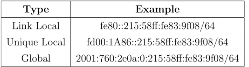
Type Example
Link Local fe80::215:58ff:fe83:9f08/64 Unique Local fd00:1A86::215:58ff:fe83:9f08/64
Global 2001:760:2e0a:0:215:58ff:fe83:9f08/64
Table 1.3: An example of three different IPv6 addresses for the same interface
Table 1.3 shows some examples of unicast addresses, the reader is invited to compare them with Table 1.2.
1.5.3
IPv6 multicast
A multicast address is an identifier related to a group of interfaces on hosts willing to receive the same set of IP packets. An host has to subscribe
7IPv4 Class A private address range 10.0.0.0/8, IPv4 Class B private address range
10 1. Introduction to IPv6
one of its interfaces to a multicast group in order to receive and send packets to a specific set of hosts, a more flexible solution compared to broadcasts. Multicast is an optional feature in IPv4, added through the years in order to implement some services efficiently. In IPv6 they are a first class passenger, it is used for all the vital network operations instead of broadcast.
Bits position 8 4 4 112 Address Bits FF 00PT scope group ID
Table 1.4: The IPv6 multicast address format
A multicast address follows the format stated in Table 1.4:
• the first eight bits are the fixed subnet prefix, namely ff00::/8;
• the second group of bits has two flags, P and T, respectively Prefix and Temporary. They indicate whether or not the multicast address has been built from an unicast subnet prefix or not and whether the address has been assigned permanently by IANA or not;
• the scope bits state the range of visibility for the multicast group. There are five relevant bits combination assigned by IANA: node-local, link-local, site-local, organization-local and global. This information is useful to routers in order to propagate properly the multicast packets to the appropriate set of hosts;
• the group id bits are user assigned, they are meant to identify a specific multicast host group.
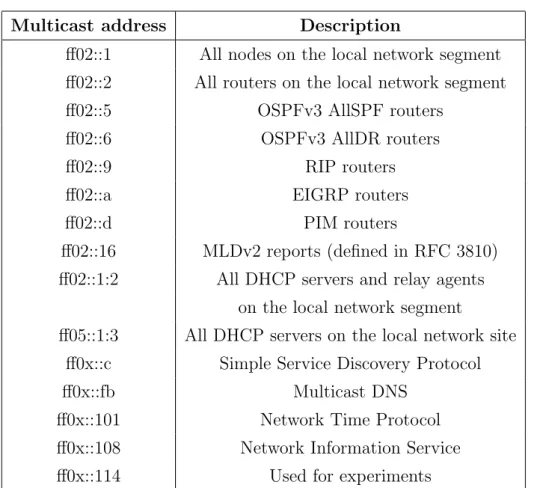
The IPv6 protocol involves multicast addresses for everything in order to avoid the use of expensive broadcasts, as we can see in Table 1.5. Multicast addresses are used also for supporting address autoconfiguration, as we are going to see in Section 1.5.5.
Multicast address Description
ff02::1 All nodes on the local network segment ff02::2 All routers on the local network segment ff02::5 OSPFv3 AllSPF routers
ff02::6 OSPFv3 AllDR routers ff02::9 RIP routers ff02::a EIGRP routers ff02::d PIM routers
ff02::16 MLDv2 reports (defined in RFC 3810) ff02::1:2 All DHCP servers and relay agents
on the local network segment
ff05::1:3 All DHCP servers on the local network site ff0x::c Simple Service Discovery Protocol ff0x::fb Multicast DNS
ff0x::101 Network Time Protocol ff0x::108 Network Information Service ff0x::114 Used for experiments
Table 1.5: List of known IPv6 multicast addresses created by IANA (from Wikipedia)
1.5.4
ICMPv6 and the Neighbor Discovery Protocol
The ICMP [25] protocol has been used in IPv4 networks mainly to di-agnose and test the connectivity between hosts, and a lot of vital tools like ping are based on its features, mainly the echo request/reply message types. The ICMPv6 [10] protocol has more responsibilities in IPv6, in fact it is the core of the Neighbor Discovery Protocol [22], the component responsible for: address autoconfiguration stateless autoconfiguration of the network
ad-dress, explained in detail in Section 1.5.5;
router discovery locating routers on the same link of the host;
12 1. Introduction to IPv6
2 address (essentially what ARP [24] does in IPv4);
duplicate address detection (DAD) discover whether or not an address is already in use;
reachability information (NUD) determine whether or not a node on the same link is reachable;
first hop redirect informing a node about a better first hop router (action performed by routers);
parameter discovery discovering of the link’s parameters like MTU8.
The Neighbor Discovery Protocol offers new services and re-implements some standard ones from IPv4, but it is important to understand that the big difference is in how it performs its actions: the NDP uses multicast instead of broadcasts if the underlying data link protocol supports it, easing the overall network load. For example suppose Node A wants to communicate to Node B, it holds its IPv6 address but it does not know the Ethernet MAC address. It then creates the Solicited Node multicast address of Node B appending to the reserved multicast prefix ff02:0:0:0:0:1:ff00::/104 the last 24 bits of the IPv6 address of Node B and finally it sends a Neighbor Solicitation to that address and waits for the answer from Node B. The IPv6 protocol specification states that every node in the network must join its Solicited Node multicast group during the startup of its network connection, otherwise nothing would work. This mechanism prevent the use of heavy broadcast each time an address resolution occurs and it is an elegant solution because it is independent from the underlying data link network, using ICMPv6 instead of knowing the broadcast address of the data link layer (ARP in fact must be implemented for each data link layer type, like Ethernet).
8Maximum transmission unit: size (in bytes) of the largest protocol data unit that the
1.5.5
Stateless Address Auto Configuration
As mentioned in Section 1.5.1 one of the best practices in IPv6 is to reserve the last 64 bits of the address to the so called host identifier, in order to use it for features like autoconfiguration, one of the major changes from IPv4. To understand properly the Stateless Address Auto Configuration it is mandatory to understand how a host generates a 64 bit sequence that should have the strong property to be globally unique. The starting point is the Ethernet MAC address, that is composed of 48 bits and should be unique for a particular physical interface (for the sake of clarity we don’t take into account interfaces belonging to Virtual Machines running on an Hypervisor, because obviously in this case the assumption is not true anymore). Subsequently if we add sixteen fixed bits to the MAC address we will obtain a globally unique host identifier. This procedure is the IEEE EUI-64 standard algorithm, this is a practical example of how it works:
• the starting point is an IEEE EUI-48 address, like 00:15:58:83:9f:08 • it is separated into two groups of bits: 001558 and 839f08
• they are joined together using the standard sequence of bits FFFF • the address is formatted as stated by the IPv6 protocol:
0015:58FF:FF83:9f08
Here comes the brand new IPv6 features, the address autoconfiguration. Routers will have more features in IPv6 networks, like the so called Router Advertisements, a new ICMPv6 kind of packet responsible to announce a subnet prefix to hosts connected to a specific network. Let’s go through an example: an host is connected to a network and it needs Internet connec-tivity. In IPv4 it has two possibilities: DHCP or manual configuration, that is someone tells the host which address to use. In IPv6 there is also the autoconfiguration option: if the host connected through the network receives a RA packet with a 64 bits subnet prefix it could generate a complete 128 bits IPv6 address using EUI-64, together with its default gateway, the router
14 1. Introduction to IPv6
responsible for the RA advertise. The DHCP is not so important anymore in IPv6 because of this new feature, that is meant to be not only an option but the standard.
Now we have more information to guess how a host boots up its network connection creating the link local address. As stated in Section 1.5.2 this kind of address is composed by a fixed subnet mask, namely fe80::/64, so a complete IPv6 address could be created appending the host identifier to the subnet mask. The same procedure is applied for the other types of unicast addresses, but in this case the host does not know the subnet prefix so it has to ask it to a third party source, the router.
1.5.6
IPv6 Header
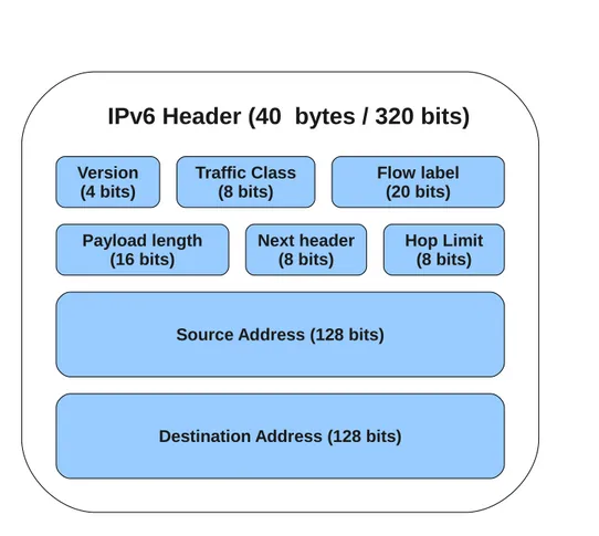
The IPv6 header is depicted in Figure 1.3, it has a fixed length of 40 octets (320 bits) and it contains some new features from IPv4. First of all we can notice the two 128 bits address fields for the source and the destination, as we said this imply potentially thousands of IPv6 addresses for each square meter of the Earth! Each field has its own purpose, here a brief review:
• Version - contains the number 6, the version of the IP protocol used • Traffic Class - a tag to assign different priorities to streams of packets • Flow Label - a label to identify packets belonging to the same flow • Payload length - self explanatory
• Next Header - the type of the next header, for instance the TCP or UDP (see Section 1.5.7 for a detailed introduction)
• Hop Limit - the equivalent of the TTL field in IPv4, namely the number of hops a packet could be forwarded by a node in the network • Source/Destination address - self explanatory
Traffic Class (8 bits) Flow label (20 bits) Payload length (16 bits) Version (4 bits) Hop Limit (8 bits) Next header (8 bits)
Source Address (128 bits)
Destination Address (128 bits)
IPv6 Header (40 bytes / 320 bits)
Figure 1.3: The IPv6 header fields
The IPv4 Checksum header field disappeared in IPv6, because the Layer 2 does the same work on frames. This change brings efficiency to routers that do not calculate anymore the checksum for each packet forwarded. Obviously the Layer 2 checksum will not spot Layer 3 router errors, but this will lead only to packet loss and retransmission due to common errors like address not existent and so on. Another header field disappeared is the IPv4 Options, but this will be addressed in Section 1.5.7.
16 1. Introduction to IPv6
1.5.7
IPv6 Extension Headers
The IPv4 header has a field called Options, a set of policies applied to the packet during its forwarding or to the end hosts participating to the communication. This field is not well designed for at least two reasons:
• efficiency - each time a router forwards an IPv4 packet it must read all the header fields, including the Options even if they concerns only end to end hosts;
• modularity - adding a new Options feature requires reserving a spe-cific bit sequence.
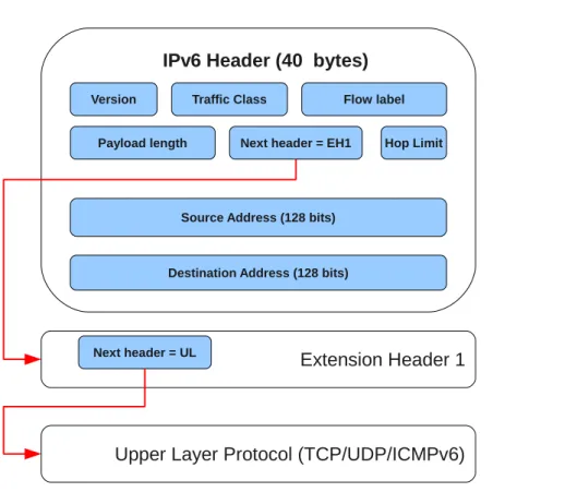
The IPv6 protocol has been designed to address the above problems using an elegant software engineering solution, namely pointer jumping. As we can see in Figure 1.4, the IPv6 header has a fixed length of 40 bytes and it does not contains any Options field. Instead the Next Header field states the type of the next header the packet contains after the main one. The next header could be an extension of the main IPv6 header or it could be an upper layer header, for example the TCP one. This design permits routers to focus only to the main header during the packet forwarding and the extensions only when requested, for example in case of ACLs. The commonly used extension header types are:
Hby-Hop EH used to supports Jumbograms [7] or to support the op-erations of the IPv6 Multicast Listener Discovery (MLD);
Fragmentation EH used to support communications of fragmented IPv6 packets (in fact in IPv6 the traffic source must perform fragmentation, routers only forwards packets);
Destination EH used in IPv6 Mobility as well as support of certain appli-cations.
The interested reader is invited to read the IPv6 RFC [11] for more informa-tion.
Traffic Class Flow label Payload length
Version
Hop Limit Next header = EH1
Source Address (128 bits)
Destination Address (128 bits)
IPv6 Header (40 bytes)
Extension Header 1
Next header = UL
Upper Layer Protocol (TCP/UDP/ICMPv6)
CINECA
“Dix,” Case said, ”I wanna have a look at an AI in Berne. Can you think of any reason not to?” The Neuromancer
2.1
The Italian University Consortium
CINECA1 is an Italian no profit consortium consisting of 54 Italian uni-versities2, the OGS3, the CNR4 and MIUR5; it is an high technology bridge among the academic world, the research, the industry and the public admin-istration. Its activities cover:
• the support to scientific research through supercomputing and its ap-plications, letting scientist to experiment the most recent HPC tech-nologies together with extensive expertise and user support.
• Management systems, services and technical-training support to uni-versity administrative offices. Since the 1980’s CINECA has supported Italian Universities in their main administrative areas like Students
1http://www.cineca.it
2by the time this thesis has been written, August 2012
3Istituto Nazionale di Oceanografia e Geofisica sperimentale, http://www.ogs.trieste.it/ 4Italian National Research Council, http://www.cnr.it
5the Italian Ministry for Education, University and Research, http://www.miur.it
20 2. CINECA
Management, Accounting and Human Relationships. This efforts led to the development of U-GOV6, adopted by a large number of Italian universities. Moreover CINECA founded KION7, a company focused on IT systems for student and learning services. This led to the develop-ment of another service called ESSE3, a Student Managedevelop-ment System, which has also been adopted from almost all the Italian universities. • Services for the Ministry of Education, University and Research.
CI-NECA manages most of the online services related to the MIUR, using the GARR8 network as communication infrastructure.
• Health Care Systems, more specifically the design and the development of IT systems and services in the health care and biomedical area, like various Web based system for the management of multicentric clinic trials and internal activities of various Health Care Organisations and scientific associations.
• Information and Knowledge Management Services, that is methods and techniques for the retrieval, management and analysis of data, infor-mation and knowledge.
2.2
The IT infrastructure
The CINECA infrastructure must support a wide range of services and technologies and above all it must be scalable and always efficient. The heart of such a big structure is obviously a reliable network, a keystone to build fast and strong Internet Web Applications.
The features of a well designed network should be the following:
• scalability - adding new subnets should be a straightforward operation and it must not slow down the rest of the preexisting environments;
6http://www.u-gov.eu 7http://www.kion.it
• reliability - link failures should not compromise the network function-ality;
• speed - the latency between hosts in the internal network or to the outside Internet should be as low as possible.
The CINECA network is mostly CISCO9based, at least in datacenter devices providing connectivity. It follows common best practices and some CISCO proprietary technologies to achieve the above design features. In the next subsections I will introduce the reader the most important best practices and CISCO add-on features used: Section 2.2.1 is about scalability and reliability in the network design, Section 2.2.2 is about managing the Data link layer efficiently, Section 2.2.4 is about network reliability and Section 2.2.5 is about the network traffic dispatching and separation. Finally Section 2.2.8 is about the CISCO Cloud Computing infrastructure adopted by CINECA.
2.2.1
Hierarchical Network Design
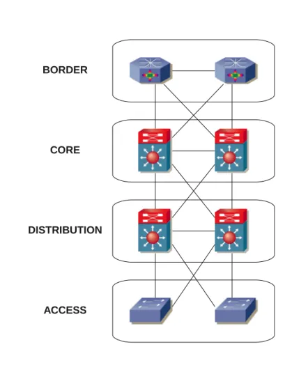
Networks design has evolved from flat to hierarchical topologies in order to let network architects to split functionality between layers to obtain mod-ularity and flexibility. A typical enterprise network should be organized in four layers, as illustrated in Figure 2.1:
• Access: provides direct connectivity to hosts.
• Distribution: provides routing to the access layer, implementing poli-cies for security and traffic loading, splitting networks into autonomous compartments.
• Core: implements the backbone of the network, a fast and redundant transport for the distribution layer.
• Border: provides the connectivity between the backbone and the In-ternet.
22 2. CINECA
CORE
ACCESS DISTRIBUTION
BORDER
Figure 2.1: The Hierarchical Network Design for an Enterprise
The principal benefits of this approach to networks design are the following: • scalability - network architects are allowed to replicate each module
apart from the others as the network grows;
• flexibility - changes to a specific layer does not require change the others, especially for security and traffic management;
• easier management and troubleshooting: there is a clear distinc-tion between Layer 2 switching and Layer 3 routing, that leads to more
efficients network operations performed by engineers;
• resiliency: this is the most important feature, because it guarantees multiple redundant paths in the network for the same data flow. As the reader may notice in Figure 2.1, each layer has more than one path for the same starting point of a communication, a link failure should not compromise the overall network availability.
The reader familiar with the hierarchical network design may skip to Section 2.2.6 to learn how it is implemented into the CINECA network infrastructure.
2.2.2
Virtual Local Area Network
A Virtual Local Area Network (VLAN) is a Layer 2 technology stan-dard [2] able to split the ports of a switch into multiple broadcast domains10 without requiring any additional hardware. Moreover multiple switches con-nected together may share the same broadcast domains using a special packet tagging called trunking.
Suppose you have a Layer 2 switch and ten hosts connected to it, each one sharing the same broadcast domain. If you need to split the hosts into two subsets, each one containing five hosts, you will have to buy another switch, surely not a flexible solution. If the switch supports Virtual LANs you would simply create two separate broadcast domain called, for example, A and B, each one managing only the ports of the switch connected to its assigned subset of hosts. The VLAN A and VLAN B will communicate using the Layer 3 IP protocol, namely a router will join them.
A slightly more complicated example is the following: suppose you have two Layer 2 switches, ten hosts connected to each one and the same prob-lem above, namely separate the total twenty hosts into two broadcast do-mains without rearranging the connection between hosts and ports. The two switches would be connected by a link used to exchange frames between
10A broadcast domain is a logical division of a computer network, in which all nodes
24 2. CINECA
hosts of the same VLANs; each port would be tagged as host or trunk : the former indicates a direct connections to a host, the latter a connection be-tween switches. The two ports connected to the trunk link must perform the additional work to tag each frame they send by its VLAN ID in order to keep the broadcast domains separated. This technique is called trunking and it is the standard that permits multiple switches to share the same set of VLANs.
2.2.3
Mapping VLANs to IP subnets
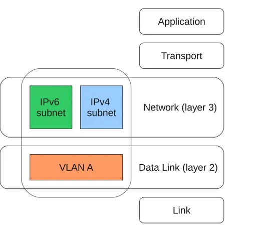
As stated in Section 2.2.2, two hosts belonging to different VLANs can communicate only through the IP Layer, therefore a mapping between VLANs and IP subnets is needed at this point. Let’s go through an example: suppose to have a set of hosts connected to one or more Layer 2 switches, sharing the same broadcast domain and you need to split the network into two set of hosts, assigning to each set an IP subnet. The first thing to do is creating two broadcast domains using VLANs, for example calling them A and B, and then assign each one to an IP subnet. In our example we could map two IPv4 class C subnets to VLANs in the following way:
• VLAN A 192.168.4.0/24 • VLAN B 192.168.5.0/24
Finally a router must be connected to the switches in order to enable the IP routing. The router must have at least two interfaces (physical o virtual), one holding an IP address belonging to the range assigned to VLAN A and the other holding an IP address belonging to the range assigned to VLAN B (for example 192.168.4.1 and 192.168.5.1). The mapping between the VLANs and the IP subnets, two separate concepts belonging to separates Internet Layers, is achieved setting each interface of the router to its correspondent assigned VLAN. This is a simple operation available in all the recent router equipment, in fact CISCO implements it into its IOS operating system. A
graphical explanation of the differences between Layer 2 and Layer 3 concepts is depicted in Figure 2.2.
Data Link (layer 2)
Transport
Network (layer 3)
Link
IPv4
subnet
IPv6
subnet
VLAN A
Application
Figure 2.2: Example: mapping a VLAN to its correspondent IPv4/IPv6 subnets
2.2.4
CISCO Hot Standby Router Protocol
The Hot Standby Router Protocol (HSRP) is a CISCO proprietary pro-tocol for managing redundant and fault tolerant default gateways assigned to IP subnets. This protocol is implemented often in the Distribution layer, where each IP subnet needs some redundancy in order to prevent losing con-nectivity due to a link failure. The protocol lets two routers share a virtual IP
26 2. CINECA
address and a virtual MAC address, acting as a unique virtual router. They communicate with each other sending hello messages through IP multicast-ing in order to establish which one of them will answer to ARP/Neighbour Discovery11 requests. One of the two routers needs to be set to Active while
the other to Standby as starting point, and once a failure to the Active router occurs the other one will step in taking the place of the other one, transparently to the hosts of its IP subnet.
2.2.5
CISCO Virtual Router and Forwarding
The Virtual Routing and Forwarding technology permits to maintain two or more routing table instances on a single physical router, in order to sep-arate traffic allowing the creation of virtual circuits for datagrams. This technology is useful when network engineers are requested to track and sep-arate network traffic based on a set of rules. From an external point of view a VRF instance is a logical router completely separated from the other ones, although sharing the same hardware. For example, separate VRF instances can use the same IP subnet without conflicts; ISPs use this technology to implement Virtual Private Networks for customers using the same hardware without the need to use encrypted data channels, saving a lot of money buying less hardware. The network infrastructure of a datacenter could be implemented using a set of routers each one configured with the same set of VRF rules, allowing multiple clients to share the same hardware without conflicts or security flaws. Section 2.2.7 explains in detail how this technique is used to separate the network traffic in the CINECA network.
2.2.6
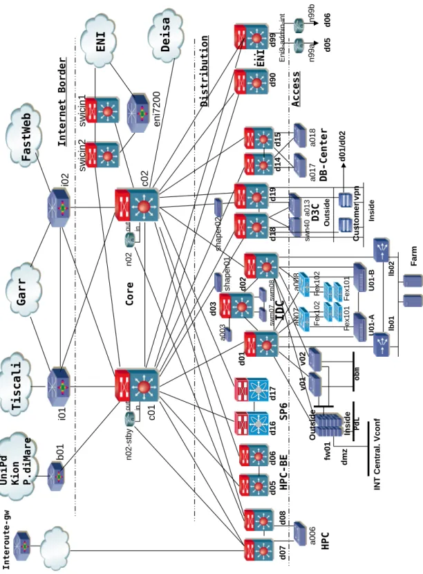
The CINECA Network Design
The CINECA network design follows all the best practices illustrated in the previous sections, as the reader can see in Figure 2.3. The picture may seem a little bit confusing and sketchy, but a closer look reveals that it follows
the hierarchical design principles illustrated in Section 2.2.1. Let’s examine each network layer more accurately:
Internet Border This is the boundary between the internal network and the Internet, it must be a fast gateway and the first line of protection against malicious attacks at the same time. It is composed of routers, their first responsibility is to communicate with other routers through the Border Gateway Protocol [26] in order to establish dynamic routes to the Internet. CINECA uses a combination of peering agreement with third parties and announcements of its Internet prefixes from Provider Dependent and Independent sources. More specifically the b01 router implements peering with the University of Padua, Kion and P.diMare, whereas i01 and i02 are directly connected to a GARR router for the academic traffic, and to Tiscali and Fastweb for commercial traffic. Core The c01 and c02 routers are the backbone of the entire network, they
dispatch all the traffic within the internal network and towards the Border layer. They do not implement any sort of filtering or security checks on datagrams, instead they offer a solid, redundant and fast service. The two routers use the OSPF routing protocol to dynamically find the best routes to reach the lower Distribution layer and the upper Border layer.
Distribution This layer does the real segmentation of the network, it splits all the traffic between separate compartments to different VLANs. As the reader may notice there are segments for the High Performance Computing systems, for the employees hosts, for the Production envi-ronments like clusters and farms, for the Virtual Private Networks for guests and for the Database hosts. Each segment communicates with the other ones through two routers implementing the HRSP CISCO technology (please see Section 2.2.4 for more details) in order to guar-antee redundancy and resilience. The routers communicate through the OSPF routing protocol, announcing their subnets to the Core layer.
28 2. CINECA G a r r T i s c a l i F a s t W e b H P C H P C -B E d0 8 d0 7 d0 1 i0 1 d1 9 d9 0 d0 3 d0 2 d0 5 d0 6 I D C . . . d9 9 d1 8 d1 7 d1 6 D 3 C S P 6 E N I i0 2 c0 2 c0 1 Fa rm P d L fw 01 lb01 lb02 I n t e r n e t B o r d e r C o r e D i s t r i b u t i o n b0 1 U n i P d K i o n P . d i M a r e E N I sw ici n2 sw ici n1 en i7 20 0 d1 4 d1 5 D B -C e n t e r a0 17 a0 18 D e i s a a0 06 I n t e r o u t e -g w sw n4 0 a0 13 sh ap er 01 sh ap er 0 2 Ins ide O ut si de dmz IN T C en tra l. V conf v 01 ob m C u st o m e r v pn Insid e Outs ide d0 1/ d0 2 v 0 2 Fe x10 1 a0 03 sw m 0 7 sw m 0 8 n0 2-st by n0 2 ou t ou t in in a0 07 a0 08 Fex 1 02 Fex 1 02 Fe x10 1 A c c e s s U01-A U01-B n9 9a n9 9b d0 5 d0 6 Eni9 -ad mi n-i nt
Access This layer directly connects hosts to switches, it implements the VLAN segmentation and it joins them to their related Layer 3 IP sub-nets using the technique explained in Section 2.2.3.
The main difference from the scheme depicted in Figure 2.1 are the link connections between the Core and the Distribution layers: each distribution router is not strongly connected to the two core routers. The reason is the cost: each link between Distribution and Core is 10 Gigabit fiber, therefore it costs a lot in term of ports available on the routers and connection ca-bles. Redundancy is achieved through the HSRP, each Distribution router monitors the availability of its links, and whenever one of them fails it will automatically decrease its HSRP priority (see Section 2.2.4) forcing the net-work data flow through the other Distribution router, therefore bypassing completely the failed link. Obviously this is a trade off, it does not achieve all the redundancy of a complete hierarchical design but it does guarantee a strong resiliency. Moreover the bandwidth between Distribution and Core is big enough to tolerate one link failure, whereas multiple ones could compro-mise the network availability.
2.2.7
The CINECA Autonomous Systems
CINECA is a consortium of universities, it offers Internet services and web hosting to third parties, so it needs some network traffic separation policies to maintain more efficiently its large infrastructure. In particular there are two big traffic categories flowing in and out the CINECA network:
• Academic traffic • Commercial traffic
The Academic network traffic is generated from the Internet Services used by Italian universities and HPC community, it is managed though the GARR network and it has some traffic load policies. The Commercial traffic is asso-ciated to Internet Services and web hosting for the Private market, and it is
30 2. CINECA
managed through the Fastweb and Tiscali networks. The naive solution to keep the network traffic separated could be to physically duplicate the net-work equipment into two Autonomous Systems and then connect them using a routing protocol like BGP. This solution is feasible for small enterprises, but it is clear that it is not scalable for medium and large infrastructures. As stated in Section 2.2.5 CISCO offers a technology called Virtual Routing and Forwarding to keep different routing table instances on the same network component, so it is feasible and easy to keep different logical infrastructures on the same physical hardware. It is now straightforward to guess how CI-NECA has implemented the network traffic separation: creating one VRF for the Academic traffic and another one for the Commercial traffic. More-over each logical infrastructure created through a VRF is then associated to a separate Autonomous System ID. The WHOIS RIPE database is a good tool to investigate how the assigned IP subnets have been associated to dif-ferent AS IDs. Let’s start with the Academic VRF: it has been assigned to the IPv4 subnet 130.186.0.0/19 with assigned AS ID AS137, as the reader can see in Figure 2.4. A subsequent query to the Ripe Database for more information about the AS ID found shows us that the ID belongs to GARR (see Figure 2.7), in fact the subnet 130.186.0.0/19 is Provider Dependent, namely GARR act as Local Internet Registry for CINECA. This means that the real AS ID associated with the IPv4 subnet is private to GARR. Con-versely the IPv4 subnet 130.186.64.0/18 is assigned to the AS ID AS3275 (see Figure 2.5), that is Provider Independent because of it comes directly from the RIPE RIR, as stated in Figure 2.6.
All the Autonomous Systems IDs stated above are related only to IPv4 sub-nets, but it is easy to extend them with IPv6 subnets; this let CINECA to skip the request for other AS IDs to the related autorities.
inetnum: 130.186.0.0 - 130.186.31.255 netname: CINECA-NET
descr: Consorzio di Calcolo Interuniversitario CINECA country: IT
admin-c: ADF16-RIPE tech-c: AA107
status: ASSIGNED PI
remarks: GARR - Italian academic and research network mnt-irt: IRT-GARR-CERT
mnt-by: GARR-LIR
source: RIPE #Filtered
route: 130.186.0.0/19 descr: CINECA-NET origin: AS137 remarks: CINECA mnt-by: GARR-LIR
source: RIPE #Filtered
Figure 2.4: The result of a WHOIS query submitted to the RIPE Database for the subnet 130.186.0.0/19 (August 2012)
32 2. CINECA inetnum: 130.186.64.0 - 130.186.127.255 netname: CINECA-NON-GARR-NET descr: CINECA-NON-GARR country: IT admin-c: ADF1-RIPE tech-c: AA107 status: ASSIGNED PI
remarks: CINECA - Connettivita’ Non Garr mnt-by: CINECA-MNT
source: RIPE #Filtered
route: 130.186.64.0/18 descr: CINECA-NON-GARR origin: AS3275
remarks: CINECA - Connettivita’ Non Garr mnt-by: CINECA-MNT
source: RIPE #Filtered
Figure 2.5: The result of a WHOIS query submitted to the RIPE Database for the subnet 130.186.64.0/18 (August 2012)
as-block: AS3209 - AS3353 descr: RIPE NCC ASN block org: ORG-NCC1-RIPE admin-c: CREW-RIPE tech-c: RD132-RIPE mnt-by: RIPE-DBM-MNT mnt-lower: RIPE-NCC-HM-MNT source: RIPE #Filtered
aut-num: AS3275 as-name: ASN-CINECA
descr: CINECA multi-homed Autonomous System
Figure 2.6: The result of a WHOIS query submitted to the RIPE Database for the AS3275 (August 2012)
34 2. CINECA
as-block: AS137 - AS137 descr: RIPE NCC ASN block org: ORG-NCC1-RIPE admin-c: CREW-RIPE tech-c: RD132-RIPE mnt-by: RIPE-DBM-MNT mnt-lower: RIPE-NCC-HM-MNT source: RIPE #Filtered
aut-num: AS137 as-name: ASGARR
descr: GARR Italian academic and research network source: RIPE #Filtered
role: GARR LIR
address: Consortium GARR address: Via dei Tizii, 6 address: I-00185 Roma address: Italy
Figure 2.7: The result of a WHOIS query submitted to the RIPE Database for the AS137 (August 2012)
2.2.8
CISCO Unified Computing System
The CISCO Unified Computing System12(UCS) is a CISCO and VMWare13 joint product that represent a flexible enterprise solution to build small and medium size Private Clouds14. The Wikipedia’s definition15 is more general:
The CISCO Unified Computing System (UCS) is an x86 ar-chitecture data center server platform composed of computing hardware, virtualization support, switching fabric, and manage-ment software. The idea behind the system is to reduce total cost of ownership and improve scalability by integrating the different components into a cohesive platform that can be managed as a single unit.
The UCS deployed at CINECA is composed of the following components, as the reader can see in Figure 2.8:
• D01 and D02 routers - see Section 2.2.6;
• a007 and a008 switches - see Section 2.2.6;
• UCS 6120 XP Fabric Interconnect - 10G switches, they provide connectivity to the UCS’s blade servers and the storage units using the Fibre Channel protocol over Ethernet;
• UCS 6508 Blade servers - CISCO blade servers;
• UCS Storage - the storage hardware components.
12
http://www.cisco.com/en/US/products/ps10265/technology.html
13http://www.vmware.com
14Private cloud is cloud infrastructure operated solely for a single organization, whether
managed internally or by a third-party and hosted internally or externally, Wikipedia, August 2012
15http://en.wikipedia.org/wiki/Cisco_Unified_Computing_System, Wikipedia,
36 2. CINECA UCS 6508 Chassis Model ESX 1-8 UCS 6508 Chassis Model ESX 9-16 D01 D02 a007 a008 UCS 6120XP Fabric Interconnect UCS 6120XP Fabric Interconnect Nexus 5020 WS-6509-E Storage Storage
Figure 2.8: The network design for the CINECA UCS
This solution permits to deploy new hosts though virtual machines and connect them to a specific VLAN/IP subnet (as we said in Section 2.2.3 the two concepts overlaps) without requiring new hardware and networking components, obviously consistently with the maximum capacity of the UCS.
Towards a migration strategy
The work plan
Everything should be made as simple as possible, but not simpler. Albert Einstein
A well designed work plan should come after a study of the requirements followed by an analysis of the available tools and best practices. It should be clear that whatever the solution to the problem is, it will never be the panacea of the subject but only a complete working solution for the specific case analyzed. This is why the reader, before going any further, should read carefully all the motivations and details about our work plan.
This chapter is organized as follows: Section 3.1 collects the initial re-quirements for the migration, Section 3.2 shows a collection of solutions for different migration strategies and Section 3.3 states the complete work plan together with its main milestones.
3.1
Initial requirements
As stated in Chapter 2, the CINECA focus is to deliver reliable and efficient Internet Services. The keystone is changing the running IT infras-tructure without interfering with the customers, in order to guarantee a pro-ductive interaction with the CINECA services. This is like replacing a gear to the engine of a running car: engineers can not stop and start the running
40 3. The work plan
tems to check correct configurations as they wish. The new features applied to a system must be tested into a separate environment from production, in order to apply once all the required changes affecting as little as possible the services continuity. The second big requirement is performing changes to the infrastructure without altering the user perception of the legacy software stacks, like incremented latency and less availability. Last but not the least, all the CINECA employee should keep working to their projects without any change in the network and Internet availability.
3.2
Migration strategies and solutions
The challenging part during the moving to a different addressing proto-col is the need to work on each layer of the stack, because everything will be affected. The network layer obviously is the one requiring most of the attentions, but we should not forget about the application layer. The first thing the reader may think is: Why would you do that? The Internet stack is designed to prevent this kind of problems, so it should be fine to migrate an application from IPv4 to IPv6 without changing a line of code! Partially true, there are coding details to address properly in order to prevent application issues.
In this Section are grouped the most common best practices and avail-able tools required to deal with the IPv6 migration with the requirements stated in Section 3.1. Section 3.2.6 presents the most common Application level problems, Sections 3.2.1 is about Network Address Translation and IP Tunnelling, Section 3.2.2 is about how organize and manage the migration, Section 3.2.5 is about the DNS changes required, Section 3.2.3 is about the Addressing Plan and Section 3.2.4 is about the necessary network security precautions to apply before going into production.
3.2.1
Transition to IPv6: Dual Stack, NAT IPv6 to
IPv4 and IPv6 Tunnelling
Network Address Translation is a well established technique used in IPv4 to let private networks communicate with public ones saving precious public IPv4 addresses, using one public IP as multiplexer for multiple communica-tions between hosts in the private network and the other hosts outside. The most advertised feature of IPv6 is the enormous address space, every device with a network interface will have a public Internet address in the near future, so why should we talk about NAT and IPv6? Imagine a scenario in which an enterprise network is segmented into IPv6 only and IPv4 only subnet islands: the latter could contain legacy hosts running old applications not designed for IPv6, whereas the former could contain hosts running applications on an IPv6 only environment in order to find issues with the new network stack before going into production. In this case network engineers need a tool able to translate the addresses from IPv6 to IPv4 and vice-versa transparently to the higher protocols. In this section we will analyze the NAT64[18][4] translation mechanism, focusing on connecting IPv6 only islands to the IPv4 Internet, as depicted in the example of Figure 3.1.
The NAT64 is a technique able to translate IPv6 headers to IPv4 ones, usually performed by a router managing an IPv6 subnet. There are two main type of NAT64:
Stateless The NAT64 router performs a one to one mapping between an IPv6 address in its subnet and an IPv4 one, usually embedding it into the IPv6 address through the use of specific algorithms (for more in-formation please consult [18]). This approach scales very well because it does not keep connection states but its main drawback is the need of one separate IPv4 address for each IPv6. This means Stateless NAT64 can not be used in context in which the IPv4 address are few, like the actual IPv4 address exhaustion.
42 3. The work plan NAT64 Router Node A (IPv6 only) Node B (IPv6 only) DNS 64 Server IPv4 IPv6
Figure 3.1: An example of NAT64 deployment
IPv4, but in this case it needs to keep the state of each ongoing con-nection as it happens today in NAT44[27]. This permits to have only one IPv4 address mapping an entire IPv6 subnet, but the drawback is that only an IPv6 host inside the subnet could establish a connection to an IPv4 host outside and not the opposite.
Moreover both of the above solutions must implement a third-party mecha-nism to translate DNS requests from the IPv6 world to the IPv4 world: in fact an IPv6 only subnet could make DNS requests for not existent AAAA records in the IPv4 cloud outside the NAT. The DNS 64[5] is a DNS res-olution mechanism coupled with NAT64: it translates the AAAA record requests for a particular domain to the appropriate A record if the domain does not support IPv6, then it embeds the IPv4 address into an IPv6 one and returns it to the requestor. Let’s go through a simple example, the one depicted in Figure 3.1: two IPv6 hosts behind a stateful NAT64 router. Suppose the following global IPv6 prefix as been assigned to the company owning the hosts: 2001:760::/32. The network engineers could assign the prefix 2001:760:1:a:b:c::/96 to the NAT64 router, the IPv6 hosts will be manually configured with the addresses:
• Host A - 2001:760:1:a:b:c::1 • Host A - 2001:760:1:a:b:c::2
The DNS64 server and the NAT64 router would be configured as stated in Table 3.1, in dual stack IPv4/IPv6 mode in order to glue together the two protocols in the network.
Host IPv6 address IPv4 address Router NAT64 2001:760:1:a:b:c::42 192.168.2.42
Server DNS64 2001:760:1:a:b:c::43 192.168.2.43
Table 3.1: Configuration example for a simple NAT64 deployment
An example of the TCP starting step initiated by Host A is depicted in Figure 3.2. As the reader may notice the keystone of the entire process is the trick used by the DNS64 server to embed an IPv4 address into an IPv6, that is appending to the tail of the IPv6 /96 network prefix the IPv4 address associated with the A record of the domain example.com.
Tunneling IPv6 into IPv4 is a technique able to encapsulate IPv6 packets into IPv4 ones, in order to join IPv6 subnets through an IPv4 path. This is really useful during the transition between the two protocols, because it permits to use IPv6 without the need to deploy it to the entire network. Imagine a company with multiple sites, each one experimenting the IPv6 protocol enabling the dual stack IPv4/IPv6 on a subset of hosts: it would be great to let them communicate through the IPv6 protocol without requiring to upgrade the entire network, using the pre-existing IPv4 transport. The most common suggestion is to use this kind of tunnels only during the start up phase of the migration if needed, because they are not contemplating by the IPv6 best practices as a permanent solution.
There are three main types of IPv6 to IPv4 tunnels: 6to4[8], ISATAP[28], Teredo[16].
In 6to4 each IPv4 globally routable address is used to build a unique IPv6 /48 subnet with prefix 2002::/16 appending the hexadecimal version of the
44 3. The work plan NAT64 2001:760:1:a:b:c::42 192.168.2.42 DNS64 2001:760:1:a:b:c::43 192.168.2.43 IPv4 Cloud AAAA record example.com Record not found
Host A 2001:760:1:a:b:c::1 AAAA record example.com A record example.com 2001:760:1:a:b:c:1111 TCP SYN 2001:760:1:a:b:c:1111 TCP SYN 1.1.1.1 1.1.1.1 SYN ACK 192.168.2.42 SYN ACK 2001:760:1:a:b:c:1111
Figure 3.2: Example of a NAT64 scenario
32 bits IPv4 address to the reserved 16 bits prefix, this should guarantee the uniqueness of the 48 bits IPv6 prefix. Subsequently it would be possible to use the prefix to create different subnets or to build a complete IPv6 128 bits address, depending if there is the need to provide IPv6 connectivity to a group of hosts or only to one host. The typical use case is the deploy of 6to4 to two routers (the endpoints) holding each one an IPv4 global address in order to obtain two IPv6 /48 prefix and supplying IPv6 connectivity to the hosts they manage. This tunnelling technique needs also the presence of a well known relay in the outside Internet to work properly, the 6to4
RFC states that the IPv4 anycast address 192.88.99.1 and the IPv6 address 2002:c058:6301:: have been reserved by IANA for this purpose. A simple example of a 6to4 deployment is depicted in Figure 3.3. The reader should not confuse the 6to4 tunnelling technique with the 6in4[23] one, they share most of the implementation details but the former is more general and flexible respect to the latter.
6to4 Router IPv4 130.186.1.1 IPv6 2002:82BA:0101::1 IPv4 IPv4 6to4 Router IPv4 130.136.2.1 IPv6 2002:8288:0201::1 6to4 Relay IPv4 192.88.99.1 IPv6 2002:c058:6301:: Host A IPv4 130.186.1.2 IPv6 2002:82BA:0101::2 Host B IPv4 130.186.1.3
IPv6 2002:82BA:0101::3 Host C
IPv4 130.136.2.2 IPv6 2002:8288:0201::2
Host D
IPv4 130.136.2.3 IPv6 2002:8288:0201::3
Figure 3.3: Example of a 6to4 deployment scenario
The Intra-Site Automatic Tunnel Addressing Protocol (ISATAP) lets dual-stacked (IPv6/IPv4) nodes to communicate using the IPv6 protocol where the protocol is not directly supported from the network infrastructure, using the IPv4 protocol as non multicast/broadcast capable link layer for IPv6. This technique permits automatic tunnelling from IPv6 to IPv4 and it works
46 3. The work plan
whether or not global IPv4 address are used. Using IPv4 as non multicast link layer interfere with IPv6 features like the Router Discovery, therefore ISATAP needs some external tools to work properly. For example in order to retrieve the list of available ISATAP relay routers it usually makes a query to the DNS name server configured with domain like isatap.domain.com, where domain is the local domain name. The major criticism about ISATAP is the need to have some support from Upper layer protocols like the DNS violating the Internet Stack principles.
Both 6to4 and ISATAP insert the IPv6 packet right after the IPv4 header setting the protocol type with the value 41, the reserved number indicating the presence of a tunnelling from IPv6 to IPv4. This technique is really efficient and offers a little overhead, but if an host is behind a NAT44 the tunnel will not work because it is not supported by the network translation mechanism (a host behind a NAT44 holds a private IPv4 address, not a global one as requested by the tunnelling protocols). Teredo offers a solution to the problem encapsulating the IPv6 packets into IPv4 UDP ones, thus relying on a transport protocol to establish a tunnel between IPv6 capable hosts. It needs a registration server holding a global IPv4 address and routers acting as relays to manage the connection between the source and the destination hosts: in this way both hosts can communicate behind NATs or symmetric firewalls without any connection problems. The hosts using a Teredo tunnel will build an IPv6 address starting with the prefix 2001::/32 combining it with the hexadecimal version of the Teredo server’s IPv4 address and the NAT44’s IPv4 address, the complete algorithm is described in detail into the Teredo’s RFC. A Teredo deployment example is depicted in Figure 3.4 (example taken from [15]).
3.2.2
Top Down vs. Bottom Up
The most difficult thing to do before every big change is to choose where to begin. There are two main approaches in the networking world: top down and bottom up. The former is the optimistic one, it starts from the
Teredo Relay IPv4 Internet IPv6 host 2001:760:2e0a:1::5 Teredo Client IPv4 192.168.2.2 IPv6 2001:0:53aa:64c:0:78f8:ae0f:22f9 IPv4 Intranet IPv4 NAT IPv4 192.168.2.1 IPv4 81.240.221.6 IPv6 Internet Teredo Server IPv4 83.170.6.76
Figure 3.4: Example of a Teredo deployment scenario
network’s backbone, where the Core routers work, enabling IPv6 using an interior routing protocol like OSPF. The Core is designed to be the skeleton of the network, it must be as fast as possible: it does not need security filters or packet inspection because this could lead to an overall network slowdown. Security is implemented in the Border layer and in the Distribution one, so the Core theoretically would be an optimum starting point for a migration to IPv6. Subsequently the upgrades should reach the Distribution layer, then the Access layer and finally the Border. This approach has the drawback to change a vital part of the network that could potentially create some net-work outages, so it is not recommended in the CINECA case of study (the reader should have read the migration requirements stated in Section 3.1). Moreover all the Internet services would be tested in the last part of the