Alma Mater Studiorum · Università di Bologna
SCHOOL OF ENGINEERING AND ARCHITECTURE
Department of Electrical, Electronic and Information Engineering
DEI
"Guglielmo Marconi"
Second Cycle Degree
in
Telecommunications Engineering
Software Defined Radio for NB-IoT
Master Thesis in Radio Systems
Candidate:
Michele Paffetti
Supervisor:
Chiar.mo Prof. Ing.
Roberto Verdone
Co-Supervisor:
Prof. Ing. Raymond Knopp
Academic Year 2016/2017 Session II
Abstract
The next generation of mobile radio systems is expected to providing wireless connectivity for a wide range of new applications and services involving not only people but also machines and objects. Within few years, billions of low-cost and low-complexity devices and sensors will be connected to the Internet, forming a converged ecosystem called Internet of Things (IoT). As a result, in 2016, 3GPP standardizes NB-IoT, the new narrowband radio technol-ogy developed for the IoT market. Massive connectivity, reduced UE complexity, coverage extension and deployment flexibility are the targets for this new radio interface, which also ensures harmonious coexistence with current GSM, GPRS and LTE systems. In parallel, the rise of open-source software combined with Software Defined Radio (SDR) solutions has com-pletely changed radio systems engineering in the late years. These platforms provide testbed for experimental analysis and prototype development enabling researchers to test, validate and assess the performance of new technologies for wireless networks. This thesis focuses on developing the NB-IoT’s protocol stack on the EURECOM’s open-source software platform OpenAirInterface (OAI). First part of this work aims to implement NB-IoT’s Radio Resource Control functionalities on OAI. After an introduction to the platform architecture, a new RRC layer code structure and related interfaces are defined, along with a new approach for Signalling Radio Bearers management. A deep analysis on System Information scheduling is conducted and a subframe-based transmission scheme is then proposed. The last part of this thesis addresses the implementation of a multi-vendor platform interface based on Small Cell Forum’s Functional Application Platform Interface (FAPI) standard. A configurable and dy-namically loadable Interface Module (IF-Module) is designed between OAI’s MAC and PHY layers. Primitives and related code structures are presented as well as corresponding Data and Configuration’s procedures. Finally, the convergence of both NB-IoT and FAPI require-ments lead to re-design PHY layer mechanisms for which a downlink transmission scheme is proposed.
This work constitutes a precious starting point to ensure OpenAirInterface interoperability, flexibility and IoT capabilities to face the next generation of mobile radio technology.
This Master thesis project is conducted in collaboration with the Communication Systems Department of EURECOM, a France research institute based in Sophia Antipolis.
Acknowledgement
Vorrei sfruttare queste righe per fare dei ringraziamenti che credo riassumano un po’ quello che sono oggi.
Innanzitutto, se sono arrivato fin qui, è perchè mi è stato concesso da Dio, in cui credo. Pertanto, oggi come ogni giorno lo ringrazio per donarmi questa vita piena di amore, bellezza, fatica, errori e felicità.
Un sentito ringraziamento va al Professor Roberto Verdone, relatore di questa tesi. Ringrazio il professore per aver riposto in me una grande fiducia, dandomi l’opportunità di svolgere questo progetto in un contesto di altissimo livello nel campo delle telecomunicazioni. Il tirocinio ad EURECOM mi ha reso più consapevole dei miei mezzi e sarà un esperienza che porterò sempre con me.
Ringrazio dal profondo del cuore la mia famiglia, a cui dedico questa tesi. Ringrazio i miei genitori, per i sacrifici che hanno fatto e fanno ogni giorno per me; mi hanno dato l’opportunità di arrivare dove sono oggi senza farmi mancare niente. Rigrazio i miei fratelli, Chiara e Gabriele, che riempiono le mie giornate tristi con sorrisi e amore; spero di poter essere sempre per loro un esempio da seguire. Ringrazio poi la mia ragazza Flora per tutte quei giorni, quelle settimane, quei mesi che ha sopportato la mia lontananza. Sono convinto che nessun’altra avrebbe fatto lo stesso in tutti questi anni e questo dimostra quanto lei tenga a me. Spero di poter ripagare con il mio amore tutto quello che mi ha dato e continua a darmi ogni giorno. Ringrazio gli amici di una vita, quelli della palla a spicchi e quelli dell’Agazzi Cleb che seppur in questi ultimi anni ci vediamo veramente poco, sono sempre lì, pronti ad accogliermi per organizzare qualche cena o intraprendere insieme una nuova avventura. Un ringraziamento speciale va al mio amico «Relly», ormai ho perso il conto da quanti anni ci conosciamo. Lui c’è sempre quando «gna fare du sgassate» e in questo ultimo periodo ha pazientemente aspettato il mio ritorno in pista (gasse a manetta ora). Ringrazio poi il nostro (mio e di Albe) amico di merende PowerCorte, che in questi due anni ha fatto passi da gigante grazie alla mia assidua presenza; mi ha insegnato che a volte nella vita bisogna essere un po’ più «scialli». Infine, ma non per importanza, ringrazio i compagni di viaggio Magjar; seppur per molti di noi le strade si sono divise, so che ognuno potrà sempre contare sull’aiuto degli altri. Questa nostra amicizia è per me qualcosa di veramente importante che porterò sempre nel cuore.
I would hereby like to express my gratitude and appreciation to Prof. Raymond Knopp, my supervisor at EURECOM, for having followed me during my Internship and put me in contact with the OSA reality. Moreover, I express my gratitude to anyone in EURECOM who helped and made me possible to successfully complete my Internship: Prof. Navid Nikaein, for his precious advices on approach OAI’s RRC code; Younes Khadraoui, who was the first person to welcome me on my arrival; Cedric Roux, who endured me every time I asked him help on programming; Shahab Shariat, for our talks on the world of research. Last, but not least, I would like to thank my Internship companion Nick Ho, in the three months we worked side by side he taught me much and we had a lot of fun together.
Contents
Abstract iii Acknowledgement v 1 Introduction 1 1.1 Objectives . . . 2 1.2 Outline . . . 3 2 Background 5 2.1 Towards IoT . . . 5 2.1.1 Introduction . . . 52.1.2 LTE Evolution towards IoT: eMTC and NB-IoT . . . 6
2.2 Software Defined Radio . . . 8
2.3 OpenAirInterface . . . 9
2.3.1 Introduction . . . 9
2.3.2 Platform Architecture . . . 9
2.3.3 The Alliance Project: Narrowband Internet of Things . . . 11
2.4 Abstract Syntax Notation . . . 12
2.5 Narrowband Internet of Things (NB-IoT) . . . 13
2.5.1 Network Architecture . . . 13
2.5.2 NB-IoT Radio Protocol Architecture . . . 14
2.5.3 PHY . . . 15
2.5.4 RRC . . . 19
3 Small Cell Deployment and Functional API 27 3.1 Introduction . . . 27
3.2 Functional and Network Functional API . . . 27
3.3 FAPI Procedures and Messages for NB-IoT . . . 28
3.3.1 P5 Configuration Procedure . . . 29
3.3.2 NB-IoT Downlink Subframe Procedure . . . 30
4 Initial System Characterization 33 4.1 OpenAirInterface Features . . . 33
4.2 Openairinterface5G directories . . . 34
4.3 Software Architecture . . . 35
4.3.1 RRC eNodeB Software Architecture . . . 36
4.3.2 PHY eNodeB Software Architecture . . . 40
5 NB-IoT Software Implementation on OpenAirInterface 43 5.1 NB-IoT RRC Layer Implementation . . . 43
5.1.1 RRC Instance and UE Context . . . 43
5.1.2 NB-IoT RRC State Machine . . . 44
5.1.3 NB-IoT RRC Interfaces . . . 46
5.1.4 NB-IoT Signalling Radio Bearers Management . . . 48
5.1.5 NB-IoT System Information Message Transmission . . . 52
5.2 A FAPI-Like Approach for OpenAirInterface . . . 57
5.2.1 IF-Module and Related Procedures . . . 57
5.2.2 IF-Module Initialization . . . 59
5.2.3 PHY Procedures for FAPI Approach . . . 60
6 Conclusions and Future Works 65 6.1 Future Work . . . 66
Abbreviations i
List of Figures
2.1 The three main 5G use cases and examples of associated applications [1]. . . 6
2.2 3GPP technology evolution for the Internet of Things [2]. . . 7
2.3 Block Diagram of an ideal Software Defined Radio system [3]. . . 8
2.4 OpenAirInterface Software Alliance (OSA) strategic areas [4]. . . 10
2.5 OpenAirInterface LTE software stack [5]. . . 10
2.6 OpenAirInterface platform architecture. . . 11
2.7 ASN.1 extraction process. . . 12
2.8 Runtime UPER encoding-decoding process. . . 12
2.9 Core Network for the NB-IoT data transmission and reception. In red, the Control Plane CIoT EPS optimisation is indicated while in blue the User Plane CIoT EPS optimisation [6]. . . 13
2.10 Network architecture towards the air-interface [6]. . . 14
2.11 NB-IoT radio protocol stack architecture. . . 15
2.12 Examples of NB-IoT stand-alone deployment and LTE in-band and guard-band deployments in the downlink [7]. . . 16
2.13 LTE Downlink Resource Grid [8]. . . 17
2.14 NB-IoT Downlink Subframe [9]. . . 17
2.15 NB-IoT resource grid for 3.75 kHz subcarrier spacing. There are 48 subcarriers for the 180 kHz bandwidth [6]. . . 18
2.16 Model of RRC states and their transitions. . . 20
2.17 NB-IoT cell access flow. . . 20
2.18 MIB-NB scheduling. . . 23
2.19 Evaluation procedure for SIB1-NB repetitions and starting radio frame. . . 23
2.20 SIB1-NB scheduling example. Starting radio frame #16 and repetition number 4. 23 2.21 SI-Message scheduling example. . . 25
3.1 FAPI vs nFAPI architecture [9]. . . 28
3.2 L1 API interactions [9]. . . 29
3.3 PHY layer state transactions on L1 API configuration messages [9]. . . 30
3.4 NB-IoT FAPI BCH procedure [9]. . . 31
3.5 NB-IoT FAPI DLSCH procedure [9]. . . 32
4.1 openairinterface5G main directories and content description. . . 35
4.2 OpenAirInterface RAN software architecture. . . 36
4.3 OpenAirInterface RRC logical representation. . . 37
4.4 OpenAirInterface RRC initialization procedure. . . 37
4.5 OpenAirInterface RRC configuration procedure. . . 38
4.6 OpenAirInterface general decoding/encoding procedure. . . 39
4.7 OpenAirInterface RRC message flow. . . 41
5.1 RRC instance for NB-IoT within OpenAirInterface eNodeB software. . . 44
5.2 UE context data structures from OpenAirInterface code. . . 44
5.3 OpenAirInterface rrc_enb_task_NB. . . 45
5.4 OpenAirInterface RRC interfaces for NB-IoT. . . 46
5.5 OpenAirInterface Signalling Radio Bearers lists. . . 49
5.6 OpenAirInterface RRC Message Flow for Narrowband-IoT, part 1. . . 50
5.6 OpenAirInterface RRC Message Flow for Narrowband-IoT, part 2. . . 51
5.7 OpenAirInterface LTE MAC scheduler scheme for FDD case. . . 55
5.8 OpenAirInterface supposed NB-IoT scheduler scheme. . . 55
5.9 Proposed System Information scheduling for NB-IoT. . . 56
5.10 IF-Module FAPI-like messages. . . 57
5.11 FAPI P5-like configuration procedure between OpenAirInterface MAC and PHY layers. . . 58
5.12 FAPI P7-like subframe/data procedure between OpenAirInterface MAC and PHY layers. . . 59
5.13 IF-Module recording procedure. . . 60
5.14 IF-Module data structure from OpenAirInterface code. . . 60
5.15 NB_rxtx flow chart. . . 61 5.16 NB_phy_procedure_eNB_TX ’s logical steps with relevant PHY’s data structures. 63
List of Tables
2.1 PHY layer features of legacy LTE Rel.9 and NB-IoT in comparison. . . 18
2.2 RRC features and procedures not supported or supported by NB-IoT [10]. . . 19
2.3 RRC Connection Control procedures for different CIoT EPS Optimization. . . . 19
2.4 NB-IoT System Information Blocks for 3GPP Rel.13. . . 21
2.5 Relevant SIB1-NB parameters for SI-Message scheduling. . . 24
2.6 SIB1-NB parameters setup for SI_1 and SI_2 message scheduling of Figure 2.21. 25 4.1 OpenAirInterface eNodeB PHY features [5] [11]. . . 33
4.2 OpenAirInterface E-UTRAN features [5] [11]. . . 34
4.3 OpenAirInterface eNodeB and UE RRC features [5] [11]. . . 34
5.1 SIB1-NB and SIB23-NB scheduling parameters for Figure 5.9. . . 54
Chapter 1
Introduction
Long Term Evolution (LTE) is the standard name indicating the mobile system technology developed by the 3rd Generation Partnership Project (3GPP) and released for the first time in 2008. LTE evolved from the previous quite old 3GPP system known as Universal Mobile Telecommunication System (UMTS) with the aim of increasing cellular network capabilities towards achieving the fourth generation (4G) of mobile systems. Among all the early targets and requirements, the most essential aspects for LTE have been a strong demand for higher data rates, in addition to top Quality of Service (QoS), low latency, scalability and cost reduction thanks to considerably low design complexity. Nowadays, LTE is the most prevalent and successful mobile communication technology worldwide. It has reached a maturity level that not only addresses enhanced functionalities but also the support for new use cases [1], becoming an essential piece for the next generation of mobile networks, i.e 5G.
The fifth-generation (5G) of mobile radio systems will be driven by an increase in mobile traffic demand and it will provide wireless connectivity for a wide range of new applications and services involving ultra-reliability, Enhanced Mobile Broadband (eMBB) and Massive Machine Type Communication (mMTC). The latter, will play a fundamental role in the Internet of Things (IoT) scenario in which billions of low-cost and low-complexity devices and sensors will be connected to the Internet. For this reason, 3GPP has taken evolutionary steps on both the network and device side of its cellular radio technology to meet the new connectivity requirements of the emerging massive IoT segment. As a result, a new family of LPWA technologies has been standardized including Extended Coverage GSM (EC-GSM), LTE-M (or eMTC) and Narrowband Internet of Things (NB-IoT). The latter, is the new 3GPP solution addressing ultra-low-end IoT applications and constitutes the radio interface on which this Master thesis focuses.
NB-IoT shows cost, deployment flexibility and deep coverage advantages over other IoT solu-tions by scaling down to extreme device simplicity and allowing harmonious coexistence with current cellular technologies. These performance objectives have led to a new system design for both Access and Core network parts. In particular, the radio protocol architecture has been primarily revolutionized at Physical (PHY) and Radio Resource Control (RRC) layer, with minor changes also for Packet Data Convergence Protocol (PDCP), Radio Link Control (RLC) and Medium Access Control (MAC).
Parallel to this, the rise of modern wireless transmissions based on Software Defined Radio (SDR) solutions has completely changed radio systems engineering. Many radio components are implemented in software and can be reconfigured on-the-fly, thus allowing a single piece of hardware for multi-standard, multi-band and multi-functional wireless systems [12]. Such paradigm change has converged the cellular systems from slow-moving proprietary and ex-pensive hardware platforms towards open-source ecosystems with several benefits in terms of cost, time and flexibility. Moreover, the telecommunication industry has been transformed in
recent years by the emergence of open-source mobile communication software. A number of companies, universities and research institutes have started developing open-source projects combining open software with SDR solutions, to make trial environments to test the newest generation of mobile communication architecture and equipment.
This is the case of OpenAirInterface (OAI), an open-source platform developed by the EU-RECOM research institute as an open and flexible framework for implementing standard-compliant experimental mobile radio systems. OAI is considered one of the first open-source SDR implementation of LTE, spanning the full protocol stack both in E-UTRAN and EPC. It can be used to build and customize an eNodeB base station and core network on commodity PC and connect commercial UEs to test and monitor the network and mobile devices in real time. EURECOM believes that OpenAirInterface can be instrumental for the development of key 5G technologies [13]. In particular, its latest research directions are addressing IoT require-ments for future design of cellular networks by bringing NB-IoT and LTE-M functionalities into OpenAirInterface. This is the context in which this Master project fits, by contributing to the development of NB-IoT protocol stack on the OAI eNodeB.
In addition, a key target for future mobile radio networks is to achieve interoperability. A multi-vendor, virtualized and heterogeneous network is the vision that mobile operators have of their next generation deployments [14]. In this scenario, the standardization of a common architecture in which parts are interchangeable and ensure the latest hardware and software innovation with minimum barriers, is fundamental. The goal of interoperability has been central to the Small Cell Forum’s work which has standardized multi-vendor Application Platform Interfaces (APIs) such as the Functional API (FAPI) and Network Functional API (nFAPI) to ensure an unified framework which allows small cell from different vendors to work together seamlessly. This approach has not escaped to the research community in EURECOM which has quickly started to bring FAPI/nFAPI functionalities into OpenAirInterface. Also in this case, open software solutions like CISCO’s “open-nFAPI” [15] have proven to be a useful tool for supporting the MAC/PHY split foreseen by the Small Cell Forum’s standards.
1.1
Objectives
This Master thesis project is conducted in collaboration with the Communication Systems Department of EURECOM, a France research institute based in Sophia Antipolis.
The main focus of this work is to develop the Narrowband Internet of Things (NB-IoT) protocol stack over the open-source platform OpenAirInterface (OAI). In particular, the major contributions are the design and implementation of Radio Resource Control (RRC) layer, along with the adoption of a multi-vendor platform interface compatible with Small Cell Forum’s FAPI standard.
NB-IoT is the new 3GPP radio technology developed for the Internet of Things (IoT), tar-geted for massive connectivity, reduced UE complexity, coverage extension and deployment flexibility. To the best of our knowledge, no free open-source project like OpenAirInterface is addressing the implementation of a NB-IoT compatible eNodeB base station. Bringing IoT functionalities into this open platform not only provides a testbed for prototype validation and performance evaluation but accelerates innovation for the next generation of mobile radio systems (5G).
The starting point of this thesis is the investigation and analysis of OAI software, providing insights on procedures and mechanisms of RRC layer code along with some knowledges on PHY. The top-level approach adopted on describing layers processes, primitives classification and data structures, constitutes a valuable tool to address the lack of currently update docu-mentation on OpenAirInterface’s protocol.
1.2. Outline
OpenAirInterface are re-designed. The original layer’s working principles are not modified but we account for different message types, reduced functionalities and underlying Information Elements (IEs) introduced by the new technology. This leads to outline a new RRC code structure and re-define primitives for configuration and data exchange with other protocol entities.
For this project, NB-IoT bearer management represents one challenging task. The 3GPP standard introduces a new Signalling Radio Bearer (SRB), called SRB1bis, established im-plicitly with the legacy SRB1 but utilized before security activation, i.e. bypassing PDCP. The developed approach exploits Logical Channel Identity (LCID) to differentiate between SRB1bis and SRB1 allowing related PDCP layer configuration. Moreover, key point in this case is the received UE message after which SRB1bis translates into SRB1 without requiring additional configurations from eNodeB.
In addition, the “NPDCCH less” approach introduced by NB-IoT for System Information (SI) scheduling revolutionizes the radio resource mapping. Some considerations on required upgrades for OAI’s MAC scheduler are given, justifying the need of new frame checking algo-rithms and new input parameters. Furthermore, a possible scheduling approach is proposed which optimizes the number of subframes available for those radio frames dedicated to SI transmissions.
Finally, the implementation of a multi-vendor platform interface based on FAPI standard is addressed. The flexibility enabled by this solution is achieved by the definition of a suitable split point between OAI’s MAC and PHY layer along with related messages and procedures. To achieve this, a configurable and dynamically loadable Interface Module is developed, which provides FAPI-like primitives for both data and configurations. However, the introduction of such Module compliant with NB-IoT specifications requires a rethink of PHY layer mecha-nisms of which a new design is provided with specific details on downlink transmission.
1.2
Outline
The thesis work is structured as follow:
Chapter 2 provides some backgrounds on different topics. It introduces the IoT concept and related 3GPP cellular solutions. It describes the Software Defined Radio paradigm and gives insight into OpenAirInterface, the reference open-source platform of this thesis. For the latter, both software and hardware perspective is given. A brief survey on ASN.1 description language is also available, useful for clearer understanding of addressed topics. Finally, the chapter provides an in-depth analysis of NB-IoT radio technology, focusing on major changes introduced by the standard at PHY and RRC layer.
Chapter 3 describes the multi-vendor platform interfaces FAPI and nFAPI released by Small Cell Forum, focusing on downlink FAPI procedures related to NB-IoT.
The next two chapters describe the given open-source system and related improvements. Chap-ter 4 addresses the initial characChap-terization, providing a general overview of OpenAirInChap-terface software architecture with details on RRC and PHY layer code. Chapter 5 reports all the improvements and followed approaches to develop the NB-IoT protocol stack, along with the introduction of a FAPI-compliant interface between PHY and MAC.
Finally, Chapter 6 summarizes major considerations on the developed work and proposes future works.
Chapter 2
Background
This Master thesis is written assuming the reader has knowledge of the field of mobile radio systems. In particular, an adequate background on the 3GPP Long Term Evolution (LTE) standard is required to fully understand topics addressed in this and the following chapters. If that is not the case, [16] and [17] are recommended as valid support to fill knowledge gaps on LTE technology during the reading, in particular about Radio Resource Control (RRC) layer and some Physical (PHY) layer procedures.
2.1
Towards IoT
2.1.1
Introduction
Each generation of mobile communication, from the first (1G) introduced in the 1980s, to the forth (4G) launched in recent years, has had a significant impact on the way people and businesses operate. The fifth-generation (5G) of mobile radio systems is expected to extend its capabilities far beyond those of previous ones, providing wireless connectivity for a wide range of new applications and services involving not only people but also machines, objects and more general devices. Although the requirements for 5G are still being finalized both in the ITU and 3GPP, there is a preliminary agreement regarding the three main use cases the technology must support [1] as illustrated in Figure 2.1:
• Enhanced Mobile Broadband (eMBB): used as a general term referring to the extended support of conventional MBB technology through improved data rates, capacity and coverage.
• Ultra-Reliable Low Latency Communication (URLLC): an emerging sector of critical applications such as infrastructure protection, remote surgery or intelligent transport systems (ITSs) in which low latency and reliability together with zero mobility interrup-tion gab are of highest importance.
• Massive Machine Type Communication (mMTC): referring to the envisioned scenario with billions of low-cost and low-complexity connected devices and sensors.
In particular, mMTC is expected to play a fundamental role within future 5G systems en-abling a complete implementation of the Internet of Things (IoT) concept. The term “IoT” refers to information networks where objects (“things”) from diverse environments are mutu-ally connected into a single large-scale ecosystem based on Internet Protocol (IP) [18]. The development of IoT will allow smart machines and devices to interact with other objects, things, environment, infrastructure and humans through the Internet. In this “networked society”, every person and every industry will be empowered to reach their full potential [19] exploiting machine-to-machine (M2M) and machine-to-person communications on a massive
Figure 2.1: The three main 5G use cases and examples of associated applications [1].
scale. In the incoming years, it is expected that IoT will shift from vision to reality. Ac-cording to [20], of the 29 billion connected devices predicted to exist by 2020, 18 billion will be IoT devices. The potential applications for the Internet of Things run into the millions, with a huge variety of requirements regarding cost, battery life, coverage, connectivity and performance (throughput and capacity). Some devices, such as temperature sensors, will be required to only send a few messages per day while others, for example, may need to transmit a video stream to guide surgeons during emergency operations. Differences on requirements, applications, nature and complexity of IoT equipments will directly affect the type of access technologies needed. According to [19], a large share of IoT devices will be served by short-range radio Local Area Network (LAN) technologies such as Wi-fi, Bluetooth and Zigbee, operating in unlicensed spectrum. However, these technologies are designed with limited QoS and security requirements being mainly applicable for home or indoor environment. On the other hand, the most attractive solution for IoT connectivity will be enabled by wide-area coverage technologies for which currently there are two alternatives:
• Unlicensed Low-Power Wide Area Network (LPWAN): proprietary radio technology solutions designed to address long-range and low-power communications for MTC ap-plications. Most prominent standard in this sector are LoRaWAN [21] and Sigfox [22]. • Cellular technologies: 3GPP solutions like GSM, LTE and future 5G that are being rapidly evolved with new functionalities and new radio access technologies. These, are specifically tailored for emerging LPWA applications and able to addressing everything from Massive to Critical IoT use cases.
2.1.2
LTE Evolution towards IoT: eMTC and NB-IoT
Future 5G networks will not be based on one specific radio-access technology. Rather, they will be realized by a portfolio of access and connectivity solutions [23]. As the most prevalent mobile communication technology worldwide, LTE constitutes an essential piece of the final
2.1. Towards IoT
5G puzzle [1]. As such, its latest releases are intended to meet requirements and address the relevant use cases expected in the 5G era. In particular, in Rel.12 and mainly in Rel.13, 3GPP has taken evolutionary steps on both the network and device side to meet the new connectivity requirements of the emerging Massive IoT segment [19]. Key improvement areas address reduction of device cost, enhanced UE coverage, longer battery life and support for massive number of IoT connections. As a result, in the late years a new family of LPWA technologies have been standardized including Extended Coverage GSM (EC-GSM), LTE-M (or eMTC) and Narrowband Internet of Things (NB-IoT).
EC-GSM, is the result of 3GPP initiative to further improve GSM, boosting coverage up to 20dB with respect to GPRS on the 900 MHz band [19]. However, the flat and flexible archi-tecture of LTE as well as its more efficient signalling, higher performance and lower operating costs have moved the attention to other two solutions: LTE-M and NB-IoT.
LTE-M and NB-IoT have been introduced with 3GPP LTE Release 13 as a suit of com-plementary narrowband LTE IoT technologies both optimized for low complexity, low power and high density device deployment. They offer similar improvements with regard to coverage enhancement, battery life, signalling efficiency and scalability, but address slightly different demands in terms of flexibility and performance [1].
LTE-M or eMTC, is the pure LTE solution brought into 3GPP Rel.13 as a first step in address-ing mMTC capability over LTE. It continues the optimization already done in Rel. 12 (UE Cat-0) with the introduction of the new UE category: Cat-M1. It brings new power-saving functionalities and mechanisms for substantially reduced device cost and extend coverage. Moreover, it can deliver up to 1 Mbps of throughput utilizing just 1.4 MHz of bandwidth. In addition, 3GPP Rel.13 introduces Narrowband-IoT (NB-IoT), a new radio technology ad-dressing ultra-low-end IoT applications. It is tightly connected with LTE providing higher deployment flexibility with cost advantages over LTE-M. It scales down to extreme simplic-ity on devices with self-contained carrier of 200 KHz bandwidth and ultra-low-throughput (about 200 kbps). NB-IoT constitutes the main focus of this Master thesis project and a deeper analysis of its standard features will be presented in section 2.5.
Figure 2.2 shows a comparison of 3GPP solutions starting from the first LTE Rel. 8 (Cat-1), up to the latest access technologies for addressing IoT market.
Figure 2.2: 3GPP technology evolution for the Internet of Things [2].
Beyond 3GPP Rel.13, there is a rich roadmap of LTE IoT technology inventions that will deliver many further enhancements to meet tomorrow’s massive IoT connectivity needs [24]. The completion of Release 14 will bring new capabilities such as single-cell multicast, enhanced reference signals for positioning applications, larger channel bandwidth for LTE-M (up to 5 MHz) and support for lower NB-IoT power classes [1].
2.2
Software Defined Radio
As every aspect of our lives becomes connected via smart devices, new digital business op-portunities arise and evolve, as well communication technologies require further interoperable flexible systems. In the future, smart technology software will be adapted to meet changing needs and in this scenario a fundamental role will be played by the concept of Software De-fined Radio (SDR).
The term SDR refers to a radio communication system where components that have been typ-ically implemented in hardware are instead replaced by means of software-defined functions on a general-purpose computer or embedded system such as a System-on-Chip (SoC). The development of SDR systems overcomes the disadvantages of radio hardware that are gener-ally expensive and heterogeneous, allowing to develop programmable platforms by means of new class of technologies such as Field Programmable Radio Frequency (FPRF). In an ideal software-defined radio system, the entire radio function runs on a General-Purpose (GPP) or Digital Signal (DSP) Processor to achieve a full programmability of the Radio Frequency (RF) part, and only requires analog-to-digital and digital-to-analog conversions, power ampli-fiers and antennas [25]. As a result, users can enable the radio to support different wireless communication protocols by simply configuring the waveform software without necessarily throwing away the hardware design. Figure 2.3 illustrates the ideal SDR block diagram.
Figure 2.3: Block Diagram of an ideal Software Defined Radio system [3].
In recent years, SDR has grown to the point where it can be incorporated into different sys-tems such as Wi-Fi routers, TVs, laptops and wireless sensor technologies. Not least, the tremendous flexibility and cost effectiveness of SDR made it a key implementation technol-ogy for the infrastructure component of cellular systems moving from ossified and expensive hardware platforms towards open-source software architectures. As SDRs have become more commonplace, many companies and organizations have developed hardware front-ends, such as Universal Software Radio Peripheral (USRP), and software toolkit like the open-source
GNU Radio, to help the software-defined radios development. This make realistic to
re-searchers and communities of hackers outside the industry, to access high-end computing power to prototype their own experimental code developing many of the most relevant mobile radio standards as open-source solutions. For instance, three of the most relevant are:
• OpenBTS [26]: a Unix application that uses a software radio to implement the GSM air interface for direct communication with standard 2G GSM handset.
• Amarisoft [27]: a fully software-based LTE Base Station which allows to build a real 4G eNodeB using a standard PC and a low cost software radio front end.
• OpenAirInterface [25]: an open-source software-based implementation of the LTE sys-tem spanning the full protocol stack of 3GPP standard both in E-UTRAN and EPC.
2.3. OpenAirInterface
2.3
OpenAirInterface
This section gives an introduction of OpenAirInterface and describes it as the reference SDR platform for the work of this Master thesis project. Detailed aspects on the software architec-ture will be then deepened in chapter 4.
2.3.1
Introduction
The vast majority of current generation of Radio Access Networks (RANs) are based on proprietary hardware (HW) and software (SW) components that stifle innovation and increase the cost for operators to deploy and maintain new services and applications in an ever-changing fast paced cellular network [25]. For this reason, radio systems are converging from a slow-moving proprietary and expensive HW and SW platforms towards an open cellular ecosystem. In this context, the emergence of industrial solutions based on free open-source software running on general purpose processors can greatly simplify network access, improve innovation speed and accelerate time-to-market for introduction of new services.
In 1998, EURECOM, a Franch based research institute, launched an experimental research activity for the development of next-generation of wireless communications systems. Through the years, the initiative evolved towards a free, open and flexible software framework for the implementation of standard-compliant experimental radio systems that, in 2009, goes under the name of “OpenAirInterface (OAI)” [25]. Parallel to this, to ensure openness, transparency and access to all, in 2014 OpenAirInterface has been placed under the responsibility of a French independent non-profit organization called OpenAirInterface Software Alliance (OSA), with its headquarters in EURECOM.
The OSA mission is to build a community of academic hackers and major industries that are embracing the usage of open source for the development of the next generation of mobile radio systems. As professor Raymond Knopp, co-founder of the OSA, says:
“We would become a very strong voice and maybe even a game changer in the 3GPP world and we will bring a real impact from the work that we are doing here in EURECOM into 3GPP systems”
The OSA primary future objective is to provide an open-source reference implementation which follows the 3GPP standardization process and the evolutionary path from 4G towards 5G systems. This has lead to the establishment of six strategic work areas, including also the Internet of Things, on which the alliance is currently investing and which are reported in Figure 2.4.
2.3.2
Platform Architecture
OpenAirInterface is one of the first and most complete open-source software-based implemen-tation of the 4th generation of mobile radio systems, namely Long Term Evolution (LTE). It spans the full protocol stack of the 3GPP standard both in Evolved Universal Terrestrial Radio Access Network (E-UTRAN) and Evolved Packet Core (EPC). OAI currently includes a standard-compliant implementation of a subset of LTE Release 10 for UE, eNodeB, Mobility Management Entity (MME), Home Subscriber Server (HSS), Serving Gateway (SGW) and Packet Data Network Gateway (PGW) [28]. It can be used to build and customize an LTE base station and core network on a Personal Computer (PC) and connect commercial UEs to test and monitor the network and the mobile device in real time. Moreover, OAI pro-vides a rich development environment with a range of build-in tools such as protocol analyser, emulation options and logging systems for all protocol stack layers and channels [5].
Figure 2.4: OSA strategic areas [4].
Software
At date, the entire OAI software is hold in the web-based Git repository manager GitLab, with dedicated wiki and issue tracking features. The OSA’s EPC software is known as openairCN while the access network software goes under the name of openairinterface5G. OpenAirInter-face is written in standard C language and released as free software under the terms of version 3 of the GNU General Public License (GPLv3). It works on several real-time Linux variants optimized for x86 architecture providing UE, eNodeB and core-network functionalities. Fig-ure 2.5 shows the implemented LTE protocol software architectFig-ure of OpenAirInterface.
Figure 2.5: OpenAirInterface LTE software stack [5].
Hardware
OpenAirInterface is based on a PC hosted software radio front end architecture in which the transceiver functionalities are provided by a software-defined Radio Frequency (RF) front end connected to a host PC for processing. In particular, OAI is designed to be agnostic to the hardware RF platforms, allowing to be interfaced with 3rd party SDR RF solutions
2.3. OpenAirInterface
Radio Peripheral (USRP) systems via USRP Hardware Driver (UHD) interface, LimeSDR as well as some proprietary HW platforms from industrial partners. Figure 2.6 shows the OpenAirInterface platform architecture for both RAN and EPC.
MME
S/P-GW HSS
OpenAirInterface Radio Access Network
Host PC - Core Network
eNodeB RF Front End (USRP, LimeSDR,..) Host PC - eNodeB Radio Interface COTS UE/OAI UE Uu S1-U S6 S1-MME S11
Figure 2.6: OpenAirInterface platform architecture.
Additionally, the OAI platform can be used in several different configuration involving also commercial components to varying degrees [5] as listed below.
• Commercial UE ↔ OAI eNB + Commercial EPC. • Commercial UE ↔ OAI eNB + OAI EPC.
• Commercial UE ↔ Commercial eNB + OAI EPC. • OAI UE ↔ Commercial eNB + OAI EPC.
• OAI UE ↔ Commercial eNB + Commercial EPC. • OAI UE ↔ OAI eNB + Commercial EPC.
• OAI UE ↔ OAI eNB + OAI EPC.
2.3.3
The Alliance Project: Narrowband Internet of Things
On April 2017, at the Beijing University of Posts and Telecommunications (BUPT) in Beijing, People’s Republic of China, the 3rd OpenAirInterface workshop took place. The workshop has brought together users and developers of OpenAirInterface from both academia and industry with the aim of sharing the latest developments from the community to the community [25]. Furthermore, the four-day workshop officially marks the start of the OSA’s “Project 5” aiming for the implementation of the 3GPP standard NB-IoT on OpenAirInterface platform. The project is directly lead by the EURECOM institute in collaboration with national French industrial and universities including the University of Bologna (UNIBO). Indeed, this Master thesis project benefits from the participation of the School of Engineering and Architecture of Bologna under the OSA’s “Project 5” for the study and the implementation of the NB-IoT protocol stack on OpenAirInterface.
2.4
Abstract Syntax Notation
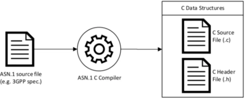
Abstract Syntax Notation One (ASN.1) is an interface description language for defining data structures that can be serialized and de-serialized in a standard, cross-platform way [29]. Because the language is both human-readable and machine readable, is extensively used in telecom industry, computer networking and to build up security protocols. Standardization bodies, like 3GPP, define data structures in ASN.1 modules, which are generally a section of a broader standard document or specification. These modules can be automatically turned into libraries for processing of their data structures by an ASN.1 compiler. Moreover, this descrip-tion language is closely associated with a set of encoding rules that specify how to present the ASN.1 data structures as a series of bytes during information exchange among communication systems. Among the others, the Packet Encoding Rules (PER, unaligned: UPER, canonical: CPER) is the reference Recommendation utilized by many open-source platforms including OpenAirInterface. In OAI software for instance, a specific directory is defined for contain-ing the necessary scripts and Makefiles to generate all the LTE configuration data structures based on the ASN.1 source code. In particular, an exctract_asn1_from_spec.pl script is used for extracting the “.asn” files from the text version of 3GPP specifications and turn it into “.c” and “.h” C-based files that can be directly used in the OpenAirInterface code. Figure 2.7
shows a general ASN.1 extraction process.
Figure 2.7: ASN.1 extraction process.
At runtime, the communication between two entities takes place through the usage of a UPER encoding script for transmission while a UPER-based decoder is used whenever data are received. This is exemplified in Figure 2.8.
2.5. Narrowband Internet of Things (NB-IoT)
2.5
Narrowband Internet of Things (NB-IoT)
On June 2016 the 3GPP completed the standardization of NB-IoT, a new LPWAN technology for the Internet of Things. NB-IoT is part of 3GPP Rel.13 specification (LTE Advance Pro) introduced as a new independent radio interface optimized for machine type traffic [6]. It is not fully backward compatible with existing 3GPP devices [7] though it ensures harmonious coexistence with current GSM, GPRS and LTE systems. To address key IoT requirements such as Machine Type Communication (MTC) the NB-IoT standard targets are derived:
– Massive connectivity
– Reduced UE complexity and costs – Improved power efficiency
– Coverage Extension – Deployment Flexibility
To fulfil these requisites, many advanced and even basic features of LTE Release 8 and 9 are not supported [10] while, at the same time, performance objectives led to a new system’s design for both Access and Core Network at various levels.
First, this section gives an overview on NB-IoT network and radio protocol architecture. Afterwards, details on Physical and Radio Resource Control layers are discussed focusing on those aspects that have been investigated during this Master thesis project.
2.5.1
Network Architecture
2.5.1.1 Core Network
NB-IoT it is not just an IoT platform and software upgrade but also the roll-out of new entities in the Core Network, called Cellular IoT (CIoT) Evolved Packet System (EPS), shown in Figure 2.9.
Figure 2.9: Core Network for the NB-IoT data transmission and reception. In red, the
Control Plane CIoT EPS optimisation is indicated while in blue the User Plane CIoT EPS optimisation [6].
The new NB-IoT Core Network offers two major optimizations [30]:
Control Plane CIoT EPS Optimization (Solution 2): is the basic and mandatory so-lution to support infrequent small data transmission (IP data, non-IP data and SMS) over Signalling Radio Bearers avoiding the establishment of Data Bearers to save bat-tery life. Non-IP data may be routed bi-directionally via the new network entity Service Capability Exposure Function (SCEF) or via SGW/PGW for IP data too.
User Plane CIoT EPS Optimization (solution 18): is the optional solution to support infrequent small data transmission (IP data and SMS) with the setup of up to 2 Data Radio Bearer for connection-oriented sessions.
A NB-IoT UE does not transfer data using both solution at the same time since both will be never configured by the network together. Instead, selection of which solution to be used is done between UE and network at Non-Access Stratum (NAS) level.
2.5.1.2 Access Network
From architecture view point, the NB-IoT Access Network has no difference to LTE as shown in Figure 2.10. The same S1 interface is used for connecting eNodeB to the MME and SGW and there is still an X2 interface between eNodeBs although no handover procedure is defined. Moreover, NB-IoT uses same frequency bands numbers as LTE but with a restricted set of 14 bands [31] most of which are in sub-GHz range, reflecting the need to leverage better coverage performance of UHF frequencies.
Figure 2.10: Network architecture towards the air-interface [6].
2.5.2
NB-IoT Radio Protocol Architecture
To build the NB-IoT protocol layers, 3GPP started with the LTE protocol specification, re-duced it to a minimum and optimized it as needed for NB-IoT. This way, the proven structures and procedures are re-used while overhead from unused LTE features is prevented. Conse-quently, the NB-IoT technology can be regarded as a new air interface also from the protocol stack view-point, while being built on a well established framework [6]. Figure 2.11 shows the E-UTRAN protocol stack architecture for NB-IoT highlighting Radio Bearers, logical, trans-port and physical channels, as well as the main protocol layers functionalities and data paths for both user- and control-plane.
As in legacy LTE, each PDCP entity is associated either to control or user data flows being assigned to Signalling or Data Radio Bearer respectively. However, the introduction of a new Radio Bearer, SRB1bis, grants to bypass PDCP before security activation or whenever CIoT Control Plane solution is adopted by the core network. Moreover, PDCP SDU maximum size is reduced from 8188 to 1600 octects and only short size 7 bits Sequence Number (SN)
is allowed instead of the 15 or 18 bits available. As for RLC layer, NB-IoT foresees to
work only on Transparent and Acknowledged Mode with the possibility of choosing whether or not configure Status Report functionalities for reception failure directly from RRC layer. Moreover, NB-IoT reduced set of resources is posing challenges on radio resource management
2.5. Narrowband Internet of Things (NB-IoT)
Figure 2.11: NB-IoT radio protocol stack architecture.
and assignment, in particular on MAC scheduler design which is considered by the scientific community one of the fundamental block of this new radio technology. Nevertheless, the most important modifications have been introduced in the PHY and RRC layer which will be discussed in the following subsections.
2.5.3
PHY
NB-IoT technology works on a 180 kHz bandwidth, i.e. one LTE PRB, applying a Type-B Half-Duplex Frequency Division Duplexing (FDD) mode with an additional subframe between every UL to DL switch [8]. The NB-IoT cell can be logically seen as a parallel cell to LTE having its own Narrowband Physical Cell Identity (NCellID), synchronization and physical signals. Therefore, deployment scenarios foresee three possible operating modes:
Stand Alone: the NB-IoT carrier is allocated irrespectively form the LTE band. Possible solution is the deployment over a GSM frequency carrier of 200 kHz bandwidth. In-Band: the NB-IoT carrier is allocated within the LTE cell utilizing same resource blocks.
However, the 100 kHz UE search raster implies that for in-band deployment a NB-IoT carrier can be placed only in certain PRBs [7]. Moreover, there is no support of this solution over LTE bands with 1.4 MHz bandwidth.
Guard Band: the NB-IoT carrier is allocated over the unused resource blocks within the LTE carrier’s guard bands.
The NB-IoT operating modes are shown in Figure 2.12:
Figure 2.12: Examples of NB-IoT stand-alone deployment and LTE in-band and guard-band deployments in the downlink [7].
Furthermore, to cope with different radio conditions, NB-IoT technology aims on 20 dB link budget higher than LTE Rel.12, reaching up to 164 dB of Maximum Coupling Loss (MCL) [7]. Coverage extension is achieved allowing large number of repetitions, up to 2048 in downlink and up to 128 for uplink. These are managed by MME that configures up to 3 Coverage Enhancement (CE) levels to set the number of times a message should be repeated depending upon UE location.
2.5.3.1 Downlink
In the Downlink, Orthogonal Frequency Division Multiplexing (OFDM) scheme is adopted using a 15 kHz subcarrier spacing with 7 OFDMA symbols bounded into 1 slot of 0.5 ms. Slots are summed up into subframes and radio frames in the same way as for LTE as reported by Figure 2.13 in which the NB-IoT downlink resource grid is for size of one single PRB. Also in this case, a Resource Element (RE) is defined as one subcarrier in one OFDMA symbol as indicated in Figure 2.13 by one square. However, the RE channel mapping varies depending if In-Band, Guard Band or Stand Alone operating mode is deployed. In addition, NB-IoT introduces the concept of Hyper-System Frame Number (HSFN) which counts legacy LTE System Frame periods incrementing by 1 each time the SFN wrap around (i.e. every 1024 frames). This new time basis results useful for energy saving mechanism such as Power Saving Mode (PSM) or extended Discontinuous Reception (eDRX) on which long interval of time are considered.
For the Downlink, NB-IoT defines three physical signals:
• Narrowband Reference Signal (NRS): transmitted every NB-IoT downlink subframe. • Narrowband Primary Synchronization Signal (NPSS): transmitted in subframe #5. • Narrowband Secondary Synchronization Signal (NSSS): transmitted in subframe #9 of
even radio frames. and three physical channels:
• Narrownband Physical Broadcast Channel (NPBCH): transmitted in subframe #0. • Narrowband Physical Downlink Control Channel (NPDCCH): transmitted in remaining
subframes.
• Narrowband Physical Downlink Shared Channel (NPDSCH): transmitted in remaining subframes previously scheduled through NPDCCH.
These, are primarily multiplexed in time generating the NB-IoT downlink subframe structure reported in Figure 2.14 for both odd and even frames.
2.5. Narrowband Internet of Things (NB-IoT)
Figure 2.13: LTE Downlink Resource Grid [8].
Figure 2.14: NB-IoT Downlink Subframe [9].
As can be noticed, there are less downlink channels than for LTE. For instance, Physical Multicast Channel (PMCH) is not included since no eMBMS service is defined for NB-IoT.
2.5.3.2 Uplink
In the UL, Single Carrier Frequency Division Multiple Access (SC-FDMA) with 3.75 kHz or 15 kHz subcarrier spacing is applied. For 15 kHz, same resource grid of Figure 2.13 applies while for 3.75 kHz the modified structure in Figure 2.15 for 2 ms slot is used. Again there are 7 OFDM symbols within a single slot.
For the Uplink, NB-IoT defines two physical channels:
• Narrowband Physical Uplink Shared Channel (NPUSCH) • Narrowband Physical Random Access Channel (NPRACH) and one reference signal:
Figure 2.15: NB-IoT resource grid for 3.75 kHz subcarrier spacing. There are 48 subcarriers for the 180 kHz bandwidth [6].
Except for RACH transmission, all data are transmitted over NPUSCH including also the Uplink Control Indication (UCI) since there is no equivalent to the LTE PUCCH for NB-IoT [6]. Over NPUSCH, the smallest unit to mapping a transport block is called Resource Unit (RU) whose definition depends on subcarrier spacing and NPUSCH Format used as described in [8] chapter 10.1.2.3. Moreover, the new NPRACH implements pseudo-random single-tone frequency hopping for preamble transmission as specified in [8] chapter 10.1.6.
For the sake of completeness, Table 2.1 summarizes the major changes introduced at physical layer by NB-IoT in comparison to legacy LTE Rel.9. Some of them have been discussed in this subsection, others are reported to give a wider look to this new radio technology.
LTE Rel.9 NB-IoT (LTE Rel.13) System Bandwidth 1.4 MHz, 3 MHz, 5 MHz, 10 MHz, 15 MHz, 20 MHz 180 kHz (200 kHz)
Duplexing Mode Full Duplex FDD/TDD Half-Duplex FDD Throughput DL: 150 Mbps, UL: 50 Mbps DL/UL (tilde) 200 Kbps Operating Mode LTE Licensed Spectrum In-Band, Guard Band, Stand Alone Maximum Coupling Loss (MCL) ∼ 145 dB ∼ 164 dB
Carrier Spacing DL/UL: 15 kHz DL: 15 kHz, UL: 15kHz or 3.75 kHz Transmission Mode TM1-TM9 TM1/TM2 (1 antenna or 2 antenna) Synchronization Signal PSS/SSS NPSS/NSSS
Detection of UL and DL channel DL: CRS, UL: DMRS DL: NRS, UL: DMRS Downlink Channel
PDSCH NPDSCH
QPSK, 16 QAM, 64 QAM QPSK
1/3 Turbo Coding 1/3 Tail biting convolutional coding 1 subframe for Transport Block 1 or more subframes for Transport Block Control Channel
PDCCH NPDCCH
Use 1 to 3 OFDM symbols of the first slot of the same PDSCH subframe Use an entire NB-IoT DL subframe DCI Format: 0, 1, 1A, 2, 2A, 3, 3A, ... DCI Format: N0 (UL), N1 (DL), N2 (DL)
Uplink Channel
PUSCH NPUSCH
15 kHz sub-carrier spacing 15 kHz or 3.75 kHz sub-carrier spacing 1/3 Turbo Coding 1/3 Turbo Coding
Use 1 subframe for transmission Resource allocation based on Resource Unit (RU) UL-SCH and UCI over same subframe UL-SCH without UCI
Low Power Consumption Technique DRX PSM, eDRX
2.5. Narrowband Internet of Things (NB-IoT)
2.5.4
RRC
Similarly to the physical layer, NB-IoT introduces drastic changes at RRC layer too, with the establishment of new messages and dedicated Information Element (IE). Being a non backward-compatible variant of E-UTRAN, some of the normal LTE functionalities and cor-responding procedures are not supported in NB-IoT while others equally apply. These, are partially summarized in Table 2.2 with reference to 3GPP Rel.13 specification available at [10]. However, with further releases, new RRC capabilities have been introduced for NB-IoT but not reported here since out of the scope of this Master thesis.
Not Supported Supported
Connected Mode Mobility (Handover and measurement reporting) System Information Inter-RAT cell reselection or inter-RAT mobility in connected mode Connection Control Relay Node (RN) DL Information Transfer Dual Connectivity (DC) UL Information Transfer Carrier Aggregation (CA) UE Capability Transfer MBMS (Multimedia Broadcast Multicast Service) General Error Handling Self-configuration and self-optimisation
Measurement configuration and reporting
Sidelink (including direct communication and direct discovery) Real time services (including emergency call)
Table 2.2: RRC features and procedures not supported or supported by NB-IoT [10].
Additionally, the usage of different CIoT solutions for data transfer (see subsubsection 2.5.1.1) introduced some exceptions on the RRC Connection Control procedures that can be applied depending on whether user- (UP) or control-plane (CP) optimization is adopted. This is shown in Table 2.3.
Connection Control Procedures CP UP
Paging X X
RRC connection establishment X X
RRC connection resume X
Initial Security Activation X
RRC connection reconfiguration X
RRC connection re-establishment X
RRC connection release X X
RRC conection release requested by upper layers X X
Radio resource configuration X X
Radio link failure related actions X X
UE actions upon leaving RRC_CONNECTED X X
Table 2.3: RRC Connection Control procedures for different CIoT EPS Optimization.
Since no handover to LTE or different Radio Access Technology (RAT) is supported, the NB-IoT RRC state transition model simplifies to the one shows in Figure 2.16.
As in LTE, there are only two states, RRC_IDLE and RRC_CONNECTED, without other associated UTRA or GSM states. RRC_CONNECTED to RRC_IDLE transition occurs whenever Radio Link Failure or cell selection/re-selection is required. In the latter case, the UE has first to release the connection, selects another “suitable” cell [32] and establishes a new communication.
Figure 2.16: Model of RRC states and their transitions.
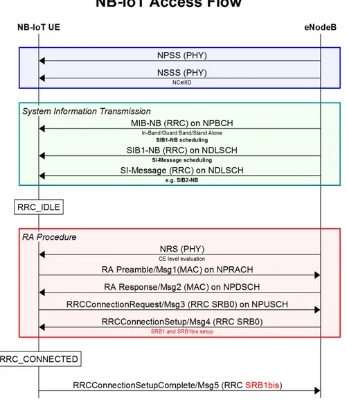
Physical Cell ID (NCellID), time slot and frame synchronization through NPSS and NSSS. Then, the UE reads associated System Information Blocks (SIBs) and starts the Random Access Procedure to establish an RRC Connection and register within the core network. The NB-IoT cell access flow with corresponding messages is reported in Figure 2.17. To be noticed that a NB-IoT (-NB) version for System Information as well for RRC messages is defined, while Random Access procedure has the same message flow as LTE although with different carried parameters.
Figure 2.17: NB-IoT cell access flow.
Overall, NB-IoT introduced further changes on UE Capabilities, Access Barring, Establish-ment Causes, Radio Link Failure and other procedures involving RRC layer at different levels. In the remaining part of this section, the new Radio Bearer and System Information design for NB-IoT are discussed, since of primary interest for this Master thesis and for the work
2.5. Narrowband Internet of Things (NB-IoT)
presented in the following chapters.
2.5.4.1 Radio Bearers
Similarly to LTE, NB-IoT radio bearers are classified as Data Radio Bearers (DRBs) and Signalling Radio Bearers (SRBs). In particular, the latter are partly re-used from legacy LTE systems by NB-IoT which defines three [10]:
• SRB0: is for carrying common RRC messages transmitted using CCCH logical channel. • SRB1: is for carrying dedicated RRC messages (which may include a piggybacked NAS
message) as well NAS messages, all using DCCH logical channel.
• SRB1bis: is for carrying dedicated RRC messages (which may include a piggybacked NAS message) as well NAS messages prior the activation of security, all using DCCH logical channel.
As can be noticed, there is no SRB2 defined but, in addition, a new Signalling Radio Bearer 1bis (SRB1bis) is introduced as previously highlighted in Figure 2.17. SRB1bis is implicitly established with SRB1 using the same configuration but no PDCP entity [10]. This because, it takes the role of SRB1 until security is activated and then is not used anymore [6]. SRB1bis distinguishes from SRB1 by only the Logical Channel Identity (LCID) that is equal to 3 instead of 1. Moreover, for NB-IoT UEs that only supports the mandatory Control Plane CIoT EPS optimization (see subsubsection 2.5.1.1) SRB1bis is always used since there is no security activation in this mode.
As for Data Radio Bearers, instead of the 8 allowed by LTE, NB-IoT has reduced the number. To keep the complexity low, a NB-IoT UE supports 0,1 or only up to 2 DRBs
simultane-ously, depending on its capability. These, are configured together with Signalling Radio
Bearers through RRCConnectionSetup-NB or RRCConnectionReconfiguration-NB messages. Furthermore, A NB-IoT UE that only supports the Control Plane CIoT EPS optimisation (see subsubsection 2.5.1.1) does not need to support any DRBs and associated procedures.
2.5.4.2 System Information
NB-IoT defines a reduced set of System Information Blocks, indicated with suffix “-NB”, with similar functionalities as LTE but modified Information Elements (IEs). These, are shown in Table 2.4 with reference to 3GPP Rel.13. Further SIBs have been introduced in NB-IoT Rel.14 and later versions available at [10] but not reported here since out of the scope of this Master thesis.
System Information Block Content
MasterInformationBlock-NB (MIB-NB) Essential information required to receive further System Information SystemInformationBlockType1-NB (SIB1-NB) Cell access and selection, information for other SIB scheduling SystemInformationBlockType2-NB (SIB2-NB) Radio resource configuration information
SystemInformationBlockType3-NB (SIB3-NB) Cell re-selection information for intra-frequency, inter-frequency
SystemInformationBlockType4-NB (SIB4-NB) Neighbouring cell related information relevant for intra-frequency cell re-selection SystemInformationBlockType5-NB (SIB5-NB) Neighbouring cell related information relevant for inter-frequency cell re-selection SystemInformationBlockType14-NB (SIB14-NB) Access Barring parameters
SystemInformationBlockType16-NB (SIB16-NB) Information related to GPS time and Coordinated Universal Time (UTC)
Table 2.4: NB-IoT System Information Blocks for 3GPP Rel.13.
NB-IoT UE exclusively use these SIBs and ignore those from LTE, even in the case of in-band operation. It is always mandatory for a UE to have a valid version of MIB-NB, SIB1-NB and SIB2-NB through SIB5-NB [10] while other SIBs are needed only if their functionalities
are required. Moreover, System information acquisition and change procedure is only applied in the RRC_IDLE state, therefore, NB-IoT UEs are not expected reading SIB information while being in the RRC_CONNECTED state [6]. Furthermore, to cause minimum UE battery consumption, the physical layer imposes a limit of 680 bits to the maximum size a SIB and SI message can take [33].
2.5.4.3 System Information Scheduling
In terms of sequence of decoding, NB-IoT takes a similar approach to LTE. It starts first with MIB-NB, then gets SIB1-NB and finally extracts SI-Messages containing SIB2-NB and other Information Blocks. However, the most outstanding difference between the two radio technologies is that for NB-IoT there is no Downlink Control Indication (DCI) associated to SI or SIBs. All necessary information to acquire System Informations are notified to UE over MIB-NB first and SIB1-NB later as highlighted in bold in previous Figure 2.17. This defines a “NPDCCH-less” approach in which scheduling parameters are fixed instead of being dynamically indicated on NPDCCH. Moreover, NB-IoT SI messages are transmitted discon-tinuously to take advantages of time diversity since spreading out transmission across time can improve performance at very low Signal-to-Noise Ratio (SNR) conditions [34]. In the fol-lowing, scheduling procedure for Narrowband Master Information Block, System Information Block 1 and System Information Messages is discussed since constitutes the starting point for the work presented in subsubsection 5.1.5.2.
MIB-NB Scheduling The Narrowband Master Information Block (MIB-NB) is the fun-damental message needed to acquire essential information from the cell on which the UE is camped. Therefore, its scheduling results in the most frequent transmissions and repetitions by the eNodeB. MIB-NB contains 34 bits and is transmitted over the NPBCH channel using a fixed schedule with a periodicity of 640 ms (64 radio frames) over which repetitions are made. The first transmission of the MIB-NB is scheduled in subframe #0 of radio frames for which SF N mod64 = 0 and repetitions are made in subframe #0 of all the next consecutive radio frames. Moreover, due to baseband processing, the MIB-NB transmission is arranged in 8 independent decodable blocks of 80 ms duration each. The first block is transmitted in the first subframe of the starting radio frame and repeated in subframe #0 of the next 7 consec-utive radio frames, respectively. In the subframe #0 of the following radio frames the same procedure is applied for MIB-NB Block #2 (BL2) and all the others blocks. This process is continued until the whole Narrowband Master Information Block is transmitted. Figure 2.18 shows the MIB-NB scheduling highlighting frames, subframes numbers and decodable blocks delivery.
SIB1-NB Scheduling The Narrowband System Information Block Type1 (SIB1-NB) is transmitted over the NPDSCH channel using a fixed schedule with periodicity of 2560 ms (256 radio frames) over which 4, 8 or 16 equally spaced repetitions are made. SIB1-NB transmission occurs in subframe #4 of every other frame in 16 continuous frames [10]. Four possible Transport Block Sizes (TBSs) of 208, 328, 440 and 680 bits are defined and SIB1-NB content may only be changed on each modification period, which has a length of 4096
radio frames, i.e. 40.96 seconds. The SIB1-NB starting radio frame and the number of
repetitions are derived from the eNodeB Narrowband Physical Cell Identity (NCellID) and from the schedulingInfoSIB1 parameter delivered in the Narrowband Master Information Block. Figure 2.19 reports the evaluation procedure for SIB1-NB repetitions and starting radio frame through Table 16.4.1.3-3 and Table 16.4.1.3-4 as specified in [33]. Moreover, Figure 2.20 shows the resulting SIB1-NB scheduled transmission in subframe #4 with starting radio frame #16 and repetition number 4.
2.5. Narrowband Internet of Things (NB-IoT)
Figure 2.18: MIB-NB scheduling.
Figure 2.19: Evaluation procedure for SIB1-NB repetitions and starting radio frame.
Figure 2.20: SIB1-NB scheduling example. Starting radio frame #16 and repetition number 4.
Since repetitions are equally spaced and in each of them SIB1-NB is delivered in every other frame within 16 continuous ones, transmissions may occur in odd or even frames depending
if the starting radio frame is an odd or even number, respectively. Moreover, given the
repetitions characteristics, the following formula can be used to calculate the repetition offset in radio frames (rf):
Of f set = 256rf − (16 · n_repetitions)
with n_repetitions given by Table 16.4.1.3-3 shown in Figure 2.19.
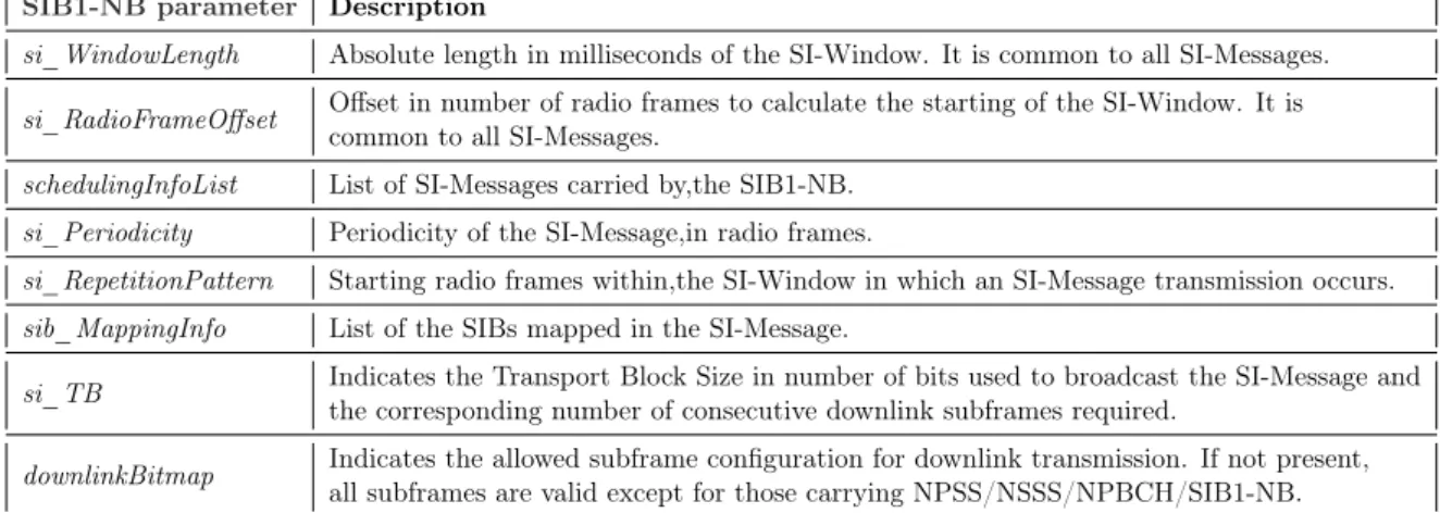
SI-Message Scheduling Narrowband System Information Blocks (SIBs) other than SIB1-NB and with same scheduling requirements are mapped and carried in System Information Messages (SI-Messages) with the mapping procedure that is flexibly configurable by the schedulingInfoList parameter carried by SIB1-NB. As for LTE system, also in NB-IoT the SystemInformationBlockType2-NB is always mapped in the SI-Message that corresponds to the first entry of the scheduling list of SIB1-NB. As previously mentioned, the SI-Messages scheduling is “NPDCCH less”: all the necessary scheduling information for the message acqui-sition by the UE like timing, Transport Block Size (TBS) and repetition patterns are directly indicated by SIB1-NB parameters instead of being dynamically specified in a DCI. SI-Messages are transmitted within periodically occurring time domain windows, referred as SI-Windows, using scheduling information provided in SIB1-NB. Each SI-Message is associated with its own SI-Window, and SI-Windows of different SI-Messages do not overlap [10] such that the UE receives only one single information message within one SI-Window. The window length and its possible starting offset are common to all SI-Messages and are configurable through the SIB1-NB’s si_windowLength and si_RadioFrameOffset parameters respectively. More-over, within the SI-Window the corresponding SI-Message is transmitted over a number of consecutive downlink subframes depending on the TBS. For instance, a TBS of 56 or 120 bits requires only 2 subframes while other TBSs are transmitted over 8 subframes.
Table 2.5 summarizes the most relevant parameters provided by SIB1-NB for SI-Messages scheduling together with a brief description of their functionalities.
SIB1-NB parameter Description
si_WindowLength Absolute length in milliseconds of the SI-Window. It is common to all SI-Messages. si_RadioFrameOffset Offset in number of radio frames to calculate the starting of the SI-Window. It is
common to all SI-Messages.
schedulingInfoList List of SI-Messages carried by,the SIB1-NB. si_Periodicity Periodicity of the SI-Message,in radio frames.
si_RepetitionPattern Starting radio frames within,the SI-Window in which an SI-Message transmission occurs. sib_MappingInfo List of the SIBs mapped in the SI-Message.
si_TB Indicates the Transport Block Size in number of bits used to broadcast the SI-Message and the corresponding number of consecutive downlink subframes required.
downlinkBitmap Indicates the allowed subframe configuration for downlink transmission. If not present, all subframes are valid except for those carrying NPSS/NSSS/NPBCH/SIB1-NB.
Table 2.5: Relevant SIB1-NB parameters for SI-Message scheduling.
As reported in [10] and based on parameters of Table 2.5, every SI-Window starts in subframe #0 in the radio frame that satisfies the following formula:
(HSF N · 1024 + SF N )modT = F LOOR(x
10) + Of f set (2.2)
where T is the si_Periodicity, Of f set corresponds to si_RadioFrameOffset and x is an integer value determined from the formula:
x = (n − 1) · w (2.3)
with w the si_WindowLength and n a number corresponding to the order of entry of the concerned SI-Message in the schedulingInfoList of SIB1-NB.
After determining the SI-window start, a NB-IoT UE accumulates SI-Message transmissions on Downlink Shared Channel (DLSCH) until the end of the window, starting from the radio
2.5. Narrowband Internet of Things (NB-IoT)
frames as provided by si_RepetitionPattern and in subframes as provided by downlinkBitmap, if defined, until a successful decoding of the message. In the following, a simple transmission example of two SI-Messages (SI_1 and SI_2) is shown in Figure 2.21 with the corresponding parameters setup reported in Table 2.6.
SI_1 parameter Value
si_WindowLength 160 ms
si_RadioFrameOffset 0
si_Periodicity 64 RF
si_RepetitionPattern Every2ndRF
sib_MappingInfo sibType3_NB, sibType4_NB, sibType5_NB
SI_2 parameter Value
si_WindowLength 160 ms
si_RadioFrameOffset 0
si_Periodicity 128 RF
si_RepetitionPattern Every8thRF
sib_MappingInfo sibType14_NB, sibType16_NB
Table 2.6: SIB1-NB parameters setup for SI_1 and SI_2 message scheduling of Figure 2.21.
Figure 2.21: SI-Message scheduling example.
In NB-IoT, various possible configurations of System Information delivery poses challenges on efficient combination of SI-Message transmission together with SIB1-NB and MIB-NB. This is also dependent on messages’ TBS which affects the number of downlink subframes needed. For instance, block sizes greater than 120 bits require 8 subframes for SI-Message delivery and if the SI transmission frame coincides with the SystemInformationBlock1-NB one, there will be one subframe less (subframe #4). As a consequence, an UE might be unable to completely receive a SI-Message in one single frame but should continue to receive remaining parts in other radio frames following the si_RepetitionPattern. This and other aspects on System Information scheduling will be resumed in subsubsection 5.1.5.2.
![Figure 2.1: The three main 5G use cases and examples of associated applications [1].](https://thumb-eu.123doks.com/thumbv2/123dokorg/7425257.99210/20.892.221.658.99.542/figure-main-g-use-cases-examples-associated-applications.webp)
![Figure 2.3: Block Diagram of an ideal Software Defined Radio system [3].](https://thumb-eu.123doks.com/thumbv2/123dokorg/7425257.99210/22.892.155.718.513.718/figure-block-diagram-ideal-software-defined-radio.webp)
![Figure 2.13: LTE Downlink Resource Grid [8].](https://thumb-eu.123doks.com/thumbv2/123dokorg/7425257.99210/31.892.290.632.99.562/figure-lte-downlink-resource-grid.webp)
![Figure 2.15: NB-IoT resource grid for 3.75 kHz subcarrier spacing. There are 48 subcarriers for the 180 kHz bandwidth [6].](https://thumb-eu.123doks.com/thumbv2/123dokorg/7425257.99210/32.892.207.663.99.305/figure-iot-resource-grid-subcarrier-spacing-subcarriers-bandwidth.webp)
![Table 2.2: RRC features and procedures not supported or supported by NB-IoT [10]. Additionally, the usage of different CIoT solutions for data transfer (see subsubsection 2.5.1.1) introduced some exceptions on the RRC Connection Control procedures that can](https://thumb-eu.123doks.com/thumbv2/123dokorg/7425257.99210/33.892.232.685.668.924/procedures-supported-additionally-subsubsection-introduced-exceptions-connection-procedures.webp)