SCHOOL OF ENGINEERING AND ARCHITECTURE
DEPARTMENT OF ELECTRICAL, ELECTRONIC AND INFORMATION ENGINEERING “GUGLIELMO MARCONI”
MASTER DEGREE IN
ELECTRICAL ENERGY ENGINEERING
MASTER THESIS in
Applied Measurements for Power Systems
DESIGN AND CHARACTERIZATION OF A SYSTEM FOR LOSS FACTOR MEASUREMENT IN MV UNDERGROUND CABLE JOINTS
UNDER TEMPERATURE VARIATION CONDITIONS
AUTHOR SUPERVISOR:
Filippo Lama Prof. Lorenzo Peretto
CO-SUPERVISORS: PhD. Abbas Ghaderi Prof. Roberto Tinarelli
Abstract...1
Sommario...3
1 Introduction... 5
1.1 Background... 5
1.2 Problem statement...6
1.3 Objective and approach...6
1.4 Thesis organization... 7
2 Theory...9
2.1 MV Cable Joints... 9
2.1.1 Field grading systems...10
2.1.1.1 Geometrical stress control... 11
2.1.1.2 Refractive stress control ... 12
2.1.2 Construction procedure... 14
2.1.2.1 Installation site...14
2.1.2.2 Cable preparation...15
2.1.2.3 Connectors...16
2.1.2.4 Main insulation application: heat shrink and cold shrink joints...18
2.1.2.5 Metallic shield and outer protective sheath... 21
2.1.3 Cable joint overall view ... 22
2.2 Analysis of cable joint failure rate... 24
2.2.1 Influence of ambient temperature on cable joint failure rate...28
2.3 Theory of interfacial discharges ...31
2.3.1 Mechanism of interfacial breakdown...32
2.3.2 Parameters affecting the breakdown strength at dielectric interfaces...35
2.3.2.1 Effect of insulating liquid or grease...35
2.3.2.2 Effect of surface roughness ... 36
2.3.2.3 Effect of contact pressure... 37
3.1 Test objects...45
3.1.1 REPL joints... 45
3.1.2 In-field made joints... 46
3.2 Tan delta measurement circuit... 48
3.2.1 Working principles... 48
3.2.2 Design of circuit parameters... 53
3.2.2.1 Design of the input voltage...54
3.2.2.2 Design of resistance values... 57
3.2.3 Resistor characterization... 61
3.2.4 Thermostatic chamber and temperature cycles... 68
3.3 Measurement LabVIEW program...70
3.3.1 Data acquisition...71
3.3.2 Data processing... 73
3.3.2.1 Joint voltage and current calculation...73
3.3.2.2 Joint capacitance, impedance and tan delta calculation...75
3.3.2.3 Saving of data... 76
3.3.3 Front panel... 78
3.4 Measurement procedure...79
3.4.1 Safety precautions... 81
4 Results... 83
4.1 Statistical analysis of measurement data...83
4.1.1 Systematic error analysis...84
4.1.2 Random error analysis...85
4.2 Tan delta measurement results... 90
4.2.1 MATLAB functions for measurement result calculation and plot...90
4.2.2 Measurement results...92
4.2.2.1 Tg 100 REPL Cable Joint sample...93
4.2.2.2 Tg 150 REPL Cable Joint sample...95
4.2.2.3 In-field Cable Joint sample n°1... 96
6 Conclusion and future works... 111 7 Acknowledgments...115 8 References...117
Abstract
Cable joints are considered to be the weakest components of the MV cable network, being the ones with the highest failure rate. Furthermore, from statistical analysis of different cable network failure data, a noticeably increase in cable joint breakdowns has been showed during summer months. The request for Distribution System Operators to avoid line outages as much as possible indicates a significant need for non-invasive diagnostic technologies able to monitor the health condition of MV cable junctions. Moreover, a better knowledge is required on the main causes of the detected increase in cable joint failure rate, in which temperature seems to play an important role. The present master thesis consists in the design and complete characterization of a simple and cheap laboratory setup for loss factor measurements on cable joints. Using the developed circuit, tan delta measurements are performed on four thermally cycled cable joint samples and the trend in relation to temperature variations has been investigated and widely discussed. In particular, it has been found that the loss factor of cable joint samples decreases considerably when temperature rises and vice-versa. From result analysis, some hypotheses have been made trying to explain this particular behavior of the loss factor versus temperature. In particular, temperature variations seem to cause expansions and contractions of the different dielectric layers present in cable joint, giving rise to pressure fluctuations at the interface between them. Consequently, variations in the breakdown strength of the joint insulation system and in the amount of conduction losses are expected to happen. These conclusions must be demonstrated by future studies and tests on cable junctions. It is worth saying that a conference proceeding has been published from the present work, and, currently, a journal paper is submitted, waiting to be approved.
Sommario
I giunti sono considerati i componenti della rete di media tensione in cavo aventi il più alto tasso di guasto. Per le utilities di distribuzione è di primaria importanza ridurre il più possibile il numero di interruzioni delle linee in cavo. Sono dunque necessari maggiori studi diagnostici riguardanti il monitoraggio delle condizioni operative dei giunti di media tensione. Oltre a ciò, è richiesta anche una maggiore analisi delle cause che portano, nei mesi estivi, ad un considerevole aumento di guasti nei giunti stessi. In particolare, sembra che le variazioni di temperatura abbiano un ruolo di primaria importanza in tale fenomeno. La presente tesi magistrale consiste nel design, nella caratterizzazione e nella taratura di un semplice ed economico setup di laboratorio per la misura del fattore di perdita nei sistemi di isolamento di giunti di media tensione. Utilizzando il circuito sviluppato, il fattore di dissipazione viene misurato in quattro giunti sottoposti a cicli termici. Viene dunque analizzato l’andamento del fattore di dissipazione in relazione alle variazioni di temperatura: ad un aumento di questa, il valore del fattore di perdita tende a diminuire e viceversa. Dall’analisi dei risultati, sono state effettuate ipotesi al fine di determinare le cause di tale andamento. In particolare, sembra che le variazioni di temperatura provochino espansioni e contrazioni dei diversi strati di isolante presenti nei giunti, causando dunque variazioni di pressione nell’interfaccia fra gli strati stessi. Da tali oscillazioni di pressione si ritiene che ne conseguano modificazioni nella rigidità dielettrica del sistema di isolamento della giunzione e nella corrente di conduzione che lo attraversa. Le precedenti ipotesi dovranno essere dimostrate e saranno oggetto di studio per futuri test. Dal presente lavoro, è seguita la pubblicazione di un contributo in atti di convegno e, attualmente, un articolo di ricerca è in attesa di essere pubblicato.
1 Introduction
1.1 Background
Underground cable joints are considered to be one of the MV cable network apparatuses with the highest failure rate [14; 15; 17]. In fact, cable joints are hand-made systems installed on field usually under non controlled environmental conditions. Hence, the entrance of contaminants in joint insulation during the installation and the relatively high possibility to make mistakes in the mounting are just a few of the factors that could lead to premature joint faults. The high criticality of these cable accessories can be also understood by highlighting that the sudden failure of only one cable joint leads to the outage of the entire cable line to which it is connected. A cable line outage due to a cable joint breakdown leads always to costly and time consuming maintenance actions since the whole component has to be replaced with hand working by specialized workmen. That fact causes also discomforts on the final users, experiencing long electric power interruptions. The request to avoid as much as possible such line failures indicates a significant need of non-invasive diagnostic methods and technologies to assess the condition not only of the whole cable system but also, particularly, of cable joint accessories. In fact, nowadays, several diagnostic techniques are actually used for the analysis of the whole cable line condition, considered as a system of cable segments, joints and terminations. However, a lack of investigations about simple and cheap techniques focusing directly on cable joints has been detected. Condition assessment of these apparatuses trough the monitoring of health parameters is of primary importance in order to apply predictive maintenance on them and consequently reduce the high number of failures caused by their breakdown. In particular, this work focuses on the application of the loss factor diagnostic tool on cable joints considering its advantage to provide a good estimation of the whole insulation health condition of the tested apparatus using a relatively simple and cheap laboratory setup.
1.2 Problem statement
The statistical analysis of different MV cable networks failure data show that cable joint failure rate increases noticeably during the summer months of the year [24; 25; 26]. From the same studies, it has been demonstrated that these peaks in cable joint breakdowns seem to be not correlated with their working conditions due to their low load conditions during all the monitoring years. Hence, it has been argued that environmental temperature could play an important role on the failure rate of cable joints. A possible explanation could be found in the continuous day-night temperature variation coupled with the mean high temperature of the summer period that may cause instabilities inside the joint structure. However, due to a lack of literature about this phenomenon, many investigation about the effect of temperature on the health state of complex insulation systems as cable joints have to be further performed. The effect of a better knowledge of this phenomenon is expected to lead to a better understanding on how it is possible to monitor cable joint health state on-site, considering always the final purpose to decrease of cable line outages events.
1.3 Objective and approach
The present master thesis has an approach mainly experimental and deals with underground medium voltage straight cable joints with different design and constructed in laboratory or on site. In view of the problems introduced in the latter, this work has the objective to design and completely characterize a simple and cheap laboratory setup to measure the loss factor of cable joint with a sinusoidal applied voltage having magnitude of 1kVrms and 50 Hz of frequency. Then, once the system has been designed
and constructed, loss factor measurements have been performed on cable joint samples subjected to hot-cold daily thermal cycles. The purpose is to investigate and discuss the response of the loss factor during variations of joint temperature. In particular, the target is to correlate loss factor variation to joint thermal condition in order to infer the effect of environmental temperature variation on the health condition of the joint. This work
has intended to be only the starting point for a deeper investigation on why so many cable joint fail during summer period. Hence, during the discussion of the results found, some suppositions, supported by literature data, have been made: these must be demonstrated by future works on this subject. It must be always remembered that the general aim is to find a method to perform in a reliable and cheap way diagnostic measurements on the most critical component of the cable network. In this way, it is expected to reduce of the high number of cable outages since preventive maintenance on cable joints could be effectively performed.
1.4 Thesis organization
The first chapter of this thesis is intended to be a brief introduction of the subject treated, highlighting also the aim and the objectives of the whole work. Chapter 2 is a theoretical overview about the literature present in the field of cable joints and loss factor measurements, explaining everything could be useful to the understanding of the measurement setup design and to the discussion of the loss factor results. In the third chapter is explained in detail the design and the characterization of the loss factor measurement circuit and LabVIEW program. Chapter 4 presents firstly how measurement data have been statistically analyzed, focusing on the measurement errors, and then loss factor results of cable joint samples are presented, focusing on the linking with the temperature condition of the joint themselves. In chapter 5, measurement results are widely discussed, making also some supposition, based on literature analysis, on the causes that lead to the found loss factor trend versus temperature. The conclusions and the future and works, required to demonstrate the suppositions made in the latter stage, are the objects of chapter 6. As last, chapter 7 and 8 contain respectively the acknowledgments for this master thesis and all the references, useful to support the theoretical part and the hypotheses made.
2 Theory
2.1 MV Cable Joints
Distribution power cables for medium voltage underground lines are usually manufactured with standard lengths of some hundreds of meters and they are delivered to the customers wound on drums. A typical drum containing, for example, 500 meters of XLPE insulated three core cable with conductor sections of 240 mm2 can weight up
to 7500 kg [1]. Then, because of handling issues for the cable factories, it is clear that there are manufacturing limits in terms of maximum length of the cable segments. Furthermore, very heavy drums with very long wounded cable segments would cause issues not only during the manufacturing processes but also during transportation and installation at site. Therefore, from what just said, in order to create long distance cable lines the only way is to connect together many cable segments using accessories called cable joints. Cable joints are then an integral part of a power cable distribution system and they must perform the same basic functions as the cable lines on which they are installed. In other words, they must behave totally as a perfect continuation of the cable line. Furthermore, in addition to providing conductor connections for the full current rating of the cable and an adequate insulation, cable joints must also ensure an electrical stress control at the cable screen ends and they must also protect the cable connection against water, dust or pollution ingress [2].
It must be underlined that, in the present study, only straight single core joints are analyzed, namely joints connecting two pieces of single core cables both insulated with polymeric materials, being the most common ones. Thus, different cable joint designs as three core cable joints, T or Y branch joints or transition joints for the connection of cables having different insulation materials (for example polymeric and paper insulated cables) are not treated in the present thesis. Now, the cable joint structure highly depends not only on the cable segments connected but also on the line voltage and operating environment: in this study medium voltage cable joints with voltage class of
36 kV are considered. In this case, the cable joint structure is similar to the one of the cables that it is connecting and, besides of connector and electric stress control, it includes joint insulation, joint insulation semiconductor, joint shield and outer sheath, as it will seen in the following [3]. However, also by only considering medium voltage straight joints, it is not possible to define a common general joint structure. In fact, the joint structure may vary depending on manufacturing choices about the field grading type and about the type of installation technology of the insulating materials. Thus, the subsequent treatment is organized in order to explain step by step the best practice for the installation of a medium voltage cable joint, focusing on the different possible solutions that could be used when two pieces of cables have to be connected together. However, to make lighter this part, it is better to explain firstly the most common methods used to perform electric field stress control and grading.
2.1.1 Field grading systems
Regarding medium voltage cable joints, electrical stress field control is required both at the outer semiconductor screen termination of the cable segment and at the cable connector position. In fact, as it will be explained in the 2.1.2 subsection, the cable joint installation requires the removal of both the cable shield and the outer semiconductive layer, external to the main cable insulation. Because of this, the electric field generated by the conductor is not confined anymore inside the insulation and critical electric field strengths occur at the cut edge of the outer cable seminconductive layer due to the densification of equipotential lines. Consequently, partial discharges or surface corona may occur in that region, reducing the lifetime of the entire system and enhancing the risk of breakdown [4]. In other words, the termination of the dielectric semiconductive screen produces an increase in the potential gradient between the dielectric and the surrounding space [2], as it can be seen in figure 2.1.
Considering the cable joint purpose, namely to electrically connect two cable segments, the removal of the cable shield and of the outer seminconductive layer is unavoidable since the inner conductor has to be made available for the connection.
Consequently, solutions to reduce the intensity of the electric field stress at the semiconductive screen end must be found. In particular, the two most common types of stress control used in cable joints to achieve a more distributed electric field are the geometrical stress control and the refractive stress control [3]. Other stress control technologies however exist, as impedance stress control or non linear stress control, but they are not analyzed in the present study.
2.1.1.1 Geometrical stress control
The main idea about geometrical stress control is to spread the equipotential lines more evenly by using a conductive cone shaped electrode (called also deflector) placed on the top of the cable, at the cut edge of the semiconductive screen. The equipotential lines follow the curved shape of the stress cone, especially designed for this purpose, resulting in a more uniform distribution of them, eliminating the high stress area highlighted in figure 2.1 with dashed lines. Thus, when the outer semiconductive layer is removed from a cable, the screen cut area is covered with a predesigned conductive cone, as rendered in figure 2.2, leading to a reduction of the potential gradient at the cable dielectric surface to a level in which discharges will not occur [2; 4].
The geometrical stress control is used in several MV and HV cable accessories and, in the case of cable joints, the conic electrode is nowadays directly extruded on the internal part of the main insulating body. In this way, the shape of the deflectors can be very carefully designed in order to spread the electric field present in the critical point
Fig 2.1: Ungraded electric field equipotential lines at
as much as possible. Sometimes, to achieve the latter objective, are used complex simulations and mathematical models, as it can be seen in studies [38; 39].
As it will be seen, this grading technology is used in general only in premolded cold shrink joints. In fact, variations of the designed cone shapes due to bad applications must be minimized: the installation and operative condition of stress cones are very important since stress control does not work properly if the ideal curve of the deflectors is deformed [6]. In other words, stress cones are used only in cold shrink cable joints since, during the installation of hot shrinkable insulating tubes, a not even application of the heat by the jointer might cause deformation of deflectors.
2.1.1.2 Refractive stress control
The main idea about refractive stress control is to use a layer of nonconductive material with high permittivity wrapped around the area where the electrical stress have to be lowered. As well explained in [4], this stress control method is based on the fact that the permittivity of the refractive material (εr2) is always much higher than the one of
the cable insulation (εr1) and of the surrounding environment (εr3). Thus it holds :
ϵr2> ϵr1≥ ϵr3 (1)
By figure 2.4 it can be seen that there is a change in the electrical field distribution where the insulation and refractive material are in touch. The magnitude of this
Fig. 2.2: Field distribution in a
cable end with geometric stress control [4].
refraction is determined by the incident angle of the flux lines, passing from one dielectric to another, and by the ratio of the dielectric constant of these materials. Thus, as expressed by equation (2), the higher is the dielectric constant ratio, the farther the electric field will be refracted towards the cable end [5].
tan(α2)
tan(α1)
= ϵr2
ϵr1 (2)
Hence, thanks to the latter equation, wrapping the cable end with material characterized by a very high permittivity, the equipotential lines are spread further apart determining an electric field coming from the cable insulation more gradually spread. The major limitation of this technique is the enhancement dielectric losses in the refractive material and, consequently, cable accessories in which this technique is applied must be designed with adequate heat transfer in order to avoid local overheating [4]. Furthermore, during the design of these kind of stress control system, it must be considered the fact that charge carriers may accumulate at boundaries between materials and affect the local field distribution [4]. Despite this, the use of high dielectric constant grading systems offers the advantage that, in order to achieve a more distributed electric field over the cable termination surface, only a simple extruded tube is used instead of a complex rubber molded stress cone: the device can be then more compact, while the same effect is reached [5]. Therefore, the use of these materials is extremely common for stress control purposes in polymeric cable accessories characterized by both hot shrink or cold shrink technologies. Furthermore, these materials can be provided in the joint kits as
Fig. 2.3: Electric flux refraction at dielectric
interface [5].
ϵr2
separated tubes to be shrunk before the installation of the main joint insulation or, even better, they can be directly extruded on the internal part of the joint main insulation tube leading to a reduction of bad installation risks.
2.1.2 Construction procedure
After the discussion about the needs of having a stress control on cable ends when the outer cable shield and semiconductor layer are peeled off, in the following the detailed joint construction procedure is going to be explained step by step. In this way, it is easy to present the main different types of medium voltage cable joint components that are used in practical applications.
2.1.2.1 Installation site
The first main aspect about joints that must be underlined is that, differently than power cables, which are extruded in factories in a controlled clean environment, the cable junctions are completely assembled and installed on field, where two cable lines have been already settled. Indeed, cable joint components are generally produced by manufacturers and sold to distribution utilities in kits that have to be mounted by expert workers at the installation site. Now, even if the environment in which cable segments
Fig. 2.4: Field distribution of a
cable end with refractive stress control material [4].
and joints are constructed is so different, it is required that they must have the same long term reliability. It follows that the joint installation is a crucial stage for the health of the entire cable line: the risk of contaminations or human errors during the joint mounting is very high. Thus, besides the obvious need of experienced jointers, also the characteristic of the installation site are very important. Best practice recommendations for a well planned joint site are [7]:
• a safe working environment;
• as dry as possible with no standing water in the working area; • sheltered from rain and wind;
• free from contaminations as dust. 2.1.2.2 Cable preparation
The preparation of cable ends that have to be connected is the first stage of joint installation and it is required for all types of joints. It must be remembered that, in the present work, only procedures referred to polymeric cables are considered. The cable preparation is performed considering the purpose to provide a proper electrical and mechanical integrity when the joint connection will be installed. In particular, the preparation procedure basically consist in the accurate peeling of all the cable insulating and semiconductive layers, one by one, using special tools. The metallic shield is them stripped back or the cut: the different procedure depends basically on the type of conductive screen present in the cable segment, namely a shield with copper wires or with aluminum foil [44]. Starting from the end of a cable segment, the objective of the jointer is to organize it as in figure 2.5, obtaining as final result all the different cable layers separated with enough distance to make connections properly.
It has to be highlighted that, during cable preparation, the worker must use specific removal tools depending on the cable insulation material and manufacturer in order to not perform a bad cable peeling. In particular, much care must be taken in not making cuts on the insulation surface or making an irregular conductive screen edge. These errors must be absolutely avoided since they can determine, for example, the creation of
air voids in the interface between the cable insulation and the main joint insulation. These voids are the perfect environment for partial discharges that could possibly lead to early-life failures, as it will be more clear later. Hence, cable joint installers must be aware about these possibilities and pay great attention on the cable preparation stage.
In the end, before installing the components of the joint kit, the prepared cables should be cleaned to remove any dirt and some insulating oil or grease should be spread over the cable insulation, using proper gloves [7; 44]. The reason of these actions will be more clear after the explanations about surface discharges, treated in section 2.3.
2.1.2.3 Connectors
Once the ends of both cable segments have been peeled off, the two bared conductors have to be tightly connected together, ensuring a good electrical connection. While the original method of making the connection between the two cable conductors was by soldering them, now this practice has been fully replaced by the use of metallic connectors which provide a reliable contact between the cables without the request of very skilled workers, as the soldering does [7]. In particular, the correct length of insulation have to be removed during the cable preparation to allow the full insertion of the bared wires into a metallic connector body. There are mainly two different connector types: compression connectors and mechanical (or bolted) connectors.
The compression connectors are constituted by a smooth aluminum or copper tube inside which the two conductor ends of the cable are inserted. Then, an hydraulic or
Fig 2.5: Single-core MV cable with strippable insulation screen and copper wire earth screen before
hand-operated press equipped with specially designed dies (indent, hexagonal or circumferential) is utilized to deform the metallic tube and produce a low resistance electrical contact with good mechanical grip between the two conductor ends [2].
The mechanical or bolted connectors consist in metallic cylinders provided by screws which are tightened in order to make a strict contact with the internally placed conductors ends. In MV applications, most of those have shear-head screws where the head part of the screw breaks away when the correct tightening torque is reached [7]. After the screws break, the connector surface must be smoothened to obtain a cylindrical shape and so prevent electric field peaks: projecting points are removed with abrasive tools and semiconducting tape or mastic is usually added inside the holes left by the breaking of the screws [3].
Like compression connectors, also the mechanical ones provide a good connection also if they are installed by operators with lower skills comparing to the ones required for soldering. Furthermore, mechanical connectors have the advantage of not requiring
Fig. 2.6: Hexagonal compression die and copper
compression connector [7].
particular installation tools, as the compression ones. In contrast, they are more expensive due to the major manufacturing processes needed.
2.1.2.4 Main insulation application: heat shrink and cold shrink joints
After the installation of the connector, the joint main insulation has to be mounted. Its purpose is to protect the active parts from ground, as in a conventional cable line. Furthermore, since the removal of the shield over the cable insulation layer changed the radial symmetric distribution of the electric field and consequently high stress areas are created at semiconductor shield end, also the field grading system has to be installed. Its purpose, as previously explained, is to better spread the equipotential lines and eliminate the mentioned high stress regions. Now, cable joints can be categorized in different groups depending on the main insulation installation technology. In all the cases, the aim is to insulate the inner connector from ground using a tube made of dielectric elastomeric material that has to be shrunk as tight as possible around the connector itself. It is exactly this shrinking technology that differentiate the type of cable joint. In particular, the heat shrink joint type indicates that the insulating material tube and the cable jacket are tightened by heating; the cold shrink joint type indicates that the insulating tubes are stretched onto a plastic spiral and placed on the cable as they contract when the spiral is removed [8]. In the following, these two main insulating technologies are discussed more in detail considering also the most common field grading system used for every joint type.
The heat shrinkable property is created firstly by extruding or molding the polymeric material into the required cylindrical shape and then by crosslinking them. The components are subsequently warmed, expanded and cooled in this expanded state: when heat will be applied to the material, the memory given by the crosslinking causes the fact that the material tends to return to the shape in which it was crosslinked [2]. On medium voltage joint kits that are based on this technology some different heat-shrinkable tubes are usually present. They have different purposes, namely refractive
stress control, insulation, screening and environmental protection jacket. These tubes have to be concentrically heat shrunk one after the other. However, more modern joint kits include on one single heat-shrinkable body more tubes extruded together, as the stress control tube and main insulation, in order to ensure an easier and faster installation, making less probable human errors in shrinking the materials. The installation process of heat shrinkable tubes consists in the positioning and in the heating of them with propane or butane gas torches (figure 2.8) until the tube uniformly shrinks around the cable connector or around the underlaying tube [7]. It must be underlined that, before the tube shrinking, usually some void filler adhesive tapes are wrapped around the cable seminconductive screen ends and sometimes around the cable connector. Independently by the type of semiconductive screen or metallic shield removal method, this practice reduces the probability of air void formations in these high stress areas, after the installation of the tubes; it is an important practice, since, these voids are the region in which partial discharges, driven by the high electric field, are usually located, causing eventually the breakdown of the cable joint [9].
The heat shrink technology is widely used for junction applications due to its capability of covering wide ranges of cable types and sizes. However, its clear disadvantage is the need of heating means on site (usually a gas flame) and, mostly, the requirement of expert and skilled jointers able to shrink the various tubes in an uniform way, without creating dangerous air voids on the internal part of the insulating tube [10]. Cold shrink technology offers an application range in terms of cable sizes similar to that
of heat shrink one but without the requirement of heat application. Cold shrink technology is based on elastomeric flexible materials as silicon rubber (SiR) or EPDM. The insulating tube is pre-stretched by the manufacturer onto a plastic support tube or spring. When the spring is extracted by the jointer, the insulating pre-stretched tube collapses around the cable connector and tightly shrinks around itself, as it can be seen in figure 2.9. Cold shrink kits usually have fewer components than the heat shrink ones. In fact an important advantage of this technology is the possibility to combine independent functional layers over the same support: the stress grading tube, the main insulation and the semiconductive main insulation screen are usually molded in an all-in-one tube, making installation much faster and easier and minimizing the human error as much as possible [3; 10]. Furthermore, being elastomeric, a cold shrink tube continues to grip the cable after the installation, unlike an heat shrink one which freezes its state, becoming very hard after the application: cold shrink tubes are then capable to follow in a better way subsequent movements of the internal core, such as thermal expansions or contractions [2; 3].
For what concerns the field grading system present in this type of joints, both refractive stress control tubes or geometric grading deflectors can be used. Usually, in cold shrink tubes, the field grading system is premolded directly on the internal part of the main insulation body, regardless of the type of grading used. The use of one grading system instead than another one depends mainly by manufacturer choices.
Fig 2.9: At left, structures of the cold shrink cable joint under pre-expansive state and relaxation state
2.1.2.5 Metallic shield and outer protective sheath
After the installation of the main insulation tube, in both cases of cold or heat shrink type, the cable joint looks as composed by an internal layer of field grading material, an intermediate layer of dielectric insulating material and an outer layer composed by semiconductive material. This external layer works exactly as the continuation of the outer semiconductive shield of the cable segment and has the same purpose, namely to provide a smooth and void-less transition between the insulating material and the external metallic grounded shield. In fact, after the installation of the shrinkable tube, an external metallic shield has to be wrapped around the joint ensuring the screen electrical connection, across the joint area, between the two jointed cable segments. The metallic mesh wrapped over the joint insulation has then the same purpose of the cable grounded metallic shield, namely to obtain a symmetrical radial electric stress within the dielectric by eliminating any longitudinal stress on insulation surface and to deflect any leakage current to ground.
After the installation of the metallic shield, a final shrinkable layer must be installed: the outer sheath sealing tube. Its purpose is the same of the cable jacket, namely to protect the overall joint from moisture and water ingress and also to increase the mechanical and chemical resistance of the overall system. The outer sheath can be both heat or cold shrunk around the metallic mesh of the joint, usually depending on the tightening technology used for the inner insulating tube. However, the elastomeric materials used for the cold shrink joints cannot be used on every situation since, due to
Fig 2.10: Installation of the external metallic mesh on a
their particular softness, they are not as strong against environmental stresses as materials used for heat shrink joints. Hence, in some cases, hybrid typologies of joints could be used, characterized by and internal main insulation body (together with stress grading and seminconductive shield) that is cold shrunk and by an outer protective sheath made of an heat shrinkable tube [3; 8]. In this way, the cold shrink benefit of an all-in-one insulation body are kept but the external mechanical strength is increased. 2.1.3 Cable joint overall view
After the description of the procedures needed for the jointing of two medium voltage cable segments, it is useful to give an overall view of two completed medium voltage straight single core joints, one characterized by the heat shrink technology and the other by the cold shrink one. It must be remembered that, in reality, the design of cable joints, even if they are characterized by the same stress grading and shrinking technologies, could vary between different manufacturers.
In figure 2.11, coming from a Tyco Electronics power cable accessories catalogue [9], the exploded view of an heat shrink cable joint with refractive tube as field grading system can be seen. Besides the bolted grey cable connector and the XLPE light blue cable insulation, it can be noticed also the semiconducting void filler yellow tape wrapped around the semicondutive cable shield end. As said, the tape purpose is to provide a smoother and void-less surface transition between the peeled cable semiconductor and the cable dielectric material. Furthermore, it can be recognized:
1. the electrical stress control tube that providing a smoothing action on the electric field over the connector and cable screen ends through refracting grading principles;
2. the EPDM/EPR insulation joint body and the black outer insulation screen composed of heat shrinkable conductive polymers;
3. the metallic joint shield that ensures the correct cable screen connection across the joint and makes possible the electrical contact with the outer joint screen; 4. the outer protective joint sheath.
In figure 2.12, taken from an REPL cable accessories product catalogue [13], the exploded view of a cold shrink joint with geometrical grading cones premolded inside the cold shrink joint body is represented. It can be recognized:
1. the bolted cable connector; 2. the XLPE cable insulation; 3. the semiconductive cable screen;
4. the stress control deflectors placed over the cable screen cut;
5. the seminconductive inner layer, placed around the connector to make the inner high voltage electrode more cylindrical shaped leading to a more radial electric field in the middle of the joint insulation;
6. the silicon rubber joint insulation body;
7. the semiconducitive joint insulation outer screen;
8. the metallic mesh connecting the shields of the two jointed cable segments; 9. outer protective joint sheath.
Fig 2.11: Heat shrink medium voltage cable joint [9].
2.2 Analysis of cable joint failure rate
It has just been analyzed the joint structure and constructing procedure. The main consideration that stands out is that a cable joint system shows a visibly more complex structure than cable one. Furthermore, as previously said, cable joints are assembled on-site by hand working while cables are completely made on factory mainly using automatized extrusion processes. This fact leads necessarily that, on cable joints, the risk of installation based defects due to poor workmanship is higher than in any other component of the cable line. In particular, by considering that a typical medium voltage line can be several kilometers long with about fifty cable joints made by different workers with different abilities and in various site conditions and by considering that a single cable joint fault leads to the outage of the whole cable line where it is installed, it can be understood how critical these components are.
In a wide and precise study about statistical life data analysis on MV cable joints [14], the following conclusions have been obtained analyzing the record of failures happened on a particular Dutch region: more that 80% of power-delivery outage related failures in 10 kV medium voltage networks were caused by failures in cable systems and approximatively 65% of cable line breakdowns were caused by internal component related defects while the remaining 35% of failures were caused by external defects (such as excavator digging); considering the 65% of internal component related defects, the majority of failures (44%) occured in cable joints. Other statistical data referred to the Chinese cable network show that, considering cable faults, in the recent 10 years even the 63% of them is caused by cable joints breakdown [15]. Also failure statistics presented in [17] about the Norwegian grid show that joint failures are one of the major causes of cable line outages (figure 2.13). From what said, it can be concluded that cable joints are, in most of the cases, the weakest link of the whole cable system and that they are the component that mostly affects the reliability of cable lines. The fact that joints are subjected to an higher number of failures than cable segments is intuitive since, as mentioned above, premature faults in joints could derive not only from
manufacturing defects in the factory or in-service issues (as strong overvoltages) but there is also an high probability that they could be caused by errors during the hand-made installation on site. In fact, as stressed many times, the quality of these accessories is strongly sensitive to worker experience and care. Furthermore, as highlighted in [14], joints are subjected to higher electrical, mechanical and thermal stresses comparing to cable segments, they are mounted in field, very often under non-ideal circumstances, and expensive reliability testing procedures are not usually performed.
The most common causes of joint faults, induced by either operational, environmental or human induced stresses (or a combination of these), can be identified in the following list of defects [3; 14; 16; 17] :
• sharp edges on connectors that locally increase the electric field; • moisture, water and dust ingress;
• irregularities in the surface of the cable insulation causing voids; • air voids between different heat shrink tubes;
• faulty positioning of the cold shrink body; • bad peeling of the cable semiconductor layer; • cable insulation incisions.
Fig 2.13: Failure statistics for Norwegian grid
owners. XLPE cables and accessories [17].
n° of faults
Basically, the presence of large voids due to irregularities in the inner surfaces determines the initiation of internal or surface partial discharges while the ingress of water and moisture determines the initiation of the water treeing phenomenon. In these cases, the joint breakdown might be only a matter of time: the life of the cable accessory is expected to be definitely decreased in comparison to the design one.
The study already mentioned presenting cable fault statistics in China [15] not only shows that the 63% of cable line outages is originated by cable joints faults but also underlines that the 73% these faults are caused by interfacial discharges. In [19] even higher percentages are presented. Now, a cable joint, as it has been said in the latter section, could be constituted by several kinds of dielectric interfaces (due to the presence of many concentrical layers of different materials): the most critical one affecting the electrical performance of the system is the interface between the cable insulation and the internal part of the joint insulation body, as shown with red dotted lines in figure 2.14.
This interface is considered to be the weakest part of the cable system because phenomena as mechanical relaxation, variations in interfacial pressure or reduction of interface fit could cause the decrease of the dielectric strength in the interface region, leading to stronger surface discharges and, eventually, to tracking failure [18]. It must be underlined that “tracking failure” is the name given to the breakdown phenomenon
Fig 2.14: Schematic diagram of a prefabricated cold shrink joint body with the
characterized by the total bridging between the HV electrode and the grounded cable semiconductive shield through a discharge on the concerned interface. This discharge occurs after the formation of a conductive path linking the electrodes that is originated thanks to small partial discharges happening in microscopic imperfections (as cavities, protrusions or contaminants) located at the interface. Moreover, as it will be wider explained in section 2.3, on these joint regions is present an AC electric field characterized by high magnitude of tangential component. This fact tend to further increase the strength of partial discharges in the microscopical air voids located at the interface and to orient them on a direction parallel to the interface itself.
Many studies analyzed in general the breakdown characteristic at the interface between two dielectrics [22; 27; 29; 30; 31; 33]; other studies analyzed also the interfacial breakdown properties under different pressures [18; 21; 23; 28; 32] or with different surface roughnesses [19; 20; 28] and also the effect of joint body deformations after the installation on the electric field distribution at the interface [15]. In all these investigations it is always strongly affirmed that the interface between the cable insulation and the joint insulation is unavoidably the weakest point in cable joints due to the always high risk of interfacial tracking failures. Hence, since interfaces are considered the most critical point of cable joints and since cable joints are considered the most critical part of the cable system, it is convenient to go deeper in this subject, as done in section 2.3.
At last, it must be put emphasis on the fact that the fault of only one cable joint leads necessarily to the outage of the whole cable line in which it is installed. This results in costly and time consuming maintenance since the whole component has to be replaced by hand working. Furthermore, these failures in distribution cable lines cause discomforts on the final users that experience long electric power interruptions. It is then important to avoid as much as possible such line failures by performing predictive maintenance, line analysis, measurement of health parameters and condition assessment particularly on cable joints.
2.2.1 Influence of ambient temperature on cable joint failure rate
It has just been explained that joints are considered the most vulnerable component of the underground cable network, being characterized by the highest failure rate. Now, cable joint failures seem to don't have a constant distribution in time. Considering one calendar year, some on-site studies show that failures of medium voltage underground cables, and especially their joints, are concentrated during the summer period, when environmental temperatures are higher [24; 25; 26]. This behavior has been recorded in Italy by the Italian electrical energy distribution utility ENEL Distribuzione through data analysis of medium voltage underground cable failures occurred in the territory of Lazio, Abruzzo and Molise [26] but also on the territory of the city of Palermo [24]. In particular, during the period 2010-2013, on the territory of Lazio, Abruzzo and Molise has been occurred 2660 failures on medium voltage cable lines, two third of which involving cable joints: about the 60% of these joint failures occurred in the summer period, as it can be seen by figure 2.15. The same failure pattern in relation to year months has been found by a study collecting cable joint failure data in Netherlands, where also the temperature of the soil on the cable joint surrounding area has been monitored [25]. In figure 2.16 are represented the results of this study where in the left plot are represented the average failure per month occurred in the period 2002-2006 and on the right one are represented the joint failure data per month occurred only in the year 2006. It must be underlined that, in all the three mentioned studies, the cable joints where buried under one meter of soil, hence not directly affected by temperature changes. Furthermore, in all the three cases, the monitored cables were very low loaded. In particular in [25], in order to determine if the current had some contribution in the failures, it was analyzed if a current increase could be found in the cables under observation before one failure occurrence. However, no significant changes could be seen which could be related to joint failures. Also in [26] is evidenced how the underground temperatures, also in the proximity of cable line, were independent from the transmitted current, due to the very low electrical load.
In [25] it has been recorded that the peaks in the average daily ambient temperature are often followed by an increasing number of failures. In [24], the day-night temperature cycles at joint site has been recorded, together with external pressure and relative humidity, which have not shown particular changes over time.
From these studies, the high correlation between number of joint failures and ambient temperature indicate that possibly there could be a relation between these two phenomena. An explanation of this fact, proposed in [26], might be obtained considering the Arrhenius’s Law which, briefly, states that an increment in temperature is always followed by a reductions of the life of any insulating material. This is due to an enhancement of insulation degradation processes linked with temperature rise: premature failures of cable and joints are then expected to increase as well.
Fig 2.15: Monthly distribution of failures of joints of MV underground cables
recorded on years 2010-2013 in the territory of Lazio, Abruzzo, Molise [26].
Fig 2.16: at left average ambient temperature per month and average number of cable joint failures
However, the great increase in joint failure rate registered in the mentioned studies could be not only related to the accelerated aging of joint insulating materials due to higher summer temperatures, as stated by the Arrhenius' Law. In fact, the recorded temperatures were always inside the capability limits of cable segments and joints. In particular, it must not be forgotten that cable joints are hand-made systems with a lot of weak points, as highlighted in the previous sections. Then, also as suggested in [24] and [26], the continuous day-night temperature variations coupled with the higher mean temperature during summer period may cause instabilities inside the joint structure leading to the formation of microscopic voids where partial discharges may occur, becoming the starting point of premature joint faults. Furthermore, thanks to polymeric material relaxation phenomena driven by temperature variations, cavities at dielectric interface could increase in number and dimension, increasing the risk of surface tracking. However, further investigations have to be done on that topic.
As suggested in [24], it is advisable to perform better studies on parameters and indices related with insulating heath of joint systems, as loss factor and partial discharge measurements. It may be also useful to measure the rate of variation of health indices in
Fig 2.17: Nine days temperature acquisition: temperature T1 above the asphalt, T2
in the middle between surface and joint, T3 and T4 and the end and in the middle of the joint buried at one meter depth [24].
relation to temperature cycles on cable joints applications trying to infer the causes that lead to a such high increase of joint failures during the summer period. The objective of these researches is also to find a convenient and effective method to perform monitoring of cable joints health condition on-site. This might lead to a decrease of cable line outages and disservices, being then able to schedule predictive maintenance actions. In particular, in the present thesis response of the loss factor, measured in some cable joint samples, is analyzed in relation to hot-cold temperature cycles.
2.3 Theory of interfacial discharges
By analyzing the literature about breakdowns on surfaces between two solid dielectrics, the aim of this section is to present the mechanisms of the interfacial breakdown phenomenon and the parameters that mostly affect it. In fact, a better understanding of the tracking failures is required since, as affirmed in section 2.2, according to statistics they are one of the major causes of cable joint failures. As a consequence, the interface created between the cable dielectric and the shrunk joint insulation has necessarily the bad reputation to be one of the most critical region of the cable joint system, namely of the entire power cable network.
Generally, all electrical insulation systems consist unavoidably of a combination of different insulating, conductive and semiconductive materials. As it can be inferred by figures 2.11 and 2.12 but mostly by figure 2.14, in the case of cable joints a solid-solid interface exists between the cable dielectric material (generally XLPE) and the shrunk insulating material of the joint (generally SiR or EPDM/EPR). Now, obviously the cable joint has to be designed to withstand the service electrical stress of the cable system in which it operates. The overall breakdown strength of a complex insulation system, as it is the one of a cable joint, is not defined as the breakdown strength of the main joint insulating material but it strongly depends by the lowest breakdown strength of the system, namely the one of the interface between the different insulations, as it is going to be explained. In fact, as presented in different studies [20; 21; 27; 28], the
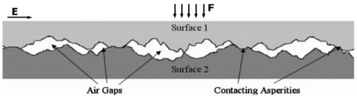
combination of two solid dielectrics causes the formation of voids at the interface due to microscopic imperfections, such as protrusions or contaminants; then the real area of contact between the two solids is smaller than the apparent one. The polymeric interfaces in cable joints are usually made of a soft and an hard material (for example XLPE-EPDM or XLPE-SiR) in order to reduce as much as possible this phenomenon. In any case, the formation of microscopic cavities is unavoidable during the contact between two solid surfaces also because the assembly of system like joints is not done with an automated process under clean room conditions [20; 28].
2.3.1 Mechanism of interfacial breakdown
When the interface is assembled under dry conditions, the cavities are filled with air and, being the dielectric strength of air is much lower than that of the polymeric insulation, the breakdown strength of the voids is necessarily lower comparing to the surrounding bulk insulation one [28]. By using insulating liquid or gel, as mineral oil or silicon grease, before assembling the two dielectrics, the breakdown strength inside the voids could be increased but, in any case, it results to be considerably lower than the bulk insulations one [27]. Therefore, when an electrical field crosses the interface, there is an high risk of partial discharge initiation inside the cavities. In particular, the worst situation arises when an high electrical stress is applied in parallel to the interface, namely when the electric field that crosses the interface is characterized by an high tangential component, considering the interface direction. In fact, looking at figure 2.18,
Fig 2.18: Schematic illustration of a solid-solid interface. The total contact area consists of voids and
the interface can be considered as a string of voids having lower dielectric strength comparing to the contact spots that keep the voids apart. In [21] a model of the interface consisting of a series of connection of spherically shaped voids and contact region is presented, as shown in figure 2.19.
The initiation of partial discharges inside the cavities, on a direction parallel to the interface, is driven by the the tangential electric field. This phenomenon is assumed to be the main mechanism that might lead to the total interfacial breakdown. Indeed, during the partial discharge activity, the breakdown of the gas inside the void causes the slow but gradual degradation and carbonization of the polymeric material of the contact spot, eroding it and releasing conductive materials in the internal boundary of the contact spot. That eroding action determines, in the time, the breakdown across some contact spots. The spot breakdown is also due to a localized electric field enhancement caused by the short circuiting of the voids during the partial discharge action [21; 27]. Hence, a conductive paths starts to bridge the voids along the interface and a complete longitudinal breakdown of the interface is only a matter of time.
Fig 2.19: An electrical model of interfacial breakdown [21].
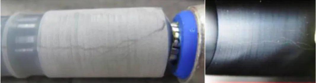
Fig 2.20: Electrical tree formed on the interface between the cable insulation (at left)
It must be underlined that, unluckily, the interface region of cable joints is the point in which the tangential component of the electric field distribution culminates. In fact, even if field grading strategies are adopted ensuring that the electric field crosses the interface as gradually as possible, tangential components of the electric field will be always present, due to the unavoidable particular geometry of the joint. This phenomenon can be appreciated in figure 2.21 where the equipotential lines of a cable joint with geometrical field grading are plotted together with the interfacial electric field stress, split in normal and tangential component. Cable joints with refractive stress control have a similar electric field distribution too [9; 34]. Hence, the problem of interfacial discharges is absolutely a topic that have to be considered in the design and in the installation of cable joints. In particular, it is important to analyze the parameters that affect the interfacial breakdown strength in order to understand how practically manage the harmful phenomenon of interfacial discharges and then recognize the situations in which it is most probable that surface tracking could happen.
Fig 2.21: (a) Section of a prefabricated silicone joint. (b) Equipotential
lines distribution. (c) Normal and tangential electrical stress plot [20; 27].
2.3.2 Parameters affecting the breakdown strength at dielectric interfaces
The latter treatment presented the reason why air-filled cavities are considered to be the preferable starting points for the tangential breakdown paths that propagate along the contact area of two dielectrics. It has also been said that these voids are unavoidably present in hand-made assembled dielectric systems as cable joints are. In order to avoid the arise of partial discharges on the interfacial voids, as mentioned before, the use of insulating liquid or greases while assembling the two dielectrics could increase the breakdown strength inside the cavities, increasing then the ignition voltage of partial discharges. However, two other aspects have to be taken into the account. In particular, to avoid partial discharges, the cavity size has to be kept at the minimum possible, namely the real contact area between the dielectrics should be as large as possible: the real area of contact (and consequently the dimension of the voids) strongly depends on surface roughness and contact pressure at the interface [21; 22]. Hence, also these two parameters affect the breakdown strength of the interfacial voids.
2.3.2.1 Effect of insulating liquid or grease
In practical applications it is common to apply insulating oil or grease over the cable dielectric before the application of the main insulation tube of the joint. This dielectric grease has basically three functions: lubrication, anti-seizing and, mainly, void filling. In fact, in case of rough interfaces, greasing is found to play an important role in eliminating air cavities: filling the voids with liquid insulating material, which has an higher breakdown strength comparing to the air one, improves the dielectric performance of the interface quite a bit. Results from the experimental work [22] show that, in case of sanded surfaces (thus highly rough with many big air voids), greasing has the effect to increase of the 40% the tangential breakdown strength of the interface. Another similar experimental work [32] reported that, by filling the cavities with the application of silicone grease on both the surfaces to be put in contact, the interfaces tends to work as a perfect blend of two bulk dielectric. In fact, the interfacial dielectric
strength is in this case ~2.7 times higher than the one of an interface without silicone grease and, furthermore, it seems to obey to the same law as the one which rules the dielectric strength of bulk EPDM (differently than in case of a dry interface without the grease). In [31], experiments show that the application of silicone grease to the interface leads to retardation of surface discharges and to an increasing in the surface partial discharges inception voltage. Now, it must be considered that greasing may not eliminate all air cavities and that, with aging, the grease tends to dry as a small quantity of oil migrates out of it: small air cavities might arise at the rough interface causing reductions of the interfacial dielectric strength [22]. Also experimental results in [29] show that the grease properties noticeably degrades with aging.
2.3.2.2 Effect of surface roughness
The experimental work [22] investigates the effect of surface roughness on the breakdown voltage of EPDM-XLPE and EPDM-EPDM interfaces considering a tangential AC electric field component applied. The results show that the dielectric strength of smoother interfaces are consistently higher that the one of rougher interfaces due to the presence, in the latter, of more and bigger interfacial voids in which more powerful and harmful dischargers will initiate. Furthermore, it has been reported that the dielectric strength of a smooth EPDM-XLPE interface is higher that that of a smooth EPDM-EPDM interface and, furthermore, it has been argued that possibly this fact is due to the better charge trapping at the XLPE surface [22]. Also in other experimental works [20; 28] the breakdown test performed on dielectric interfaces showed that an increased interfacial roughness results in a reduced interfacial breakdown strength due to the higher peaks and deeper valleys formed in the surface profile leading to the presence of larger cavities at the interface. Even in [19], thanks to the tests performed, it has been concluded that, increasing the interfacial smoothness, the occurrence of oxidation reactions and the formation of carbonization paths at the interface become more difficult and, therefore, the initial discharge voltage, the tracking failure voltage and the time to tracking failure show an increase in comparison to a rougher interface.
Concluding, through the results of the latter studies it is possible to affirm that, in order to improve the performance of the interface created between two polymeric dielectrics, two materials having surfaces as smooth as possible must be used. Consequently, the sanding of the cable dielectric surface in cable accessories should be absolutely avoided. 2.3.2.3 Effect of contact pressure
The effect of the interfacial pressure on partial discharge inception voltage has been investigated experimentally in [18]. In this study, it results that the initial discharge voltage in an XLPE-SiR interface shows an increasing value when the interfacial pressure rises. Furthermore, in this case, the tracking failure needs a longer time to occur. The same phenomenon is observed in [21] where the increase of longitudinal breakdown strength with rising contact pressure is explained to be due to the fact that the diameter of interfacial cavities is expected to significantly decrease by applying higher pressures. In particular, as explained in [27], considering figure 2.18, the effect of an increment of the normal force F is to increase the number of contacts between surface asperities leading to a large contact area for supporting the increasing mechanical force. Consequently, this phenomenon also causes the reduction of interfacial voids dimension: the real area of contact between the two dielectrics is consequently higher. It must be remembered that a decreasing diameter of the cavities restrains the initiation of partial discharges since the inception voltage consequently increases. Hence, the propagation of the consequent carbonization of the contact spots is more difficult with smaller cavities. So, the full breakdown of the interface is expected to be much less likely if higher contact pressure is present.
Also other studies have been made on this field, as [30; 31; 32], always finding that an higher interfacial pressure leads to an higher dielectric strength of the interface. In particular, in [30] EPDM/EPDM and EPDM/XLPE interfaces were tested considering also aging processes; it has been obtained that EPDM/EPDM interfaces seem to maintain dielectric strength with aging much better than the EPDM/XLPE ones. Also in [29] aging tests on EPDM/EPDM and EPDM/XLPE interfaces are performed finding
that the dielectric strength of unaged interfaces is visibly higher than aged ones and arguing that this result could be due to degradation of the interfacial pressure of the interfaces themselves. At last, in [33] XLPE-SiR interfaces are analyzed, emphasizing the fact that the majority of premolded joints are made by silicon rubber: their mechanical performance degrades after operation for several years resulting in the decrease of interfacial pressure and then, as shown in the study, to a decrease of breakdown voltage. Concluding this speech, it must be paid much attention during the installation of cable joints, especially the heat shrink ones, in order to avoid the loss of interfacial pressure. The more care is taken in the joint insulation installation, the more is lengthened the life-span of cable joints, avoiding premature interfacial breakdowns. 2.3.3 Considerations about cable joint installation
Summarizing what it has been just presented, the breakdown strength of a dielectric interface increases if:
• the applied pressure increases;
• smoother dielectric surfaces are used;
• the voids at the interface are filled with insulating liquid or grease.
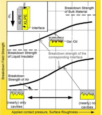
Hence, also as concluded in [31], tightly fitted, smoothed and dry interfaces equipped with a layer of silicon grease have the best performance, as it can be seen also from figure 2.22. In particular, this diagram refers to an XLPE-XLPE interface but, in any case, the graph trend is expected to be the same also for XLPE-SiR or XLPE-EPDM interfaces thanks to the results found in the different studies explained before. The graph shows that, in case of absence of insulating grease, the breakdown strength of the interface is always higher that that of air but not as strong as the bulk material strength, even under very high contact pressure and surfaces smoothness. However, as also underlined in [20], interfaces could perform similarly as the bulk materials when an insulating grease is present, the applied pressure is high and the the contact surface is as smooth as possible. Thus, concluding, during the installation of power cable joints much
care must be taken in smoothing interfaces as much as possible, in applying an uniform grease layer and in performing a good tightening of the shrinkable joint tubes. The attention on the respect of these actions by the jointers is then fundamental: from the care taken in the installation of the interface depends the strength of the cable joint from harmful interfacial partial discharges.
Obviously, jointers must be also careful in avoiding the ingress of contaminants as water or dust that could possibly fall on the interface during the installation. In fact the existence of water droplets or conductive particles at the interface cause a strong reduction in the breakdown strength of the insulation system being extremely easier, in this case, the formation of a conductive path that bridges the high voltage electrode and the ground electrode of the joint.
Fig 2.22: Tangential breakdown strength of interfaces versus applied


![Fig 2.11: Heat shrink medium voltage cable joint [9].](https://thumb-eu.123doks.com/thumbv2/123dokorg/7411125.98358/31.892.155.748.187.348/fig-heat-shrink-medium-voltage-cable-joint.webp)