Curriculum in Ingegneria Industriale
Microgrid scale Liquid Air Energy
Storage: plant optimization and
thermal characterization of phase
change materials for High Grade
Cold Storage
Ph.D. Dissertation of:
Emiliano Borri
Advisor:
Prof. Gabriele Comodi
Coadvisor:
Asst. Prof. Alessandro Romagnoli
Curriculum in Ingegneria Industriale
Microgrid scale Liquid Air Energy
Storage: plant optimization and
thermal characterization of phase
change materials for High Grade
Cold Storage
Ph.D. Dissertation of:
Emiliano Borri
Advisor:
Prof. Gabriele Comodi
Coadvisor:
Asst. Prof. Alessandro Romagnoli
Facoltà di Ingegneria
Acknowledgments
I would like to express my gratitude to my supervisor Prof. Gabriele Comodi for offering me this experience. I’m glad to have had this research opportunity which has contributed significantly to expand my knowledge and gave me the opportunity to study around the world. I would like to thanks to my mentor Prof. Giovanni di Nicola that first introduced me to the scientific research and gave me precious advice before to start this experience. Thanks also to Dr. Alessandro Romagnoli to welcoming me at the Nanyang Technological University of Singapore and gave me the opportunity to collaborate with your team. With your support, I had the opportunity to dress a lab coat and carry out a huge part of my work.
Many thanks also to Dr. Yongliang Li to gave me the opportunity to spend time with his group at the University of Birmingham. I’m glad to have been part of your team in the place where the research on liquid air energy storage began. Alessio, I’m glad for collaborating on this project with you, we spent a lot of effort together and we become good friends since the beginning. The destiny wanted that we were also flatmates but that’s another story.
Thanks, Jia Yin for your kindness and your support. During my Ph.D., it was a pleasure to collaborate in the NTU lab with you. Out of the work, you are my mentor of the Singaporean culture and I’m glad for being welcomed in your wonderful family and feel like your Italo-Singaporean nephew.
Thanks, Andrea and Francesco, colleagues and good friends since I’ve started university. It was amazing to be part of the same group during our Ph.D. and share beautiful moments together in and out of the work. Thank you, Michele, I hope I was a good co-advisor for your thesis. I would like to thanks also Manuel, Stefano, Haoxin, Fadhel and all the NTU team for the support. Thanks also to my greek mate Argyris, Lucia, Marco, Serena, Rob and all the Birmingham friends. Thank you, Matteo, with which I’ve started my Ph.D. I’ve always admired your strength and your effort in science, and I wish you a brilliant career. Thanks also to all the "PhD and more" lunch crew.
I would like to thanks my Ph.D. friend and old flatmate "Liutone" for his support and his precious advise every time I need to do choice. Thank you Marco Sbaragna and Sir Alberto to always support me even at a distance while I was abroad. Thank you, Marco, since we have met in Istanbul, you always influenced me with your positivity.
part of my life. Henny, our passion for the music started an amazing friendship and a lot of adventures together.
Thank you for your positive vibes and your support. Tommy Padang, if Singapore was an amazing experience it was also thanks to you. Thank you for welcoming me in the Nobel House and for your support. I hope that the Bidlis will tour again together in another part of the world. I would like to thanks also all the "Nobel Ladies" Trini, Valentina and Erica to stand me and Tommy together. I would like to thanks all the "Penangians": Peppe Panjang, Maurizio Pasir, Fabio Villa, Paolo Ban Mian, Ramesh, Pierre Baynan and FrancescoGelly. Thanks, Yunus to let me win Tavla just once. Thank you, Sumida, Ana Maria, Prachi, Rahul, Vani, Shaun, Jereon, Kim, Federico, Claudia, Rahul, Ania, Michele, Ezequiel and all the people that I’ve met in Singapore with which I’ve spent beautiful moments. Thanks also to the Tanglin Blues Club to have played together some good music. Last but not least thanks to my family for your support and patience.
Ancona, Novembre 2018
Abstract
The increasing of the energy consumption related to the global energy demand is the main cause of environmental issues, such as greenhouse effect and cli-mate change. The new policies related to the energy sector are aiming to a deep decarbonization of the grid that has led to reducing the energy produced from fossil fuels increasing the penetration of renewable energy sources in the actual energy system. The main drawback of clean energy sources is related to their unpredictable nature. The new challenge of the energy sector is then to overcome the problem related to the intermittency of renewable sources op-timizing the balance between energy supply and energy demand. The use of energy storages has a fundamental role to guarantee the flexibility of the en-ergy system capturing the wrong-time power from the renewables giving the possibility to be used in a later time or in a different place.
The large amounts of cold thermal energy wasted (from spare liquid nitrogen and LNG regasification) and the research of a new and sustainable energy vector have led to study the potential of cryogens on grid, transport and cooling applications defining a possible "liquid air economy". In the grid context, Liquid Air Energy Storage (LAES) is based on the concept that air at ambient pressure can be liquefied at -196°C, reducing the specific volume of around 700 times, to be stored in low-pressure vessels. The liquid air then can be expanded in a later time in a power producing device (e.g. turboexpander, reciprocating engine) to produce electric power.
The first concept son using the liquid air as storage medium was proposed in 1977 and again in the early 2000 but with no further developments. In 2005 University of Leeds and Highview Power patented a LAES system with a lique-faction system based on a Linde-Hampson cycle. The research starting from lab scale components has led to develop a 300kW/2.5MWh LAES pilot plant. The plant initially commissioned in April 2010 was located at Scottish and South-ern Energy 80MW biomass plant at Slough Heat and Power in Greater London and now relocated at the University of Birmingham. In the recent years, the realization of the first pilot plant and the demonstration of the potential of cryogens as an energy vector, have led the LAES to attract the attention of many researchers due to their several advantages, such as long lifetime and no geological constraints. Furthermore, LAES can be easily scalable to large size due to the system made with existing mature components and sustainable
ma-LAES feasibility, is the low round-trip efficiency that is estimated around 50-60 % for large-scale systems. The most of the interest in the literature available is dedicated to industrial scale systems (up to 300 tons per day) to compete with large-scale technologies used for medium or long-term storage such as com-pressed air energy storage (CAES) and pumped hydroelectric (PHE). However, although a large portion of electric power produced still realize on large central-ized systems, the energy system is moving towards to a decentralcentral-ized energy production system with distributed energy resources (DER) and microgrids. The potential of the LAES technology and the related advantages make it in-teresting to investigate a small-scale (microgrid scale) that can be suitable for DER and microgrid applications as a medium or long-term energy storage.
In this work, a microgrid scale LAES is proposed defining a system that in-tegrates a liquefaction plant with a daily production ranging between few tons and few tens of tons of liquid air. The aim of this work is to start the challenge of scaling down and reduce the size of the LAES contributing to the scientific community to understand the potential of this technology and inspire future research.
The first part of this thesis analyzes different liquefaction cycles, suitable for small-scale LAES with the aim to find an optimal configuration that minimizes the specific consumption of the plant. Indeed, the liquefaction cycle mainly affects the roundtrip efficiency of the system. The analysis, done by software simulation Aspen HYSYS, is based on parametric analysis and a comparison between the liquefaction cycles. A Kapitza cycle configuration with a two-stage compression working at supercritical pressures (over 40 bar), is the best cycle configuration that, if integrated to a pressurized phase separator, can achieve a specific consumption below 500 kWh/t. Furthermore, the high exergy loss at the compressor aftercoolers suggests that the integration of a waste heat recycle can increase the exergy efficiency of the system. Combining the system with a 105.5 kW single-effect water-Lithium Bromide absorption chiller the specific consumption of the microgrid scale LAES liquefier can be reduced of around 10%.
In the second part of the work, the Kapitza cycle has been integrated into a complete configuration of a microgrid LAES system that includes both the discharge section and the waste heat and cold thermal energy recovery system. A wide range of operating conditions has been assumed to evaluate the effect on the system performance. The results have been used to elaborated four performance maps to be used as a simple and immediate method that can be applied by engineers and researcher to estimate the LAES performance and optimize the design in terms of term of specific consumption, specific electric
The performance maps highlight that the reuse of the cold energy released by the liquid air before the expansion in the discharge cycle allows to improve the performance of the charge side of the LAES decreasing the specific consump-tion of the liquefacconsump-tion cycle and increase the overall roundtrip efficiency of the system. Therefore, the last part of the thesis focuses on the High Grade Cold Storage (HGCS) that represents the main component of the waste cold recovery system. HGCS is fundamental to improve the performance the microgrid LAES and decrease the specific consumption of the liquefaction plant. To reduce the dimension of the storage increasing the energy density, a hybrid HGCS solution that integrates one or more part of phase change materials (PCM) has been proposed to improve the actual bulky solutions based on a sensible heat storage. The hybrid HGCS is part of a project based at TESLAB@NTU in the Nanyang Technological University of Singapore. The design of the storage using PCM requires a good understanding of the thermal behaviour of the storage medium during the charging and the discharging. Therefore, this work focuses on the thermal response and thermal characterization of PCM proposing a methodol-ogy to measure and predict the thermal behaviour of low temperature PCM. In particular, an experimental rig has been designed to measure the tempera-ture in different points of a PCM placed inside a cylindrical shape container. The results are then used to validate a simple 1-D model that can be used to predict the thermal behaviour of different low temperature PCM. For this purpose, the container has been designed to obtain a similar thermal behaviour of the PCM involving a one-dimensional heat transfer process. The 1-D model has been calibrated and validated with the experimental results obtained with the melting and the solidification of pure deionized water. The reliability of the results has been verified with two different tests evaluating the solidifica-tion and the melting in different posisolidifica-tions of the container. The methodology has been tested with a solution with a concentration of 30% of ethylene glycol (EG30) by weight in deionized water. Although aqueous alcohols are difficult to test due to their low latent heat and slow nucleation rate, the results of the 1-D model shows a good agreement with the experimental data representing a valid and simple method to approximate and predict the time of charge and discharge of the PCM and to compare the thermal profiles of different materi-als. Furthermore, the simplicity of the code allows the numerical model to be integrated into a more complex numerical model, particularly suitable for the complete modelling of HGCS.
Sommario
L’incremento del consumo energetico legato ad un forte aumento della do-manda energetica mondiale, rappresenta la principale causa delle attuali prob-lematiche ambientali legate al riscaldamento globale, come l’effetto serra e il cambiamento climatico. Le nuove politiche del settore energetico mirano ad una radicale decarbonizzazione della rete che ha notevolmente ridotto la pro-duzione energia prodotta da fonti fossili, incrementando la penetrazione delle fonti rinnovabili. Il maggiore svantaggio di queste ultime è legato alla loro in-termittenza e alla loro imprevedibilità. I nuovi obiettivi del settore energetico, sono quindi focalizzati nel risolvere le problematiche legate alle fonti rinnovabili e l’ottimizzazione del bilancio tra potenza prodotta e la domanda energetica. L’integrazione di sistemi di accumulo (energy storage) risulta quindi fonda-mentale per garantire la flessibilità del sistema energetico. Infatti questi ultimi hanno la capacità di accumulare la potenza elettrica per essere utilizzata in un tempo successivo.
Le grandi quantità di energia termica a temperatura criogenica dissipate nell’ambiente durante la rigassificazione del GNL (gas naturale liquefatto) e i grandi volumi di azoto liquido prodotto non utilizzato, hanno suggerito lo studio dei liquidi criogenici come vettori energetici alternativi che possono uti-lizzati sia essere mezzi di stoccaggio, ma anche applicati nel settore dei trasporti definendo una "liquid air economy". In questo contesto i sistemi LAES (Liquid Air Energy Storage) rappresentano un sistema di accumulo basato sul concetto che l’aria ambiente può essere liquefatta a -196°C riducendo il suo volume speci-fico di circa 700 volte, ed essere stoccata in serbatoi a bassa pressione. L’aria liquida può essere quindi utilizzata nuovamente, per produrre potenza elettrica mediante un espansore.
Alcune idee per utilizzare l’aria liquida come mezzo di stoccaggio sono state proposte nel 1977 e nei primi anni 2000, ma senza ulteriori sviluppi. Nel 2005 University of Leeds e Highview Power hanno brevettato un sistema LAES con un ciclo di liquefazione basato su un ciclo Linde-Hampson. Il progetto di ricerca ha portato allo sviluppo e alla realizzazione di un impianto pilota LAES con una potenza di 300 kW e una capacità di stoccaggio di 2.5 MWh. L’impianto, commissionato ad Aprile 2010, è stato inizialmente integrato con un impianto a biomasse di 80MW locato allo Slough Heat and Power di Greater London e successivamente rilocato a University of Birmingham. Negli ultimi anni, grazie
dei liquidi criogenici come vettori energetici, il LAES è diventato oggetto di interesse di molti ricercatori grazie ai diversi vantaggi che la tecnologia offre, come la durata dell’impianto e l’assenza di vincoli ambientali. Inoltre il LAES può essere facilmente scalabile, grazie alla consolidata tecnologia basata su componenti già utilizzati in ambito criogenico. Il maggiore svantaggio, che compromette la fattibilità dei sistemi LAES, è la bassa efficienza che può essere stimata del 50-60 % per sistemi di larga scala. La maggior parte dell’interesse in letteratura è dedicato a sistemi di scala industriale con un ciclo di liquefazione basato su una produzione giornaliera di aria liquida maggiore di 300 tonnellate. Questi sistemi sono studiati per competere con i sistemi di accumulo energetico di larga scala di medio o lungo periodo come gli storage ad aria compressa (CAES) o i sistemi di accumulo con pompaggio di acqua (PHE).
Sebbene ancora una grande porzione di potenza elettrica viene prodotta da grandi sistemi centralizzati, negli ultimi anni il sistema energetico mondiale si sta muovendo verso sistemi decentralizzati con le sorgenti di generazione distribuita (DER) e le microgrids. Il potenziale della tecnologia LAES e i suoi vantaggi, rendono interessante lo studio di un LAES di piccola scala (microgrid scale LAES) che può essere dedicato come sistema di accumulo di medio o lungo periodo per applicazioni di generazione distribuita e microgrid.
In questa tesi il microgrid scale LAES è stato proposto definendo un impianto che integra un ciclo di liquefazione con una produzione giornaliera di aria liquida da poche tonnellate a poche decine di tonnellate al giorno. L’obiettivo di questo lavoro è quello di intraprendere la sfida nel ridurre la scala di un sistema LAES contribuendo alla comunità scientifica a definirne le potenzialità e ispirare la ricerca a possibili lavori futuri.
La prima parte di questa tesi analizza diversi cicli di liquefazione, adatti per essere applicati ad un LAES di piccola scala, con l’obiettivo di trovare una con-figurazione ottimale che minimizza il consumo specifico. Il confronto dei diversi cicli di liquefazione è stato basato su una analisi parametrica eseguita tramite il software di simulazione Aspen HYSYS. Un ciclo Kapitza supercritico (oltre 40 bar) con un doppio stadio di compressione, risulta la migliore configurazione e, se integrato ad un serbatoio di aria liquida pressurizzato, il consumo specifico stimato può essere inferiore ai 500 kWh/t. Inoltre, l’analisi exergetica, eviden-zia una grande porzione di exergia persa durante l’interrefrigerazione tra i due stadi di compressione che suggerisce l’integrazione di un sistema di recupero dell’energia termica ad alta temperatura. Combinando il ciclo di liquefazione con un ciclo ad assorbimento a singolo effetto basato su un ciclo con acqua e bromuro di litio (LiBr), il consumo specifico del microgrid scale LAES può essere ridotto del 10%.
sezione di scarica, che i sistemi di recupero dell’energia termica ad alta e bassa temperatura. Una analisi parametrica del sistema è stata eseguita assumendo un’ ampia variazione delle condizioni operative del sistema valutandone l’effetto nelle prestazioni e nell’efficienza finale. I risultati, sono stati usati per elaborare quattro mappe di performance. Queste possono essere usate come un semplice strumento che può essere usato per stimare l’efficienza del sistema LAES e trovare le configurazioni ottimali che migliorano il consumo specifico, la potenza prodotta e l’efficienza globale dell’impianto.
Lo storage termico a bassa temperatura o "High Grade Cold Storage" (HGCS) è il componente principale del sistema di recupero di energia termica a bassa temperatura che risulta fondamentale per migliorare le prestazioni del micro-grid LAES e diminuire il consumo specifico del ciclo di liquefazione. Per ridurre le dimensioni del sistema di accumulo termico incrementando la densità ener-getica, una soluzione di HGCS ibrida è stata proposta in questo lavoro. Lo storage ibrido è parte di un progetto basato al TESLAB@NTU nella Nanyang Technological Uuniversity di Singapore, e prevede l’integrazione di una o più parti di materiali a cambiamento di fase (PCM) nelle attuali soluzioni di HGCS basate su sistemi di accumulo termico a calore sensibile.
Il design dei sistemi di accumulo termico che utilizzano PCM, richiedono la conoscenza del comportamento termico del mezzo di stoccaggio durante le fasi di carica e scarica. Questa tesi si focalizza nella caratterizzazione termica dei materiali a cambiamento di fase a bassa temperatura, proponendo una metodologia che può essere utilizzata per misurare e prevedere il comporta-mento termico dei PCM.
In particolare un apparato sperimentale è stato progettato per misurare la temperatura in differenti punti di un PCM contenuto in un contenitore cilin-drico. I risultati sono stati quindi usati per validare un semplice modello 1-D che può essere utilizzato per prevedere il comportamento termico di PCM a bassa temperatura. Per questo obiettivo, il container è stato progettato per ottenere dal PCM un comportamento simile ad un processo di trasferimento di calore monodimensionale.
il modello 1-D è stato calibrato e validato con i risultati sperimentali ottenuti con la carica e la scarica di acqua deionizzata. L’attendibilità dei risultati è stata verificata con due test differenti, valutando la solidificazione e lo sciogli-mento in differenti punti del container. La metodologia è stata quindi testata con diverso PCM basato una soluzione di glicole etilenico (EG) dissolta con una concentrazione del 30% in acqua pura. Le soluzioni alcoliche acquose risul-tano difficili da testare a causa del basso valore di calore latente (o entalpia di fusione) e la bassa velocità di nucleazione. I risultati ottenuti con il modello 1-D, mostrano una buona corrispondenza con i dati sperimentali. Il metodo
e prevedere il tempo di carica e scarica di diversi PCM e confrontare i dif-ferenti comportamenti. Inoltre, la semplicità del codice numerico, permette a quest’ultimo di essere facilmente integrato in modelli numerici più comp-lessi ed essere utilizzato per un modello completo dello storage termico a bassa temperatura.
Contents
1. Introduction 1
1.1. Energy storage classification . . . 2
1.2. Introduction to LAES . . . 3
1.2.1. History of the LAES . . . 6
1.2.2. LAES and the "liquid air economy" . . . 9
1.2.3. Literature review of LAES . . . 10
1.3. Microgrid scale LAES and aim of this work . . . 13
2. Preliminary study on a microgrid scale LAES air liquefaction plant 17 2.1. Optimal configuration of microgrid LAES liquefaction plant . . 18
2.1.1. Introduction to the air liquefaction cycles . . . 18
2.1.2. Materials and methods . . . 19
2.1.3. Results . . . 24
2.2. Effect of the phase separator/air liquid tank pressurization . . 35
2.2.1. Discussion and optimal congifuration proposed . . . 38
2.3. Improving liquefaction of microgrid LAES . . . 39
2.3.1. Materials and Methods . . . 40
2.3.2. Results . . . 44
2.4. Discussion and main findings . . . 46
3. Parametric performance maps for microgrid scale LAES 49 3.1. Materials and methods . . . 50
3.1.1. Microgrid scale LAES charge section . . . 50
3.1.2. Microgrid scale LAES discharge section . . . 51
3.1.3. Simulation Assumptions . . . 52
3.2. Results and discussion . . . 55
3.2.1. Effect of charge pressure and waste cold power on the Specific consumption . . . 55
3.2.2. Charge pressure-TIT relation . . . 58
3.2.3. Discharge pressure-TIT relation . . . 59
3.2.4. Round trip efficiency evaluation . . . 60
3.3. Use of the performance maps . . . 61
3.3.1. Example A: High-pressure liquefaction system and medium efficiency of HGCS and HGWS . . . 61
3.3.2. Example B: Low-pressure liquefaction system and
medium-high efficiency of HGCS and HGWS . . . 64
3.4. Discussion and main Findings . . . 66
4. Thermal characterization of PCM for HGCS: Introduction and Methods 67 4.1. Introduction and background . . . 67
4.1.1. HGCS and Cold Thermal Energy Storage . . . 68
4.1.2. Layout design of HGCS . . . 71
4.1.3. Use of PCM in the LAES HGCS . . . 72
4.1.4. Overview of Low Temperature PCM . . . 74
4.1.5. Design of hybrid HGCS . . . 77
4.1.6. Aim of this work . . . 79
4.2. Materials and Methods . . . 80
4.2.1. Experimental Rig . . . 80
4.2.2. Material selection and Properties characterization . . . 82
4.2.3. Experimental Setup . . . 87
4.3. 1-D Numerical Model . . . 91
4.3.1. Introduction to phase change numerical characterization 91 4.3.2. Simulation assumptions . . . 95
4.3.3. Calibration of the 1-D Model . . . 97
5. Thermal characterization of PCM for HGCS: Results 101 5.1. Experimental Results . . . 102
5.1.1. EG30: Material Characterization . . . 102
5.1.2. Thermal Response of Deionized Water . . . 104
5.1.3. Thermal Response of Aqueous ethylene glycol 30% in DI water (EG30) . . . 108
5.2. Calibration of the 1-D Model . . . 111
5.3. Validation and test of the methodology . . . 114
5.3.1. Validation with pure DI water . . . 114
5.3.2. Test on Aqueous EG . . . 125
5.4. Discussion and main findings . . . 136
6. Conclusions and suggestions for future works 139 6.1. Summary of main conclusions . . . 139
6.2. Future works . . . 145
A. LAES performance maps 149 B. Nomenclature 155 B.1. Latin Symbols . . . 155
B.2. Greek Symbols . . . 156 B.3. Subscripts . . . 157 B.4. Acronyms . . . 158
List of Figures
1.1. Classification of energy storage by function, Chen et al. 2009 . 2 1.2. Schematic of a stand-alone LAES . . . 4 1.3. Schematic of the cryogenic energy storage proposed by Smith . 7 1.4. Highview power LAES pilot-plant located at university of
Birm-ingham . . . 8 1.5. Industrial park intergrating LAES, Centre for Low Carbon
Fu-tures 2013 . . . 10 1.6. Estimated cost of LAES based on the size of the plant . . . 13 1.7. Small-scale LAES integrated to a Microgrid . . . 14 2.1. Schematic of the Linde-Hampson liquefaction cycle . . . 19 2.2. Schematic of Claude liquefaction cycle . . . 20 2.3. Schematic of Kapitza liquefaction cycle . . . 20 2.4. Specific Consumption of the Linde-Hampson cycle at different
operating pressures . . . 24 2.5. Specific consumption of Claude cycle with one stage compression
at different operating pressures . . . 25 2.6. Specific consumption of Claude cycle with two stage compression
at different operating pressures . . . 26 2.7. Specific consumption of Kapitza cycle with one stage
compres-sion at different operating pressures . . . 27 2.8. Specific consumption of Kapitza cycle with two stage
compres-sion at different operating pressures . . . 27 2.9. Plots of the temperature profile of the Heat Exchangers
HEX-1(a, c) and HEX-2 (b,d) of Kapitza cycle with two stage com-pression for 10 bar and 0.1 of recirculation fraction (a,b) and for 40 bar and 0.2 of recirculation fraction (c,d) . . . 28 2.10. Plots of the Heat Exchanger HEX-1 and HEX-2 profile of Kapitza
cycle with two stage compression for 40 bar operating pressure and 0.1 of recirculation fraction . . . 29 2.11. Total air mass flow rate, Two stage compressor power,
Cryotur-bine power and specific consumption of the two stage compres-sion Kapitza cycle for an operating pressure of 40 bar . . . 30
2.12. Liquid Yield of the two stage compression Kapitza cycle for an operating pressure of 40 bar . . . 31 2.13. Comparison of the specific consumption of Claude and Kapitza
cycles with two stage compression at different operating pres-sures . . . 31 2.14. Heat exchangers temperature profiles of the two stage
compres-sion Claude cycle . . . 33 2.15. Exergy efficiency of the Linde, Kapitza and Claude liquefaction
cycles . . . 34 2.16. Schematic of the compressor stage of the Kapitza liquefaction
cycle with pressurized phase separator . . . 35 2.17. Specific consumption of Kapitza cycle at different phase
separa-tor pressures . . . 37 2.18. compression phase of the Kapitza cycle with pressurized phase
separator with absorption chiller integrated . . . 40 2.19. Schematic of the absoprtion chiller . . . 41 2.20. Results of the characteristic equation method and the
parame-ters used for equation 2.9 and 2.10 applied for a 105.5 kW single stage water-Li-Br absorption chiller . . . 44 3.1. Schematic of LAES charge section . . . 50 3.2. Schematic of LAES discharge section . . . 51 3.3. methodology used for the performance maps . . . 54 3.4. Effect of charge pressure and waste cold recovery efficiency on
specific consumption for different optimum values of recircula-tion fracrecircula-tion . . . 55 3.5. Energy balance over the control volume . . . 57 3.6. Qtot,HGCS as a function of discharge pressure . . . 57
3.7. Effect of charge pressure and waste heat recovery on the turbine inlet temperature . . . 58 3.8. Effect of discharge pressure and Turbine Inlet Temperature on
the specific electric power output . . . 59 3.9. Round trip efficiency as a function of net Electric power output
and liquefaction specific consumption . . . 60 3.10. Example A: evaluation of the specific consumption . . . 61 3.11. Example A: evaluation of the TIT . . . 62 3.12. Example A: of the specific electric power . . . 62 3.13. Example A: Calculation of the round trip efficiency . . . 63 3.14. Example B: Calculation of the key performance indicators from
the main operative parameters . . . 65 4.1. Schematic of the components of LAES high grade cold recycle . 68
4.2. Figure CTES for sub-zero applications . . . 69 4.3. sensible heat HGCS and hybrid HGCS . . . 74 4.4. PCM materials compared with their melting temperatures . . . 75 4.5. Classification of low temperature PCM . . . 75 4.6. Eutectic diagram for eutectic salts . . . 76 4.7. Gannt diagram of TESLAB@NTU Activity . . . 80 4.8. Schematic of the Experimental Rig . . . 81 4.9. PCM container and main dimensions . . . 82 4.10. Thermocouple position in the PCM container . . . 83 4.11. Assembly of the container . . . 88 4.12. Charging of the PCM in the cold thermal bath . . . 90 4.13. Discharging of the PCM in the cold thermal bath . . . 90 4.14. Thermal resistance of the container . . . 96 4.15. PCM container with a single thermocouple for the methodology
validation . . . 97 5.1. Experimental results of DSC measurements for aqueous ethylene
glycol (30%) . . . 102 5.2. Thermal conductivity of aqueous ethylene glycol (30%)
calcu-lated from the LFA results . . . 103 5.3. Charge - solidification of pure DI water in different in position
A,B,C,D . . . 105 5.4. Discharge - melting of pure DI water in different in position A,
B, C, D . . . 107 5.5. Charge - solidification of EG30 in different in position A,B,C,D 109 5.6. Discharge - melting of EG30 in different in position A,B,C,D . 110 5.7. Experimental and numerical results of solidification of DI water 113 5.8. Numerical simulations of DI water in different positions . . . . 113 5.9. Experimental and numerical results of melting of DI water . . . 114 5.10. Experimental and numerical results for the charging-solidification
of DI water in position A . . . 115 5.11. Experimental and numerical results for the charging-solidification
of DI water in position B . . . 116 5.12. Experimental and numerical results for the charging-solidification
of DI water in position C . . . 117 5.13. Experimental and numerical results for the charging-solidification
of DI water in position D . . . 118 5.14. Experimental and numerical results for the discharging-melting
of DI water in position A . . . 119 5.15. Experimental and numerical results for the discharging-melting
5.16. Experimental and numerical results for the discharging-melting of DI water in position C . . . 121 5.17. Experimental and numerical results for the discharging-melting
of DI water in position D . . . 122 5.18. Experimental and numerical results for the charging-solidification
of EG30 in position A . . . 126 5.19. Experimental and numerical results for the charging-solidification
of EG30 in position B . . . 127 5.20. Experimental and numerical results for the charging-solidification
of EG30 in position C . . . 128 5.21. Experimental and numerical results for the charging-solidification
of EG30 in position D . . . 129 5.22. Experimental and numerical results for the discharging-melting
of EG30 in position A . . . 130 5.23. Experimental and numerical results for the discharging-melting
of EG30 in position B . . . 131 5.24. Experimental and numerical results for the discharging-melting
of EG30 in position C . . . 132 5.25. Experimental and numerical results for the discharging-melting
of EG30 in position D . . . 133 A.1. Effect of charge pressure and waste cold recovery efficiency on
specific consumption for different optimum values of recircula-tion fracrecircula-tion . . . 150 A.2. Effect of charge pressure and waste heat recovery on the turbine
inlet temperature . . . 151 A.3. Effect of discharge pressure and Turbine Inlet Temperature on
the specific electric power output . . . 152 A.4. Round trip efficiency as a function of net Electric power output
List of Tables
1.1. Specific Consumption of the Highview Pilot Plant and Commer-cial Scale LAES . . . 6 2.1. Boundary conditions for Linde, Claude and Kapitza cycles
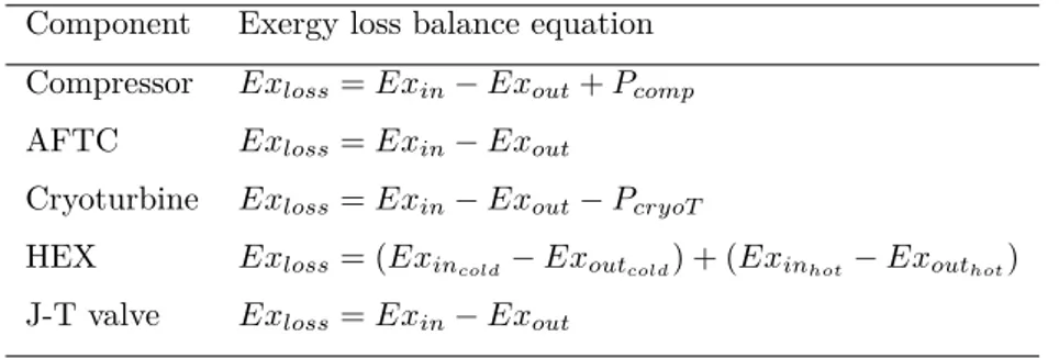
sim-ulations . . . 22 2.2. Exergy loss equations for each component of the liquefaction cycle 24 2.3. Summary of the optimal operating conditions range for two stage
compression cycles . . . 32 2.4. Exergy loss in the components of the Kapitza cycle with two
stage compression operating at 40 bar and 0.2 of recirculation fraction . . . 35 2.5. Boundary conditions for the simulations of the Kapitza cycle
with pressurized phase separator . . . 36 2.6. Optimal operating parameters for the Kapitza cycle . . . 39 2.7. Boundary conditions for the simulation of the Kapitza cycle with
pressurized phase separator (PS) with absorption chiller (Abs) and without heat recovery . . . 43 2.8. Results of the simulations for Kapitza cycle with pressurized
phase separator (PS) with absorption chiller (Abs) and without heat recovery . . . 45 3.1. Operative parameters and key performance indicators used for
the parametric analysis . . . 53 3.2. Value and range of the operative parameters used for the LAES
parametric analysis . . . 54 4.1. Main characteristics of subzero PCM categories . . . 85 4.2. Temperatures of cold and warm thermal bath used for the tests 87 4.3. Film temperature warm and cold bath properties used for the
heat transfer convection coefficient calculation . . . 99 5.1. Thermal conductivity of aqueous ethylene glycol (30%) . . . 103 5.2. DI water properties used for the 1-D numerical model . . . 111 5.3. RMSE value of the 1-D model for discharging-melting of pure
5.4. properties for Aqueous Ethylene Glycol (30%) used for the 1-D numerical model . . . 125 5.5. RMSE value of the 1-D model for discharging-melting of EG30 134
Chapter 1.
Introduction
Energy is part of our all-day life. The rising number of developing countries and the growth of population has led our society to become strongly dependent on energy sources with an increase the global energy demand. EIA reports that from the year 2015 the world energy consumption is expected to increase of 28% until 2040[1]. Nowadays, the energy consumption is the major contribu-tion of the greenhouse effect accounting the 80% of CO2 emissions with the energy produced by fossil fuels that still accounts the fourth-fifth of the to-tal energy production[2]. The policies related to environmento-tal sustainability, energy security, and climate change are leading to a radical transformation of the energy sector aiming to achieve a deep decarbonization of the grid. The strongest evidence of the energy transition is represented by the shifting of the energy production from fossil fuels towards to clean and sustainable sources of energy. In 2016, renewables represent the 18.2% of the energy production with an increase of the generating capacity in 2017 by 9% over 2016[3]. The cost of solar photovoltaics and wind systems had a rapid decrease in the last few years and today accounts the main power capacity additions to the grid. The main challenge of a low carbon network is to design an energy system able to support a high penetration of renewable energy sources (REs). One of the main drawback related with the REs is their “non-dispatchable” behav-ior due to their unpredictable nature that generates a mismatch between the power supply and power demand. Capturing the wrong-time power from the renewables with the use of energy vectors, the energy can be stored and used in a later time or different place. In this context, the integration of energy storage (either thermal or electrical) has a fundamental role to overcome those challenges and guarantee the flexibility of the energy system. Strbc [4] high-lights the importance of energy storage in shaping the energy demand in the context of the "demand side management", where they can use in peak shaving or load leveling strategies. Indeed, the wrong time energy stored can be used, for example, to cover the energy demand during the peak periods that would be otherwise displaced by the fossil fuels.
1.1. Energy storage classification
According to Chen et al.[5], electrical energy storages (EEs) can be classified with two different criteria: function and form. In terms of function storages can be divided (Figure 1.1) in storages suitable for high power ratings (to guarantee power quality) and storage that can be used for energy management. The classification by from can divide EEs into:
• Electrical energy storage
– Electrostatic energy storage (Capacitors and supercapacitors) – Magnetic/current energy storage
• Mechanical energy storage – Kinetic energy storage – Potential energy storage • Chemical energy storage
– Electrochemical energy storage (batteries) – Chemical energy storage (fuel cells) – Thermochemical energy storage • Thermal energy storage
– Low temperature energy storage (Aquiferous cold energy storage, cryogenic energy storage)
– High temperature energy storage (sensible heat systems such as steam or hot water accumulators, graphite, hot rocks and concrete, latent heat systems such as phase change materials)
In order to balance the gap between energy supply and energy demand, the traditional solutions rely on the use of hydro plants [6], suitable for a grid with a small number of large power plants. The decentralization of energy production and the increasing number of small power plants affects the needs of more
flexible and sustainable systems. In this case, the chemical energy storages such as batteries and fuel cells, are able to provide high storage efficiency, but they are costly and their lifetime (10-15 years) is shorter compared to other storage technologies. When the storage life is over, the materials need to be recycled and processed increasing the economic and the environmental costs. Nowadays, two mature solutions, sustainable and long lifetime is represented by Pumped Hydro (PHE) and Compressed Air Energy Storage (CAES). PHE can be classified in the category of mechanical/potential energy storage; in those systems, water is pumped from two different reservoirs at two different height levels. When the power is needed, the potential energy of the water at the higher level is converted into electrical energy by means of a turbine. Those systems can achieve an efficiency of around 70-80 % [6]. On the other hand, CAES uses the low-cost or wrong time power to produced compressed air to be stored in pressurized vessels located in underground caverns. The compressed air is then heated using natural gas or waste heat sources and expanded in a turbine to generate electricity. A thermodynamic analysis conducted by Grazzini et al. [7]on a CAES system shows that it is possible to achieve a round trip efficiency of 72% if the heat generated during the compression is recovered and reused during the discharge phase. The main disadvantage that strongly limits the applicability of those two technologies, is represented by the geographical constraints. An alternative to CAES and PHE is represented by Liquid Air Energy Storage (LAES) systems that use cryogens as the energy vector.
1.2. Introduction to LAES
LAES is based on the concept that air at ambient pressure can be liquefied at -196°C, reducing the specific volume of around 700 times, to be stored in unpressurized vessels. The liquid air then can be expanded in a later time in a power producing device (e.g. turboexpander, reciprocating engine) to produce electric power. The potential of the high grade cold thermal energy as energy vector is investigated by Li et al.[8] that proposed four different systems based on Rankine and Brayton cycles to efficiently use the energy from cryogens. Indeed the use of liquid air allows operating with an energy vector with a higher energy density compared with the compressed air (150-250 Wh/kg vs. 30-60 Wh/kg) that allows reducing the storage dimension compared, for example, to CAES [5].
The advantage of LAES can be resumed as [9]:
• Low capital cost ( $ 200-400 per kWh that could decrease to 150-250 per kWh)
• Low lifetime cost ($ 150-250 per MWh) • Easy scalability of the system
• Long lifetime (30 years) • No geological constraints
• System made with existing mature components and sustainable materials • Possibility to be integrated with other industrial process plant and
sys-tems (Hybrid LAES)
Although those benefits, the main disadvantage that compromises the LAES feasibility, is the low round-trip efficiency that can be estimated at around 50-60% for large-scale systems [10]. A LAES system can be considered made of three main parts as shown in Figure 1.2: a charge section, a storage section, and a discharge section.
Figure 1.2.: Schematic of a stand-alone LAES
The charge section includes the liquefaction cycle used to produce liquid air during a surplus of power produced from renewable energy or during the off-peak period when the price of electricity is cheaper. The liquefaction of gases
is a mature process mainly applied to decrease the specific volume of gases to be easily stored and transported in different locations. One of the most common applications is, for example, the liquefaction of natural gas (LNG). The simplest liquefaction process is the Linde-Hampson cycle (described in detail in the next Chapter) where the liquefaction of the gas is based on the isenthalpic expansion through a Joule-Thomson valve. The low efficiencies of the Linde-Hampson cycle have lead to some modification which, the most popular, is represented by the Claude cycle that combines the isenthalpic and the isentropic expansion by means the introduction of a cryogenic expander to the cycle. The most efficient process used in the gas liquefaction is the cascade process and the mixed refrigerant process mainly used to produce LNG[11]. A cascade cycle used different gases with different liquefaction temperatures to better match the cooling curve the LNG increasing the efficiency of the entire process reducing the work required for the gas liquefaction. Each gas is cooled down by means of a vapor refrigeration cycle. The mixed refrigerant process has a similar principle to the cascade cycle, but in this case, different gases are mixed together. Those solutions, although are more efficient, they present high maintenance cost and the higher number of components leads to a longer start-up phase of the liquefaction cycle, that leads the current LAES solutions to be mostly based on a Linde or Claude based liquefaction cycle. The storage section of the LAES stores the liquid air produced by the charge section in unpressurized or low pressurized insulated vessels. The discharge section allows, in a later time, to recover the energy stored in the liquid air. Li et al.[8] compare different methods to extract the energy from cryogens that are: direct expansion, Rankine Cycle, and Brayton cycle. In the direct expansion, the liquid air extracted from the tank is pumped at high pressure and heated to the ambient temperature (or higher if a waste heat source is available) and then expanded one or more turbines to produce electric power for the final user. In the case of the Rankine cycle, the cold thermal energy is used to cool down and liquefy, through a condenser, another fluid that works in a separate Rankine cycle. In the Brayton cycle that uses gas turbines and engines to produce electric power, the cryogen is used to reduce the specific work of compression reducing the temperature at the inlet. The results of the study affirm that the best solution depends on the heat source available. Indeed, if a high-grade heat source is available, a combination with a Brayton and direct expansion results in the most efficient way. On the other hand, with a low-grade heat source, a combination of direct expansion and Rankine cycle results in a lower power consumption in the compression process resulting attractive when also carbon capture is considered. The actual LAES solutions are mostly based on a direct expansion method. The work of by Li et al.[8] classified the direct expansion method inefficient due to a large amount of cold
Table 1.1.: Specific Consumption of the Highview Pilot Plant and Commercial Scale LAES
Pilot Plant Commercial Scale (30 tons per day (>300 tons per day and 300 kW output) and 10 MW output) Liquefaction Plant 0.6-0.75 kWh/kg 0.4 kWh/kg
Liquefaction plant +
0.45-0.55 kWh/kg 0.2 kWh/kg Cold Recycle via
High Grade Cold Storage
energy wasted to the environment. Actually, if the energy extraction of cryogen is considered in a LAES system, the cold energy released by the evaporation of the liquid air can be recovered and used to help and improve the performance of the liquefaction cycle in the charge side of the LAES. In this case, a system of waste cold recycle is integrated to the LAES, including a heat transfer fluid that recovers the cold thermal energy and stores it into a High Grade Cold Storage (HGCS). The cold thermal energy can be later used it to support the liquefaction of air. Table 1.1 reports the results of the specific consumption from the data available from Highview Power [9]. The results show that the specific consumption can be reduced of around 25% (from 0.6-0.75 kWh/kg to 0.45-0.55 kWh/kg) in the case of the pilot plant with a liquid air production of ˜30 tons per day and of 50% in the case of the commercial scale (from 0.4 kWh/kg to 0.2 kWh/kg). A similar concept can be applied on the charge section of the LAES integrating a waste heat recycle. In this case, the hot thermal power released from the compression, instead to be wasted to the ambient, is recovered and stored in a High Grade Warm Storage (HGWS) to be later used to increase the temperature at the inlet of the turbines in the discharge section of the LAES.
1.2.1. History of the LAES
The first concept of using the liquid air as storage medium was proposed in 1977 by Smith [12]. In the system, shown in Figure 1.3.
During the operation, the liquid air, supplied from an additional liquefaction cycle, is pumped through the regenerator to cool down the system. During the off-peak periods, ambient air (A) is compressed by means of a two-stage compressor. After the first stage of compressor (B), the compressed air with a pressure of around 7 atm is cooled down in a regenerative heat exchanger first (C) and a freon refrigeration plant to be dehumidified at a temperature of 5°C. The dry air is then heated up first in the condenser of the refrigeration cycle (E) and successively by mean of the regenerative heat exchanger, reaching
Figure 1.3.: Schematic of the cryogenic energy storage proposed by Smith
a temperature of 270 °C. The hot pressurized air is then cooled down in the regenerator (H) precooled with liquid nitrogen and liquefied by means of an expansion throttle (J). The regenerator is then heated at a temperature of around 800 °C. When power is needed the liquid air stored in the tank, is pumped at high pressure (80 atm) and heated up in the regenerator before being expanded in a turbine. Although the roundtrip efficiency estimated, can be as high as 75%, the system has many critical areas mainly limited from the cycle temperature. Indeed the design of a regenerator operating between the two extreme temperatures (-200°C and 800°C) and high pressures, is the main critical part that compromises the reliability of the system. The second work proposed in the literature was from Chino and Araki at Hitachi in early 2000. Chino et al.[13] proposed a system that uses the liquid air produced by means of a Claude cycle during the off-peak period time to feed a combustor of a gas turbine during the daytime. Starting from the Smith’s concept, Araki[14] proposes a simpler version of the regenerator that consists of an array of small diameter stainless-steel pipes with concrete filled around as storage medium. An experimental rig was also developed to validate a numerical model, but with no future developments.
(a) External view of the LAES pilot-plant
(b) Internal view of power container of the LAES pilot-plant
Figure 1.4.: Highview power LAES pilot-plant located at university of Birm-ingham
In 2005 University of Leeds and Highview Power[9] patented a LAES system with a liquefaction system based on a Linde-Hampson cycle. In this system, the air is expanded in a power turbine without being integrated into a combustion process and a low pressure cold thermal energy storage is integrated to the LAES to recover the cold thermal energy wasted during the regasification of the liquid air in the discharge process. The research starting from lab scale components has lead to developed a 300kW/2.5MWh LAES pilot plant (Figure 1.4). The plant initially commissioned in April 2010 and located at Scottish and Southern Energy SSE’s 80MW biomass plant at Slough Heat and Power in Greater London. The first prototype was only made of a liquid nitrogen
tank and a power turbine, able to process the 47% of the low-grade waste heat (60°C) from the biomass plant into electrical power. The liquefaction plant, with a liquid production rate of around 1.4 tonnes per hour, was later commisioned realizing the first LAES prototype in the world for a total cost of 3.253.538 pounds [9]. The pilot plant also includes a waste cold recovery section where the cold thermal energy from the liquid air is recovered, using dry air as the storage medium, in a High Grade Cold Storage based on a packed bed configuration made of quartzite rocks. The concept of waste cold recycle system is mainly designed to simplify the system and reduce the total cost of the plant.
1.2.2. LAES and the "liquid air economy"
With a focus on the UK energy system, a full report published in 2013 from the Centre of Low Carbon Futures (CLCF) [10] evidences the need of a new energy vector to overcome the problem related to the intermittency of the renewables (and balancing the energy supply and demand) and transform the electricity produced with low carbon sources, in a form suitable for transport. Furthermore, the increasing of cooling demand, mainly due to the rising number of developing countries, has to lead to consider different ways to produce and deliver cold in a sustainable way. A smarter way to produce cold is also moved by the fact that a lot of cold energy is wasted to the environment from industrial processes. Indeed, since air is composed by 72% of nitrogen, all the gases industries that separate and liquefies air products for over a century, waste a large amount of liquid nitrogen that could be exploited, for example, to fuel transports. The second major source of waste cold is the LNG regasification. Centre of Low Carbon Futures estimates, that the LNG imports in the UK will rise in 30 billion cubic meters in 2030 and, if the cold wasted from the regasification were exploited in the air liquefaction, it could produce around 8 million tonnes of liquid air per year [10]. In this case, liquid air has been considered a potential sustainable energy vector for the grid, transport, and cooling. In an energy system based on "liquid air economy" the liquid air has the main role to satisfy at the same time more than one energy needs. This can be feasible, today with the progress on the research and development of liquid air technologies and the market evolution. In the context of the "liquid air economy", LAES is the key technology to produce the liquid air and balance the energy supply and energy demand of a grid based on energy produced with low carbon sources. Furthermore, LAES can be used as a sink of waste cold and waste heat thermal energy. An example in the full report of CLCF proposes the LAES as the core of an industrial park as shown in Figure1.5.
Figure 1.5.: Industrial park intergrating LAES, Centre for Low Carbon Futures 2013
renewables, and if located next to an LNG terminal, the specific consumption can be reduced using the waste cold energy coming from the LNG regasification. The liquid air stored in the LAES tank can be used to produced electric power at peak times or extracted for different applications such as transport and cooling. Furthermore, the small specific volume, allows the possibility to be transported and be used to different sites for different porupses.
1.2.3. Literature review of LAES
The potential of the liquid air as energy vector and energy storage medium at-tracted the attention of many researchers on the study of LAES systems. This is evidence can be noticed in the numbers of works published in the scientific literature. Most of the literature available focuses on the thermodynamics of the system with the aim to find an optimal configuration and maximize stor-age efficiency. Ameel et al.[15] conducted a thermodynamic analysis of a LAES based on a Linde-Hampson cycle combined with a Rankine cycle reaching an efficiency up to 43.3% for an ideal case. could be achieved. Guizzi et al.[16] carried out a thermodynamic analysis of a LAES in which they considered a re-covery section for the hot and cold energy; the analysis showed that a round trip efficiency of 50% could be achieved and that the most critical component is the
turbine of the liquefaction side. A similar work was conducted by Xue et al.[17] where the integration of a cold and hot thermal energy storage allows achiev-ing a LAES roundtrip efficiency of 47%. Vandoor and Expansion Energy[18] patented a cycle to store liquid air in which the waste heat of compression is used to drive an absorption refrigeration cycle that acts as an intercooler and an aftercooler to the compressor. Abdo et al.[19] compared different systems for storing liquid air. Starting from the method proposed by Chen et al. [20], two different options based on the Claude and Collins cycles were assessed. Although these two cycles present lower specific consumption than that pro-posed by Chen et al.[20], the Claude cycle appears to be the best option from a techno-economic perspective. A comparison of the LAES with other large-scale storage technologies has been carried out by Krawczyk et al.[21] and Georgiou et al.[22] where the system is compared with CAES and PHES respectively. An economic analysis of the LAES was conducted by Xie et al.[23] by using a genetic algorithm. The results show that the integration of waste heat and the increasing of the system size can increase the system economic profitability with a payback period that could vary from 25.7 years to 5.6 years for a 200 MW system. Tugberk et al. [24] studied the potential of a LAES integrated to a geothermal power plant. The results show that LAES can be a good option for load shifting of the geothermal power plant, estimating an overall efficiency of the system of 24.4%.
Hybrid LAES Solutions
In order to increase the system efficiency of the LAES, different solutions have been proposed in the literature that hybridizing the storage with other energy systems to increase the overall efficiency. Pimm et al.[25] proposed a hybrid energy storage combining a CAES and a LAES system, developing an algo-rithm to find the maximum profit available from the hybrid system proposed. A thermodynamic analysis of the same hybrid solution has been conducted by Kantharaj et al.[26]. The results of the work show, that integrating a heat pump/heat engine in the system is possible to achieve a roundtrip 53% to con-vert compressed air to liquid air and back. Farres-Antunez et al. [27] proposed a combination of LAES and PHE where the round trip efficiency of the entire system can be increased of 10% compared to the individual technologies. Li et al. [28] proposed a solution integrating a LAES in a nuclear power plant. The liquid air is produced during off-peak hours and used to produce energy during peak hours. The thermal energy of the nuclear plant in the power extraction process is used to superheat the liquid air during the discharge phase of the LAES achieving a round trip efficiency up to 70%. Kim et al.[29] proposed a hybrid LAEs combined during the expansion with natural gas as fuel. The work compared the hybrid system in terms of thermodynamic, environmental,
and economic performances. The system proposed is able to reach roundtrip efficiencies as high as 73.4 % and a storage efficiency of 64.2% with a maximum levelized cost of energy of 190 $/MWh that depends on the system scales and storage time. The hybrid solution has also been compared with CAES and adi-abatic LAES systems. Antonelli et al.[30] conducted a thermodynamic analysis of different hybrid LAES configuration that integrates Organic Rankine Cycle (ORC) cycle and Brayton cycle. The solution proposed, (with and without natural gas combustion) are compared with the LAES baseline case. The re-sults report that a hybrid solution allows reaching efficiency as high as 80% with a fuel utilization of 100%. The combination of LAES with ORC cycle has also been proposed by She et al. [31] and Peng et al.[32]. The cycle integrates also a vapor compression refrigeration cycle as a heat sink. the thermodynamic analysis results show that the round-trip efficiency can be increased of 9-18% with the solution proposed compared to the baseline LAES. A similar approach has been conducted by Tafone et al. [33]. In this case, a LAES system has been integrated with a waste heat recovery system that includes an ORC cycle, to produce useful electric power, and an absorption chiller to reduce the spe-cific consumption of the liquefaction cycle. Barsali et al.[34] proposes a hybrid LAES analyzed through a thermodynamic analysis, where during the liquefac-tion cycle only oxygen is liquefied. This can be used in the discharge phase in an oxy-combustion chamber with natural gas as fuel. Optimized arrangements of the system proposed are able to reach round trip efficiencies higher than 90%. Zhang et al. [35] proposed a hybrid LAES where the heat of compression is used to drive a two-stage ORC. the system is coupled with an LNG source to assist the liquefaction process and an external heat source is applied to increase the efficiency of the ORC, achieving a total roundtrip efficiency of the system of 45.44%.
Trigeneration LAES
LAES hybrid solutions are adopted to increase the performance of the system increasing the power output of the discharge section or reducing the specific consumption of the liquefaction cycle. Actually, the waste heat and the waste cold thermal energy of the system allows the LAES to provide heating, cooling, and electric power. The potential of the LAES for cooling applications has been investigated by Comodi et al.[36] where different systems are compared. Al-Zareer et al.[37] proposes a LAES with a waste heat recovery integrated to provide district heating and cooling by mean of an absorption chiller. Tafone et al.[33] investigated a hybrid LAES with ORC and absorption chiller in a trigenerative configuration, where the high utilization of waste heat can improve the round trip efficiency of 30%.
Figure 1.6.: Estimated cost of LAES based on the size of the plant
1.3. Characteristics of microgrid scale LAES and
aim of this work
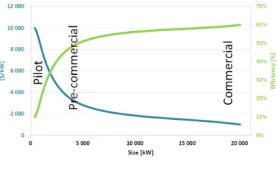
In the literature reported, most of the interest is dedicated to industrial scale LAES (with a liquid air production up to 300 tons per day) to compete with large-scale energy storage technologies such as CAES and PHE. There are mainly two reasons that have to lead the actual research on large-scale LAES. The first reason regards the application, indeed large-scale energy storages can be integrated into an energy system based on extensive centralized energy production plants. Furthermore, large scale is more suitable to be coupled with a waste heat source from industrial sites such as the LNG regasification terminals where plenty of waste cold, that could be used to produce liquid air, is available. Highview Power, for example, has been working on the development of a LAES that can deliver around 5MW/15MWh – to significantly more than 50MW/200MWh [9]. The other advantage of large-scale LAES is due to the higher round-trip efficiency and the reduction of the capital cost when the LAES is scaled-up. Figure1.6 shows that, at the actual state of research, the cost of the plant increase at small size due to the poor efficiency estimated.
However, although a large portion of the electric power produced still realize on large centralized systems, the energy system is moving towards to a decen-tralized energy production system with distributed energy resources (DER) and Microgrids. DER refer to a small source of electric power that is connected di-rectly to the power system distribution and didi-rectly consumed by the user. The
Figure 1.7.: Small-scale LAES integrated to a Microgrid
term "microgrid", proposed by the Consortium for Electric Reliability Technol-ogy Solutions, defines as multiple systems of DER, controls and final user able to enhance the local reliability and flexibility of the system[38]. The interest to move on decentralized systems is their ability to reduce the transmission cost of the electricity and allow a better integration with the energy produced from renewable sources. A microgrid system supplied with REs must guarantee the balance between the supply and the energy demand. Therefore in this con-text, energy storage is a fundamental component. The potential of the LAES technology and the related advantages make it interesting to the investigation of a small-scale (microgrid scale) that can be suitable for DER and microgrid applications as shown in Figure1.7. The novel term of microgrid scale LAES proposed in this work defines a system that integrates a liquefaction plant with a daily production ranging between few tons and few tens of tons of liquid air, that corresponds to a size of air liquefaction plant between the lab and industrial scale. The aim of this work is to start the challenge of scaling down and reduce the size of the LAES contributing to the scientific community to understand the potential of this technology and inspire future research.
When scaling down the LAES, the high specific consumption of the lique-faction cycle mainly affects the final value of the roundtrip efficiency of the system. Chapter 2 aims to investigate the liquefaction plant configuration that minimizes the specific consumption of a microgrid scale LAES. In particu-lar different liquefaction cycles, suitable for the small scale, are analyzed and compared by mean of simulation software and an optimal configuration that minimizes the specific consumption is proposed. At the end of the chapter, a novel solution to recover the waste heat of compression is proposed to re-duce the specific consumption of the microgrid LAES liquefaction plant with the integration of a LiBr-water absorption chiller. A complete configuration of microgrid LAES is presented in Chapter 3. The system has been modeled and a parametric analysis has been conducted varying the main operative parame-ters and analyzing the key performance parameparame-ters of the LAES system. The
results, that consist of a large amount of data, have been elaborated and novel performance maps are proposed. The four maps proposed, can be a useful tool to assist the design of microgrid scale LAES offering a simple graphical method to estimate the performance of the system. Chapter 4 and Chapter 5 focus on the waste cold recycle of the system, in particular on the design of the High Grade Cold Storage (HGCS). The actual solutions of HGCS are packed bed sensible heat storage characterized by a low energy density and bulky in terms of dimensions. The idea proposed in this work is to integrate into the HGCS, one or more part of phase change materials (PCMs) to increase the storage energy density and reduce the dimensions. The design of a hybrid HGCS is part of a project done in collaboration with TESLAB@NTU based in the Nanyang Technological University of Singapore consisting of different steps. In this work, the task of thermal characterization of low temperature PCM for the hybrid HGCS has been afforded. In particular, the aim was to ad-dress a methodology to measure the thermal response and predict the thermal behavior of low temperature PCM. In particular, an experimental rig has been designed to test the thermal response. The results obtained have been used to validate a 1-D numerical model that can be used to predict the thermal behavior of the PCM. Due to their well-known properties, the methodology has been first validated using pure deionized water as PCM materials. Then the methodology has been tested and further validated to on a sub-zero PCM material based on aqueous ethylene glycol solution. The last chapter of this work reports the overall conclusions and ideas that can be addressed for future works.
Chapter 2.
Preliminary study on a microgrid
scale LAES air liquefaction plant
All the literature published on LAES system highlights that the high spe-cific consumption of the liquefaction process represents the main hurdle which adversely affects the LAES round trip efficiency. Since the plant size has a significant impact on the liquefaction process, the aim of this part of the work mainly lies in the following aspects:• To analyze and compare the main cycles used for air liquefaction that can be used to a small-scale LAES
• To find an optimal configuration and operating range aiming at minimiz-ing the specific consumption
• Propose a solution to improve the efficiency of the liquefaction cycle de-creasing the specific consumption
• The liquefaction plant considered for a microgrid scale is supposed to produce 10 tons/day hypothesizing a LAES charging process of 12 hours.
2.1. Optimal configuration and operating range of
a “microgrid scale” LAES air liquefaction plant
The present study contributes to provide a preliminary analysis for the esti-mation of the specific consumption of small-scale liquefaction plants and to suggest an optimal configuration with an optimal operating range to be used as a guideline for future researches and applications of LAES in microgrid and demand side applications. The most common plants used for the air liquefac-tion are first described and then compared by means of a parametric analysis conducted by simulation by means of the software Aspen HYSYS. The com-parison is based on the evaluation of the specific consumption, the component efficiency and an exergy analysis. An additional case study for air liquefaction cycles considering a pressurized phase separator is evaluated. At the end of this section a results and comments are reported and an optimal configuration for a microgrid scale LAES liquefaction cycle is suggested.2.1.1. Introduction to the air liquefaction cycles
One of the first air liquefaction cycles was patented in 1985 by Linde and Hampson. An ideal Linde-Hampson cycle consists of an isothermal compres-sor, a heat exchanger, a Joule-Thompson (J-T) valve and a phase separator. Due to its irreversibility, the liquid yield is usually less than 10%. Variants of the Linde-Hampson consist of the precooled J-T and the dual pressure cy-cle [39]. The ideal Claude cycy-cle derives from the Linde cycy-cle and combines the isenthalpic expansion of the J-T valve and the isentropic expansion of an expander. The main variants of the Claude cycle are the Heylandt and the Kapitza cycle; the former is mainly used for high pressure liquefaction cycles whereas the latter is used for low operating pressures. Modern development of air liquefaction cycles make use of single mixed refrigerants process [11]. This process is also widely used in the natural gas industry [40] where the liquefac-tion is assisted by the vaporizaliquefac-tion of a mixture of different gases that better match the cooling profile of the natural gas. This leads to an increase in the performance of the liquefaction process but, on the other hand, its complex-ity and costs increase substantially. In the case of air liquefaction, the single mixed refrigerants process can be used in the Linde and in the Kapitza cycles to precool the air. In this chapter an analysis of the Linde-Hampson, Claude and Kapitza liquefaction cycles is conducted in order to find the configuration and the range of operating conditions that minimize the specific consumption of a small-scale air liquefaction cycle. The description of each cycle and the assumptions behind the simulations set-up are described below.
2.1.2. Materials and methods
Simulation of the processes
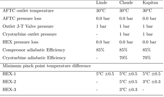
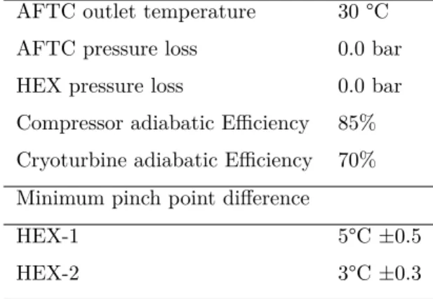
The simulation of Linde-Hampson, Claude and Kapitza liquefaction cycles were carried out using the software Aspen Hysys [41]. The boundary conditions used for the simulation of the cycles are given in Table 2.1.
Linde-Hampson process A Linde-Hampson cycle is shown in Figure 2.1 and is composed by a compressor (C-1), an aftercooler (AFTC), a heat exchanger (HEX-1), a J-T valve and a phase separator (PS). The ambient air is firstly compressed at high pressure (1-2) and then cooled down near ambient tem-perature (2-3). Then, the air passes through the heat exchanger (HEX-1) in which it is further cooled down (3-4) by the cold vapor recirculating from the phase separator (6-7). The J-T valve then completes the liquefaction process by expanding the air down to ambient pressure (4-5); this leads to a two-phase mixture which is then separated in the phase separator where the liquid air is extracted. The cold vapor (7) after passing through the heat exchanger (HEX-1) is then mixed with the ambient air at inlet of the compressor.
Figure 2.1.: Schematic of the Linde-Hampson liquefaction cycle
Claude process Unlike the Linde-Hampson cycle, the Claude cycle includes an cryoturbine (CT) and two more heat exchangers (HEX-2, HEX-3). As shown in Figure 2.2, the compression phase is the same as that of the Linde-Hampson cycle. After the high temperature heat exchanger (HEX-1) the main stream of air (4) is separated into two streams (5a) and (5b). The first stream (5a) passes through the medium temperature (HEX-2) and the low temperature heat exchanger (HEX-3) for then being expanded through the J-T valve; the resulting two-phase mixture is separated in the phase separator (PS), where the liquid air is extracted. The second stream (5b) is expanded directly through