Set Up and Preliminary
Assessment
of a 3D Numerical
Model for the Thermo-Fluid
Dynamics Analysis of an
Open Square Lattice Core of a Lead CooledReactor
Descrittori
Tipologia del documento:
Rapporto Tecnico
Collocazione contrattuale: Accordo di Programma ENEAlMSE
Argomenti trattati:
Generation IV reactors
Reatton nuclean veloci
Tennoidraulica dei reattori nucleari
Sommario
This report describes the sei up of a simplified three-dimension numerical model for the
thenno-fluid dynamic analysis of an open square lattice reactor core lead cooled on the basis of a
three-dimension CFD computer code developed by DIENCA UniBo. A preliminary assessment of the
model has been perfonned by comparing its resu1tswith the T/H reactor core behavior predicted
with a one-dimension independent channel model based on RELAP5 code. To this purpose the
conceptual design of the LFR core developed in the framework of the ELSY EU collaborative
project has been adopted as a reference. Moreover, in arder to support the set-up ofthe model, some
resu1tsofthe CFD analysis for fuel bundle ofliquid metal reactors have been considered.
Note:
Copian.
In caricoa:
2
NOME FIRMA1
NOME FIRMAO EMISSIONE 27/03/2008 NOME
M.pojjdorV2fl
P.Meloni
R.TintiFIRMA
'
Table of Contents
1.
INTRODUCTION ... 3
2.
SET-UP OF THE 3D MODEL FOR A LEAD COOLED REACTOR CORE... 4
2.1 ELSY CORE GEOMETRY ... 4
2.2 CORE POWER DISTRIBUTION ... 7
2.3 PRESSURE DROPS DISTRIBUTION ... 8
3.
ASSESSMENT OF THE 3D MODEL AGAINST A ONE-DIMENSION
INDEPENDENT CHANNEL ANALYSIS... 10
3.1 RELAP5 CORE MODEL... 10
3.2 3D AND 1D RESULTS COMPARISON ... 12
4.
EVALUATION OF MAIN 3D EFFECTS ON CORE T/H SIMULATION... 14
4.1 EVALUATION OF TURBULENT VISCOSITY EFFECTS... 14
4.2 EVALUATIONS OF PLENUM DISTRIBUTION PRESSURE EFFECTS... 16
5. CONCLUSIONS... 19
6. REFERENCES ... 19
APPENDIX A – CFD PROGRAM AND INPUT ... 21
1. Introduction
Within the framework of national AdP ENEA-MSE and international R&D programs ELSY
collaborative project [1] several innovative solutions for a liquid metal fast reactor design are
being investigated. Among these solutions the open-assembly core option adopted by ENEA
for the preliminary neutronic analysis of the ELSY reactors requires a new approach to the
thermal-hydraulic core design respect to the previous already well-established design of
Liquid Metal Reactor [2]. Therefore ENEA have planned to follow a two-step approach at the
T/H analysis of the core:
•
utilization of a one-dimensional RELAP5 model for independent channels analysis for a
prompt verification of the thermal-hydraulic and safety of the core neutronic design.
•
development of a dedicated tool for the evaluation of the intermingled effects between
assembly flows.
While the preliminary evaluation with RELAP are already in progress within the frame of the
European Project, the development of a full 3D CFD code with the purpose of analyzing the
whole core behavior has been undertaken within the frame of the AdP ENEA-MSE.
To this purpose the DIENCA department of the University of Bologna has determined and
implemented a suitable resolution scheme of full three-dimensional incompressible
Navier-Stokes and energy equations. The numerical simulations take place at a coarse, assembly
length level and are linked to the fine, sub-channel level state through transfer operators based
on parametric coefficients that summarize local fluctuations. The overall effects between
assembly flows are evaluated by using average assembly turbulent viscosity and energy
exchange coefficients. For an exhaustive description of the physical-mathematical CFD
program employed, see reference [3].
ENEA has performed a preliminary assessment comparing the 3D results obtained for a
characteristic lead cooled open core with the results obtained with the RELAP5
one-dimensional independent channels approach. Moreover, a first estimation of the average
assembly turbulent viscosity and energy exchange coefficients have been carried out on the
basis of pre-existing CFD simulations over limited subassembly regions. Finally, the pressure
distribution in the upper and lower plenum has been considered as boundary conditions for
the 3D model of the open core, in order to obtain a first evaluation of the effect of the flow
patterns in the plena on the intermingled effects between assembly flows.
2. Set-up of the 3D model for a Lead Cooled Reactor Core
Reminding to the reference [3] for detailed information about the numerical algorithm, it is
recalled here the main characteristic of the full 3D code. The purpose of this code is to
investigate three-dimensional pressure, velocity and temperature fields inside nuclear reactors
at the coarse fuel assembly level when all the sub-channel details are summarized in
parametric coefficients.
The model of the ELSY core have been set up in order to be benchmarked with a RELAP5
model with separated channels. To this purpose some simplifying assumptions have been
introduced:
• any core assembly is considered an homogeneous and continuous lattice of fuel pins;
• the radial exchange of momentum and energy is modeled with empirical coefficients [4];
• turbulence effects are modeled with a simple LES approach;
• pressure losses are modeled by using standard mono-dimensional correlations;
• the dummy/reflector region and control rod assemblies are not simulated.
The three-dimensional code solves the Navier-Stokes equations coupled with the
incompressibility constraint and the energy equation in the reactor domain where lamped
coefficients are use to model the sub-grid structures and forces. The values of these
coefficients are still an open question and standard generic correlations are used in this
computation for momentum and energy exchange coefficients [5-6].
2.1 ELSY Core Geometry
In the framework of the studies for the next generation of nuclear power plant well-known as
GEN-IV [7], the ELSY (European Lead cooled System) project of the VI European
Framework Program is addressed at the development of an European LFR (Lead Fast
Reactor) design. It aims at investigating the technical/economical feasibility of a high power
critical fast reactor with waste transmutation capability responding to the requirements of
sustainability, non-proliferation and energy production at lower costs.
Such an innovative project needs the investigation of different design solutions that concern
the overall power plant. The present study focuses the attention on the open square fuel
assembly (FA) option. The advantages to consider FAs without wrapper are quite evident e.g.
the in-vessel structures weight are reduced, there are lesser absorber materials in the active
core region, an increased power density, lesser risks of FA blockage, the reduction of the
hot-spot temperatures, etc.
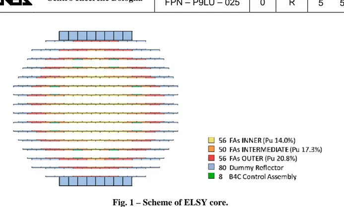
The ELSY reactor core consists of an array of 162 FAs wrapperless [8] with three different
fuel enrichment in plutonium and 80 surrounding dummy/reflector assemblies. The reactor is
controlled by 8 scram control rods plus 70 finger absorbers sparse in the core for scram and
regulation. In Fig. 1, it is shown a schematic view of ELSY core.
Fig. 1 – Scheme of ELSY core.
The structure of the fuel assembly is characterized by a square lattice of 21 by 21 fuel pins of
which the four angular ones are replaced with stainless steel structure for mechanical reason.
It is peculiar the presence of a structural void square tube located in the assembly centerline to
host the finger absorber replacing 3 by 3 pins. The fuel pins are supported along their lengths
with five spacer grids to maintain the distances among them. The fuel adopted is a MOX with
three different plutonium enrichment (radially increase) and the clad is the ferritic-martensitic
stainless steel T91. In particular, the fuel is hollowed to increase the volume for the gaseous
fission products, solution that allow to reach a burnup up to 100 MWd/kg of heavy metal. Fig.
2 shows the fuel assembly and fuel pin design and dimensions.
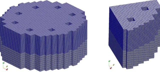
The model meshing and its x, y, z view are shown in Fig. 3. Each assembly is represented by
4×4×20 Hex27 finite elements. For the quarter reactor the number of nodes are 116481, the
dofs 481485 (velocity, pressure and temperature) and the elements are 15561. In this case the
domain is discretized by standard Lagrangian finite element families which satisfy the
standard approximation properties. In order to solve the pressure, velocity and energy field it
is used the finite space of linear polynomials for pressure and the finite space of quadratic
polynomials for velocity and energy.
Fig. 3 – Full reactor and computational domain
The fuel assembly dimension is extended up to 29.4cm due to thermal expansion at working
condition temperature 400°C. Axially the computational description considers a region which
is 0.9m below and 0.2m above the core for a total of 2m. The heat generation zone or the
active core zone for the reactor starts at H
in= 0.9m and ends at H
out= 1.8m. Due to the fact
that the model describes the reactor at assembly level, the sub-assembly composition is seen
as an homogeneous medium. Data about this composition can be found in Tab. 1.
area
(m
2)
Pin area
Corner box area
Central box beam
Channel central box beam area
Coolant area
Assembly area
Coolant/Assembly ratio
370.606 × 10⁻⁴
5.717 × 10⁻⁴
2.092 × 10⁻⁴
12.340 × 10⁻⁴
473.605 × 10⁻⁴
864.360 × 10⁻⁴
0.548
2.2 Core Power Distribution
The power generated by ELSY reactor is 1500MWth. At the beginning of cycle (BOC)
conditions considered for the present work, the power can be split among the fuel regions
inner, intermediate and outer respectively in about 501, 489 and 492MWth. Part of the total
power, about 18MWth, is deposited in the dummy/reflector region and in structural materials
above and below the active core region. This power is not taken into account in the models.
In Fig. 4 it is shown the scheme and labeling of the quarter reactor computed, scheme that will
be used to compare the results between CFD and RELAP5. The relative table shows the
power produced in each fuel assembly.
TABLE OF POWER [MW]
INNER INTERMEDIATE OUTER
A11/2* 8.606 A16/2* 10.775 A17/2* 10.036 A12/2* 8.801 A2_5 10.188 A2_7 10.908 A13/2* 9.043 A2_6 10.269 A2_8 7.842 A14/2* 9.301 A3_4 9.943 A3_7 8.465 A15/2* 9.560 A3_6 9.249 A4_7 8.520 A21/2* 8.678 A4_5 10.132 A5_5 10.962 A2_2 8.759 A4_6 9.399 A5_6 8.621 A2_3 8.943 A5_2 9.696 A6_5 9.766 A2_4 9.112 A5_3 9.857 A6_6 7.776 A3_1 8.811 A5_4 10.400 A7_2 9.746 A3_2 8.921 A6_2 9.410 A7_3 8.833 A3_3 9.071 A6_4 9.057 A7_4 7.699 A41/2* 8.850 A7_1 9.318 A81/2* 8.029
A4_2 8.903 A8_2 7.806
A4_3 9.043 A8_3 6.922
A4_4 9.218
A5_1 8.790
A61/2* 8.725
(*) Power referred to the entire fuel assembly
Fig. 4 – Scheme and labeling of reactor modeled and power generated in each FA
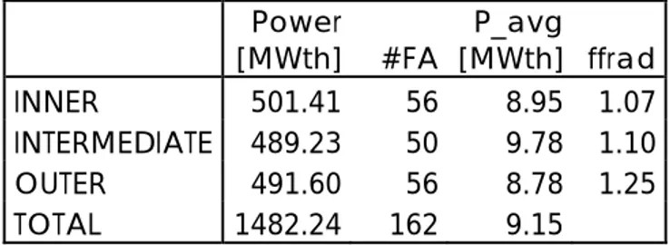
The subsequent Tab. 2 summarize the power produced by ELSY and put in evidence the
average power and the correspondent radial form factor referred to each fuel zone which is
defined as the ratio of maximum power and average power.
Power [MWth] #FA P_avg [MWth] ffrad INNER 501.41 56 8.95 1.07 INTERMEDIATE 489.23 50 9.78 1.10 OUTER 491.60 56 8.78 1.25 TOTAL 1482.24 162 9.15
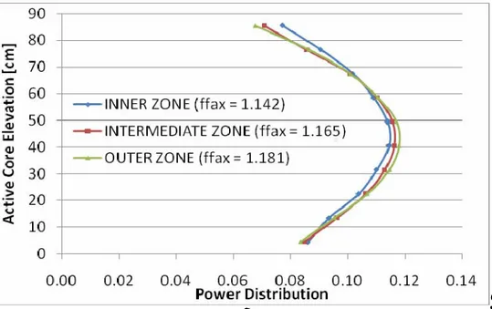
The axial power distributions adopted for the different fuel zones are shown in Fig. 5 with the
correspondent axial form factor.
Fig. 5 – Axial Power Distributions and Form Factor
For the given power of 1482.2MWth and the lead heat-up over the core of 80°C (mixing
temperature), the lead mass flowrate is fixed to a value of 124540 kg/s.
2.3 Pressure Drops Distribution
The distributed friction losses are calculated with the Coolebrook-White correlation imposing
a walls roughness of 3.0e-6m. The concentrated pressure drops, limiting the attention at the
core region, are due to the abrupt area change at core inlet, to the presence of five spacer grids
with a relative plugging of 0.33 and finally to the area change at core outlet.
The grid spacers pressure drop are evaluated using Rehme approach [10], considering a lead
velocity of 1.6m/s (obtained fixing the flow area and the mass flowrate) and the relative
plugging. The relative pressure drop calculated results of about 7000Pa each grid that
correspond to a factor k=0.52. Contraction and expansion pressure drops at core inlet and
outlet are taken into account by means of concentrated coefficients k=0.5 at core inlet and
k=1.0 at outlet. The Tab. 3 summarizes the concentrated pressure drops assumed.
k factor
Core Inlet 0.50
Spacer Grid (5) 0.52
Core Outlet 1.00
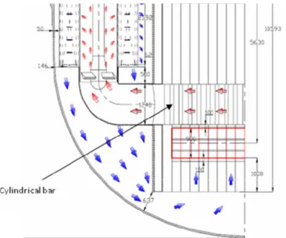
There is another concentrated pressure drop that could have an important effect on the core
thermal-hydraulics due to the presence of cylindrical support structures of finger absorbers.
Their presence causes an additional pressure drop along the path from the FA nozzle outlet to
the pumps inlet that decrease radially, see Fig. 6.
Fig. 6 – Sketch of the lead flow motion in ELSY
This pressure drop have a fall back in the fluid dynamic behavior of the whole core, this is
true in particular for the open square fuel assembly because it creates a radial pressure
distribution at the core outlet with effects on the flow patterns among the assemblies. It is
expected an increase of the radial flow component through the assemblies with a more
uniform outlet mixing temperature. The relative pressure distribution at the core outlet,
evaluated with correlation in literature [11], has been assumed as a boundary condition to take
into account this effect. Fig. 7 shows the radial distribution of this additional pressure drop .
3. Assessment of the 3D model against a one-dimension independent
channel analysis
IN a first phase the thermal-hydraulic code RELAP5, modified to treat heavy liquid metal
[12], has been used to have a conservative evaluation on the system/core behavior at nominal
and accidental conditions and for safety purpose. Although the limits of RELAP5 bring to
have an approach remarkably conservative in the simulation of the open core thermo-fluid
dynamics, in this work it is adopted to assess the dedicated full 3D CFD code previously
described that allows taking into account the intermingled effects among assembly flows
3.1 RELAP5 Core Model
The results of the core simulation obtained with the model described in the previous chapter
will be compared against the results obtained with a model developed for RELAP5 code [13]
to verify and appreciate the effects of the “open” square lattice reactor e.g. cross flow and
thermal exchange through the assemblies.
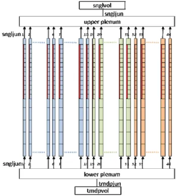
The model developed for RELAP5 code is based on the idea to simulate each FA with an
independent channel, taking advantage of core symmetry the description is limited to a
quarter reactor as shown in Fig.4. The dummy reflector and control rod assemblies are not
taken into account, this means that the separate channel model of the reactor consist of 46
parallel channel (18 FA inner, 13 FA intermediate and 15 FA outer) each one connected with
an upper and lower junction to the volumes that represent the plenum as shown in Fig. 8.
The half sub-assemblies placed on the edge of modeled region are simulated with half flow
area and relative half power. The boundary conditions imposed are:
• core inlet temperature of 400°C in the lower plenum
• core mass flowrate at the inlet time-dependent junction of 124540 kg/s to have a mixing
outlet temperature of 480°C at a given thermal power produced (1482.2MWth)
Each pipe/FA of Fig. 8 is divided in 16 axial meshes and a fuel pin thermal structure is
associated at the active core height starting from 0.9m up to 1.8m along 10 axial meshes
useful to define the axial power distribution.
The distributed pressure drops are computed directly by the code the Zigrang-Sylvester
engineering approximation to the Coolebrook-White correlation and the concentrated pressure
drops at inlet, outlet and five spacers grids are introduced as a k factor as described in §2.3.
The heat transfer correlation implemented is the Zhukov correlation without spacers as
suggested for square lattice pins by the ELSY technical group [14].
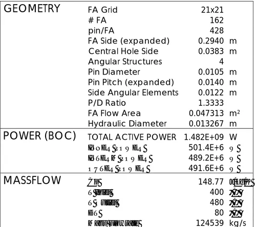
The main thermal-hydraulic parameters used to assess the model and referred to the whole
reactor core are reported in the Tab. 4.
GEOMETRY
FA Grid 21x21# FA 162
pin/FA 428
FA Side (expanded) 0.2940 m
Central Hole Side 0.0383 m
Angular Structures 4
Pin Diameter 0.0105 m
Pin Pitch (expanded) 0.0140 m
Side Angular Elements 0.0122 m
P/D Ratio 1.3333
FA Flow Area 0.047313 m2
Hydraulic Diameter 0.013267 m
POWER (BOC)
TOTAL ACTIVE POWER 1.482E+09 WINNER POWER 501.4E+6 W
INTERM POWER 489.2E+6 W
OUTER POWER 491.6E+6 W
MASSFLOW
Cp 148.77 J/kg/KT Inlet 400 °C
T Outlet 480 °C
DT 80 °C
Mass Flowrate 124539 kg/s
3.2 3D and 1D Results comparison
As a first assessment of the 3D core model, it has been carried out a benchmark case where
the results are expected to be very similar to those of RELAP5 independent channel model. In
particular, the 3D simulation of the open core has been carried out without taking into account
the turbulent viscosity and with constant pressure boundary conditions both at core inlet and
outlet. In this configuration the model provides almost the one-dimensional solution, since the
effect of momentum and energy exchange among assemblies is widely negligible. To put in
direct comparison the results obtained with the two codes, in the 3D model are considered the
value referred only to the central nodes of each subassembly.
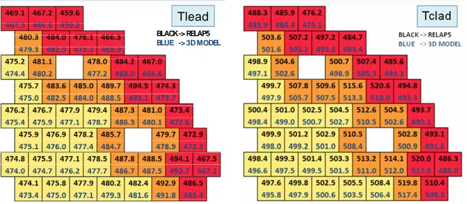
The Fig. 9 shows the comparison between the core outlet lead temperatures. It is possible to
see that starting from the same thermal-hydraulic conditions e.g. pressure drop 0.92 bar, lead
velocity 1.598 m/s, power produced 1482 MWth, etc., the temperatures calculated by
RELAP5 are slightly higher of those obtained with the 3D model. The difference range from
0.2 to 1.9 degree and as a consequence of this the average temperature drop over the core
calculated with the two models differs of about one degree. The discrepancy could be
explained by a slight difference in lead density. In fact, the density calculated by RELA5
respect the 3D model results underestimated of 130kg/m
3that corresponds to about 1% error
in mass flowrate, hence in the ΔT over the core.
BLACK-> RELAP5
BLUE -> 3D MODEL
The tridimensional code is able to investigate the pressure, velocity and temperature fields but
since the model describes the reactor at assembly level, the sub-assembly composition is seen
as an homogeneous medium. Hence, it is not provided of a pin thermal structure like
RELAP5. In order to derive the temperature cladding field from the bulk lead temperature and
power distribution the following formula has been implemented in the 3D model:
where Q is the volumetric heat generation and h is the heat transfer coefficient that could be
determined by the definition of Nusselt number, Nu=hD/k, where D is the characteristic
dimension of the system and k is the thermal conductivity. Also in this case the Zhukov heat
transfer correlation [15] has been taken as a reference for the evaluation of heat transfer
coefficient h.
The comparison of the clad temperatures, shown in Fig. 10, underlined the good agreement
between the methods, the slight discrepancies of the order of two degrees are consequence of
the discrepancies already mentioned in the lead temperatures.
.
BLACK-> RELAP5
BLUE -> 3D MODEL
4. Evaluation of main 3D effects on core T/H simulation
The benchmark test described in previous chapter has aimed at verifying the coherence of the
results obtained with the new tridimensional model and a well known thermal-hydraulic tool
as RELAP5. To do this some simplifying options have been considered e.g. constant pressure
at inlet and outlet, losing almost completely the characteristic tridimensional effects of the
unwrapped option.
This chapter analyze the effect on the 3D simulation to introduce a simple LES turbulent
model to consider the turbulent viscosity effect and then, to impose a non-uniform pressure
boundary condition at core outlet. In this way, the capability of the 3D model developed to
simulate a fully tridimensional behavior of the open core will be preliminary assessed.
4.1 Evaluation of turbulent viscosity effects
In a reactor like ELSY, the effect of the turbulence viscosity could be very important. In fact,
due to the relative high velocities of the lead that pass through the core, the heat conduction in
liquid metal still have an important role but the convection is the dominant heat transfer
mechanism. Follow that the distribution of temperatures could be accurately predicted by
using one-dimensional models along the convective streamlines. For this reason we should
expect good agreement between the RELAP5 and the three-dimensional computations for
highly forced flows but poor matching for flows where the main heat transfer mechanism is
not convection.
A first evaluation of the turbulence energy exchange term, required by the LES model, has
been based on some CFD simulation over limited subassembly regions [17, 18]. The
introduction of a simple LES turbulence model has produced results that can be seen in Fig.
11 in comparison of those obtained in the previous RELAP5 calculation.
BLACK-> RELAP5 BLUE -> 3D MODEL
Tlead
To improve the readability of the results, in Fig. 12 it is shown the comparison between core
temperatures computed by the CFD model with and without LES model.
NO TURBOLENCE
LES TURBOLENT MODEL
a) Tridimensional view of relative temperature
b) Top view of relative temperature
Fig. 12 – Temperature comparison with and without LES turbulence model.
With the introduction of the standard LES model, the temperature profile becomes smoother,
thus reflecting the interaction between the fuel assemblies. Starting from the same boundary
condition of uniform pressure at core inlet/outlet and temperature at inlet, the fluid motion
remain mainly vertical and the velocity uniform in magnitude, however, as can be seen in the
Fig. 12a, the maximum temperature computed is three degree lower compared to the case
without LES. This is a not negligible result because the difference could increase in particular
accident scenarios thus involving the safety aspects, first of all the reduction of the hotspot
temperatures.
However these results must be considered only preliminary results since for a very accurate
evaluation of the turbulence energy exchange term a sub-channel analysis is needed in order
to introduce the correct parameters that define this behavior [16].
4.2 Evaluations of plenum distribution pressure effects
A radial differential pressure distribution has been introduced at the core outlet as a boundary
conditions to simulate the influence of the global ELSY cooling system on the core behavior.
As already mentioned in paragraph 2.3, the presence of cylindrical support structures of finger
absorbers in the upper plenum introduce a differential pressure drop at core outlet, higher in
the center lower in the core periphery, with consequence in whole reactor behavior, which
could be of particular importance in case of open assembly.
In this case, where the outlet profile of pressure is not uniform and in addition the 3D power
distribution is considered, the computation become fully three-dimensional. A parabolic
axisymmetric profile of the outlet pressure distribution is imposed (see Fig. 7) both in 3D
model and RELAP5 calculations. In case of the tridimensional simulation the velocity field
changes direction and magnitude inside the core and the outflow temperature profile differs
substantially from the RELAP5 model, as shown in Fig. 13.
In this figure one can see that the temperatures computed with the three-dimensional code are
slightly lower in the inner zone and higher in the outer zone to those computed by using the
RELAP5 model. In the Fig. 14a it can be seen that temperatures computed with the
tridimensional code are consistently lower (eleven degree) in comparison of which obtained
setting the constant outlet pressure.
BLACK-> RELAP5 BLUE -> 3D MODEL
Tlead
BLACK-> RELAP5 BLUE -> 3D MODELTclad
Fig. 13 – Effect of outlet pressure distribution
This result does not show the relevant conservative character of the RELAP5 model and it has
to be red considering the particular scenario simulated. The 3D power distribution described
in the test is related to ELSY BOC conditions and is not representative of the situation during
the most part of the reactor operation. In fact, in order to flatten as much as possible the power
distribution during the entire fuel cycle, at BOC a relative higher power is produced in the
outer region respect in the inner one. During the burnup process the performance of this
region become worse in favor of the innermost regions. Therefore, at BOC conditions to
consider the pressure distribution at core outlet limit the maximum temperatures which is
located in the outermost fuel assemblies. Since at EOC conditions there is a consistent change
in power distribution among the fuel regions, which increases in the inner and intermediate
zones and decreases in the outer one, the fuel temperatures already higher in the inner region
are subjected to further increase in case of an independent channel simulation performed with
RELAP5. This behavior highlights the character too conservative of the RELAP5 simulation
that is not suitable to smooth the lead temperature at the core outlet as calculated by the
tridimensional model.
The Fig. 14b shows the magnitude of the velocity field, higher in the outermost region with a
foreseeable minimum value in correspondence of the core Z axis. The Figs. 14c and 14d show
the magnitude of X and Y axis velocity component. The subsequent Fig. 15 collects the
temperature, velocity and pressure fields at core inlet (on the left) and core outlet (on the
right).
These results are a clear example of how a fully three-dimensional thermal-hydraulic
simulation of the ELSY open core could avoid unnecessary conservative approach in the
design assessment and safety analysis that could have a negative impact on the economic
feasibility of the reactor.
a) Relative Temperature
b) Velocity Magnitude
c) Velocity along X axis
d) Velocity along Y axis
CORE INLET
CORE OUTLET
a) Relative temperature (400°C)
b) Relative temperature (400°C)
c) Velocity
d) Velocity
e) Relative Pressure (bar)
f) Relative Pressure (bar)
5. Conclusions
Within the framework of the national AdP ENEA-MSE a simplified three-dimension
numerical model of an open square lattice reactor core has been developed with the purpose to
take into account the intermingled effects between assembly flows, thus limiting the
conservative approach of the analysis in support to core design and safety study.
A preliminary assessment of the model has been performed by comparing its results with the
T/H reactor core behavior predicted with a one-dimension independent channel model based
on RELAP5 code. To this purpose the conceptual design of the LFR core developed in the
framework of the ELSY EU collaborative project has been adopted as a reference.
This preliminary assessment comparing the 3D results obtained for a configuration where the
model is expected to provide almost the one-dimensional solution, with the results obtained
with the RELAP5 one-dimensional independent channels approach has been satisfactory. In
fact, the slight differences between the lead temperatures calculated by two models are
justified by sleight differences in the lead physical property used.
In spite of the preliminary character of the results obtained with the 3D model, which still
needs additional and relevant efforts for an accurate evaluation of the turbulence energy
exchange term, the results obtained introducing a simple LES turbulence model and a
pressure radial distribution outlet profile have been discussed against the results obtained with
the RELAP5 separated channel model. These further tests have showed as a fully
three-dimensional thermal-hydraulic simulation of the ELSY open core could avoid unnecessary
conservative approach in the design assessment and safety analysis that could have a negative
impact on the economic feasibility of the reactor.
6. References
[1]. ELSY Work Program, “European Lead-cooled SYstem (ELSY) Project”, Technical
report, EURATOM, Management of Radioactive Waste (2006).
[2]. L. Cinotti et al., “The potential of the LFR and the ELSY Project”, Proc. of 2007
International Congress on Advances in Nuclear Power Plants (ICAPP ’07), Nice,
France, May 13-18, 2007 (2007).
[3]. A. Cervone and S. Manservisi, “A Three-Dimensional CFD Program for the Simulation
of the Thermal-Hydraulic Behavior of an Open Core Liquid Metal Reactor”, Technical
Report LIN-THRG 108, XUNIBO-P9LU-001, December 2008.
[4]. Kirillov, P.L., Ushakov, P.A., 2001. "Heat transfer to liquid metals: specific features,
methods of investigation, and main relationships," Thermal Eng., 48(1), pp. 50–59
(1993).
[5]. P. L. Kirillov, "Experience in operating reactors indicates the need for new
thermohydraulic studies," At. Tekh. Rubezh., 9, pp.3–9 (2003).
[6]. Yu. V. Yudov, S. N. Volkova, and Yu. A. Migrov, "Closure relations for
thermohydraulic model of the KORSAR computer code," Teploénergetika, 11, pp. 22–
29 (2002).
[7]. U.S. DOE Nuclear Energy Research Advisory Committee and the Generation IV
International Forum, “A Technology Roadmap for Generation IV Nuclear Energy
Systems”, Technical Report GIF-002-00 (2002).
[8]. C. Artioli, G. Grasso, M. Sarotto and J. Krepel, “ELSY Neutronic Analysis by
deterministic and Monte Carlo methods: an innovative concept for the control rod
systems,” Proc. of 2009 International Congress on Advances in Nuclear Power Plants
(ICAPP ’09), Tokyo, Japan, May 10-14, 2009 (2009).
[9]. I.E. Idelchik, Handbook of Hydraulic Resistance, 3
rdEdition, Published by Jaico
Publishing House, (2000).
[10]. Klaus Rheme, “Pressure drop correlations for fuel element spacers,” Nuclear
Technology Review, 17, (1973).
[11]. I.E. Idelchik, Handbook of Hydraulic Resistance, 3
rdEdition, Published by Jaico
Publishing House, (2000).
[12]. P. Meloni, et al., “Investigation of RELAP5 Capability to simulate the LBE Cooling
System Thermal-Hydraulic,” Proc. of the 8
thInformation Exchange Meeting on
Transmutation and Partitioning (IEMTP08), Las Vegas, USA, November 9-11, 2004
(2005).
[13]. S. M. Sloan, R. R. Schultz, and G. E. Wilson, RELAP5/MOD3 code manual, Tech. Rep.
NUREG/CR-5535, INEL-95/0174, Nuclear Regulatory Commission, Washington, DC,
USA (1995).
[14]. K. Mikityuk, “Heat transfer to liquid metal: Review of data and correlations for tube
bundles”, Nuclear Engineering and Design, Vol. 239, Issue 4, pp. 680- 687, April 2009.
[15]. A. V. Zhukov, A. P. Sorokin, V: P. Smirnov and M. V. Papandin “Heat transfer in
lead-cooled fast reactor (LCFR),“ Proceedings of ARS’94 International Topical Meeting on
Advanced Reactors Safety, Pittsburg, USA, April 17–21, 1994, vol. 1, pp. 66-69 (1994)
[16]. E. Baglietto, H. Ninokata, Takeharu Misawa, "CFD and DNS methodologies
development for fuel bundle simulations," Nuclear Engineering and Design, 236 pp.
1503–1510 (2006).
[17]. W. Ambrosini, N. Forgione, F. Oriolo, D. Rosa, M. B. Sharabi, “CFD Analysis for Fuel
Bundles in Reactors Cooled by Liquid Metals”, CIRTEN CERSE-UniPi RL-1072/2008,
December 2008.
[18]. M. Marchetti, “Analisi CFD del Comportamento Termoidraulico del Nocciolo per il
Reattore Raffreddato a Piombo ELSY”, Thesis of Engineering Faculty in Bologna, A.A
2006/2007.
Appendix A
CFD Program and Input
The appendix would present a brief description of the CFD code structure and a sample layout
of the input files. To have a complete description of the physical/mathematical aspects
involved and computational approach, see reference [3].
A.1 Generalities
The code is written in C++ and it is constituted by a main file (ex13.C) which calls all the
necessary functions organized in five C++ classes. The five classes are:
• the class MGCase, defines input and output data flow;
• the class MGGauss, defines Gaussian integration;
• the class MGMesh, defines the geometrical mesh;
• the class MGSol, defines the Navier-Stokes equation solver;
• the class MGSolT, defines the energy equation solver.
A.2 The main file ex13.C
This file is the main program. It allocates all the needed classes and manages input and output
flow. Each time step is solved inside the temporal loop. All the settings must be specified in
the config.h file.
// C++ include files that we need #include <iostream> #include <algorithm> #include <math.h> #include <fstream> #include <map> #include "config/config.h" // --- #ifdef LIBMESHF #include "libmesh.h" #include "perf_log.h"
#define Perf_logstart_event perf_log.start_event #define Perf_logstop_event perf_log.stop_event #else
#define Perf_logstart_event (printf) #define Perf_logstop_event (printf) #endif // --- #include <lastypes.h> #include "MGSolver.h" #include "MGSolverT.h" #include "MGSolverSA.h" #include "MGSolverCC.h"
#include "MGMesh.h" #include "MGGauss.h" #include "MGCase.h" #include "config/data.h"
// *********************************************************** // The main program.
// **********************************************************CODE DOCUMENTATION 65 int main(int argc, char** argv) {
#ifdef LIBMESHF // Initialize libMesh. libMesh::init(argc, argv); { // --- PerfLog perf_log("NSE"); #endif #ifdef GENCASE // ************************************** // Case Generation // ************************************* #ifndef RESTART Perf_logstart_event("GenCase"); GenCase(); Perf_logstop_event("GenCase"); #endif #endif // *************************************** // MGSolver begin
fprintf(stderr,"\n Start MGSolver \n"); Perf_logstart_event("Reading");
// Reading ******************************* // Data ---
printf(" Reading I Data:: \n"); // double dt = ND_TIME_STEP; unsigned int t_in=0;
double time=0.;
printf("\n Nondimensional Numbers: \n"); printf(" Re = %e We = %e Fr = %e \n", RHOref*Uref*Lref/MU0, RHOref*Uref*Uref*Lref/(SIGMA+1.e-6), Uref*Uref/(9.81*Lref)); printf(" Pe = %e \n",(RHOref*CP0*Lref*Uref)/KAPPA0); fprintf(stderr," - \n *\n"); // velocity fem --- unsigned int kng[3],kfem[3]; // N of gaussian points in 1D,2D,3D kng[0]=3;kng[1]=9;kng[2]=27; // Fem element type in 1D,2D,3D kfem[0]=3;kfem[1]=9;kfem[2]=27; // pressure fem --- unsigned int kng1[3],kfem1[3]; // N of gaussian points in 1D,2D,3D kng1[0]=3;kng1[1]=9;kng1[2]=27; // Fem element type in 1D,2D,3D kfem1[0]=2;kfem1[1]=4;kfem1[2]=8; // Gauss Reading --- fprintf(stderr," Reading II Gauss:: \n");
MGGauss *dgauss; dgauss=new MGGauss(kng,kfem);CODE DOCUMENTATION 66 dgauss->init(27);// hex27
MGGauss *dgauss_p; dgauss_p=new MGGauss(kng1,kfem1); dgauss_p->init(8);// hex8
printf(" - \n * \n"); //Mesh ---
fprintf(stderr,"\n Reading III Geometry:: \n"); fprintf(stderr," Mesh:");
MGMesh *mgmesh1; mgmesh1=new MGMesh(DIMENSION,gridn+1); mgmesh1->init(FILE_MESH_CASE);
printf(" - \n"); // Multigrid --- MGSol *mgs=NULL; #ifdef NS_EQUATIONS
printf("\n Reading IV Navier-Stokes Operators:: \n"); printf(" Multigrid, Matrix, Prol and Restr: \n"); mgs=new MGSol(*mgmesh1,NoLevels); mgs->MGReadOp(); printf(" - \n * \n"); #endif MGSolSA *mgsSA=NULL; #ifdef TURBULENCE
printf("\n Reading Turbulence Operators:: \n"); // Multigrid ---
printf(" Multigrid, Matrix, Prol and Restr: \n"); mgsSA=new MGSolSA(NoLevels); mgsSA->MGReadOp(*mgmesh1,0); mgsSA->InitVel(*mgmesh1,*mgs,dt); printf(" - \n *\n"); #endif MGSolT *mgsT=NULL; #ifdef T_EQUATIONS
printf("\n Reading V Energy Operators:: \n"); // Multigrid ---
printf(" Multigrid, Matrix, Prol and Restr: \n"); mgsT=new MGSolT(*mgmesh1,NoLevels); mgsT->MGReadOp();
printf(" - \n * \n"); #endif
// ************************************* // Set up time cycle t=0 *************** MGSolCC *mgcc=NULL; #ifdef NS_EQUATIONS fprintf(stderr,"\n NS Initializing:: \n"); fprintf(stderr," Solution: "); mgs->GenSol(NoLevels-1); mgs->GenOldSol(NoLevels-1);CODE DOCUMENTATION 67 fprintf(stderr," -\n"); fprintf(stderr," Rhs: "); fprintf(stderr," -\n"); #endif #ifdef TURBULENCE
fprintf(stderr,"\n Turbulence Initilize:: "); fprintf(stderr,"\n Solution: "); mgsSA->GenSol(*mgmesh1,NoLevels-1); mgsSA->GenOldSol(NoLevels-1); fprintf(stderr," - \n"); fprintf(stderr," rhs: "); mgsSA->GenRhs(*dgauss,*mgmesh1,NoLevels-1); fprintf(stderr," - \n");
#endif
#ifdef T_EQUATIONS printf("\n Energy Initilize:: "); printf("\n Solution: "); mgsT->GenSol(NoLevels-1); mgsT->GenOldSol(NoLevels-1); printf(" - \n");
#endif
printf("\n Case Initilize:: ");
MGCase *mcase=new MGCase(*mgmesh1,NoLevels,N_TIME_STEPS); mcase->init_data();
#ifdef RESTART
printf("\n Restart %d %g",RESTART,RESTARTIME);
mcase->read(*mgmesh1,*mgs,*mgcc,*mgsT,*mgsSA,RESTART,NoLevels-1); t_in=RESTART; time +=RESTARTIME; #endif mcase->print(*mgmesh1,*mgs,*mgcc,*mgsT,*mgsSA,t_in,NoLevels-1); mcase->print_bc(*mgmesh1,*mgs,*mgcc,*mgsT,*mgsSA,t_in,NoLevels-1); printf(" - \n"); Perf_logstop_event("Reading"); // --- // time loop // ---
for (unsigned int t_step=t_in; t_step< N_TIME_STEPS+t_in; ++t_step) { // Let the system of equations know the current time.
std::cout << "\n\n*** Solving time step " << t_step+1
<< ", time = " << time+ ND_TIME_STEP << " ***" << std::endl; // ---
Perf_logstart_event("MG Solver"); #ifdef NS_EQUATIONS
// solving V-cyle Multigrid
printf("\n Navier-Stokes solution:: \n");
mgs->MGTimeStep(*mcase,*mgsT,*mgcc,*dgauss,*dgauss_p,time,t_step-t_in); #endif
#ifdef TURBULENCECODE DOCUMENTATION 68
std::cout << std::endl << "\n Turbulence solution \n" << std::endl; mgsSA->MGTimeStep(*mgmesh1,*dgauss,0);
#endif
#ifdef T_EQUATIONS
std::cout << std::endl << "\n Energy Solution \n" << std::endl; mgsT->MGTimeStep(time,*mcase,*mgcc,*mgs,*dgauss,0); #endif Perf_logstop_event("MG Solver"); // --- // print Perf_logstart_event("output"); if ((t_step+1-t_in)%PRINT_STEP == 0) mcase->print(*mgmesh1,*mgs,*mgcc,*mgsT,*mgsSA,t_step+1,NoLevels-1); Perf_logstop_event("output"); time += ND_TIME_STEP; } // end time loop
// clean --- if (mcase != NULL) delete mcase; if (mgcc != NULL) delete mgcc; if (mgsT != NULL) delete mgsT; if (mgs != NULL) delete mgs; if (mgsSA != NULL) delete mgsSA;
if (mgmesh1 != NULL) delete mgmesh1; if (dgauss != NULL) delete dgauss; if (dgauss_p != NULL) delete dgauss_p; #ifdef LIBMESHF
}
return libMesh::close(); #endif
}
A.3 Configuration file config.h
The options that could be setup by user are reported in Tab.A1. The configuration file config.h
is reported below.
Tab. A1 – Options available in config.h file
#ifndef _config_cfg #define _config_cfg
// *************************************************** // BASIC SETTINGS (DIM and Navier-Stokes+Energy
// *************************************************** // space 2D or 3D ***************************
// DIM2= two-dimensional simulation (undef 3D) //#define DIM2 1
// generate the boundary mesh #define BOUNDARY 1 // 2d axisymmetric case //#define AXISYMX 1 // equation ****************************** // for NS simulations #define NS_EQUATIONS 1 //#define TURBULENCE 1 // --- // for Energy simulations #define T_EQUATIONS 1 // --- //equation TWO_PHASE
//#define TWO_PHASE 1 #define REFLEV 3 //#define INLEV 0 #ifndef INLEV
#define INLEV (REFLEV-1) #endif
// ***************************************
// restart and generation ***************************** #define RESTARTIME 4.725 #define RESTART 3600 // gencase ******************************* //#define GENCASE 1 #define LIBMESHF 1 // print ***************************** //#define OUTGMV 1 #define PRINT_STEP 50 #define PRINT_INFO 1
// dimension for internal cube generation #define LX 2.
#define LY 2. #define LZ 2.
// *************************************************** // 2D ( DIM2= defined = two-dimensional simulations )
// *************************************************** #ifdef DIM2 // 2D dim=2 ---
#define DIMENSION 2 #define NX 32 #define NY 32 #define NZ 0 // Integration ************************************ #define GEN_GAUSS 1 #define N_GAUSS 9
#define FILE_GAUSS "fem/shape2D_0909.in" #define FILE_GAUSS_P "fem/shape2D_0904.in" // FEM Element ******************************** #define ELEM_FEM QUAD9
#define NDOF_FEM 9
#define ORDER_FEM SECOND #ifdef NS_EQUATIONS
#define ELEM_P QUAD4 #define NDOF_P 4 #define ORDER_P FIRST #else #define NDOF_P 4 #endif #define NDOF_FEM2D 3 #define NDOF_P2D 2 // ******************************************************* // 3D ( DIM2= undefined = three-dimensional simulations )
// ******************************************************* #else // 3D dim=3 --- #define DIMENSION 3 #define NX 32 #define NY 32 #define NZ 32 // Integration ************************************ //#define GEN_GAUSS 1 #define N_GAUSS 27
#define N_GAUSS2D 9
#define FILE_GAUSS "fem/shape3D_2727.in" #define FILE_GAUSS_P "fem/shape3D_2708.in" #define FILE_GAUSS_P2D "fem/shape2D_0904.in" #define FILE_GAUSS2D "fem/shape2D_0909.in" // FEM Element ******************************** #define ELEM_FEM HEX27
#define NDOF_FEM 27 #define NDOF_FEM2D 9 #define ORDER_FEM SECOND #ifdef NS_EQUATIONS
#define ELEM_P HEX8 #define NDOF_P 8 #define NDOF_P2D 4 #define ORDER_P FIRST #else #define NDOF_P 8 #endif #endif // ********************************************* // FILES // ******************************************** #define FILE_MESH_READ "data_in/mesh.msh" #define FILE_MESH_CASE "data_in/mesh.in" #ifdef NS_EQUATIONS
#define FILE_DOFS_CASE "data_in/dofs.in" #define FILE_OUT_U00 "output/velocity.gmv.00%d" #define FILE_OUT_U0 "output/velocity.gmv.0%d" #define FILE_OUT_U "output/velocity.gmv.%d" #define FILE_OUT_P00 "output/pressure.gmv.00%d" #define FILE_OUT_P0 "output/pressure.gmv.0%d" #define FILE_OUT_P "output/pressure.gmv.%d" #endif
#ifdef T_EQUATIONS
#define FILE_DOFST_CASE "data_in/dofsT.in"
#define FILE_OUT_T00 "output/temperature.gmv.00%d" #define FILE_OUT_T0 "output/temperature.gmv.0%d" #define FILE_OUT_T "output/temperature.gmv.%d" #endif
A.3 Data
file data.h
The parameters available for the end-users are summarized in Tab. A2 and Tab. A3. The data
file data.h is reported below.
Tab. A2 – Parameters available in data.h file
Tab. A3 – Parameters for multigrid available in data.h file
#ifndef __data_h__ #define __data_h__ // parameters ************************************* // time #define ND_TIME_STEP 0.001 #define TIME 0.0 #define N_TIME_STEPS 4000
#define VOF_SUBSTEP 1 // physics ************************************* #define Uref 1. #define Lref 1. #define Tref 1000. #define RHOref 100000. #define PI 3.141592653589793238 #define P_IN 36000. #define T_IN 673.15 // fluid properties --- // monophase #define RHO0 11367.0 #define MU0 .0022 #define NUT .0 #define KAPPA0 15.8 #define PRT 0.9 #define CP0 147.3 #define KOMP0 0. // 2nd phase #define RHO1 1.0 #define MU1 0.1 #define KAPPA1 1.0 #define CP1 1.0 #define KOMP1 0. // surface tension #define SIGMA 0.0725 // Heat source
#define QHEAT 1.20249144e+8 // temperature function #define RT 1. // Gravity #define DIRGX 0. #define DIRGY 0. #define DIRGZ 0. // ********************************************************** // Multigrid parameters ************************************* // ********************************************************** //#define ILUINIT 10 // Cycle controls ************************************* // grid0
const unsigned int grid0=0; // level 0 //#define GRID0 0 // level 0
// gridn
const unsigned int gridn=1; // level n // "Number of grid levels:
const unsigned int NoLevels=gridn+1; // "Number of intervals:
// const size_t MaxNoInt = (size_t) n_int; // "Maximum number of iterations (cycles) "); const int MaxIter=15;
// Break off accurary for the residual: const double Eps=1.e-6;
// Cycle type ************************************* // Solution method (MLSolverId):
// 1. multigrid = MGIterId |
// Nested multigrid iterations? (1. yes 0. no) | type // (NestedMG=0/1) | 1. V cycle
// 3. BPX preconditioned CG = BPXPCGIterId const IterIdType MLSolverId = MGIterId; // Nested multigrid iterations? (1. yes 0. no) const bool NestedMG = 0;
// Type of multigrid: ( 1. V cycle 2. W Cycle); const int Gamma=2;
// number of multigrid iterations within one MGPCG step for case 2 (cycle) const int NoMGIter=1;
// Restriction/Projection ************************** // Type of restriction operator(1. simple 2. weighted) const int RestrType=1;
// Smoothing no coarse ************************************* // Number of pre-smoothing iterations
const int Nu1=8;
// Number of post-smoothing iterations const int Nu2=8;
// Relaxation parameter for smoothing: const double Omega=0.98;
// "Smoothing method:" --- // Iterative methods: 0. Vanka
// 1. Jacobi = JacobiIter
// 2. SOR forward = SORForwIter // 3. SOR backward = SORBackwIter // 4. SOR symmetric = SSORIter // 5. Chebyshev = ChebyshevIter // 6. CG = CGIter // 7. CGN = CGNIter // 8. GMRES(10) = GMRESIte // 9. BiCG = BiCGIter // 10. QMR = QMRIter // 11. CGS = CGSIter // 12. Bi-CGSTAB = BiCGSTABIter // 13. Test = TestIter
const IterProcType SmoothProc = GMRESIter; //const IterProcType SmoothProc = Explicit;
// Preconditioning for smoothing iterations: (PrecondProcType) // Preconditioning: 0. none = (PrecondProcType)NULL // 1. Jacobi = JacobiPrecond
// 2. SSOR = SSORPrecond // 3. ILU/ICH = ILUPrecond
//const PrecondProcType PrecondProc = (PrecondProcType)NULL; const PrecondProcType PrecondProc = ILUPrecond;
// Coarse Grid ************************************* // Number of iterations on coarsest grid: ---
const int NuC=40;
// "Relaxation parameter on coarsest grid: --- const double OmegaC=0.98;
// "Solution method on coarsest grid" --- // Iterative methods: 0. Vanka
// a.RungeKutta4 // b.explcit
// 1. Jacobi = JacobiIter
// 2. SOR forward = SORForwIter // 3. SOR backward = SORBackwIter // 4. SOR symmetric = SSORIter // 5. Chebyshev = ChebyshevIter // 6. CG = CGIter
// 8. GMRES(10) = GMRESIte // 9. BiCG = BiCGIter // 10. QMR = QMRIter // 11. CGS = CGSIter // 12. Bi-CGSTAB = BiCGSTABIter // 13. Test = TestIter
const IterProcType SolvProc = GMRESIter; //const IterProcType SolvProc = Explicit;
// "pointer to Preconditioner (PrecondProcType) on coarsest grid:" // Preconditioning: 0. none = (PrecondProcType)NULL
// 1. Jacobi = JacobiPrecond // 2. SSOR = SSORPrecond // 3. ILU/ICH = ILUPrecond
const PrecondProcType PrecondProcC = (PrecondProcType)NULL; //const PrecondProcType PrecondProcC = (PrecondProcType)ILUPrecond; // ********************************************************** #endif
A.4 Boundary conditions
In order to change the boundary conditions, it is necessary to edit the user part in the
appropriate function. For pressure and velocity boundary conditions one must edit the
function void MGSol::GenBc(const unsigned int Level) in the file MGSolver3DNS.C as
shown below.
/// Here is the space for user code contribution
// ********************************************* // boundary conditions box
if (zp < 0.001) { // top side (inlet)
bc[Level][dof_u]=0; bc[Level][dof_v]=0; // inlet pressure p=p_in
if (i<n_p_dofs) bc[Level][idx_dof[k+3*n_nodes]]=0; }
if (zp > LZ-0.001) {// bottom side (outlet) bc[Level][dof_u]=0; bc[Level][dof_v]=0; // outlet pressure p=0 } //symmetry if (xp < 0.001) { // side 1 bc[Level][dof_u]=0; } if (xp > LX-0.001) { // side 3 bc[Level][dof_u]=0; } if (yp < 0.001) { // side2 bc[Level][dof_v]=0; bc[Level][dof_u]=0; }
if (yp > LY-0.001) { // side4
bc[Level][dof_v]=0; bc[Level][dof_u]=0; }
// **************************************
The vertex point (xp, yp, zp) can be used to set all the necessary boundary conditions. The
face middle point is also provided as (xm, ym, zm).
For boundary conditions of the energy equation one must edit the function void
MGSol::GenBc(const unsigned int Level) in the file MGSolver3DT.C as shown below.
/// Here is the space for user code contribution
// ******************************************** // boundary conditions on a reactor
if (zp < 0.001) bc[Level][dof_u]=0;
// ********************************************
The same points are provided also for this equation.
A.5 Initial conditions
Initial pressure velocity solution. To set the initial solution in pressure and velocity it is
necessary to edit the function void MGSol::GenSol(const unsigned int Level) inside the file
MGSolver3DNS.C. Opening the mentioned file it can be found the initial solution u = 0 and p
which changes linearly from P_IN to zero over the z-axis. Therefore in the appropriate part of
the function:
// ************************* /// Here is the space for user contribution u_value =0.;
w_value =0.;
p_value=(P_IN/(RHOref*Uref*Uref))*(LZ-zp)/LZ; u_value=0.;
// ************************
Initial Energy solution. To set the initial solution in temperature it is necessary to edit the
function void MGSolT::GenSol(const unsigned int Level) inside the file MGSolver3DT.C.
Opening the file there is a constant initial solution T=T_IN/Tref over all the domain. The inlet
temperature T=T_IN and the reference temperature T=Tref, are defined in the file
config/data.h. The reference temperature is actually Tref = 1000 in order to have temperature
values in the range 0 − 1kK (mainly for graphical purposes). The user area of the file
MGSolver3DT.C appear as follow:
// ************************* /// Here is the space for user contribution u_value =T_IN/Tref
// *************************
A.6 Physical property dependence on temperature
The code can run with lead properties that can be considered as a function of temperature.
These functions are defined directly in the files where they are used. If the property law must
be modified, it is necessary to change the inline functions at the top of the followings:
- MGSolver3DNS.C for the momentum equations; here are defined ρ = ρ(T) and ν = ν(T)
- MGSolver3DT.C for the energy equation; here are defined ρ = ρ(T), κ = κ(T) and Cp =
Cp(T).
Furthermore, it has to be set #define RT 1 in data.h in order to switch on temperature
dependencies.
A.7 Power distribution and pressure loss distribution
The power distribution and the pressure loss distribution are set in the file data.in. The file
looks like this:
Level 0 64 0 0.375 0.375 0.375 1.03 1 1 0.875 0.375 0.375 0.91 1 2 1.375 0.375 0.375 1.02 1 3 1.875 0.375 0.375 1.12 1 4 0.375 0.875 0.375 1.04 1 5 0.875 0.875 0.375 0.78 1 6 1.375 0.875 0.375 1.02 1 7 1.875 0.875 0.375 1.1 1 ... ...
The file shows for each element: the element number, the x-coordinate, the y-coordinate, the
z-coordinate, the value of the power distribution factor and the value of the pressure loss
factor. The file can be generated by a program that is enclosed in the code named datagen.
The direct editing is not very easy since there are at the level 1 more than 15000 elements.
The file should be completed at all mesh levels.
Appendix B
Input RELAP5
The RELAP5 input deck is attached. In particular, it is considered, the case with differential
pressure drop at core outlet discussed in paragraph 4.2.
* INPUT ELSY WITH OUTLET PRESSURE DROPS * * BOC Conditions * 100 new transnt 101 run * 120 101010000 0.0 pb Pri * 402 time 0 ge null 0 0. l * 200 0. 201 200.0 1.e-7 0.01 3 1000 1000 1000 * *============================================= 301 cntrlvar 001 * Delta Tcore
302 cntrlvar 002 * Total DP CORe 303 cntrlvar 003 * Static DP CORe 304 cntrlvar 004 * Pressure Drop CORe
*============ ================================= *
1200000 UP_plen snglvol
* area length vol. teta fi e.c. rho dh flags 1200101 20.0 1.0 0.0 0. 90. 0.5 4.e-5 0.0 00000 * cont. Pres. Temper.
1200200 3 4.5e5 673.15 *
*
0910000 pbjun1 sngljun
* from vol. to vol. jun. area
0910101 120010000 090010000 0.0 0.0 0.0 00000000 * control flowf flowg int.v
0910201 0.0 0.0 0.0 0.0 *
*
0900000 tankarg3 tmdpvol
* area lung vol horz vert delz rug hyd flag 0900101 1000.0 1.e6 1.e9 0.0 90.0 1.0 0.0 0.0 10 0900200 3 * option default fluid (Pb)
* time press Temp. 0900201 0.0 4.5e5 753.16 *
****************************************************** *
1000000 L_plen snglvol
* area length vol. teta fi e.c. rho dh flags *1000101 29.21 1.0 0.0 0. 90. 1.0 4.e-5 0.0 00000
1000101 129.21 1.0 0.0 0. 90. 1.0 4.e-5 0.0 00000 * cont. Pres. Temper.
1000200 3 9.0e5 673.16 *
*
0810000 wat tmdpjun
* from vol. to vol. jun. area 0810101 080010000 100000000 0.0 * control flowf flowg int.v 0810200 1 0810201 0.0 0.0 0.0 0. *0810202 10.0 31135.0 0.0 0. 0810202 10.0 31650.0 0.0 0. * * 0800000 low-ic tmdpvol
* area lung vol horz vert delz rug hyd flag 0800101 0.0 1. 1.e6 0.0 90.0 1.0 0.0 0.0 00000 0800200 3 * option default fluid (Pb)
* time press Temp. 0800201 0.0 9.0e5 673.16 *
*===================================================== *============= LOWER JUNCTIONS INNER ZONE ============
*===================================================== *
1310000 LjunA112 sngljun
* from vol. to vol. area flc rlc flag
1310101 100010000 101000000 0.0 2.1 1.0 00000000 * control flowf flowg int.v
1310201 0.0 0.0 0.0 0.0 * 1320000 LjunA122 sngljun 1320101 100010000 102000000 0.0 2.1 1.0 00000000 1320201 0.0 0.0 0.0 0.0 * 1330000 LjunA132 sngljun 1330101 100010000 103000000 0.0 2.1 1.0 00000000 1330201 0.0 0.0 0.0 0.0 * ……….. [skip] ……….. * 1470000 LjunA_51 sngljun 1470101 100010000 117000000 0.0 2.1 1.0 00000000 1470201 0.0 0.0 0.0 0.0 * 1480000 LjunA612 sngljun 1480101 100010000 118000000 0.0 2.1 1.0 00000000 1480201 0.0 0.0 0.0 0.0 * *===================================================== *============= UPPER JUNCTIONS INNER ZONE ============
*===================================================== *
1610000 UjunA112 sngljun
1610101 101010000 120000000 0.0 1.9565 0.5 00000000 * control flowf flowg int.v
1610201 0.0 0.0 0.0 0.0 * 1620000 UjunA122 sngljun 1620101 102010000 120000000 0.0 1.9565 0.5 00000000 1620201 0.0 0.0 0.0 0.0 * 1630000 UjunA132 sngljun 1630101 103010000 120000000 0.0 1.9565 0.5 00000000 1630201 0.0 0.0 0.0 0.0 * ……….. [skip] ……….. * 1770000 UjunA_51 sngljun 1770101 117010000 120000000 0.0 1.9565 0.5 00000000 1770201 0.0 0.0 0.0 0.0 * 1780000 UjunA612 sngljun 1780101 118010000 120000000 0.0 1.9565 0.5 00000000 1780201 0.0 0.0 0.0 0.0 * *==================================================== *================= PIPES INNER ZONE ================= *==================================================== * 1010000 INN_A112 pipe 1010001 16 1010101 0.023657 16 * flow area 1010301 0.2 4 * volume height 1010302 0.1 5 * volume height 1010303 0.09 15 * volume height
1010304 0.2 16 * volume height *total FA height=1945mm 1010401 0.0 16 * volume of node 1010501 0.0 16 * horizontal angle 1010601 90.0 16 * vertical angle 1010701 0.2 4 * elevation change 1010702 0.1 5 * elevation change 1010703 0.09 15 * elevation change 1010704 0.2 16 * elevation change
1010801 3.0e-6 0.013267 16 * friction factor - roghness 1010901 0.0 0.0 1 * concentrated loss coeff. 1010902 0.0 0.0 2 * concentrated loss coeff. 1010903 0.0 0.0 3 * concentrated loss coeff. 1010904 0.0 0.0 4 * concentrated loss coeff. 1010905 0.0 0.0 5 * concentrated loss coeff. 1010906 0.0 0.0 6 * concentrated loss coeff. 1010907 0.52 0.0 7 * concentrated loss coeff. 1010908 0.0 0.0 8 * concentrated loss coeff. 1010909 0.52 0.0 9 * concentrated loss coeff. 1010910 0.0 0.0 10 * concentrated loss coeff. 1010911 0.52 0.0 11 * concentrated loss coeff. 1010912 0.0 0.0 12 * concentrated loss coeff. 1010913 0.52 0.0 13 * concentrated loss coeff. 1010914 0.0 0.0 14 * concentrated loss coeff. 1010915 0.52 0.0 15 * concentrated loss coeff.
1011001 0000000 16 * volume flags 1011101 00100000 15 * junction flags 1011201 003 8.00e5 673.16 0.0 0.0 0.0 16 1011300 0 1011301 0.0 0.0 0. 15 * * 1020000 INN_A122 pipe 1020001 16 1020101 0.023657 16 * flow area 1020301 0.2 4 * volume height 1020302 0.1 5 * volume height 1020303 0.09 15 * volume height
1020304 0.2 16 * volume height *total FA height=1945mm 1020401 0.0 16 * volume of node 1020501 0.0 16 * horizontal angle 1020601 90.0 16 * vertical angle 1020701 0.2 4 * elevation change 1020702 0.1 5 * elevation change 1020703 0.09 15 * elevation change 1020704 0.2 16 * elevation change
1020801 3.0e-6 0.013267 16 * friction factor - roghness 1020901 0.0 0.0 1 * concentrated loss coeff. 1020902 0.0 0.0 2 * concentrated loss coeff. 1020903 0.0 0.0 3 * concentrated loss coeff. 1020904 0.0 0.0 4 * concentrated loss coeff. 1020905 0.0 0.0 5 * concentrated loss coeff. 1020906 0.0 0.0 6 * concentrated loss coeff. 1020907 0.52 0.0 7 * concentrated loss coeff. 1020908 0.0 0.0 8 * concentrated loss coeff. 1020909 0.52 0.0 9 * concentrated loss coeff. 1020910 0.0 0.0 10 * concentrated loss coeff. 1020911 0.52 0.0 11 * concentrated loss coeff. 1020912 0.0 0.0 12 * concentrated loss coeff. 1020913 0.52 0.0 13 * concentrated loss coeff. 1020914 0.0 0.0 14 * concentrated loss coeff. 1020915 0.52 0.0 15 * concentrated loss coeff. 1021001 0000000 16 * volume flags 1021101 00100000 15 * junction flags 1021201 003 8.00e5 673.16 0.0 0.0 0.0 16 1021300 0 1021301 0.0 0.0 0. 15 * * ……….. [skip] ……….. * 1180000 INN_A612 pipe 1180001 16 1180101 0.023657 16 * flow area 1180301 0.2 4 * volume height 1180302 0.1 5 * volume height 1180303 0.09 15 * volume height
1180304 0.2 16 * volume height *total FA height=1945mm 1180401 0.0 16 * volume of node
1180501 0.0 16 * horizontal angle 1180601 90.0 16 * vertical angle 1180701 0.2 4 * elevation change 1180702 0.1 5 * elevation change
![Fig. 9 – Comparison between outlet lead temperatures [°C]](https://thumb-eu.123doks.com/thumbv2/123dokorg/5618452.68461/12.892.177.688.603.1043/fig-comparison-outlet-lead-temperatures-c.webp)
![Fig. 10 – Comparison between maximum clad temperatures [°C]](https://thumb-eu.123doks.com/thumbv2/123dokorg/5618452.68461/13.892.181.687.584.1025/fig-comparison-maximum-clad-temperatures-c.webp)