Sviluppo di una catena di simulazione
fast-‐running per le fasi avanzate
dell'incidente
Emanuele Negrenti, Carlo Parisi
Report RdS/2013/066 l’energia e lo sviluppo economico sostenibile
SVILUPPO DI UNA CATENA DI SIMULAZIONE FAST-‐RUNNING PER LE FASI AVANZATE DELL'INCIDENTE Emanuele Negrenti, Carlo Parisi (ENEA)
Settembre 2013
Report Ricerca di Sistema Elettrico
Accordo di Programma Ministero dello Sviluppo Economico -‐ ENEA Piano Annuale di Realizzazione 2012
Area: Produzione di energia elettrica e protezione dell'ambiente
Progetto: Sviluppo competenze scientifiche nel campo della sicurezza nucleare e collaborazione ai programmi internazionali per il nucleare di IV Generazione
Obiettivo: Sviluppo competenze scientifiche nel campo della sicurezza nucleare Responsabile del Progetto: Felice De Rosa, ENEA
Sommario
In questo rapporto vengono sintetizzate le caratteristiche principali di una catena di simulazione “fast running” per l’analisi di incidenti nucleari in fase avanzata. La possibilità di assemblare tale catena viene analizzata considerando lo stato dell’arte dei codici di simulazione nucleare best-estimate. Il calcolo dell’evoluzione di vari scenari incidentali gravi, analizzati contemporaneamente, è oggi reso possibile grazie all’applicazione del calcolo parallelo ed a software per l’analisi di sensitività e di incertezza (S&U) che consente la preparazione e gestione automatica degli “input-deck”. L’output atteso da tale catena può quindi prevedibilmente essere utilizzato come strumento di supporto per la gestione di eventi incidentali su scale temporali superiori al singolo giorno.
Abstract
In this report the main characteristics of a “fast-running” chain of codes for the NPP analyses during an advanced stage of the accident are summarized. The main parts of such chain are identified and analyzed considering the state of the art of the best-estimate nuclear simulation tools. The analysis of severe accidents evolution is today achievable thanks to the implementation of such platform on parallel computing machines and thanks to the use of advanced S/U tools. Finally, the output of the “fast-running” chain of codes can be used as a supporting tool for the management of accidents on time-scale greater than one day.
List of contents
List of Figures ... 6
List of Tables ... 7
Acronyms... 8
1. Introduction ... 9
2. Input Database & Target Application... 11
2.1 The issue ... 11
2.2 Input database ... 12
2.3 Feedback with other tools ... 12
2.4 Target Application: EU NPP ... 12 2.4.1 PWR ... 13 2.4.2 BWR ... 14 2.4.3 VVER ... 14 2.4.4 CANDU ... 14 3. Simulation Tools ... 15
3.1 Fuel Pin Mechanics ... 15
3.2 Neutronics ... 15
3.3 Thermal-hydraulics system codes ... 15
3.4 Containment ... 16
3.5 Severe Accident ... 16
3.6 Offsite releases ... 16
3.7 Other Models (I&C, electrical, CFD, etc.) ... 16
3.8 “Standard” Chain of Codes ... 17
4. “Fast-running” Chain of Codes ... 18
4.1 Sensitivity Tools for parallel running ... 18
4.2 Calculations speed-up ... 19
4.2.1 Use of “simplified” software ... 19
4.2.2 Input deck simplifications ... 20
4.3 Post-processing and relevant scenarios identification ... 20
4.4 General Scheme... 20
6. References ... 24 Annex I ... 27
List of Figures
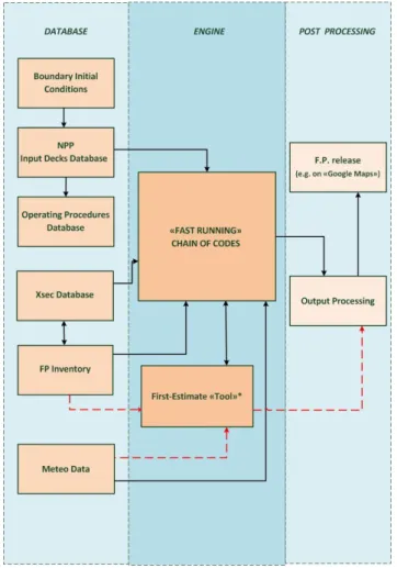
Figure 1 – Structure of the “Fast-running” Chain of Codes. ... 11
Figure 2 – European NPP Map ... 13
Figure 3 – “Standard” Chain of Codes ... 17
Figure 4 – DAKOTA S/U tool ... 19
List of Tables
Table 1. PWR Types ... 13
Table 2. BWR Types ... 14
Table 3. VVER Types ... 14
Acronyms
1D One Dimensional
3D Three Dimensional
AOO Anticipated Operation Occurrence
BE Best Estimate
BDBA Beyond Design Basis Accident
BWR Boiling Water Reactor
CRESCO Centro computazionale di RicErca sui Sistemi COmplessi
DBA Design Basis Accident
ETSON European TSO Network
FLOPS FLoating-point Operations Per Second
FP Fission Products
HPC High Performance Computing
INL Idaho National Laboratory (USA)
IRSN Institute de Radioprotection et de Sureté Nucléaire (France)
LWR Light Water Reactor
OECD/NEA Nuclear Energy Agency of the OECD
OP Operating Procedures
OS Operating System
NK Neutron Kinetics
NPP Nuclear Power Plant
NRC US Nuclear Regulatory Commission
PWR Pressurized Water Reactor
SA Severe Accident
S/U Sensitivity & Uncertainty
TH Thermal-hydraulics
TSO Technical Support Organization
1. Introduction
The development of a “fast-running” chain of codes for simulating Nuclear Power Plants (NPP) status during a severe accident is one of the activities performed by ENEA for its qualification as Italian Technical Support Organization (TSO) for the National Nuclear Safety Authority.
Part of such activities are being developed in an international framework, thanks to research projects and benchmark exercises performed with French TSO (IRSN) and USA Safety Authority (NRC), OECD/NEA, IAEA and the ETSON.
As detailed in [1], the scope of Task B1 of the ENEA-MSE AdP 2012, was the development of a methodology for the safety evaluation during accidents and pre-accident phases. The application of it to could in principle give to Italy the capability to estimate the environmental impact, on the Italian homeland, of a nuclear accident in a foreign neighboring Country.
Preliminary activities were a kind of “testing-activities”, devoted to:
the definition of a simplified source term for a PWR [2];
the calculation by a sample MELCOR Severe Accident (SA) analysis of a
PWR Station Black-Out (SBO) [3] accident;
the definition of software characteristics for handling the NPP database and for
extracting the relevant information (source term as function of the considered event) [4].
The final product of such activities should be an “intelligent database” to be used in
the first phases of a nuclear accident (e.g., hours, first day). Such tool has to be intended as a simplified, strongly conservative tool for deriving a first-hand estimate of the radioactivity release giving a rough indication of how much of such release could affect the Italian homeland.
Therefore, in order to overcome some intrinsic limitations of such approach, and in order to give also an independent analysis of the NPP accident, a complementary tool has to be set-up. Such complementary tool should be able:
to perform “fast-running” (i.e., real-time or faster) analysis of the accident;
to be activated in short-time (i.e., the day after the beginning of the accident);
to perform the analysis with a sufficient level of details for simulating all the
relevant phenomena
to perform several parallel sensitivity & “cliff edges” analyses of the event;
to identify the most important scenarios to be evaluated, depending by a set of
This report briefly describes the architecture of the “fast-running” chain of codes, taking into account the specifications listed above and considering the state-of-the-art in the simulation of the NPP.
In Chapter Two it recalled its scope, the input requirements, the feedbacks/links with other tools, and its target application (EU NPP).
In the Chapter Three a summary of the so-called “best-estimate” tools is given, describing also their combined use (“standard chain of codes”) for multi-physics/multi-scale applications. Reference is made to the UTFISST-Siming Lab simulation platform.
In the Chapter Four it is explained how this “chain-of-codes” should be
modified/integrated in order to obtain the desired “fast-running” platform for accident analyses: parallel calculations of multiple scenarios, simplified tools/input decks, identification of the most important evaluated scenarios.
Finally in Chapter Five the conclusions and the anticipated future steps are described.
2. Input Database & Target Application
2.1 The issue
As recalled in the previous Chapter, the “fast-running” chain of code should be able to analyze an EU NPP accident, giving a best-estimate of the possible radionuclides releases depending on the scenario and on the different uncertainties.
Since the tool should be ready to be used in a day since the beginning of the accident, some relevant information should be prepared in advance (see below). Feedbacks/links with the other first-estimate tool (rapid-access database) being developed should also be guaranteed.
Relevant information about EU NPP should also be available and stored in ad-hoc databases. A scheme of the information fluxes is given in Figure 1.
2.2 Input database
As it is summarized in Fig. 1, a comprehensive database should be set up well in advance. It should contain the following information:
a qualified TH & 3D NK input decks database for the most representative EU
NPP (see below). Such input decks should describe:
o the primary and secondary coolant systems (secondary up to the MSIV)
o the NPP containment
o the reactor core
o the fuel basic thermo-mechanical characteristics
a homogenized two group XSEC database, parameterized as function of
burnup (e.g., from 0-60 GWd/tHM)
a Fission Product (FP) inventory database, also parameterized as function of
burnup and of fuel type
a Meteorological database, representing the atmospheric boundary conditions
(mainly wind directions, orography)
an Operating Procedure (OP) database, distinguishing (OP) among the
different NPP types, and linked to the TH input decks database
Database security should be addressed, as well as compatibility with different codes and code versions employed. Moreover, some information included in this database (e.g., FP and Meteo database, will be directly used also by the other “first-hand” estimate tool for emergency analysis).
2.3 Feedback with other tools
Feedback from the “first-hand” estimate tool should be considered by the “fast-running” chain of codes, since such tool could give some conservative analysis of the accident, providing a top-bounding estimate of the radionuclide emission. Anyway, because of its simplified and conservative structure, no detailed information about the NPP status could be inferred from it.
2.4 Target Application: EU NPP
The following is a tentative list of the main EU NPP types that should be included in the Database. These are considered the target applications of the “fast-running” chain of codes. Some priority should be given to the NPP closer to the Italian border (see Figure 2). Reference units could be considered as representative for each group (e.g., Bugey for French-1, Oskarshamn-2 for Swedish-1, Kozloduy-5 for VVER-1000, etc.). Since the Advanced Gas Reactors (AGR), currently operated just in the United Kingdom, are going to be shut-down in the next 5-10 years, they are not considered as a target application.
Figure 2 – European NPP Map
2.4.1 PWR
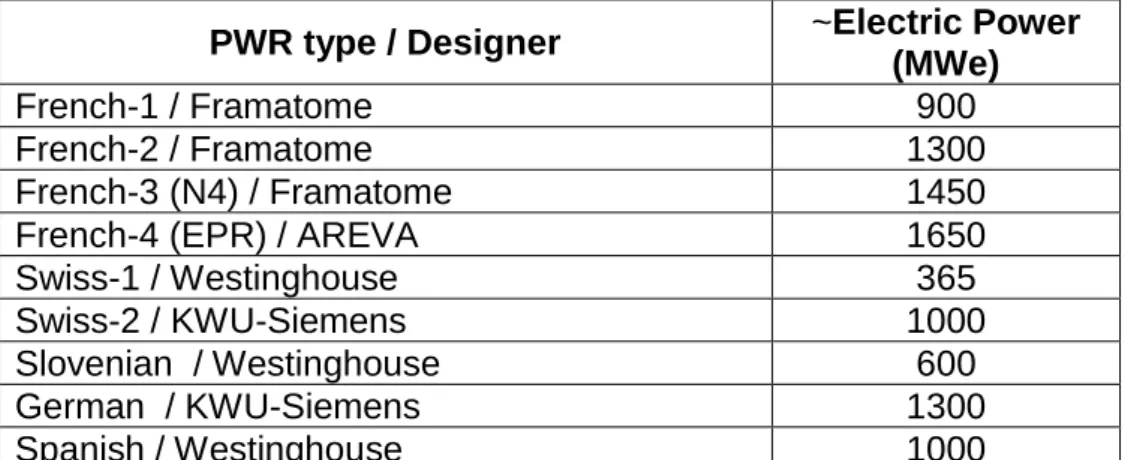
PWR are the most popular NPP type installed in Europe. A proposed grouping could be the following one (see Table 1).
Table 1. PWR Types
PWR type / Designer ~Electric Power
(MWe)
French-1 / Framatome 900
French-2 / Framatome 1300
French-3 (N4) / Framatome 1450
French-4 (EPR) / AREVA 1650
Swiss-1 / Westinghouse 365
Swiss-2 / KWU-Siemens 1000
Slovenian / Westinghouse 600
German / KWU-Siemens 1300
2.4.2 BWR
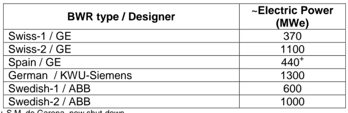
The largest BWR fleet was operated by Germany, but most of these NPP were shut-down following the Fukushima accident. A proposed grouping could be the following one (see Table 2).
Table 2. BWR Types
BWR type / Designer ~Electric Power
(MWe) Swiss-1 / GE 370 Swiss-2 / GE 1100 Spain / GE 440+ German / KWU-Siemens 1300 Swedish-1 / ABB 600 Swedish-2 / ABB 1000
+ S.M. de Garona, now shut-down
2.4.3 VVER
Russian designed VVER reactors are installed mostly in Eastern Europe (two also in Finland). A proposed grouping could be the following one (see Table 3).
Table 3. VVER Types
VVER type / Designer ~Electric Power
(MWe)
VVER440 – mod. 213 / Gidropress 440
VVER1000 – mod. 320 / Gidropress 1000
2.4.4 CANDU
Two CANDU reactors are operated in Europe, at Cernavoda, Romania. Plans for construction of two more units are being considered, therefore it is proposed to include also this technology into the NPP database (see Table 4).
Table 4. CANDU reactors
CANDU type / Designer ~Electric Power
(MWe)
3. Simulation Tools
In the following paragraphs the state-of-the-art of BE nuclear simulation tools are briefly reported. Some of these are already integrated/used in ENEA simulation platforms [5], [6], while some other are just listed, depending by their capabilities and diffusion.
3.1 Fuel Pin Mechanics
Several fuel pin mechanics codes are available and used in simulation platforms. The most used ones are FRAP [7], TRANSURANUS [8], BISON [9]. They allow to perform at least a 1D mechanical simulation of the fuel pin, calculating stresses and strains (elastic and plastic), clad oxidation, gas gap pressure, pellet temperature, burnup effects, etc. Models of the FRAP code are also directly integrated into the RELAP5-3D code, allowing to calculate some relevant fuel pin mechanic parameters without the need of an independent tool.
3.2 Neutronics
Two kinds of neutronics codes are used for an integral simulation of a LWR: lattice physics codes (e.g.: HELIOS [10], SCALE [11], etc.) and core simulators (e.g.: NESTLE [12], PHISICS [13]). The role of the first group is to prepare a set of homogenized two-groups cross section database being used by the core simulators for deriving the 3D flux and power distributions inside the core. Such cross-section database has to be prepared well in advance because of the large amount of computational resources needed. Moreover, it has to be parameterized as function of burnup, of burnup history and as function the most relevant core parameters (e.g., fuel and coolant temperature, boron concentration, etc..).
3.3 Thermal-hydraulics system codes
TH system codes are the backbone of every “chain of codes” for NPP simulation.
CATHARE [14], TRACE [15] and RELAP5/RELAP5-3D [16] are among the most used.
They allow to perform Best-Estimate (BE) analyses, analyzing the coupled behavior of the reactor coolant system and the core for loss-of-coolant accidents and operational transients such as anticipated transient without scram, loss of offsite power, loss of feed-water, and loss of flow.
Control system and secondary system components are included to permit modeling of plant controls, turbines, condensers, and secondary feed-water systems.
3.4 Containment
Containment codes such as GOTHIC [17] or COCOSYS [18] are generally used for performing analyses of the containment behavior. RELAP5-3D can also be used, with some limitations, by employing special modelling techniques.
3.5 Severe Accident
Severe Accident codes such as SCDAP [19], MELCOR [20] and MAAP [21] model the fuel degradation during the SA. They are capable of estimating the fuel melting modes and the induced phenomena like corium-concrete interaction, reactor pressure vessel bottom degradation, FP releases, hydrogen formation and combustion, etc..
3.6 Offsite releases
Offsite release codes allow to calculate the radionuclide dispersion (generally in a radius of tens of km from the NPP) by using simplified meteorological models. They are also capable of estimating the equivalent dose for the plant personnel and for the external population. An example of such codes is the MACCS code [22].
3.7 Other Models (I&C, electrical, CFD, etc.)
Additional tools are being used for modelling very specific parts of a NPP or phenomena.
Some of these tools are being used for on-line calculations while others, because of the intensive computational resources needed, are generally used off-line for deriving boundary conditions.
As an example, Instrumentation & Control (I&C) [23] is generally modelled by ad-hoc software or external routines directly coupled to a TH system code. On the other hand, CFD [24] codes are used for defining in advance some boundary conditions for replicating by TH system codes complex flow paths, pressure losses, heat exchange coefficients, boron concentrations, etc. Structural mechanics coupled to CFD codes are also used for calculating fluid-structure interactions from internal (e.g., pipe whip) or external events (e.g. tornado, hurricanes,..).
3.8 “Standard” Chain of Codes
As an example, here a “standard” chain of codes it is reported. With “standard”, it is indicated its use for safety analyses and design activities. A scheme of its main components is given in Figure 3.
4. “Fast-running” Chain of Codes
4.1 Sensitivity Tools for parallel running
The “fast-running” chain has to be able to give, in a limited amount of time (e.g., days, week), information about the possible states of the analyzed NPP.
Therefore, the capability to run multiple simulation cases in parallel has to be exploited. Fortunately, recent progresses in computational technology allow to perform parallel calculations also on desktop PCs with multi-core and hyper-thread technology. On a larger scale, ENEA CRESCO project [25], gives also the access to a high performance-computing (HPC) platform with a peak performance of more than 100 TFlops.
Thus, “chain-of-codes” like the ones described here, can be an enormous aid for
understanding the complex physical systems they simulate. Simulations may be used not just for single-point predictions, but also for automated determination of system performance.
In order to perform consistent analyses of multiple scenarios, the “fast-running” simulation chain has to be equipped with a software capable of automatically perform Sensitivity/Uncertainty (S/U) analyses. In this way the analysts could obtain:
a set of boundary results for every investigated scenarios, considering the
input and modelling uncertainties
a set of bounding scenarios, resulting from the analyses of possible cliff-edge
effects induced by those uncertainties
quantification of the results confidence level.
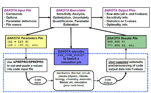
Several S/U tools are already available for such kind of automated analyses [26], [27]. An example of the one being considered by the ENEA-Simulation Lab (UTFISST SIMING), the DAKOTA tool, is given in Figure 4.
Figure 4 – DAKOTA S/U tool
The DAKOTA (Design Analysis Kit for Optimization and Terascale Applications), toolkit, developed by the Sandia National Laboratory (SNL), provides a flexible, extensible interface between analysis codes and iterative systems analysis methods. In facts, DAKOTA contains algorithms for:
optimization with gradient and non-gradient-based methods;
uncertainty quantification with sampling, reliability, stochastic expansion, and
epistemic methods;
parameter estimation with nonlinear least squares methods;
and sensitivity/variance analysis with design of experiments and parameter
study methods.
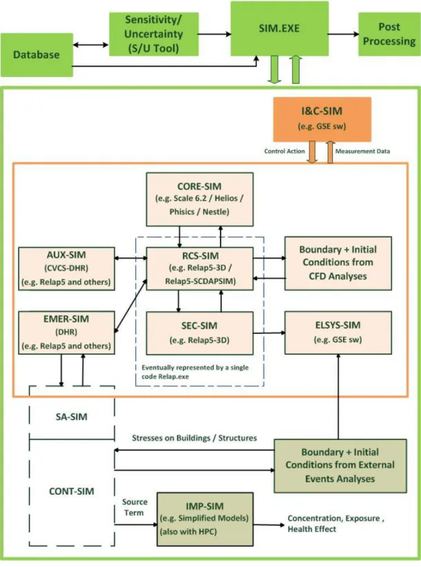
The role and the relation of the S/U tool with the other objects of the “fast-running” chain of codes is described in the sketch of Figure 5.
4.2 Calculations speed-up
The strategy for speeding-up calculations could rely not only on parallel calculations of sensitivities and different scenarios, but also on the simplifications of the software and of the input decks.
4.2.1 Use of “simplified” software
Several companies have developed “simplified” nuclear software for achieving “real
example of this “simplifications” is the RELAP5-HD, developed by GSE Systems Inc [28].
Another tool that could also be used for “fast analyses” in the SA domain is the MAAP code [21], also integrated by GSE in their simulation platform.
It is important to note that such proprietary software cannot be integrated in an ENEA “fast-running” platform without buying the software licenses. Possibility of direct software modification (access to the source code) is also not easily guaranteed.
4.2.2 Input deck simplifications
Procedures for consistent input deck simplifications should be developed and implemented in creating the NPP input decks database. Particular care should be taken in preparing consistent sets of input decks for the different probable scenarios (e.g., MSLB, SBLOCA, LBLOCA), minimizing the number of nodes and (for codes like RELAP), maximizing the Courant time.
The core modelling should also be managed with particular care, avoiding large number of parallel channels and taking into account as much as possible core symmetries.
Auxiliary systems, should be possibly modeled as boundary conditions for saving computational time.
4.3 Post-processing and relevant scenarios identification
A post-processing tool for analyzing the multiple set of data obtained by the parallel calculations should be acquired or developed.
Such tool should be able to:
process the data derived from the different codes outputs composing the
“fast-running” chain of codes
group the set of sensitivities results, showing the uncertainty bands and the
confidence levels
ease the analyst work in identifying the scenarios with the highest risk
plot the ultimate data set of the whole platform (i.e., the FP release
concentration) on a suitable visualization tool, showing the radionuclides dispersion into the environment (e.g., a “Google-map” plot)
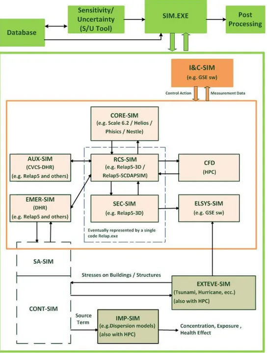
In Figure 5 the proposed general scheme for the “fast-running” chain of codes platform is reported. The relations between the main engine (fast-running codes), modified (i.e., simplified) NPP database, S/U tool and post-processing tools is shown. Depending on the codes selected for the main engine, the “fast-running” chain could run on Windows or Linux/Unix OS.
As it can be noticed, the main difference with the “standard” chain of codes reported in Figure 3 is the use of boundary conditions coming from CFD and
structural-mechanics codes. The direct use of such tools should be avoided in a “fast running”
5. Conclusions
The basic architecture of a “fast-running” chain of codes for simulating in real-time accident in EU NPP has been summarized in this report. The main components of it has been identified:
a qualified database (NPP input decks, OP, FP sets, etc.)
a “fast-running” set of codes/input decks, capable of achieving real-time or
faster-than-real simulations. This should be achieved by parallel calculations, codes/input decks simplifications, HPC
a S/U tool, for obtaining a confidence value for the results and for multiple
scenarios identification
a post processing tool, for an easy processing of the outputs and for the
identification of the situations with higher risk.
Some preliminary activities has been already carried out (see Annex I), also in this and in the previous AdP between MSE and ENEA. The future steps will involve the development of the still missing parts. A sample calculation of a SA event on a EU NPP could help in better identifying the needs.
6. References
1. Accordo di Programma MSE-ENEA sulla Ricerca di Sistema Elettrico - Piano
Annuale di Realizzazione 2012
2. AdP MSE/ENEA. “Rapporto tecnico sui calcoli di inventario di nocciolo”,
Report LP1.B1_a
3. AdP MSE/ENEA. “Rapporto tecnico sui calcoli per la caratterizzazione dei vari
impianti nucleari in condizioni di incidente grave”, LP1.B1_b
4. AdP MSE/ENEA. “Realizzazione di un database esperto per supportare la
gestione di una situazione di crisi”, LP1.B1_c
5. F. Bassenghi, G. Bornia, L. Deon, S. Manservisi, P. Meloni, M. Polidori,
“Implementation and validation of the NURISP platform”, NNFISS-LP5-020, September 2011
6. M. Sepielli, E. Negrenti, C. Parisi, M. Cappelli, “The Role of Thermal-hydraulic
System Codes in NPP Engineering Simulators and the ENEA Strategy”, 20th
International Conference “Nuclear Energy for New Europe 2011”, Bovec, Slovenia, September 12-15, 2011
7. L.J. Siefken et al. FRAP-T6: A computer code for the transient analysis of
oxide fuel rods , NUREG/CR-2148, EGG-2104 (May 1981)
8. Lassmann, K., et al., “TRANSURANUS Handbook”, 2005
9. R. L. Williamson, J.D. Hales, S.R. Novascone, M.R. Tonks, D.R. Gaston, C.J.
Permann, D. Andrs, R.C. Martineau, “Multidimensional Multiphysics Simulation of Nuclear Fuel Behavior,” Journal of Nuclear Materials, Vol. 423, pp. 149-163, 2012
10. HELIOS methods
(http://www.studsvik.com/Documents/Product-sheets/Updated %20product%20sheets%20SSP/helios.a4_el.pdf)
11.SCALE: A Comprehensive Modeling and Simulation Suite for Nuclear Safety
Analysis and Design, ORNL/TM-2005/39, Version 6.1, Oak Ridge National Laboratory, Oak Ridge, Tennessee, June 2011.
12. NESTLE 6.1Code Manual, Electric Power Research Center, Raleigh, North
13. C. Rabiti, Y. Wang, G. Palmiotti, A. Epiney, A. Alfonsi, H. Hiruta, J. Cogliati, T. Grimmet, “Advanced Neutronics: PHISICS”, IRUG Seminar, July 26-28, 2011 Salt Lake City, UT, USA
14.“CATHARE: Advanced Safety Code for Pressurized Water Reactors”,
(http://www-cathare.cea.fr )
15.Mahaffy, J. H., Uhle, J., Dearing, J., Downar, T., Johns, R., and Murray, C.,
“Architecture of the USNRC Consolidated Code”, 2000a, Proceeding of
ICONE 8, 8th International Conference on Nuclear Engineering, Baltimore, MD
USA, April 2-6, 2000
16.RELAP5-3D© Code Manual Volume I: Code Structure, System Models and
Solution Methods, INEEL-EXT-98-00834, Revision 4.0, July 2012
17.R. Ofstun, "Development and Qualification of a GOTHIC Containment
Evaluation Model for the Kewaunee Nuclear Power Plant”, WCAP-15427, Rev. 1, April 2001 (WCAP-l15667 is the non-proprietary version).
18.H. J. Allelein, S. Arndt, W. Klein-Heßling, S. Schwarz, C. Spengler, G. Weber,
“COCOSYS: Status of development and validation of the German containment code system”, Nuclear Engineering and Design, Volume 238, Issue 4, April 2008, Pages 872–889
19.C. M. Allison, J. K. Hohorst, “Role of RELAP/SCDAPSIM in Nuclear Safety”,
Proceeding of TopSafe Conference, Dubrovnik, Croatia (2008)
20.R. O. Gauntt et alii, “Melcor computer code manuals”, Sandia National Lab,
May 2001
21.Fauske & Associates, “MAAP4 code” (http://www.fauske.com/pdf/MAAP.pdf)
22. “MACCS2 Computer Code Application Guidance for Documented Safety
Analysis”, DOE-EH-4.2.1.4-MACCS2-Code Guidance, June 2004
23.“JControl™ JADE™ Control Logic Modeling Software”
(http://www.gses.com/images/datasheets/GSE-JControl-datasheet.pdf)
24.ANSYS CFX, v. 13.0, (www.ansys.com)
25.CRESCO, “Centro Computazionale di Ricerca sui Sistemi Complessi”,
26.A. Alfonsi, C. Rabiti, D. Mandelli, J. Cogliati, R. Kinoshita, “Performing Probabilistic Risk Assessment Through RAVEN”, ANS, Annual Meeting, June 16-20, 2013, Atlanta, Georgia, USA.
27.B. M. Adams et alii, “DAKOTA, a multilevel Parallel Object-Oriented
Framework for Design Optimization, Parameter Estimation, Uncertainty Quantification, and Sensitivity Analysis”, Version 5.3.1+ Developers Manual, SAND2010-2185, Unlimited Release, December 2009, Updated May 22, 2013
28.RELAP5-HD,
Annex I
NURETH-15 Conference Paper
Pisa, 12-17 May 2013
A PRELIMINARY ANALYSIS OF THE UNIT 1 ACCIDENT AT THE
FUKUSHIMA DAICHI NPP BY THE RELAP/SCDAPSIM CODE
C. Parisi, A. Del Nevo, E. Negrenti, M. Sepielli
ENEA “Casaccia” Research Center Santa Maria di Galeria, 00123, Rome, Italy
[email protected], [email protected], [email protected], [email protected],
ABSTRACT
In the framework of the activities devoted to the development of the ENEA-Casaccia “NPP Engineering Simulator”, a RELAP5/SCDAPSIM model of the unit 1 of the Fukushima Daiichi NPP was developed and applied for a severe accident analysis. In this paper the preliminary results are reported. In order to correctly describe the main phenomena, a detailed nodalization of a BWR-3 primary system and of Mark I containment were developed and coupled. BWR-3 NPP public available data of a similar unit were used for setting up the RELAP/SCDAPSIM model and for performing its steady state and transient validation. Main events reconstruction of the Fukushima scenario was based on the official Japanese data. The first 24 hours of the accident were simulated, beginning with the reactor scram as a consequence of the earthquake, and reproducing the behavior of the main engineered safety features (safety/relief valves, isolation condensers). Results showed that the core uncovering and degradation began at +2 hours after the tsunami wave hit the plant. Core melting was predicted having occurred in the subsequent 6 hours, with a fuel relocation at the bottom of reactor pressure vessel. RELAP/SCDAPSIM special models calculated the severe damage of the reactor boundary allowing to estimate the time of the consequent containment over-pressurization that resulted well beyond the design limits. Calculations ended at the time of the actuation of the containment venting procedures since they were immediately followed by a major hydrogen explosion in the reactor building. Sensitivities analyses were performed to test the different RELAP/SCDAPSIM models of core degradation and a bounding range for the main parameters involved during the core degradation was obtained. This work constitutes also an example of the present capabilities and one of the steps being performed
at the ENEA-Casaccia Research center for the reintroduction of a “Enhanced NPP Engineering Simulator”.
1. Introduction
In the framework of the nuclear research activities in the fields of safety, training and education, ENEA (the Italian National Agency for New Technologies, Energy and the Sustainable Development) is performing various activities devoted to the development of the ENEA-Casaccia “Enhanced NPP Engineering Simulator”. One of the actions occurred during the last year was the acquisition of the RELAP5/SCDAPSIM code [1] and the development of a model for the severe accident analysis of the unit 1 of the Fukushima Daiichi NPP. The RELAP/SCDAPSIM code was selected since the events simulation required a code with the capabilities to model the thermal-hydraulic phenomena inside reactor pressure vessel (RPV) and the containment as well as the thermo-mechanical behavior of the fuel and of the RPV. This paper presents a brief overview of such work. The description of the thermal-hydraulic modelling of the reactor, of the engineered safety features and of the containment is given. Then the nodalization qualification process is illustrated. The main events occurred at Fukushima Daichi unit 1 are recalled according to the present knowledge and the preliminary results of the simulations of the accident is showed. The effects of some relevant parameters on the simulation results are also investigated and presented. In the last paragraph, the conclusions and the connections with the ENEA ongoing and future activities are presented.
2. The RELAP/SCDAPSIM Model
2.1 The Reactor and the Reactor Coolant System
Fukushima Daiichi unit 1 is a BWR-3 reactor, equipped with isolation condensers [2], [3]. A thermal-hydraulic (TH) model was developed, including the RPV, the Steam lines, the Safety & Relief Valves (SRV/RV), the Isolation condensers (IC) and the two recirculation lines. The turbine and the turbine bypass were also modelled by time dependent volumes. Active and passive heat structures were used for modelling the nuclear fuel and the materials of the RPV and of the reactor coolant system. The active core was modelled by five independent TH channels. Moreover, one TH channel was used for modelling the radial reflector and other five independent TH channels were used for modelling the moderator bypass and associated with the RELAP/SCDAPSIM control rod blade model. GE 8x8 fuel assembly (FA) data was used and appropriate peaking factors and axial power shape were imposed. ICs
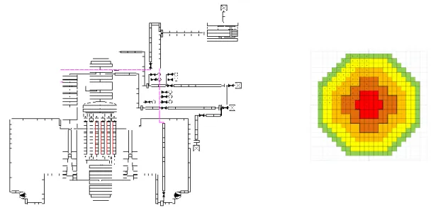
were modelled and connected to the upper part of the downcomer (DC) and to the two recirculation lines. All the SRV/RV were modelled using opening and closing set points reported in Japanese documentation [2]. In Figure 1 the RELAP/SCDAPSIM TH nodalization scheme and the core radial scheme are reported.
Figure 1. RELAP/SCDAPSIM TH nodalization scheme (left) and core modelling (right)
The whole nodalization is composed by around 1000 volumes and 500 heat structures. The geometrical data for setting up the RPV model and the reactor coolant system was retrieved by public available data of an identical unit [4].
2.2 The Containment
MARK I type containment is present at the Fukushima Daiichi unit 1. This containment type was modelled using a special RELAP/SCDAPSIM nodalization scheme which is reported in Figure 2. The bulb-shaped drywell (DW) and torus-shaped wetwell (WW) were represented using a series of pipes and branches preserving the volumes of the relevant sections. The venting sytem (header and downcomers), the spargers and the vacuum breakers were also modelled.
009 008 007 006 005 004 003 002 011 010 001 015/016 017/018 Drywell 020/022 024/026 021/023 025/027 Wetwell Vent 035/037 039/041 036/038 040/042 030/031 032/033 Vacuum BRK 045 Safety VLV Safety/relief VLV
Figure 2. RELAP/SCDAPSIM TH nodalization of the MARK I containment
The containment nodalization was coupled to the reactor nodalization via the SRV/RVs, discharging into the wetwell liquid volumes and into the drywell atmosphere.
3. Model qualification
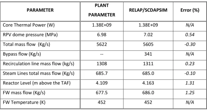
A preliminary steady-state qualification was achieved by running a null transient and by verifying the main plant parameters. BWR-3 steady state data of a twin unit was used [4]. Results are showed in Table 1.
PARAMETER PLANT
PARAMETER RELAP/SCDAPSIM Error (%)
Core Thermal Power (W) 1.38E+09 1.38E+09 N/A
RPV dome pressure (MPa) 6.98 7.02 0.54
Total mass flow (Kg/s) 5622 5605 -0.30
Bypass flow (Kg/s) -- 341 N/A
Recirculation line mass flow (kg/s) 1308 1311 0.23
Steam Lines total mass flow (Kg/s) 685.7 685.0 -0.10
Reactor Level (m above the TAF) 4.109 4.163 1.31
FW mass flow (Kg/s) 677.5 686.0 1.25
FW Temperature (K) 452 452 N/A
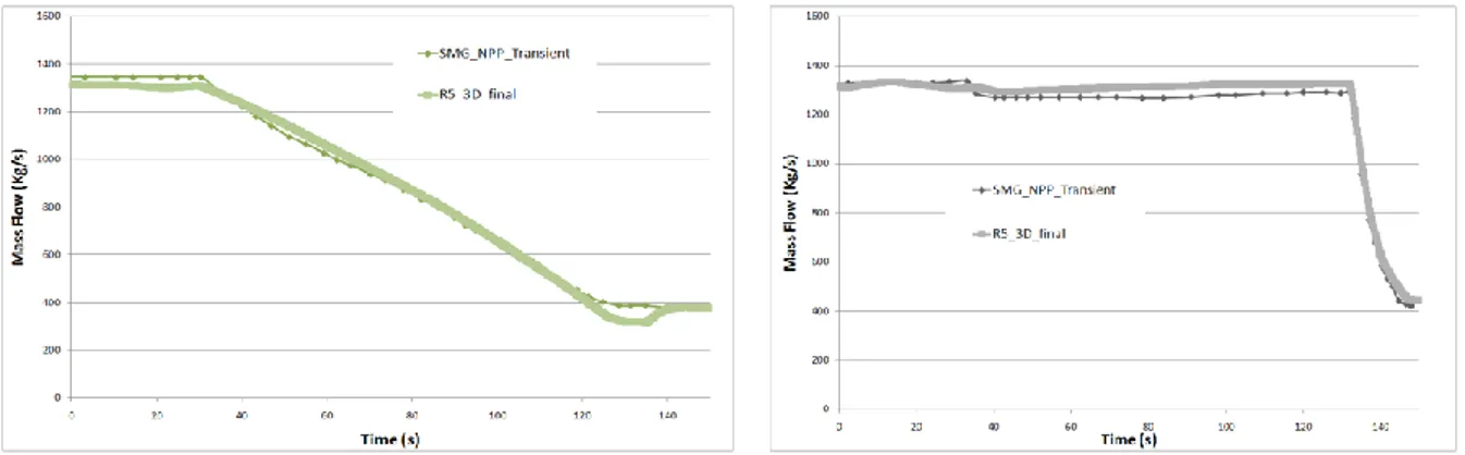
The successive step was the on-transient qualification. This was achieved by reproducing a turbine trip event occurred in a similar unit [5] in the 1992 and by checking some of the main parameters. Results are reported in Figure 3 and Figure 4, showing the trends of reactor pressure dome, the core and the recirculation lines mass flows. A good qualitative agreement is demonstrated by such calculations.
Figure 3. On-transient qualification: Core Mass flow (left), Steam Dome pressure (right)
Figure 4. On-transient qualification: Recirculation line mass flows, line A (left), line B (right)
4. The Fukushima Daiichi Unit 1 Accident Simulation
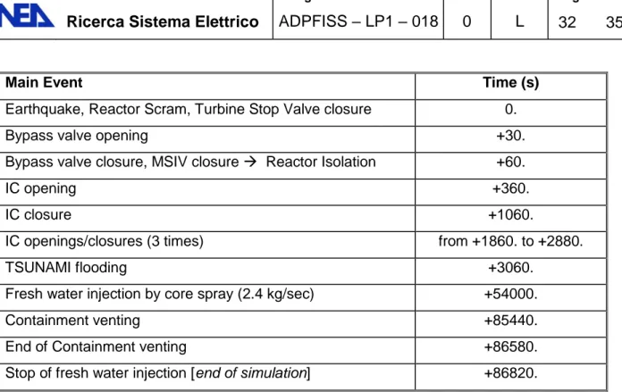
Events reconstruction at unit 1 was performed by using Japanese official documentation [2]. In Table 2, the main sequence of events simulated by the RELAP/SCDAPSIM model is given.
Main Event Time (s)
Earthquake, Reactor Scram, Turbine Stop Valve closure 0.
Bypass valve opening +30.
Bypass valve closure, MSIV closure Reactor Isolation +60.
IC opening +360.
IC closure +1060.
IC openings/closures (3 times) from +1860. to +2880.
TSUNAMI flooding +3060.
Fresh water injection by core spray (2.4 kg/sec) +54000.
Containment venting +85440.
End of Containment venting +86580.
Stop of fresh water injection [end of simulation] +86820.
Table 2. Main events simulation time
The main assumption in the simulation is that no reactor cooling was anymore achieved after the tsunami flooding because of the total station blackout and the loss of the passive cooling by the ICs. Some reactor cooling was re-established by using the core sprays several hours later. Containment venting was imposed after roughly 24 hours from the beginning of the events. Simulation was stopped immediately after, because of the hydrogen explosion that occurred into the reactor building.
Seven phases of the accident were identified and simulated:
Phase 1 : scram, by-pass pressure control, reactor isolation by main steam isolation valves (MSIV) closure [0-60 secs]
Phase 2 : energy removal by the ICs [+360 to 3060 secs]
Phase 3 : End of cooling (stop of ICs), loss of RPV inventory, water level decreasing down to the Top of Active Fuel (TAF) [ ~ 3060 secs to +7000 secs (2hr)]
Phase 4: Core uncovery and degradation, H2 formation, core voiding [from +2hr to
+3.4/4 hrs]
Phase 5: Core melting [+3.4/4 hrs to 3.8/8 hrs]
Phase 6 : RPV bottom damage and break [+3.8/8 hrs to +15 hrs]
Phase 7: Containment over-pressurization and venting [+15 hrs to +24 hrs]
The results of the reference calculations are showed in the figures below. In Figure 5 the IC-A level and ICs mass flows are showed. Their role was relevant for the decay heat removal during the first phases of the accident. In this simulation they were conservatively supposed to completely cease the operation after the tsunami wave. It should be noted that this is a point that is still being discussed by the Japanese authorities.
Figure 5. Isolation Condensers A&B Mass Flows and IC-A Level
Because of the loss of cooling by ICs and because of the loss of mass inventory via the SRV, the RPV level decreases, reaching the TAF in 2 hours. As it can be seen in Figure 6, the melting of the clad is then occuring in the successive 2 hours.
Figure 6. RPV DC and in-shroud level, Hot spot clad temperature
RPV pressure pressure is kept constant by the actuation of the SRV that on the other hand causes a slow increase of the containment pressure (see Figure 7). A large drop into the RPV pressure was registered by the NPP instrumentation [6] and it was modelled in the simulation by imposing a RPV lower head break (see Figure 7). This loss of RPV integrity is supposed to be caused by the degradation effects caused by the fuel slumping in the bottom part of the lower plenum and it is calculated by the COUPLE module of the RELAP/SCDAPSIM. Consequently, because of the energy released into the containment by the lower plenum break and because of the H2 releases, the containment pressure spikes
around 0.8 MPa. The COUPLE module then correctly predict the energy transfer from the molten fuel still kept into the lower head and the containment atmosphere (see Figure 8). The successive pressure drop, several hours later, is obtained by simulating the containment
venting [6]. Such procedure led to the hydrogen explosion into the reactor building in the real NPP.
Figure 7. RPV and Drywell pressures
Figure 8. Containment pressure – COUPLE on/off model sensitivity
Several sensitivities were run in our preliminary calculations in order to assess the effect of the various RELAP/SCDAPSIM code models on the transient evolution. One example of such sensitivities is showed in Figure 9, where a couple of modes of core degradation are represented. In particular, on the left part of the picture, the degradation sequence led to the complete core slumping in 7.2 hours, while, on the right part, the degradation sequence resulted in a major core melting in 8.3 hours.
L I I L I V V L I I V V I I I V V V I I V V V V V V V V P P V V V P I P P P I I I I I I I I I I I I I I I I I I I I I I I I I I I I I I I I I I I I I I I I I I I I I I I I I I I I I I I I I I I I I I CENTER PERIPHERY V V V V P V V V V I V V V V P V V V V V V V V V V V V V V V V V V V V V V V V V V V V V V V V V V V V V V V V V V V V V V V V V V V V V V V V V V V V V V V V V V V V V V V V V L V V V xxMxx I V L V L I xxMxx CENTER PERIPHERY I I I I I I I I I I I I I I I L I I I I L L L I I V L L I I V V L I I V V V L I xxMxx xxMxx xxMxx P I xxMxx xxMxx L I I L P I I I I I I I I I I I I I I I I I I I I I I I I I I I I I I I I I I I I I I I I I I I I I I I I CENTER PERIPHERY L I I I I V V V I I V V V L I V V V V I V V V V I V V V V I V V V V I V V V V V V V V V V V V V V V V V V V V V V V V P V V V V I V V V V I V V V xxMxx I V V V P I V xxMxx xxMxx I I V P xxMxx I I L I P I I I I I I I
A sensitivity analysis was also run for taking into account the loss of mass inventory through the pump seals (~25 gallons per minute were imposed, [7]), resulting in an anticipation of the core degradation by half an hour. Calculation of the total hydrogen production resulted in roughly 480 Kg.
The time sequence of the main events of the reference calculation is presented in Table 3 and it is compared with the analyses performed by Japanese institutions [6] using independent severe accident codes like MAAP[8] and MELCOR [9].
Event ENEA –
R5/SCDAPSIM
NISA -
MELCOR TEPCO - MAAP
Core Exposure 2 hrs 2 hrs 3 hrs
Core Damage 3 hrs 3 hrs 4 hrs
Table 3. Time sequence comparison of the main events estimation by different institutions
5. Conclusions
In this paper a preliminary analysis by the RELAP/SCDAPSIM code of the Fukushima Daiichi unit 1 accident is showed. The analysis was performed by modelling the complete RPV, the reactor coolant system and the containment. Steady state and transient validation was obtained by using available data of a twin unit. The severe accident analysis and the sensitivities calculations performed were able to identify the main occurred phenomena. The time sequence of the events was similar to the ones calculated by the Japanese institutions using different codes and methods. The preliminary comparison of the main calculated values with some plant data also showed some degree of agreement. Nevertheless more activities will be needed in the future in order to qualify the developed model, to implement the new data and test new code models.
The continuation of such work will be part of the efforts being performed at ENEA “Casaccia” Research Center for the reconstruction of the nuclear simulation competences and for the rebuilding of an Enhanced Engineering Simulator.