September 10 -11 2009, Glasgow, UK
EXPERIMENTAL ANALYSIS OF AN INNOVATIVE NITI WIRES ACTIVATED
PNEUMATIC VALVE TO STUDY AND IMPROVE PERFORMANCES
Alberto Borboni, Monica Tiboni, Diego Pomi
Mechanical and Industrial Engineering Department, Università degli Studi di Brescia - Brescia, Italy
Abstract: The paper deals with the design and the experimental analysis of an innovative pneumatic valve
activated by NiTi wires, materials which belong to the so called Shape Memory Alloys (SMA). The novelty of the hereby illustrated valve concerns with the activation device, the shape and the body in polymeric ma-terial. As a consequence, the proposed device shows the following advantages: the easier assembly, the com-pactness, the silently functioning, the bio-compatibility, the low power activation and the production cheap-ness. The static and dynamic characterization of the valve has been performed through a dedicated test bench and a wide range of tests on the valve.
Key words: Pneumatics, valves, NiTi wires, SMA.
I I
NTRODUCTIONDuring these last years, the researches concerning with the pneumatic technology and its being applied in the industrial automation environment [1] have been often focused on the innovation in the design and materials of actuators and valves. The employ-ment of SMA components as pneumatics actuating devices has been the object of various literary contri-butions.
In 1996 Yokota et al. [2] developed a small propor-tional using shape memory alloy array actuators, with nine couples of SMA NiTi wires to open it. Such valve offered very good static and dynamic perfor-mances, with a maximum working frequency of 40 Hz.
In 1997 the NiTi Alloy Company produced a thin film SMA based micro-valve, with potentialities in the fluid flux control [3].
Krulevitch et al. [4] designed a valve with a mem-brane formed by a NiTiCu and silicium composite; the valve opens deforming by heating the membrane. Maffiodo et. al. [5, 6] applied SMA wires to pneu-matic valves.
The prototype of hereby proposed pneumatic valve offers novelty elements in its shape, materials and opening device. The form is very compact, the body has been realized with a mouldable polymeric ma-terial and the activation device is based on NiTi fi-bers wires.
This pneumatic device is a normally closed, two way, monostable valve [7], with The NiTi wires fixed on the plug and integrated to the valve body.
An important role on the global performance is played by the spring used for the return of the valve: it exerts a prestress action on the NiTi wires to guar-antee the normally closed configuration. Thanks to the resistance of the NiTi alloy, the electrical input is converted into thermal energy. As a consequence of their being of their being heated by the Joule effect, the wires contract themselves pulling the plug that opens the valve and let the flow pass through [8]: the compliance of the spring shall permit the valve open-ing, while the spring let the valve to be closed as in the first configuration when the wires cool down. It is suggested to identify standard and recognizable parameters [9] to compare and to examine the real behavior of the valve: the International Standard in-dicates the flow capacity and the main time values as characteristic parameters, respectively for the quasi-static analysis of the valve and for the dynamic one. The static tests have led to the experimental determi-nation of the of the flow rate that passes through the valve under the different working conditions and permit to estimate the load loss and the flow beha-vior. On the other hand, the dynamic tests have been performed to evaluate the response time and the max-imum activation frequency, through the acquiring of the step response and of the device activation fre-quency.
II
LAYOUT OF THESMA
WIRES ACTUATED VALVEDuring the design phase of the valve, the opportunity of inserting the valve into a standard line of pneumat-ic systems has been considered and attention to pects of assemblability, of low-cost production as-pects and of life cycle has been paid. The assembly method of the valve takes into account the chance of using a transfer machine with simple pick-and-place components for its manufacturing.
Thereafter, the designed mesovalve actuated by NiTi wires is shown in figure 1.
The mounted valve has a length of thirty-five milli-meters (35mm) and weights three grams (3g).
Fig. 1. Layout of the pneumatic mesovalve actuated by the NiTi wires: exploded view and photo.
Fig. 2. Components of the valve: 1 brass shutter; 2 conical steel plug; 3 Flexinol wire F 50 μm ; 4 valve
body in Plexiglass with flow exit orifice; 5 internal valve body; 6 spring; 7 stopper with a hole F 4 mm
for air entry.
As shown in figure 2, seven elements compose the valve: the wires (3) are in NiTi fibers, while the body of the valve (5) is in polymeric material.
The manual assembling time amounts to about 15 minutes, with the related steps consisting in the following phases:
a. with a needle, insertion of the two NiTi wires first through the plug hole, then through the spring and finally through the valve body b. joint of the NiTi wires around the relative
cop-per wires, and fix of the heads of the NiTi wires on the brass plug with the conical pin.
c. as final operations, inclusion of the valve be-tween the Plexiglas body and the cap on the op-posite site, , with subsequent sealing of points, where could exist some loss of air.
As the prototypes has a limited number, but the plug behavior had to be properly examined, the body of the valve has been realized with workable plastic materials. For the machined bodies has been chosen a type of Polyamide that is also moldable. Further-more, some plastic materials can be also used by a rapid prototyping system.
III S
HAPEM
EMORYA
LLOY(SMA)
MATERIALSIf submitted to the appropriate thermal proce-dure, the Shape Memory Alloys (SMA) own the proved capability of restoring a predetermined shape or size.
Such materials present a plastic deformation at relatively low temperature and the return to the not deformed shape in case of a well defined thermal exposure.
The shape memory effect (SME) can be asso-ciated to the temperature and to thr stress dependent shift in the material’s crystalline structure while going through the two different phases called marten-site and austenite. The low temperature phase, mar-tensite, is relatively soft whereas the high tempera-ture phase, austenite, is relatively hard. Accurate in-formation related to the SMA behavior of commer-cial materials can be found in [8,10,11].
The most remarkable advantages of using the SMA consist of the consequent: compactness, clean-liness, silently functioning, spark-free actuation, and the significant ratio power/weight; while it shall be also underlined how the performance of these actua-tors is depends on the number of cycles and how con-trol is complex [7].
SMA materials have been applied in many fields: medicine, robotics, mechanics, pneumatics, vibration control, aeronautics, etc… The number of producers of these materials is increasing, so as the related ap-plications and research interest.
IV
FORCES AND VALVE DIMENSIONING During the on-phase of the valve, the force F to be exerted by the NiTi wires for moving the plug shall contrast both the spring force and the force due to the air pressure. The equation (1) allows to calcu-late the maximum force exerted by the spring, while the equation (2) leads to the force due to the pressure. . F k l m = ⋅ Δ (1) p ott F = ⋅P A (2) ott F= ⋅ Δ + ⋅k l P A (3)The value of Fm results comprised between 0,91 N
and 1,27 N (Δl and k are respectively the extension and the elastic constant of the spring), while FP is the
product of the pressure P on the plug area Aott.
In the equation (3), the plug area Aott and the
spring stretch are fixed, the maximum force that the wires can tolerate is known, hence the elastic coeffi-cient k is chosen as low as possible to obtain a wide pressure range. A return spring (a passive mechanical component) maintains the wires correctly stretched and the plug on the closed position by exerting the necessary force and also allows the valve opening after the NiTi wires activation because of its compli-ance.
The different stretch properties of four types of spring were tested, even if the internal diameter and the length had to remain unchanged because of the dependence on the internal Plexiglas housing and on the housing of the closing-pin of the geometrical size. Once a good compromise between the spring stability and the linearity of the force-length ratio has been studied, it is possible to avoid the lateral bending of the spring: after the valve activation, the NiTi wires contract and move the plug. Although the use of the spring is essential for the return to the starting condi-tion of the NiTi wires, this could be a source of unde-sired phenomena: as a matter of fact some tests, with a work frequency higher than 1 Hz, have shown noteworthy lateral bending of the spring and this un-desired behavior is emphasized by an increasing dif-ferential pressure.
The phase transformation from martensitic to auste-nitic requires that the NiTi wires overcome a maxi-mum force coming out from the equation (3). In such equation, the only changing parameter in the valve configuration is the pressure that increases in func-tion of the diameter and characterizes therefore the limit condition, as it is associated to the maximal air pressure resulting when the wires start yielding. The chosen wires configuration is composed by two segments with 100 mm length. As the NiTi wires show a self-contraction of 8% per cycle during the first 100 cycles, a previously tested four wires ver-sion with a shorter length (36 mm) resulted
unsatis-factory because of the sub-consequent displacement (2.8 mm).
V E
XPERIMENTAL ANALYSISTo study the static and the dynamic valve behaviour, to identify important functional parameters and in-put-output variables of the prototypal device, a dedi-cated test-bench was realized and used.
Thanks to the static tests, the flow rate through the valve under different working conditions has been experimentally determined, so as the load loss and the flow behavior.
On the other hand, the response time and the maxi-mum activation frequency have been established by means of the dynamic tests, as also the capability of controlling the step response speed and of changing the activation frequency of the device.
A.
The pneumatic test-bench
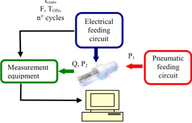
The test-bench functional architecture (figures 3) was conceived to lead the electrical and pneumatic values towards a common measurement interface.
Fig. 3. Test-bench functional architecture. According to the above mentioned characteristic, the test-bench (figure 4) has been designed with four main parts:
1.
the electrical feeding circuit: a PWM system[12] with variables programmable through a microchip supplies the SMA wires with a constant current-step (I cost) at a frequency f
=1/(TON + TOFF) and with a duty cycle changeable for a fixed number of cycles;
2.
the fluid control system: compressed air ishereby generated and the input P1 pressure of the
dry and filtrate air is regulated;
3. the measurement equipment:pressure P2 and flow
Q at the output of the valve are respectively measured by pressure transducer and mass flow meter, with data acquiring devices;
4. data elaboration: by means of a PC and dedicated software. P1 Q, P2 Measurement equipment Icost, F, TON, n° cycles Pneumatic feeding circuit Electrical feeding circuit
Fig. 4. Test-bench
As the air shall have particular properties during the tests to determine the static and dynamic charac-teristics of the valve and to avoid damages of the in-struments, the test-bench pneumatic equipment makes use of compressed air coming from a dedicat-ed generation group. The air is then filterdedicat-ed and de-humidified as requested by the international stan-dards and compressed by a volumetric compressor (max regime pressure P max = 8 bar, regime power W
= 1.5 kW), while a FRL group is used to clean, to filter and to lubricate the air (filter-reducer-lubricator).
To preserve the instruments of the test-bench and to avoid an excessive pressure in the input regulator, a maximum pressure of 6 bar is inserted. Compressed air at 6 bar is thereafter supplied, dehumidified and 20 µm (max dimension of the particulate in the air) filtered.
B.
The static tests
In figure 5 is represented the schematic experimental setup of the test-bench for static test and dynamic tests.
Fig. 5. The experimental setup for the static and dy-namic test (R is the regulator, C the signal, T the transducer, V the valve, F the mass flow meter and
M the data acquisition system).
The electrical signal from the PWM circuit con-trols the valve and an almost constant pressure is pre-served during the test, with only a light pressure de-creasing at the valve opening by means of the plug. The electronic proportional regulator R shall be
therefore, opportunely adjusted: the regulator R can work also as a transducer of the input pressure P1,
while the output pressure P2 is controlled by the
pres-sure transducer T connected crosswise to the air flow direction for avoiding the velocity load. The flow rate Q is measured by the mass flow meter and the link pipes are suggested by the ISO standards: Φ 4, Φ 6 or Φ 8 mm shall be used as pipes diameter for an easy intra pipes connection, without pressure loss and for stan-dard conditions of the internal roughness. At T1=293 K
(ambient temperature), the signal C, the output pressure P2,
the feeding pressure P1 and the flow rate Q are recorded by
the data acquisition system M (Fig. 5). Such tests can provide the effective flow rate Q passing through the valve according to a fixed upstream pressure P1 and
to a measured downstream pressure P2.
Other tests, where a Φ 50 µm diameter is used for the NiTi wires, show how the control of the pres-sure P1 and of the flow rate Q allows to change the
pressure P2 from 0.2 bar (relative) till the maximum
admissible differential of the pressure. In this case, the maximum input pressure is 2.0 bar and the effec-tive flow rate is less than 25 Nl/min
Thanks to the tests, it was possible to reduce the NiTi wires recover time (cooling time): the use of compressed air while the input pressure helps the closure of the plug has shown the inverse proportio-nality between the pressure P2 and the recover time
(experimentally verified), but also that the cooling by means of compressed air carries on during the activa-tion. A part of the energy supplied during the tran-sient phase between austenite and martensite is lost: i.e. at pressure P2 higher than 0.6 bar, the energy
supplied for 200 sec by the Icost 240 mA current is not
able to activate the wire.
To find the flow rate through the quasi-static tests, the regime conditions determination is a fundamental pre-requisite. After its activation, the valve is there-fore maintained opened till the point of constant con-dition and with a 30 seconds recording time. At first, the activation current is fixed on 900 mA with an overpressure P2 of 0,2 bar (corresponding to an
abso-lute pressure of 1.2 bar), then the signal from the mass flow meter is recorded and finally the input pressure is changed till the differential pressure limit.
After the examination of the constrains and the finding of the feeding current to activate the NiTi wires, a set of static tests with the changing of the flow from the input to the output pressure has lead to the calculation of the flow capacity C. This value has been assumed as parameter to compare the prototype with the commercial valves and to characterize the first one. Calculation can follow two way: KV, if the
reference standard is the European Standard EN and the units belong to S.I.; CV, if the reference standard
is the National Bureau of Standard NBR. Many of the affecting factors on the functioning of a generic valve are necessarily to be considered for the flow capacity calculation by means of equations that
ex-press the relationship between flow rate, flow coeffi-cients, related installation factors and pertinent ser-vice conditions for valves handling compressible flu-ids [1].
The flow rate Q, as represented in Fig. 5, is a function of the input pressure P1, while the output
pressure P2 is fixed at 1 bar: the flow rate Q increases
in progressive manner till the pressure P1 has reached
1.6 bar, corresponding to the critical ratio condition between P1 and P2. The over passing of such
pres-sure value means a sonic flow and a straight flow rate line.
Fig. 5.The P-Q curve of the valve with pressure P2
equal to 1bar, where Q is the flow rate, P1 is the inlet
pressure and P2 is the outlet pressure.
Tab. 1 compares the prototype with solenoid commercial valves and reports some technical data of the mesovalve 2/2 actuated by NiTi wires and of the same type actuated by solenoid (KV and CV
calcu-lated at differential pressure of 1 bar). This short comparison shows how the flow coefficient C results improved, even if the characteristics of the SMA valve are equivalent to those of the commercial one.
Type Media Function Operation Ø(mm)
SMA Air 2/2 NC Acting Direct 2.0
Solenoid Air 2/2 NC Acting Direct 1.6
Type Cv Kv Flow Nl/s (Δp=1 bar)
SMA 0.09 1.35 0.41
Solenoid 0.08 1.2 1.7
Tab.1: Technical data of a commercial solenoid mesovalve 2/2 and the experimental data of SMA valve.
C.
Dynamic tests
The below described tests were aimed at finding the dynamic behaviour of the SMA wires valve, as
the dynamic response of the valves assumes a great relevance in many industrial applications
Experimental analysis of input current limits
Fixed parameters have been used for the first tests: I cost 240 mA with a 1 Hz frequency, a 50% duty
cycle and the pressure regulator starts at the relative pressure of 0.2 bar. Under such conditions, the NiTi wires cool down instantaneously because of the com-pressed air, although in case of a reduced air flow. Furthermore, the displacement of the plug with an activation step current Icost equal to 240 mA for 100
ms is much lower than the one obtained in the calm air tests.
As the valve remains almost closed, the NiTi wires changing phase implies that a lot of energy is dissipated by the air flow. The tests are therefore supplied with much more electric energy, afterwards i.e. the step current Icost is equal to 500 mA or 900
mA.
To study currents limits, a step signal is given as
input with the following parameters: Icost is 900
mA, with TON equal to 0.9 s, TOFF is not defined and
P1 is equal to 0.2 bar.
Fig. 6. Pressure response to current step signal with: Icost =900 mA, TON = 0.9 s and P1 = 0.2 bar.
The response signal (fig. 6) has a noteworthy overshoot, but only some of the data from the graphic are interesting: the activation time t1, the response
time t∞ (when the response follows the regime line)
and regime line y∞. The marked line of Fig.7 is the
running-mean of the real signal (drawn with a thin line and acquired with a sampling of 1000 rate/s). The time response of this configuration is immediate: t1 is less than 5 ms and t∞ is equal to 80 ms, but the
NiTi wires burn. In fact, the current of 900 mA for more than 0.5 s exposition time damages the wires, although the wires are constantly cooled by the com-pressed air. While the NiTi wires are burning, they preserve their contracted configuration and the valve remains opened, even in case of changes in the elec-trical control. The valve is therefore broken and the wires shall be replaced. As first condition, the test must be executed with a current I cost under 900 mA,
a current limit to be used with higher frequency and a much more limited time TON.
Step response
After the current limit analysis, other tests have been executed at a current Icost equal to 500 mA and
with a step signal TON equal to 200 ms. As shown in
the Fig. 7, the dynamic behavior is duly filtered by the noise signals and the meaningful times can be extracted from these tests. The activation time t1 is
slightly slower than the corresponding one at 900 mA, while the tracking line to the step signal presents an overshoot ymax less than 8%: the plug has
vibra-tions with slower amplitude.
The response time remains 80 ms and corres-ponds approximately to the contraction time of the NiTi wires: varying the current amplitude, the TON
shall be not slower than 100 ms with a 20% margin of safety for the change phase.
Fig. 7. Pressure response to current step signal with: Icost =500 mA, TON = 0.2 s and P1 = 0.2 bar.
The response time of a generic commercial valve is almost 15 ms, while the SMA mesovalve special alloys has an higher one; this parameter can be im-proved by the use of different wires: the tested SMA valve has shown 50 ms as the best response time.
Dynamic response
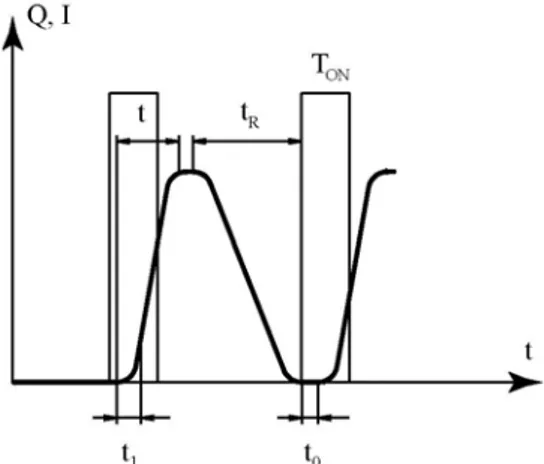
The dynamic behavior of the valve has been studied with tests based on on-off cycles with prefixed fre-quency values (fig. 8).
Fig. 7. Main signal time of current I and flow Q, where Ton
is the electrical activation time, tR is the global return time,
t1 is the activation time and t0 is the average dead time due
to the acquisition.
The valve output and the mass flow meter have been limited as more as possible, with a dead time t0
be-tween the electrical activation and the beginning of the wires contraction due to the gap between the valve and the point of measure of the instrument. Consequently, it is suitable to analyze also the activa-tion time t1, the response time t∞ and the plug return
time tR.
An activation with Icost = 500 mA and TON = 200
ms has been used to analyze the dynamic behavior of the valve, overworking the suggestions from the last tests: at the beginning, TOFF has been set at 800 ms
with a 1 Hz frequency, because a slow return of the plug was expected. Then the time TOFF has been
ad-justed till 450 ms, while the working frequency was 1.5 Hz and the duty cycle DC was almost 30%. The number of cycles is commanded by a variable resis-tance at 100 impulses of current: this value is compa-rable with other different scientific studies [13, 7, 9] that agree upon the noteworthy degradation of the SMA properties after hundred cycles.
The input pressure P1 has been set at 1.2 bar by
the digital regulator. Sometimes, the opening of the plug has resulted not complete; in fact its step has shown smaller amplitude, especially in the first ten cycles, then the on-off signal enters in the regime region.
Fig. 9. Some on-off cycles: the current signal (Icost equal to
500 mA, TON 200 ms e TOFF 450 ms) and the flow signal.
From experiments (fig. 9) has emerged that:
• the activation phase (the open of the plug) is re-peatable and substantially constant; in fact the main times are easily extracted, and the average dead time t0 is 100 ms, the activation time t1 and
the response time t∞ are the same of the time
ex-tracted with the response tests.
• the return of the wires is not repeatable and not linear in the first analyzed 100 cycles., because the cooling is a complex process: although the global return time tR is 450 ms, the way
Input parameters Dynamic response of the valve Icost 500 mA t0 100 ms TON 200 ms t1 15 ms TOFF 450 ms t∞ 80 ms DC 30 % tR 450 ms f 1.5 Hz
Tab. 2. Dynamic characteristics of the mesovalve during the test with an input pressure P1 of 1.2 bar
for 100 cycles.
Table 2 summarizes the values of the response times for the on-off cycle at a frequency of 1.5 Hz, shown in figure 9.
These tests have been performed with two different loads: a pure thermal one and a mechanical one. The former is due to the sum between the spring force and the pressure due to the input air flow, the latter to the phase changes from martensite to austenite and vice versa. If the shape memory alloy is subjected to a group of thermo-mechanical cycles, many proper-ties are influenced. From a metallurgic viewpoint, the fatigue degrades the material with the softening, while a more elastic behavior is noted when the valve is dismantled and reassembled. Using the wires with almost hundred cycles, some micro-cracks let the breaking very easy [8]. This effect is proportional to the quantity of the supplied energy, as a matter of fact these phenomena are as more intense are the TON
and I cost values; a deepened study of the fatigue
prob-lem shall be accounted to avoid or to delay this de-gradation.
VI C
ONCLUSIONSSeveral prototypes have been experimentally analyzed and a 80-100 ms response time with a 1.5 Hz frequency has been obtained with a 30% duty cycle. The electrical feeding for the activation of the NiTi wires has resulted almost 500 mA for 200 ms. The most important external parameters that influ-ence the cycle life are. time, temperature, stresses and application type, the deformations and the cycles number, while the biasing internal parameters are the alloy composition, the thermal and the mechanical treatments. The maximum “memory effect” is ob-tained after that the stresses and the limit deforma-tions have been selected in function of the working cycles number. In [14], some useful data are pre-sented to describe the fatigue of the shape memory alloy: this data should be used as a drive-line for the standard NiTi fibers. The alloy for the wires of the SMA valve shows better properties than the standard NiTi wires, and the Stoeckel values with a safety margin are used for this valve. Anyway, the wires
shall be always changed after 100 cycles, with no dependence on the applied load.
As the hysteresis is biased by a lot of parameters, the thermo-mechanical behavior results very com-plex. As a consequence, a relationship between the temperature and the displacement or between the temperature and the applied forces cannot be easily found.
Future developments can be obtain following to the same working principle [11, 13] but with varied design of the device, different shape memory actua-tors, improved feeding system or performance analysis instruments: i.e., among the different choices, a normally open valve or a valve with multi-ple outputs can be easily realized.
An opportune pressure P0 applied to the internal
surface of the plug could, for example, replace the spring force. This would favor the miniaturization of the valve. Even though the assemblability problem remains, the plug should be at least redesigned to estimate the inlet pressure effects. The absence of the spring would improve the manual assembly phase in the normally opened configuration: this design option is not yet implemented.
Fig. 10. The valve is 3/2 bistable passive.
In case of a normally -closed and -opened plug fixed at the SMA wires (Fig. 10) with the flow reaching the activation temperature Ta, the opening 1
will be closed and the opening 2 will be opened at the same time. The flow is then deviated and the valve remains in this stable configuration until the flow temperature decreases under Ta: the valve is therefore
3/2 bistable passive and it can be used as a safety valve to control the flow temperatures in those pas-sive safety systems as into chemical, petrol or also energy industries.
The valve can also be used as passive component without electrical activation of the wires to realize a safety valve associated to the reaching of a maximal temperature of the air flow.
R
EFERENCES[1] Belforte G., Manuale di pneumatica, Tecniche Nuove, Torino, Italy, 2005.
[2] S. Yokota, K. Yoshida, K. Bandoh, M. Suhara, Response of Proportional Valve using Shape Memory Alloy Array Actuators, pp. 77-82, Proc.
2nd International Symposium on Fluid Power
Transmission and Control ISFP, 1995.
[3] A.D.Johnson, J.D. Busch, Recent Pogress in the Application of Thin Film Shape Memory Alloy, pp.299-304, Proceedings of SMST 94, The First International Conference in Shape Memory and Superelastic Technologies, 7-10 March 1994, Pacific Grove, California, 1994.
[4] P. Krulevitch, A.P. Lee, P.B. Ramsey, J.C. Trevino, J. Hamilton, M.A. Northrup, Thin Film Shape Memory Alloy Microactuators, Journal of Microelectromechanical Systems, vo.5, n°4, pp. 270-282, December, 1996.
[5] Ferraresi C., Maffiodo D., Manuello Bertetto A, A novel pneumatic valve actuated by shape memory alloy wires, Int. Journal of Mechanics and Control, Torino, Vol. 02, n°01, npp. 49-56, ISSN 1590-8844.
[6] Maffiodo D., Sviluppo di attuatori innovativi a memoria di forma per applicazioni su compo-nenti meccanici, P.H.D. Thesis, Torino, … [7] Borboni A., Meso- to Micro- Actuators: A
Theo-retical and Practical Approach, CRC Press, New York, USA, 2008.
[8] Johnson A.D., Kraemer J. State of the Art of Shape Memory Actuators, Proc. 6th UK-Mechatronics Forum Int. Conf. (UK-Mechatronics ’98), 1998.
[9] Velazquez R., Hafez M., Szewczyk J., Pissaloux E. Experimental and Computational Ther-momechanical Study of a SMA Micro-Actuator: Aspect of Antagonist-Type Behaviour, 3rd MIT Conf. on Computational Fluid and Solid Mechanics, Boston, 2005.
[10] Borboni A. Microactuators, in Gad-el-Hak M. Editor, The MEMS Handbook, CRC Press, New York, USA, chapter 31, 2005.
[11] Ikuta K. Application of Shape Memory Alloy Actuator for Clean Gripper, Proc. 7th RO.MAN.SY Symp. Udine, Italy, 1998.
[12] Millman J., Grabel A. 1994. Microelectronics, Mc Graw-Hill.
[13] Leppäniemi A. 1998. Shape Memory Alloy: Ap-plications and Commercial Aspects, Proc. of th UK Mechatronics Forum Int. Conf. (Mechatronics ’98).
[14] Stoeckel D. 1992. Status and trends in shape memory technologiy, Proc. of Actuators 92, 3th International Conference on new actuators, Bremen, Germany.
[15] Ikuta K. 1990. Micro/Miniature shape memory alloy actuator, Proc. IEEE Workshop, 1990.
[16] Liu Y., Humbeek J.V., Stalmans R., Delaey L., 1997 Some aspects of the properties of the NiTi shape memory alloy, ELSEVIER, Jour-nal of alloy and compounds, 247 pp. 115-121. [17] Wu X.D., Fan Y.Z., Wu J.S. 2000. A study on
the variations of the electrical resistence for NiTi shape memory alloy during the thermo-mechanical loading, ELSEVIER, Materials and design, 21 pp. 511-515.
[18] Besselink P.A. 1996. Procedure for the calcula-tion of the geometry of a resistance heated NiTi- actuator, Proc. of Actuator 96, 5th Inter-national Conference on new actuators, Bremen, Germany.
[19] Potapov P.L. 1998. Thermoelectric triggering of phase transformation in Ni-Ti shape memory alloy, ELSEVIER, Materials science and engineering, B52 pp. 195-201.
[20] Ding Z., Lagoudas D.C. 1999. Transient heat transfer behaviourof one-dimensional symmetric thermo- electric SMA Actuators, PERGAMON, Mathematical and computer modelling, 29 pp. 33-55.
[21] Bekker A., Brinson L.C. 1997. Temperature-induced phase transformation in a shape memory alloy: phase diagram based kinetics approach, PERGAMON, J. Mech. Phys. sol-ids, Vol. 45 No 6 pp. 949-988.