UNIVERSITÀ DEGLI STUDI DI CATANIA “AGRICULTURAL, FOOD AND ENVIRONMENTAL SCIENCE”
XXIX CYCLE
DESIGN OF AN AUTOMATED SYSTEM FOR CONTINUOUS MONITORING
OF DAIRY COW BEHAVIOUR IN FREE-STALL BARNS
Massimo Mancino
Advisor: Prof. Claudia Arcidiacono Coordinator: Prof. Cherubino Leonardi
First of all, I would like to demonstrate my special acknowledgement to my wife Laura and our sons Mattia and Enrico for bearing my physical and mental absence. I could not have made my PhD studies without their support and understanding.
Also, I would like to thank my mother and my sister for their constant encouragements.
Moreover, it is a pleasure for me to write my gratitude to my Tutor and the research team of the section “Building and land engineering” of Di3A Department for helping and guiding me in their domains of expertise.
Finally, I would like to thank Mr. Vito Pavone who manages the farm “Agricola Alpa SS” in Ragusa (Sicily). He made available all his expertise to operate with the animals in the best way possible.
1 Abstract ... 6
2 Sommario... 8
3 Introduction ... 10
3.1 Preface ... 10
3.2 State of the art ... 12
3.2.1 Research studies on ICT applications to the analysis of livestock behaviour...12
3.2.2 The dairy cow's step counting through wearable sensors ...15
3.2.3 The feeding behavioural activity ...18
3.3 Objectives of the thesis work ... 23
3.4 Work organisation ... 25
4 Materials and methods ... 27
4.1 The data acquisition system ... 27
4.1.1 The wireless network ...29
4.1.2 The accelerometer sensor and the Texas Instruments SensorTag device ...32
4.1.3 The single-board computers and the Raspberry Pi ...34
4.1.4 The proposed data acquisition system ...35
4.2 The case study ... 40
4.2.1 The free-stall barn area under study ...40
4.2.2 The installation of the data acquisition system ...42
4.2.3 The validation system ...44
4.2.4 The walking analysis and the step counting ...46
4.2.5 The feeding classifier ...52
5 Results ... 59
5.1 The walking activity and the step counting ... 59
5.1.1 Data analysis through the modxy variable ...59
5.1.4 Sensitivity analysis ...64
5.2 The feeding activity ... 66
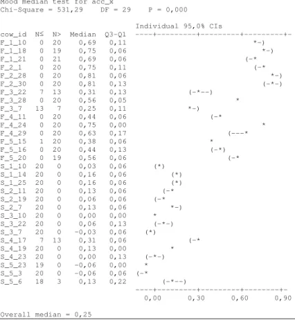
5.2.1 The data analysis through accx variable ...66
5.2.2 The data analysis through the frequency diagrams ...71
5.3 The design of the automated monitoring system ... 76
5.3.1 The data acquisition system ...77
5.3.2 The algorithm for behaviour recognition ...79
5.3.3 The overall design of the automated monitoring system ...81
5.4 Feasibility study on gyroscope and barometer sensors ... 84
5.4.1 The gyroscope data during cow’s walking activity ...84
5.4.2 The barometer data and the gyroscope data during cows’ feeding activity ...87
6 Discussion ... 94
6.1 The walking activity and the step counting ... 94
6.1.1 Memory and time complexity analysis of the algorithm ...94
6.1.2 Real-time application of the system ...95
6.1.3 Comparison with literature results ...96
6.2 The feeding activity ... 98
6.2.1 Behaviour misclassification ...98
6.2.2 Comparisons with the research studies in the field ...101
6.3 The automated system proposed ... 104
6.4 The gyroscope and the barometer sensors ... 109
7 Conclusions ... 111
-6 -
1
Abstract
Change in cows’ behaviours is one of the indicators useful to help identifying when animals become ill. The need to analyse a large number of animals at a time due to the increase in the herd dimension in intensive farming has led to the use of automated systems. Among automated systems, inertial sensor-based systems have been utilised to distinguish behavioural patterns in livestock animals.
In this field, the overall aim of this thesis work, which was inherent to the field of the Precision Livestock Farming, was to contribute to the improvement of the systems based on wearable sensors that are able to recognise the main behavioural activities (i.e., lying, standing, feeding, and walking) of dairy cows housed in a free-stall barn. This objective was achieved through different steps aimed at producing an advance in the state of the art.
A novel algorithm, characterised by a linear computational time, was implemented with the aim to improve real-time monitoring and analysis of walking behaviour of dairy cows. The algorithm computed the number of steps of each cow from accelerometer data by making use of statistically defined thresholds. Algorithm accuracy was carried out by computing total error (E equal to 9.5 %) and Relative Measurement Error (RME between 2.4% and 4.8%).
A new classifier was assessed to recognise the cow feeding and standing behavioural activities by using statistically defined thresholds computed from accelerometer data. The accuracy of the classification was assessed by computing of the Misclassification Rate (MR equal to 5.56%).
A new data acquisition system assessed in a free-stall barn allowed the acquisition of data from different sensor devices,
-7 -
with a sampling frequency of 4 Hz, during the animals’ daily routine. It required a simple installation into the building and it did not need any preliminary calibration. The performance of this system was assessed by computing a Stored Data Index (DSI) that resulted equal to 83%.
Finally, the overall design of an automated monitoring system based on wearable sensors was proposed.
-8 -
2
Sommario
L’alterazione del comportamento degli animali è uno degli indicatori utili per identificare l’insorgenza di malattie. La necessità di controllare un numero sempre maggiore di capi negli allevamenti intensivi ha portato all’utilizzo di sistemi automatizzati per il loro monitoraggio. Tra questi, i sistemi basati su sensori inerziali sono stati recentemente proposti per classificare i pattern comportamentali degli animali negli allevamenti.
In questo ambito, che è inerente al campo della Precision Livestock Farming, il lavoro svolto durante il Dottorato di ricerca e descritto nella presente tesi si propone di contribuire al miglioramento di tali sistemi per il riconoscimento delle attività di lying, standing, feeding e walking delle bovine da latte allevate in una stalla a stabulazione libera.
Sulla base di un’ampia analisi dello stato dell’arte, tale obiettivo è stato conseguito tramite la definizione di nuovi approcci di applicazione della ICT (Information and Communications Technology) alla zootecnia intensiva. In particolare, è stato realizzato un nuovo algoritmo, caratterizzato da un complessità computazionale lineare, che effettua il calcolo del numero di passi di ogni bovina dai dati di accelerazione, facendo uso di soglie definite statisticamente. L’accuratezza dell’algoritmo è stata valutata sulla base dell’errore totale, pari al 9.5%, e del Relative Measurement Error, compreso tra il 2.4% e il 4.8%.
Inoltre, è stato definito un nuovo classificatore per distinguere l’attività del feeding dallo standing, utilizzando soglie calcolate statisticamente dai dati accelerometrici.
-9 -
L’accuratezza della classificazione è stata valutata sulla base del Misclassification Rate, pari al 5.56%.
L’applicazione in stalla di un nuovo sistema di acquisizione dei dati ha permesso di migliorare la raccolta dei dati da differenti sensori durante la routine giornaliera degli animali. Il sistema proposto richiede un’installazione facilitata e non necessita di calibrazioni preliminari. La sua prestazione è stata valutata mediante lo Stored Data Index che è risultato pari all’83%.
Infine, viene proposto il progetto di un sistema complessivo per il monitoraggio in automatico dei comportamenti delle bovine basato su sensori indossabili.
-10 -
3
Introduction
3.1 Preface
In this century, public concern over industrial methods of rearing animals and their impact on farm animal welfare have increased (Miele and Lever, 2013). At the consumers’ level, there is a growing realisation of a link, direct or indirect, between animal welfare and food safety and quality (Rowbotham and Ruegg, 2015). Scientific research is also involved in assessing whether animal welfare could influence productivity (Coignard et al., 2014). This growing interest towards animal welfare in intensive farming, which is also diffuse among the stakeholders, has joined with other current arising problems related to livestock farming management. Among these, the increase of herd dimension that has reduced the farmer’s capability of visually controlling the animals and the need to decrease the livestock management expenditures due to the labour cost.
These issues have contributed to produce an increasingly spread and shared adoption of automated computational procedures for the analysis of animal behaviour.
Different kinds of innovative systems and automated tools have been proposed or assessed for the observation of animal behaviours. Among these, the automated visual recognition of cow's lying, standing, and walking behavioural activities by using a computer-vision based system (Mattachini et al., 2011; Mortensen et al., 2016; S. M. C. S. M. C. Porto et al., 2013; Song et al., 2008), the automated sound recognition (Ferrari et al., 2010; Fontana et al., 2015; Vandermeulen et al., 2016), the outdoor animal localisation by using Global Positioning Systems (Barbari et al., 2006; Godsk and
-11 -
Kjærgaard, 2015) and the in-door animal localisation by using Radio Frequency Identification tags (Barbari et al., 2013; Maselyne et al., 2016; Porto et al., 2012; Voulodimos et al., 2010) and Ultra-Wide Band tags (Ipema et al., 2013; Porto et al., 2014). Some drawbacks of these systems are their high cost and the need to have highly specialised operators to calibrate them when a modification of the system within the monitored areas of the breeding environment or an extension of the system are required.
Therefore, in recent times, innovative systems and automated computational procedures based on inertial wearable sensors have been adopted to provide effective and accurate monitoring and analysis of cow behaviour to improve animal’s health and welfare and respond to different issues related to the high cost of the systems, effectiveness of the outcomes, and completeness of the behaviours analysed. In these systems, the sensors attached to the animals are suitable to detect events or measure changes in some physical quantities (e.g., acceleration, pressure, air relative humidity, and air temperature).
Research studies on wearable sensor-based systems can be broadly categorised into two groups of works, which depend on the system proposed. It can be a commercial system or a prototype built by the research team. When a commercial system is tested, in the work there is usually no information on the algorithm due to patent rights, therefore researchers cannot contribute to its improvement and the work is mainly aimed at assessing the accuracy of the results compared to other systems considered as the ‘golden standard’. When a prototype of the system is proposed, the algorithm as well as software and hardware specifications are usually provided and this facilitates comparisons with other algorithms and the
-12 -
advance of the research in the field. With reference to wearable sensors, most of the studies in this field have been focused on hardware improvement (Darr and Epperson, 2009; Kumar and Hancke, 2015; Nadimi et al., 2012; Pastell et al., 2009), while few research studies have been conducted to improve algorithms and implement the related software (Alsaaod et al., 2015; Nielsen et al., 2010). Furthermore, there is the need to cope with the difficulties related to the conduction of a thorough analysis of all the monitored behavioural activities of the animal.
Therefore, challenges still exist in this field of research, in which the thesis work was developed and aimed at contributing to the increase of knowledge.
On this basis, in the following Sections, an extensive analysis of literature is carried out (Section 3.2) to investigate the state of the art, which constitutes the knowledge base of this thesis work, and subsequently the objectives of the thesis work (Section 3.3) are described with reference to the highlighted issues in the field.
3.2 State of the art
3.2.1 Research studies on ICT applications to the analysis of livestock behaviour
In past times, animal observations were carried out by skilled operators either directly within the breeding environment by filling in a checklist, or by the visual analysis of images acquired from video-recording systems. Certainly, when these tasks are performed in a continuously way for a long time they became costly and time consuming (Alsaaod et al., 2015; Chanvallon et al., 2014; Nielsen et al., 2010; Robert et al., 2009). For these reasons, in the literature, these
-13 -
techniques of animal observation are often used only as the ‘golden standard’ for the validation of automated monitoring system of animal behaviours.
A type of automated monitoring system regards the
automated visual recognition of animal behaviours (Cangar
et al., 2008; Mattachini et al., 2011; Mortensen et al., 2016; Porto et al., 2013; Song et al., 2008).
In this field, a computer vision-based system (CVBS) was used and validated in two research studies (Porto et al., 2013; Porto et al., 2015) concerning the automated classification of cow's lying, standing, and feeding activities. The authors demonstrated the suitability of the Viola-Jones algorithm for image discrimination of the cow’s shape from the floor background. The proposed system based on automated image recognition required an accurate calibration phase of both the cameras and the algorithms that process the digital images. This required activity increases the complexity of the installation in the free-stall barn and the maintenance of the system when the farmer adopts any change in the observed breeding area.
Another type of automated system, which analyse health status of animals from activities other than behaviours, used
automated sound recognition to predict the chicken’s growth
(Fontana et al., 2015), the monitoring of pig’s cough (Guarino et al., 2008) or cow’s coughing frequency to recognise Bovine Respiratory Disease (Ferrari et al., 2010; Vandermeulen et al., 2016).
These kinds of monitoring systems do not allow the identification of each animal.
Other automated systems for the monitoring of livestock animals allows for both identification and localisation of each
-14 -
animal in the breeding environment and the recognition of its behaviours.
When the cows are at pasture or during outdoor activities (e.g., transport), Global Positioning Systems (GPSs) enable continuous and automatic tracking of an animal’s position (Barbari et al., 2006; Ungar et al., 2005) and an accurate recognition of cow's activities (Godsk and Kjærgaard, 2015). However, GPSs are not easily applicable indoor due to signal weakening. Therefore, other kinds of monitoring systems have been proposed in the last decades such as those based on radio frequency identification (RFID) technology. They make use of two main electronic components (tags and readers) that exchange information through radio waves. Among automated systems based on RFID technology, those based on ultra-wide band (UWB) technology can identify and locate animal inside the livestock buildings with a higher accuracy then those based on high frequency (HF) and ultra-high frequency (UHF) technologies (Ilie-Zudor et al., 2011; Ipema et al., 2013; Porto et al., 2014, 2012). Although these types of monitoring systems make it possible to track each animal of the herd, they have a high cost that is not always sustainable for farmers. Moreover, their setting up within the breeding environment is often complex in relation to the layout and building characteristics of the barn to be monitored.
Recently, other monitoring systems based on wearable
sensors have been more and more widely utilised due to their
low cost and easy integration with other ICT devices (e.g., computers and wireless networks). These sensors are able to measure difference in physical quantity (e.g., acceleration, pressure, air temperature, and air relative humidity). For instance, accelerometer sensors implemented in smart
-15 -
devices were used to monitor human behaviour and health (Mathie et al., 2004). Later, in a pilot study, they were also applied to livestock (Martiskainen et al., 2009) in order to classify dairy cow's behavioural activities by using a Support
Vector Machine (SVM).
In literature, the classification of standing and lying was already successfully assessed by using an accelerometer fixed to the cow’s leg (Arcidiacono et al., 2015; Darr and Epperson, 2009). In fact, an acceleration threshold value equal to 0.5 g was found suitable to recognise standing from lying. Different systems to recognise walking and feeding are still currently under study, and their features will be described in the following sub-sections.
3.2.2 The dairy cow's step counting through wearable sensors
Concerning the monitoring of walking behaviour of dairy cows within free-stall barns, the most frequently adopted wearable sensor is the accelerometer. The pedometer attached to cow’s leg is the most used device that is equipped with an accelerometer. It provides a valuable and complete information (e.g., activity indices and step counting) about the periods spent by the animal in ‘rest’ and in ‘restless’ activities during its daily routine.
It is well know that this information is relevant for early detection of oestrous in dairy cows (Chanvallon et al., 2014; Firk et al., 2002; Silper et al., 2015) as well as for lameness (Alsaaod et al., 2012; Mazrier et al., 2006). However, the analysis of walking activity by using pedometers needs refinement to improve the accuracy of the step count and obtain its real-time acquisition. Actually, the information provided by pedometers is not available in real time, because
-16 -
the pedometer data is downloaded by the monitoring system only during the milking process (e.g., twice a day). Due to the current widespread use of pedometers, any technical improvement would be valuable for farmers and could be a significant step forward in the enhancement of systems based on wearable sensors.
In this field, there has been an increased focus on real-time cow's step counting. However, technical specifications of this kind of systems as well as the code of the step counting algorithm are seldom included in the literature.
The IceTag3DTM (IceRobotics Ltd, Edinburgh, UK) is a new
device which is based on three-dimensional acceleration technology (Figure 1).
Figure 1. The IceTag3D pedometer.
It works at a sampling frequency of 16 Hz (Kokin et al., 2014). This device was validated by Nielsen et al. (2010) and it provided information at 1-second intervals about the posture of a cow (standing vs. lying), whether the leg to which the sensor is attached was moving or not, and the
-17 -
number of steps taken per time unit. The aim of their study was to develop an algorithm for predicting the duration of walking and standing periods based on a moving average of the output from the IceTag3DTM device. Moreover, the step
count and lying/standing prediction of the IceTag3DTM
device were also validated against video recordings. The authors reported that accurate results were achieved from their experiments conducted on 10 cows, yet since the IceTag3DTM is a commercial product supplied with a
proprietary software, no information about the step counting algorithm was found.
Likewise, in a new version of the algorithm of RumiWatch pedometer (ITIN+HOCH GmbH, Fütterungstechnik, Liestal, Switzerland), proposed by Alsaaod et al. (2015), the authors provided no information about the code of the algorithm, whereas the outcomes of the application of the proposed algorithm on 21 cows were reported in detail as well as other technical features of RumiWatch pedometer (Figure 2). Among these, the sampling frequency of the accelerometer for monitoring walking behaviour, which was equal to 10 Hz, was considered very high by the authors.
-18 - Figure 2. The RumiWatch pedometer.
3.2.3 The feeding behavioural activity
According to one of the principles of animal welfare, 'good feeding' improves animal's comfort and well-being and indicates whether a management system is well designed or not (Burow et al., 2011; Grant and Albright, 2000; Praks et al., 2011). Since changes in feeding behavioural activity are increasingly recognised as a useful indicator of cow's health and welfare, the monitoring of changes in feeding activity may be useful in early detection and prevention of diseases. The observation of feeding behaviour of animals is usually carried out directly by operators within the breeding environment or by the visual analysis of images acquired from video-recording systems. Since these two monitoring systems are usually costly and time consuming when they are
-19 -
not automated (Abdanan Mehdizadeh et al., 2015; Berckmans, 2004), other kinds of systems, such as those based on radio frequency identification (RFID) technology, have been proposed in the last decades. They utilise transponder tags that identify each animal individually and localise it during the feeding activity (e.g., during the visit at the feeding alley). Among automated systems based on RFID technology, a higher accuracy is achieved by those based on ultra-wide band (UWB) technology compared to those based on high frequency (HF) and ultra-high frequency (UHF) technologies (Frondelius et al., 2015; Ipema et al., 2013; Porto et al., 2014, 2012; Schwartzkopf-Genswein et al., 1999; Tullo et al., 2016). The main disadvantages of the application of these systems are their high cost, which is not always sustainable for farmers, as well as the complex setting up in relation to the layout and building characteristics of the barn. Feeding behaviour is studied also during the animal outdoor activities by using Global Positioning Systems (GPSs) that enable continuous and automatic tracking of an animal’s position (Ungar et al., 2005) and an accurate recognition of cow's activities (Godsk and Kjærgaard, 2015). However, GPSs are not easily applicable for the indoor analysis of feeding behaviour due to signal weakening.
Recently, other monitoring systems based on wearable sensors are being utilised more and more widely due to their low cost and easy integration with other ICT devices (e.g., computers and wireless networks). Wearable sensors are suitable for detecting events related to animals (e.g., change in acceleration, change in angular velocity, and change in sound waves or pressure due to chewing activity) or changes in the microclimate of the animal occupied zone (e.g., air
-20 -
temperature and relative humidity, and atmospheric pressure).
With regard to the analysis of feeding behaviour of dairy cows, the most used wearable sensors are pressure sensors and accelerometers.
With reference to pressure sensors, in two experimental tests that were carried out by Ruuska et al. (2015) dairy cows were equipped with a RumiWatch noseband sensor (Figure 3).
Figure 3. RumiWatch noseband sensor.
The data acquired by the sensor were compared with those obtained by two other monitoring systems, i.e., a system for continuous recording of cow's behaviours (Experimental test 1) and a system suitable for the control of the visits to the automated feeders (Experimental test 2). In these tests the output of the RumiWatch algorithm was assessed, however
-21 -
no information was provided about its features. Moreover, since the pressure sensor was placed in the noseband of the halter, the system was more invasive than other wearable sensors.
As concerns accelerometer-based systems, Martiskainen et al. (2009) carried out data acquisition from an accelerometer fixed to the collar of 30 cows in order to classify their behavioural activities by using a Support Vector Machine (SVM). However, the use of the SVM requires a training phase to reach a high level of accuracy in behaviour recognition.
In a later study, other researchers (Ueda et al., 2011) utilised a uniaxial accelerometer, named Kenz Lifecorder Ex (LCEX; Suzuken Co. Ltd., Nagoya, Japan), which was fixed to the collar of 8 Holstein dairy cows in a grazing production system. The feeding behavioural activity was studied by using the intensity of the movement recorded by the device in order to determine the eating time (min/d) that is one of the factors, together with biting rate (bite/min) and bite mass (g of DM/bite), utilised to compute DMI (Dry Matter Intake). In a recent study, Delagarde & Lamberton (2015) assessed the Plus version of the Lifecorder device (Figure 4) by fixing it to the collar of six cows in order to measure the following activities: grazing, ruminating and so-called ‘other activities’, i.e., drinking, walking without biting or searching, resting, and social interaction.
-22 -
Figure 4. Lifecorder Plus activity monitor.
However, no information was provided about the features of the algorithm and no accelerometer data were available in both studies (Delagarde and Lamberton, 2015; Ueda et al., 2011).
Differently from these studies, Oudshoorn et al. (2013) reported the accelerometer data related to cow's feeding behavioural activity. In detail, an accelerometer device combined with bite count was proposed to evaluate the grass intake of dairy cow at pasture. Acceleration threshold values during feeding activity were defined. However, these outcomes were related to grazing cows, which show different postures during feeding activity compared to cows bred inside a barn.
According to several researchers, in the near future accelerometers are the most ‘promising’ sensors among the devices studied in the literature because they are commercially available and low-cost products. However, there is still work to be done in this field in order to design models and systems that fully comply with Precision Livestock Farming (PLF) principles (Berckmans, 2004) and
-23 -
are suitable for discriminating all the animal’s behavioural activities with a good accuracy.
Accelerometer-based monitoring systems that utilise acceleration threshold values to study feeding behaviour are valuable because they have several advantages. Among them, they do not require a training phase as for SVM-based systems, they are not invasive for the animal if the sensor is applied to the collar and, finally, once the thresholds values are determined the computational cost of the classifier for automated monitoring is lower. Until now, acceleration threshold values during the feeding activity have been defined only for grazing cows (Oudshoorn et al., 2013).
3.3 Objectives of the thesis work
The main objective of this study was to contribute to the improvement of the scientific knowledge in the field of ICT applications to livestock farming, which is essential to deal with the issues and challenges highlighted in the preface (Section 3.1). To this aim, this thesis work involved the design of an effective automated system suitable for the recognition of the main dairy cows’ behavioural activities, i.e., lying, standing, walking, and feeding. This objective (objective 1) is a relevant aspect of the Precision Livestock
Farming (PLF), which offers the possibility to achieve
economically, environmentally and socially sustainable farming through continuous automatic observation, real time data interpretation and active control on the smallest possible group of animals (Berckmans, 2011).
The proposed automated system was not based on any commercial ready-to-use product specifically designed for PLF application. In fact, the hardware components were
-24 -
general-purpose devices and all high-level software needed for data acquisition and data elaboration was developed using open source operating system and software library that are free available on the Web.
Following this approach, a module of the proposed system was constituted by a new data acquisition system (DAS) based on low-cost technology and open-source software. Since DAS was designed and implemented taking into account the complexity of structural components, materials, and layout of functional areas of a free-stall barn, it guaranteed a simplified installation into the breeding environment. Two main elements, the sensors and the receiver, interconnected by a wireless network, composed it and they did not require any calibration or other preliminary operation before or during the registration process.
With regard to cow's standing and lying behaviours, the literature concerning the recognition of these behaviours by using wearable sensors fixed to dairy cows’ body is already well-established. On the contrary, different methods and systems aimed at recognising walking and feeding behaviours are still currently under study. Undoubtedly, these two behavioural activities are relevant for detecting some specific state (oestrous and lameness) of the animal and its interaction with the barn building and the feeding management system. For instance, the increasing in walking activity when cows are in oestrus was reported in some studies (Firk et al., 2002; Chanvallon et al., 2014). Other researchers (DeVries et al., 2003; DeVries and von Keyserlingk, 2006) studied different typologies of feeding management system to improve building characteristics of the barn. Since thermal comfort of the animals would also have an effect on their behaviours,
-25 -
research on the use of new sustainable materials would be valuable (Barreca and Fichera, 2013a, 2013b).
With the aim of achieving an advance in the state of the art, a relevant part of my research was dedicated to the study of cows’ walking behaviour in a free-stall barn. This analysis allowed the development and the implementation of an open-source step-counting algorithm based on acceleration thresholds, which were statistically determined (objective 2). Moreover, the systematic study of cows’ feeding behaviour in a free-stall barn was conducted. This knowledge made it possible to define acceleration thresholds suitable for the automated discrimination of cows’ feeding activities from standing ones (objective 3).
Finally, during the activities developed in my study, further results were achieved:
− The performance of the sensor devices was improved by using a new version of the firmware.
− The data retrieved by gyroscope sensors and the accelerometer sensors, during cows’ walking activities, was analysed and compared.
− The data retrieved by gyroscope, barometer, and accelerometer sensors, during the cows’ feeding activities, was analysed and compared.
3.4 Work organisation
The materials and methods used to achieve the animal behaviour detection are reported in Section 3 of this thesis. The whole sub-section 4.1 contains detailed information and specifications of the new data acquisition system, while the case study is presented in Section 4.2.
-26 -
Section 5 focuses on the results achieved by the novel step-counting algorithm (sub-section 5.1) and the new classifier for the feeding and standing activities (sub-section 5.2). These subsections are followed by the overall design of the automated monitoring system (Section 5.3) and the results of a feasibility study on the gyroscope and barometer sensors (Section 5.4).
In Section 6, the results are discussed and compared with other studies in the literature. Moreover, considerations on new improvements for future work are also reported.
In the field of PLF, the advance in the state of the art achieved in this PhD study is highlighted in Section 7.
-27 -
4
Materials and methods
4.1 The data acquisition system
A period of my PhD work was devoted to the analysis of the most up-to-date data acquisition systems (DAS), specifically on data retrieving from sensors, which are embedded in last-generation MEMS (Micro Electro-Mechanical Systems) devices. It is well known that a data acquisition system, which is capable of converting the measure of a physical variable acquired by a sensor into the related numerical value in digital format, is implemented within MEMS smart devices and thus it provides data ready to be elaborated. Differently from this kind of embedded data acquisition system, in this study the term DAS refers to an high-level ICT-based system designed to be installed in a barn and equipped with modules that allow simultaneous connections between the different wearable devices, fixed on animal's body, and a unit for data control and storage. The modules that compose the system are the sensors, a communication channel, and the unit for data control and storage.
In this phase of my PhD activity, the analysis was focused on the features of the most recent ICT technologies and on their integration, particularly taking into account the following aspects:
− How it is invasive for cows, in view of ‘avoiding
animal stress’.
− Costs of hardware and software components.
− Ease of installation in relation to the building characteristics of the barn.
− Ease of interaction with the software. − Possibility to remote control the system.
-28 -
− Reduction of the periods of disconnection, which cause data loss.
− Portability of the data files between different software applications.
− Consistency and usability of data, i.e., using and showing data in different ways without changing the structure.
− Storage of log files related to the events occurred during data acquisition.
− System scalability, to improve the performance of the system, when the monitoring of a higher number of animals is required or the increasing of the surface of the monitored area is needed.
With regard to the communication between the devices fixed to the cow's body and the unit for data control and storage,
Wireless Sensor Networks (WSN), which are currently and
widely considered in several studies (Huircán et al., 2010; Kwong et al., 2012; Nadimi et al., 2012) were utilised in the experiments. This choice made it possible to reduce the invasive aspect of the system for the animals and simplified the system installation in the barn, still allowing for continuous acquisition of the data in real time. With reference to sensors, low-cost MEMS smart devices were selected. They are equipped with various sensors (accelerometer, gyroscope, magnetometer, thermometer, barometer, and hygrometer), a control unit for the internal memory management and data communication, and a module for the wireless connection. Finally, the unit for data control and storage was made of a single board computer that was suitably configured and programmed by using the Phyton
-29 -
language in order to handle the connections with the smart devices and store the data on a non-volatile memory.
4.1.1 The wireless network
The wireless networks are classified according to various topologies. Depending on the distance to be achieved (extension of the network), the categories are the following:
− Wireless Personal Area Network (WPAN), which has a short range (7 – 10 meters) and connects two or a few devices with low power consumption (IEEE 802.15.x standards).
− Wireless Local Area Network (WLAN), which consumes more power yet extends the connection to about 100 meters in the same building (IEEE 802.11x standards).
− Wireless Metropolitan Area Network (WMAN), which extends the range to a larger geographic area, such as a city or suburb.
− Wireless Wide Area Network (WWAN), which
provides connectivity over a wide geographical area. Usually WWANs are networks used for mobile phone and data service and are operated by carriers.
Since my field of study was focused on the monitoring of cows in a restricted area, which is the area of a free-stall barn, my interest was focused on WLAN and WPAN categories. In the WLAN field, the standard adopted from IEEE (Institute
of Electrical and Electronic Engineers) is 802.11 and the
term commonly used is WiFi network. The wireless networks (802.11, 802.11a, 802.11b, 802.11g and 802.11n) typically have a frequency of 2.4 GHz and the stream data rate is from 1-2 Mbit/s to 600 Mbit/s.
-30 -
A sub-type of wireless connection is the WPAN, in which two or more devices are interconnected using a low-power wireless technology within a range of about 10 meters. The most commonly used WPAN networks are Infrared Data
Association (IrDA), ZigBee, and Bluetooth low energy (BLE
or Bluetooth Smart).
The IrDA protocol requires the so-called Line of Sight (LoS), i.e., the devices have to be in mutual visibility, and within a distance of few meters. Therefore, the IrDA network was not kept into consideration in my research activity.
ZigBee is a wireless mesh network of low-cost and low-power
nodes, developed to increase the battery life of the devices. Since each node of a network with a mesh topology is able to carry data for the network, the devices can transmit data over a long distance, from 10 to 100 m, and the availability of the network is assured because it can reconfigure itself around broken paths. Zigbee belongs to IEEE 802.15 class family and, typically, its radio bands is of 2.4 GHz with a data transfer rate from 20 Kbit/s to 250 Kbit/s. All these features and its low latency make the ZigBee network a good choice for monitoring applications. Unfortunately, during my PhD it was not possible to find accelerometer sensors implemented into a ZigBee smart device.
BLE is a technology designed and marked by the Bluetooth Special Interest Group aimed at novel applications in the
healthcare, fitness, beacons, security, and home entertainment industries. Compared to ‘classic’ Bluetooth,
BLE is intended to provide considerably reduced power
consumption and cost while maintaining a similar communication range.
BLE is more efficient for transferring very small quantities of
-31 -
that are transferred at 1 Mbps. These and more features make
BLE a great option for applications where the maximum bit
rate is of just a few hundred bits-per-second, or less.
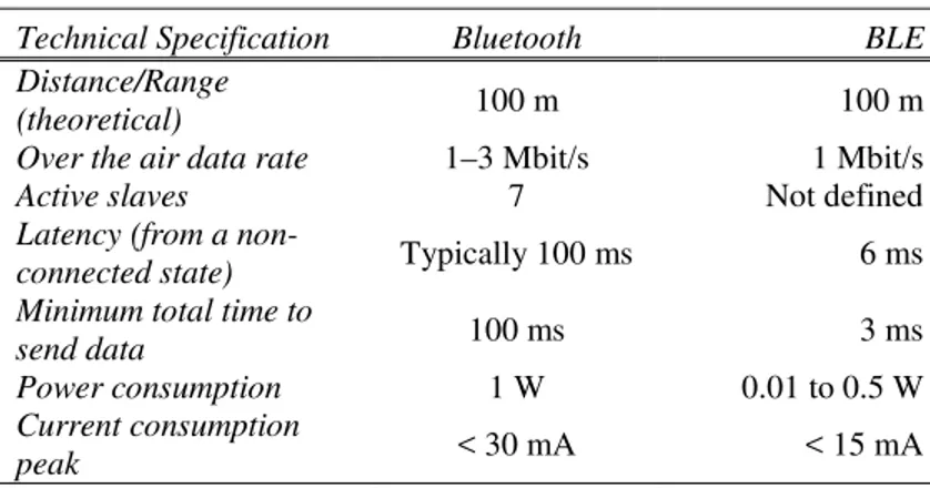
In Table 1, a comparison between the most relevant features of ‘classic’ Bluetooth and BLE is reported.
Table 1. A comparison between 'Classic' Bluetooth and BLE.
Technical Specification Bluetooth BLE
Distance/Range
(theoretical) 100 m 100 m
Over the air data rate 1–3 Mbit/s 1 Mbit/s
Active slaves 7 Not defined
Latency (from a
non-connected state) Typically 100 ms 6 ms
Minimum total time to
send data 100 ms 3 ms
Power consumption 1 W 0.01 to 0.5 W
Current consumption
peak < 30 mA < 15 mA
The total time of sending data is generally less than 6 ms, and as low as 3 ms (compared to 100 ms with ‘classic’ Bluetooth). This enables an application to form a connection and send data for a short communication burst before quickly tearing down the connection.
Thanks to an increased modulation index, BLE technology offers a somewhat improved range with respect to ‘classic’ Bluetooth, theoretically up to 200 feet (60 m) and beyond. However, the technology is still suited for mainly small-range applications. Usually, in fact, the range of the BLE is used with the typical 30-foot (10 m) range of ‘classic’ Bluetooth.
-32 -
4.1.2 The accelerometer sensor and the Texas Instruments SensorTag device
An accelerometer is an electromechanical device that measures acceleration forces. These forces may be static, like the constant force of gravity, or they could be dynamic, caused by moving or vibrating the accelerometer. The accelerometer measures the acceleration force in meters per squared second (m/s2) or in G-forces (g).
There are different types of accelerometer. One of these utilises the piezoelectric effect, i.e., a microscopic crystal structures built in the sensor that get stressed by accelerative force and this causes the production of a voltage.
Another type is able to sense changes in capacitance (i.e., the ability of a body to store an electrical charge). In this case, the device contains two microstructures next to each other and they have a certain capacitance between them. When an accelerative force moves one of the structures, then the capacitance will change. A circuitry, which converts from capacitance to voltage, is needed to get a measurement of the acceleration.
An accelerometer with a piezoresistive effect uses a semiconductor or a metal that is able to change its electrical resistivity when a mechanical force is applied.
Technologically advanced methods are based on the detection of temperature variations due to convective heat exchange. They utilise an 'activation current' in the device to produce the development of small hot air bubbles. The application of a force along the accelerometer axis causes the bubble movement and the subsequent temperature variation, which is detected by the sensors. This temperature variation is transformed into an acceleration variation.
-33 -
The advantages of these kind of sensors are compactness, weight, sensitivity to small acceleration, and low cost of construction.
The development of the technology of microscopic devices, which contains moving parts, is increasing more and more. Nowadays, Microelectromechanical systems (MEMS) and
Nanoelectromechanical systems (NEMS) are the most used
devices in this field.
Texas Instruments produces a specific MEMS device, named SensorTag, that includes several sensing unit for: air relative
humidity, pressure, position/motion and air temperature. Table 2 shows an overview of its hardware.
Table 2. SensorTag hardware overview.
Component Supplier
TMP006 Contactless IR Temperature Sensor Texas Instruments
SHT21 Humidity Sensor Sensirion
IMU-3000 Gyroscope Invensense
KXTJ9 Accelerometer Kionix
MAG3110 Magnetometer Freescale
T5400(C953H) Barometric Pressure Sensor Epcos CC2541 Bluetooth Low Energy Radio SoC Texas Instruments TPS62730 Ultra Low Power DC/DC
Converter Texas Instruments
The data measured from each sensor unit can be sampled to different rates and it can be send via BLE to a receiver. Acceleration sensing is based on the principle of a differential in capacitance. The SensorTag has not a built-in memory unit, so it is not able to store data permanently. Moreover, to save battery live it has the ‘sleep mode’ activated in its firmware, i.e., after 180 seconds, without any exchange of data, the SensorTag is disconnected from the master device
-34 -
and it is impossible to get a new connection without switching on the device by using its button. To avoid this type of disconnections, a new update firmware was uploaded and installed on each device.
4.1.3 The single-board computers and the Raspberry Pi
A control component, which was able to handle the acquisition process as well as to store consistent data from SensorTag devices, was needed and at this regard the single-board computers were an excellent choice. A single-single-board
computer (SBC) is a complete computer built on a single
circuit board, with microprocessor(s), memory and input/output interfaces. A SBC reduces the system’s overall cost, by reducing the number of circuit boards required. Moreover, it eliminates the problems due two connectors, since they are source of reliability problems.
The installation of a SBC in a free-stall barn is simplified and facilitated, because it has a low volume compared to a standard PC and its protection with a robust case is easily carried out when utilised in a hostile environment. Moreover, the installation requires only one cable, i.e., the power cable. The SBC adopted in the proposed data acquisition system was the Raspberry Pi 1 Model B (Raspberry Pi Foundation, UK). The Table 3 shows the hardware features of the Raspberry Pi Model B.
-35 - Table 3. Raspberry Pi hardware features.
Component Description
SOC Broadcom BCM2835
CPU 700 MHz single-core ARM1176JZF-S
GPU
Broadcom VideoCore IV OpenGL ES 2.0 1080p30 H.264 high-profile decoder and encoder
Memory 512 MB
Number of
USB Ports 2
Video input 15-pin connector MIPI Camera Interface (CSI)
Video output RCA connector HDMI
Audio input I²S serial bus
Audio output 3.5 mm Jack HDMI
Network Ethernet 10/100 Mbit/s
Current
(Absorbed power) 700 mA (3.5 W)
Power supply 5 V via MicroUSB
The Raspberry Pi was equipped with the following software: Raspbian Operating System and Python v2.7.6. The BLUEZ v5.4 libraries and the Pexpect v3.3 Python module were subsequently added. This software stack was needed to run the Python software module that managed the BLE connection as specified in the following of the text.
4.1.4 The proposed data acquisition system
In the literature, it is widely acknowledged that the continuous monitoring of each animal is a fundamental issue in the field of PLF. To achieve this aim, a robust data
acquisition system (DAS) was required; it acquired the data
-36 -
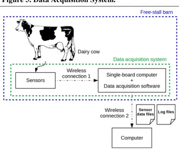
dairy cows bred in the free-stall barn. The Figure 5 shows the proposed data acquisition system.
Figure 5. Data Acquisition System.
To implement this system, Texas Instruments SensorTags were used as wearable sensors attached to cow’s body (e.g., leg and neck). Each SensorTag has a unique ID number that is used to distinguish each dairy cow during the data acquisition process and the next phase of the data analysis. Since these sensor devices have not a memory unit, they are not able to store the acquired data. Therefore, a second component is needed, i.e., a control unit that manages connections to the devices and stores consistent data into a memory storage unit by using files. Since the free-stall barn is a ‘hostile’ environment for the electronic devices, the SBC
Rasberry Pi was considered in the design and in the
-37 -
The ‘Wireless Connection 1’ of Figure 5 was achieved by BLE wireless connections because a BLE communication module was provided in both Raspberry Pi and TI SensorTags.
Finally, the ‘Wireless Connection 2’ was implemented by using the WiFi-USB adapter installed on the Raspberry Pi. When used with a desktop computer, this wireless connection allowed the following tasks:
− The managing of the Raspberry Pi, i.e., login, logout, restart, and shutdown;
− The managing of the data acquisition process, i.e., start, stop, and monitoring of disconnected sensors; − The downloading of the data files (.cvs text file); − The downloading of the log files (.txt text file). The software module of the data acquisition system was developed using the Python programming language. This module, named PLFRecorder, had the following purposes:
− establish and maintain BLE connections to SensorTag devices;
− retrieve data from sensors;
− store the received data in consistent file (.csv format);
− attempt to re-establish BLE connections to disconnected SensorTag devices;
− store every occurred event, for each SensorTag device, in a log file.
The software module was composed by the following Python scripts:
− settings.xml; − sensor_calcs.py;
-38 - − PLFRecorderSensorTag.py; − PLFRecorderStart.py; − PLFRecorderStop.py; − PLFRecorderDisconnectedSensors.py; − PLFRecorderShared.py.
The XML (eXtensible Markup Language) file named settings.xml contained all the parameters needed by the
PLFRecorder module to work correctly. A set of these
parameters was, for instance, the duration of the registration (the number of seconds or an indefinite time option), the sample rate of the measurements, the list of all the activated SensorTag devices during the registration and identified by a
MAC address (Media Access Control address), and, the
sensors to be activated for each SensorTag.
The Python file sensor_calcs.py was a utility library that performed low-level computation and numeric conversion. It was freely available on the Internet (https://github.com/mvartani76/RPi-Ble-Sensor-Tag-Python/blob/master/sensor_calcs.py).
PLFRecorderSettings.py is a utility script that reads the raw parameters from the file settings.xml and stores their values into well-defined variables, which are reusable by the other Python scripts.
The PLFRecorderSensorTag.py was the middle component of this software module. Its aim was to be an interface between low-level tasks (e.g., contained in sensor_calcs.py) and the high-level script that controls the registration process.
The file PLFRecorderStart.py, was the high-level main script. It runs the preliminary tasks, i.e., reading preference files, initialising global variables, and allocating memory
-39 -
working area. Then, it starts to establish connections with the SensorTag devices. It managed a list of the disconnected SensorTag using a queue. In computer science, a queue is a particular kind of abstract data type with a linear structure where a FIFO (First In First Out) criterion is adopted. At the beginning (first), all of the SensorTags were registered in the disconnected queue. When a connection was established, the respective SensorTag was pulled out from the queue and the process started to register the data coming from the device. If a connection between the Raspberry Pi and a SensorTag was lost, the process put the SensorTag in the disconnected queue. During the registration process, a thread tried continuously to empty the disconnected sensor queue.
Finally, three auxiliary scripts, named PLFRecorderStop.py,
PLFRecorderDisconnectedSensors.py, and PLFRecorderShared.py, were considered. The first script was useful when it was necessary to stop the registration before the established time or stop a registration that started with an indefinite time. When invoked, the second script wrote the list of the disconnected sensors in a text file. The file PLFRecorderShared.py contained shared code such as the definitions of the global variables as well as the global procedures used in the others scripts.
The performance of the DAS was computed by using the total quantity of data stored in the SD Card of the single board computer at the end of the acquisition process. This criterion was expressed by the indicator:
-40 -
where sdi is the amount of stored data during the data acquisition process by the i-th SensorTag and TSD is the
Theoretical Storeable Data, which is the maximum amount
of data that DAS can acquire during the time interval of the acquisition process. A SDI (Stored Data Index) equal to 100% means that no disconnection and neither system latencies nor system delays occurred during the process.
4.2 The case study
4.2.1 The free-stall barn area under study
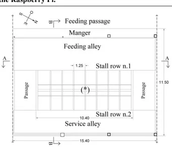
The experiments were carried out during June 2015 and June-July 2016 in a free-stall barn for dairy cow housing located in Sicily, in the territory of the municipality of Vittoria (province of Ragusa), at 234 m.a.s.l. The main building of the barn is 55.75 m long and 21.40 m wide (Figure 6) and it is completely open on three sides. Only the south-western front of the building is made of a load bearing masonry wall. The building is asymmetric with respect to the feeding passage from a point of view of both geometry and functionality of the breeding areas.
-41 - Figure 6. The plan of the free-stall barn.
The area north-east of the feeding passage has an overall width of 10.16 m and includes the resting area, the feeding alley, and a service alley. During the experiment, this area housed 53 Holstein dairy cows. The area south-west of the feeding passage has an overall width of 6.71 m and includes five multiple pens for calves' and steers' fattening by age, a room for farming tools storage, a space subdivided into two rooms, i.e., an office and a WC, and a convex-shaped manger adjacent to the feeding passage.
The barn is equipped with two different air-cooling systems, i.e., an evaporative one and a shower type with fans. The feed is supplied once a day by a mixer-wagon at about 6:30 a.m., and, during the day, feed that poured out is moved into the manger. Milking is carried out twice a day at 6:00 a.m. and 5:00 p.m., with three shifts and an overall milking duration of about two hours. The cleaning of the feeding and the service alleys is performed once a day by a scraper. The manure is stored in a manure-pit located outside the barn in front of the south side.
-42 -
Within the barn there were three groups of cows that were composed of 20 cows, 14 cows, and 19 cows. In this study, the second group of 14 cows, which were bred in the central pen of the barn, was selected (Figure 6).
4.2.2 The installation of the data acquisition system
The activity described in this sub-section was included in the thesis work to demonstrate how easy is the installation of the proposed acquisition system in free-stall barns. Figure 7 shows the area of interest, where the experimental trials were conducted.
Figure 7. Plan of the study area (*) and the position of the Raspberry Pi.
The Raspberry Pi was installed at the centre of the study area, fixed to a 2.5 m-high stake (see (*) on Figure 7). A power cable was fixed to the beams of the bearing structure of the
-43 -
barn. It started from the office within the free-stall barn to the Raspberry PI position. Since the Raspberry Pi was equipped with a WiFi-USB adaptor, other cables were not needed to establish a network connection with it.
In Figure 8 the Raspberry Pi setting is reported.
Figure 8. The Raspberry Pi position.
The computer located in the office of the barn, which was used as a module of the validation system (See Section 3.2.3), was equipped with the ‘Bitvise SSH Client’ free software. This software provides a free SSH (Secure Shell) client, able to establish a connection, between the computer in the office and the Raspberry Pi situated in the centre of the area of interest. This connection was utilised to monitor the data
-44 -
acquisition process during the experiments, e.g., sensor disconnections, failures, and power-off events. Moreover, since the computer was provided with TeamViewer remote control software, it was possible to monitor the data acquisition system activity from the University department.
4.2.3 The validation system
The barn was equipped with a video-recording system composed of 10 IP Vivotek FD7131 video-cameras (Figure 9), which were fixed to roof beams, two Digicom switches with 16 ports (including eight PoE ports), and a computer equipped with an Intel Core (TM) 2 Quad 2.66 GHz CPU Q6700 processor, Windows Vista Business 64 bit Service Pack 2 operative system, and 4 GB RAM.
Figure 9. Vivotek FD7131 video-camera.
Both the video cameras and the computer were connected to the switches by Ethernet cables. The software installed on the computer allowed for the synchronised acquisition of the 10
-45 -
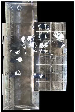
snapshots recorded by the video cameras. From those acquired snapshots, a unique panoramic image of the area of interest with a 1280 × 1960 pixel resolution was generated (Figure 10).
Figure 10. Synchronised acquisition of the 10 snapshots recorded by the video cameras.
A panoramic top-view image of the observed area was crucial in order to obtain images that showed the true shape of cow’s body when walking activity occurred. The video-recording
-46 -
system was successfully applied for cow lying recognition and the discrimination of feeding from standing by using the Viola-Jones algorithm (Porto et al., 2014, 2015; Porto et al., 2013).
4.2.4 The walking analysis and the step counting
The experiment was carried out during June 2015. The duration of the experiment was established by considering the daily time budget usually spent by a dairy cow bred in a free-stall barn (Grant and Albright, 2000). Since the aim of the proposed algorithm is to count steps of dairy cows, the data acquisition system was operated for about 5 hours during the time intervals characterised by standing or walking activities (Porto et al., 2016), i.e., between 13:00 and 18:00.
Since each cow of the herd could show differences in walking activity, in this study five cows (named with an identification number, i.e., ID 1, ID 2, ID 3, ID 4, and ID 5, in the following of the text) were selected from the observed group of 14 animals in order to consider differences in acceleration data. Therefore, the walking activity of each cow constituted the reference population from which acceleration samples were extracted and statistically analysed for each cow individually. Then a group comparison method was carried out in order to test any difference in acceleration data among the considered populations.
The five cows were randomly selected and their behaviour was not forced during the experiment. These two conditions assured that independent samples could be extracted from the walking activity of each cow.
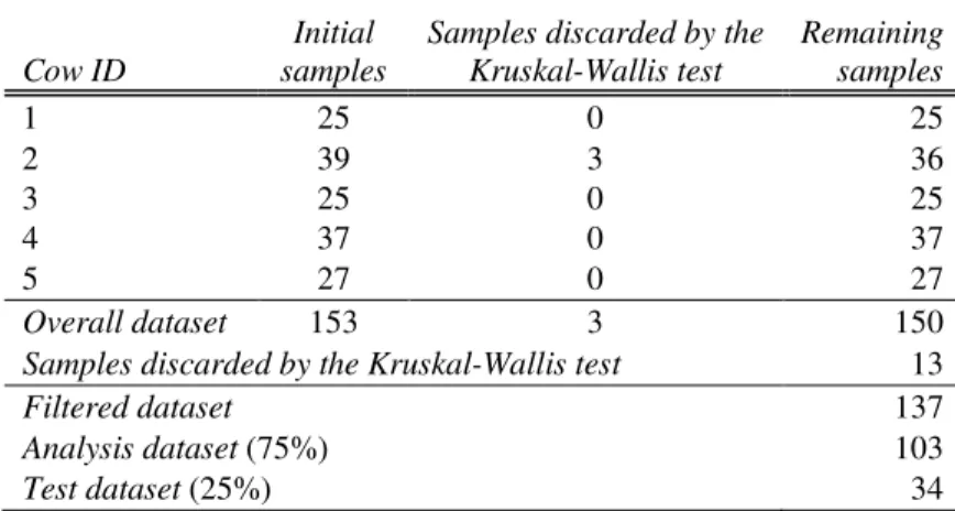
The walking samples selected were: 25 for the cow with ID 1, 39 for the cow with ID 2, 25 for the cow with ID 3, 37 for
-47 -
the cow with ID 4, and 27 for the cow with ID 5; therefore, a total of 153 samples were collected.
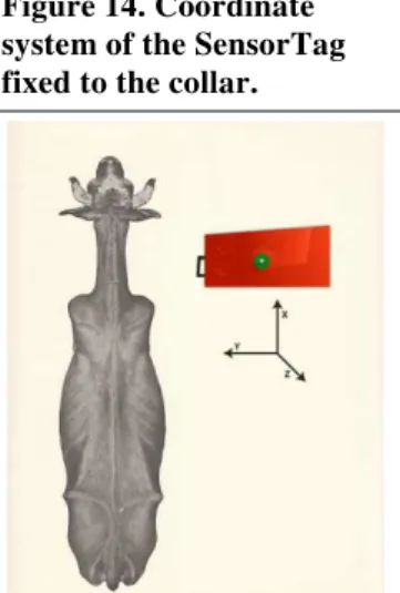
To acquire acceleration values, a SensorTag was fixed to the left hind leg of each animal (Figure 11).
Figure 11. SensorTag fixed at left hind leg.
Each SensorTag was protected by inserting it into a bubble wrap and, in turn, into a water-resistant plastic case, which was equipped with a belt and a Velcro closure. An adhesive label, which contained the identification code of the SensorTag, was fixed on each case.
The position of the SensorTag on the cow's leg was decided based on the findings of Firk et al. (2002). They found that, when the device is positioned at the collar, a higher number of false positives are likely to be obtained in oestrus detection than when it is fixed at the leg, whereas no significant differences were reported in their study between the choice of the left hind leg and that of the fore-leg.
-48 -
Figure 11 shows the coordinate system of the SensorTag in relation to the cow's leg. Consequently, the leg motion during walking activity of the cow essentially developed in the x-y plane.
Each cow was marked with a unique visible sign to enable visual assessment of behavioural activity by using the images collected by the video-recording system described above (see Section 4.2.3).
Before starting the data collection, the clock of the Raspberry Pi was synchronised with the one of the existing video-recording system that was utilised as validation system. The data acquired by the two systems, i.e., accelerometers and video-recording systems, were analysed at the end of the experiment in the barn. The walking activity of the five cows was extracted from the accelerometer recordings with the support of the video-recording system image visualisation. According to Alsaaod et al. (2015), a walking period was defined as a period of at least three consecutive steps to avoid that isolated movements (e.g., a flick of the leg) could be misinterpreted as steps. Moreover, when the time interval between two steps exceeded 4 s, the two steps were attributed to two different periods of walking.
In order to decide which duration of walking samples is more suitable for cows’ walking activity, literature was analysed. Some authors (Nielsen et al., 2010) obtained the most accurate results by using walking samples of at least 5 s, whereas Robert et al. (2009) reported a more accurate behaviour classifications with samples of 3 s and 5 s than with samples of 10 s, for the recognition of standing, walking, and lying behaviours.
Therefore, based on the literature outcomes, in this study, the cows’ walking activity was subdivided into samples of 5 s;
-49 -
since the system used in this study operated at 4 Hz frequency, each sample included 20 instantaneous measurements of the acceleration. In the following discussion, the term 'observation' will be used to refer to a single measurement of acceleration. Furthermore, at each walking sample a univocal alphanumeric code was assigned by joining the cow’s ID, the symbol ‘_’, and the progressive number of the sample.
In literature, different variables have been considered to study the accelerometer signals. In this study, according to Robert et al. (2009), two vector variables were utilised to measure the accelerometer data: the Signal Vector Magnitude (svm), named mod hereafter, and Signal Magnitude Area (sma). They were defined as follows:
= + (2)
= | | + (3)
where accx and accy represent the components of acceleration in
the x and y directions, respectively. In this study, the two variables modxy and smaxy were utilised independently.
Since leg motion during this activity essentially developed in the x-y plane, the accelerometer data related to the z axis was neglected in the analysis of cow walking behaviour.
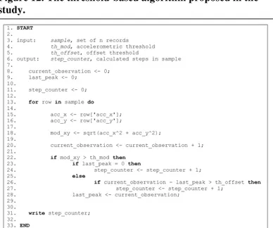
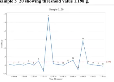
Successively, two versions of an innovative algorithm for step counting, which utilises two thresholds, were developed.
A first version, named hereafter, used the main threshold ℎ , which was an acceleration and was suitable for detecting the presence of a step in the sample. In this regard, the observations having an acceleration value higher than the fixed threshold
-50 -
hereafter, was defined to detect if two peaks should be assigned to the same step or else to two different steps. Therefore, the
parameter ( , ) was defined as the number of
observations between two peaks, and . The detailed description of the algorithm is reported in Figure 12.
Figure 12. The threshold-based algorithm proposed in the study.
By following the same methodology, a second version of , named hereafter, was defined. It uses the variable
instead of with the corresponding thresholds ℎ
and ℎ .
With the aim to determine the values ℎ and ℎ , the walking samples were used twice to compute the variables
and . They constituted initial datasets of the two versions of the step counter algorithm.
-51 -
Before carrying out threshold computation, for each reference population of walking activity it was verified that values of the walking samples, as well as , were not statistically different among them in the time interval of data acquisition. This test was useful to check for and outliers.
To obtain a unique acceleration threshold for each version of the algorithm, suitable for counting the steps of all the cows, a method was adopted to test the equality of accelerations obtained from the considered cows. Since the two variables and did not follow a normal distribution, the non-parametric Kruskal-Wallis test was used as group comparison test. This test made it possible to verify the equality of acceleration medians for the reference populations, i.e., the walking periods of the five cows analysed, and produced two new datasets for and . These new datasets were used in the analysis and testing phases of the algorithms. In detail, the datasets were subdivided as follows: 75% of the walking samples constituted the datasets
_ and _ which were
used to compute ℎ and ℎ , respectively; the remaining 25% of the walking samples composed the datasets
_ and _ , which were used to test
the two versions of the algorithm, and .
The threshold values ℎ and ℎ were computed as the maximum of the five acceleration medians in their respective datasets.
The determination of the ℎ was based on considerations regarding the acceleration time plots. It included, for instance, the duration of a cow’s step and the number of observations occurring between two consecutive steps (typically 2 observations). The ℎ value depended on the 4 Hz sampling frequency; in fact, a higher sampling frequency will cause a higher value of ℎ .
-52 -
In the testing phase, the number of cow’s steps ( ) computed by the algorithm were compared with the number of steps observed in the video-recordings ( ).
The indicators selected to evaluate the accuracy of the two versions of the algorithm were the following:
=∑ ∑ × 100% (4)
= ∑ ∑ ∑ × 100% (5)
where k is the number of walking samples in the datasets
_ or _ .
The first indicator (E) takes into account the total error when an overestimation ( ) or an underestimation ( ) of the number of steps occurred. The second indicator named Relative Measurement Error (RME) takes into account the compensation between and and allowed the comparison with another study (Alsaaod et al., 2015).
Furthermore, different values of the thresholds ℎ , ℎ , and ℎ were applied to conduct a sensitivity analysis suitable for determining how different values of the thresholds affected the error produced by the two versions of the algorithm. In detail, ±5% and ±10% variations of ℎ and ℎ were applied and the values 1, 3, and 4 were considered for ℎ .
4.2.5 The feeding classifier
The field experiments were carried out during June 2015 in a free-stall barn for dairy cows located in Sicily. In this study, the central pen of the barn, which housed a group of 14 primiparous cows, was selected.