…..Niente è impossibile,
al massimo è poco probabile…
AKNOWLEDGEMENTS
Three years ago, pushed by my curiosity about a so strange material I have start an experience that I never forget for its professional and human teachings; my dissertation is the result of this. Since that day in which I have met Prof. Franco Furgiuele and Eng. Carmine Maletta, I knew that I am going to work not only with two talented researches but also with two good and generous men. They have permit me to go in for the passion for the research in a very stimulant and cultured set and to have satisfaction by my work. For their availability and affection I will be always grateful to them.
Very thanks to my girlfriend Beatrice that have accepted faithfully and gladly the challenges and uncertainties associated with the life of a doctoral student; her love and patience are for me essential.
Finally, a special thanks to my father and my mother, always present with their love and support; all this could not be possible without them.
TABLE OF CONTENTS
PAGE
INTRODUCTION AND SCOPE OF RESEARCH 7
CHAPTER1-GENERAL PROPERTIES OF NICKEL-TITANIUM SHAPE MEMORY ALLOYS
1.1HISTORY OF SHAPE MEMORY ALLOYS
1.2THERMOELASTIC MARTENSITIC TRANSFORMATION
1.3MECHANICAL AND FUNCTIONAL PROPERTIES OF NITI ALLOYS 1.3.1SHAPE MEMORY EFFECTS (SME)
1.3.2SUPERELASTIC BEHAVIOUR
1.3.3TWO WAY SHAPE MEMORY EFFECT (TWSME) 1.4CYCLIC LOADING AND MARTENSITE STABILIZATION 1.5EFFECT OF STRAIN RATE
1.6ASPECT RELATED TO THE PRODUCTION OF NITI ALLOYS 1.6.1ALLOY COMPOSITION 1.6.2MANUFACTURING PROCESSES 1.6.3MACHINING OF NITI ALLOYS 10 11 15 18 19 20 22 23 24 24 25 27
CHAPTER2–CHARACTERIZATION OF SHAPE MEMORY BEHAVIOUR IN NITI ALLOYS
2.1 Introduction
2.2 Characterization of a Ni-51 %at. Ti alloy 2.3 Results
2.3.1 Effect of thermal treatment and mechanical behaviour 2.3.2 Training and TWSME
28 29 30 30 33
CHAPTER3- LASER WELDING OF NITI ALLOYS: MECHANICAL AND SHAPE MEMORY BEHAVIOUR
3.1OVERVIEW
3.2 WELDING PROCESS
3.2.1WELDING EQUIPMENT AND WELDED JOINT PREPARATION 3.3MICROSTRUCTURE AND MECHANICAL BEHAVIOUR OF WELDED JOINTS
3.3.1DSC TESTS
3.3.2 MICRO-HARDNEES TESTS AND MICROSCOPIC INVESTIGATIONS 3.3.3MECHANICAL BEHAVIOUR
3.4SHAPE MEMORY BEHAVIOUR OF NITI WELDED JOINTS 3.4.1SPECIMEN PREPARATION AND EXPERIMENTS
3.4.2.MICRO-HARDNEES TESTS AND MICROSCOPIC INVESTIGATIONS 3.4.3 EFFECT OF THERMAL TREATMENT
3.3.4 TRAINING AND TWSME
44 46 48 52 53 54 58 61 61 62 63 65
CHAPTER5–NUMERICAL MODELLING OF TWSME IN NITI ALLOYS
5.1OVERVIEW
5.2NUMERICAL MODELLING OF TWSME 5.2.1NUMERICAL MODEL
5.2.2VALIDATION OF THE PROPOSED MODEL
71 74 79 87
CHAPTER4-BIOMIMETIC COATING OF NITI ALLOYS
5.1OVERVIEW 5.2EXPERIMENTAL
5.2.1 PREPARATION OF SUBSTRATES 5.2.2BIOMIMETIC COATING PROCEDURE
93 96 96 97
5.3RESULTS
5.3.1ANALYSIS OF TREATED SURFACES 5.3.2 ANALYSIS OF COATED SURFACES
97 98 98
CONCLUSIONS &FUTURE WORKS 110
INTRODUCTION AND SCOPE OF RESEARCH
In this dissertation, the results of the research activities carried out during the Doctoral Course at the University of Calabria are presented. The aim of these activities regarded the interesting field of Smart Materials and, in particular, some aspects related to the thermomechanical characterization of Nickel-Titanium (NiTi) Shape Memory Alloys (SMAs).
Smart Materials are able to note an external stimulus responding in a predetermined and repeatable manner; this capacity permits to interact with the material using it as an actuator able to modify shape and elastic properties, electric resistivity and damping capacities.
Shape Memory Alloys, and in particular the NiTi alloys, are the most promising Smart Materials. Due to their special functional properties, namely one way or two way shape memory effect (OWSME, TWSME) and superelastic effect (SE), NiTi alloys have seen growing use in recent years in a number of industrial fields as biomedical, automotive, aeronautic and many others. Generally, the use of the NiTi alloys seems to be very useful in applications were it is necessary to use smart components with low dimensions; many conventional actuators and sensors can be substituted with NiTi components obtaining high advantages in terms of reduction of weight and dimensions, reliability and costs. Furthermore, in the last years, their use for the realization of smart composites, as an example for vibration and shape control, is becoming very interesting. Unfortunately, there are still some difficulties with shape memory alloys that must be overcome before they can live up to their full potential. For example, these alloys are still relatively expensive to manufacture compared to other materials such as steel and aluminium. This difficulties regard the high sensibility to the production parameters, to the low workability with conventional machining processes as well as to the high non linearity in the mechanical and functional behaviour.
For this reason, in the last decades, many research activities have been addressed to the investigation of many aspect related to the influence of different working processes on the behaviour of the NiTi alloys and to develop simple numerical model able to simulate the non linearity associated to the NiTi functional properties.
In this dissertation, the results related to the experimental characterization and numerical modelling of different NiTi alloys are presented.
The experimental characterization are carried out on NiTi sheets in order to study the mechanical and functional behaviour of different NiTi alloys. Using proper experimental procedure, the thermomechanical behaviour of the materials are investigated under static and cyclic conditions to better understand the deformation mechanisms involved in the shape memory and superelastic effect.
Furthermore, the characterization of Nd:YAG laser butt welded NiTi sheets, in terms of mechanical, microstructural and shape memory behaviour, was executed in order to investigate the influence of this working process on the alloy behaviour. As said before, in fact, due to the low workability of these materials with conventional machining processes (milling, turning and drilling), suitable joining and cutting techniques must be used to obtain devices and components with complex geometries. In this field, laser welding is probably a good solution because, due to its high precision, permits to reduce the influence of the machining process on the material properties.
Then, starting from some experimental results and evidences, a phenomenological approach, based on the Prandtl-Ishlinskii hysteresis operators, was used to model the TWSME in NiTi alloys. Modelling the hysteretic behaviour of a smart material is not a simple task because the identification of many model parameters is required to adapt the model to the real behaviour of the material. For this reason, the developing of useful models based on a phenomenological approach could resolve many problems related to the simulation and control of this class of materials.
Finally, another important aspect related to the use of these alloys in biomedical field is investigated. Various approaches are currently under development to prevent undesirable Ni release and ensure implant safety in applications in which NiTi alloys are used at direct contact with the human tissues. Despite the satisfactory clinical use of NiTi, in some situations the high Ni content in the alloy is of great concern with regards to its biocompatibility; in fact, Ni has been reported to be responsible for the clinic toxic and allergic responses. It is theoretically possible that Ni may dissolve from NiTi due to corrosion phenomena, so that its necessary to modify the surface of NiTi alloys to improve their biocompatibility and restraining Ni release. Furthermore, coating NiTi
components with osteoconductive materials could improve their use in the realization of biomedical implants useful for the regeneration or substitution of bone in human body In this research, a Calcium-Phosphates (CaPs) coating, was deposited by a biomimetic procedure on a NiTi alloy. The aim is to analyze the properties of the coatings, as function of different surface conditions of the material, in order to define a useful coating procedure.
C
HAPTER
1
N
ICKEL
-
T
ITANIUM
S
HAPE
M
EMORY
A
LLOYS
1.1
H
ISTORY OF SHAPEM
EMORYA
LLOYSThe first reported steps towards the discovery of the shape memory effect were taken in the 1930s, when A. Ölander discovered the pseudoelastic behaviour of the Au-Cd alloy in 1932 (Otsuka, 1998). Greninger & Mooradian (1938) observed the formation and disappearance of a martensitic phase by decreasing and increasing the temperature of a Cu-Zn alloy. The basic phenomenon of the memory effect governed by the thermoelastic behaviour of the martensite phase was widely reported a decade later by Kurdjumov & Khandros (1949) and also by Chang & Read (1951).
In the early 1960s, Buehler and his co-workers at the U.S. Naval Ordnance Laboratory discovered the shape memory effect in an equiatomic alloy of nickel and titanium, which can be considered a break trough in the field of shape memory materials (Buehler et al. 1967). This alloy was named Nitinol (Nickel-Titanium Naval Ordnance Laboratory).
Since that time, intensive investigations have been made to elucidate the mechanics of its basic behaviour. The use of NiTi as is fascinating because of its special functional behaviour, which is completely new compared to the conventional metal alloys.
1.2
T
HERMOELASTICM
ARTENSITICT
RANSFORMATIONNiTi shape memory alloys can exist in a two different temperature-dependent crystal structures (phases) called martensite (lower temperature) and austenite (higher temperature or parent phase). Several properties of austenitic NiTi and martensitic NiTi (such as Young modulus, electrical resistance, damping behaviour, etc..) are notably different (Otsuka et al. 2005, Duering et al. 1990).
The austenite is characterized by a Body Centered Cubic structure (BCC), where there is a nickel atom at the center of the crystallographic cube and a titanium atom at each of the cube’s eight corners. Since the austenitic phase is microstructurally symmetric it is considered to be the parent phase. The martensite phase of NiTi is less symmetric and its lattice structure consists of a rhombus alignment with an atom at each of the rhombus corners. Fig.1 shows two NiTi crystals in the austenite and martensite phases.
The unique behaviour of NiTi is based on the temperature dependent austenite to martensite phase transformation on an atomic scale, which is called Thermoelastic Martensitic Transformation (TMT). TMT causing the functional properties as a result of the need of the crystal lattice structure to accommodate to the minimum energy state for a given temperature (Otsuka et al. 1998).
TMT, and its reversion, is a shear-dominant diffussionless solid-state phase transformation occurring by nucleation and growth of the martensitic phase from the parent austenitic phase. TMT could be activated, so that NiTi alloys could be transformed from austenite to martensite and vice versa, either by reducing the temperature (Thermally Induced Martensite, TIM) or applying a mechanical stress (Stress Induced Martensite, SIM). On the other hand the martensite transforms into austenite through either increasing the temperature or removing the applied stress. This shows that mechanical loading and thermal loading have opposite effects on NiTi alloys.
(a) (b)
Fig. 1: (a) Austenite and (b) Martensite lattice structures
When austenite is cooled, it begins to change onto martensite; the temperature at which this phenomenon starts is called martensite start temperature (Ms), while the
temperature at which martensite is again completely reverted is called martensite finish temperature (Mf). When martensite is heated, it begins to change into austenite; the
temperature at which this phenomenon starts is called austenite start temperature (As),
while the temperature at which this phenomenon is complete is called austenite finish temperature (Af). (Buehler et al. 1967, Duering et al. 1990).
Due to the TMT characteristics, applied stress plays a very important role. During cooling of the NiTi material below temperature Ms in absence of applied stresses, the
variants of the martensitic phase arrange themselves in a self-accommodating manner, with a total of 24 crystallographically equivalent habit planes, resulting in no observable macroscopic shape change. The mechanism by which single martensite variants form from austenite by cooling is called twinning and it can be described as a mirror symmetry displacement of atoms across a particular atom plane, the twinning plane (Buehler et al. 1967, Otsuka et al. 2005). Crystal twinning occurs when two separate crystals share some of the same crystal lattice points in a symmetrical manner. The result is an intergrowth of two crystals in a variety of specific configurations separated by a twin boundary surface. Twin boundaries occur when two crystals of the same type intergrowth, so that only a slight misorientation exists between them. Twin boundaries are partly responsible for shock hardening and for many of the changes that occur in cold work of metals with limited slip systems or at very low temperatures (Hurlbut et al. 1985).
By applying mechanical loading on the martensitic structure, martensitic variants reorient into a single variant; the reorientation mechanism is called detwinning (Liu 2005, Otsuka et al. 2005) and it is the cause of the shape memory behaviour in the SMAs as explained in the following sections.
The martensitic phase transformation can also be induced by pure mechanical loading while the material is in the austenitic phase, in which case detwinned martensite is directly produced from austenite by the applied stress at temperatures above Ms (SIM).
This means that the energy necessary for the martensitic transformation can be provided, not only by a thermal input but also by a mechanical input (Otsuka et al. 2005, Duering et al. 1990). It is important to point out that the SIM transformation can be induced in the material at temperatures up to Af but lower than a threshold value
defined as Md. Up to this temperature, an applied stress do not generate the SIM
transformation but dislocation effects as consequence of the minor energy needs with respect to the SIM.
Fig. 2 shows the NiTi in austenitic and martensitic forms in a two dimensional view. As shown in the figure, the austenite is symmetric and thus has one layout for the atoms, while the martensite could be found in two different alignments based on the level of stress applied to the alloy. Based on the stress direction, the martensite could be detwinned either to the left or to the right direction. Thus from a two dimensional point of view there are two possible variants for martensite.
(a) (b) (c) Fig. 2: Austenite and martensite microstructural view in a two-dimensional plan:
(a) austenite, (b) twinned martensite, (c) detwinned martensite
Fig. 3 summarizes the above considerations showing the relationship between the phase transformation temperatures, the applied stress and the crystalline structure of a NiTi alloy.
From the figure, it is possible to observe that an increase in the applied stress increases the four phase transformation temperatures in a linear manner. In particular, the effect of the applied stress can be computed according to the well known Clausius-Clapeyron rule, dσ dT =const (Otsuka et al. 2005).
Fig. 3: Relationship between phase transformation temperatures and applied stress
In Fig. 4, a Differential Scanning Calorimetry (DSC) thermogram related to a NiTi alloys is shown; this technique is the main used to identify the transformation temperatures of the NiTi alloys. As clearly shown in the figure, the temperature range for the martensite to austenite transformation, that takes place upon heating, is somewhat higher than that for the reverse transformation upon cooling. The difference between the transition temperatures upon heating and cooling is called hysteresis. Hysteresis is generally defined as the difference between the temperatures at which the material is 50 % transformed to austenite upon heating and 50 % transformed to martensite upon cooling. This difference can be up to 30-40 °C and it is associated with the energy dissipated during the transformation (Otsuka et al. 2005, Buehler et al. 1967). A hysteretic behaviour is also present in the stress induced martensitic transformation in terms of transformation stress as explained in the following; generally, the hysteretic behaviour characterizes all NiTi properties.
Fig. 4: DSC thermogram of a NiTi alloy
1.3
M
ECHANICAL AND FUNCTIONAL PROPERTIES OFN
IT
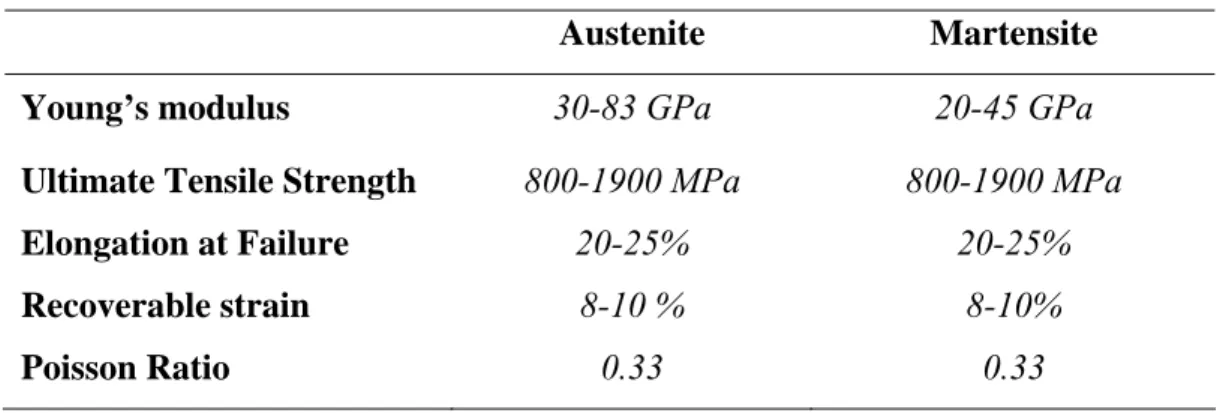
I ALLOYSA relatively large number of researchers have been interested in exploring the mechanical characteristics of NiTi in its two phases. Researchers are interested in studying and specifying the properties of NiTi materials under various types of thermomechanical loadings. Several experimental studies have been conducted to specify the mechanical properties of SMAs (Otsuka et al. 2005, Brinson et al. 2004, Liu et al. 1998, Lagoudas et al. 2000, Gall et al. 2001, Wada et al. 2005). The outcomes of experimental research in the past two decades assisted in developing a range for the mechanical parameters that would be expected from NiTi in its austenite and martensite phases. Table 1 presents a summary of the mechanical properties for NiTi. As explained in the following, mechanical properties could be due to several factors such as alloys composition, manufacturing process, strain rate and cyclic loading.
Table 1: Summary of NiTi mechanical properties
Austenite Martensite Young’s modulus 30-83 GPa 20-45 GPa
Ultimate Tensile Strength 800-1900 MPa 800-1900 MPa
Elongation at Failure 20-25% 20-25%
Recoverable strain 8-10 % 8-10%
Poisson Ratio 0.33 0.33
Fig. 5 illustrates the mechanical behaviour of a NiTi alloy as a function of temperature. In order to relate the mechanical behaviour of the alloy which occurs on the macro level with the phase transformations that occur on the micro level, the microstructure of the alloy is shown in the figure at the various strain/temperature levels (Shaw 2002).
While most metals deform by slip or dislocation, NiTi responds to stress by simply changing the orientation of its crystal structure through the movement of twin boundaries (detwinning). This orientation is evident in the stress-strain behaviour by the stress plateau that occurs both in martensitic than in austenitic NiTi, until the material consists only of the correspondence variant which produces maximum strain. However, deformation beyond this will result first in elastic deformation of the oriented structure and than in classical plastic deformation by slip and dislocation.
At low temperature, so that in martensitic condition, the mechanical behaviour of the material is characterized by large inelastic deformation after unloading that could be recovered by heating the alloy (Shape Memory Effect, SME). As the multivariant martensitic phase is deformed, a detwinning process takes place, as well as growth of certain favourably oriented martensitic variants at the expense of other variants. The mechanical loading in the martensitic phase induces reorientation of the variants and results in a large inelastic strain, which is not recovered upon unloading. At the end of the deformation, and after unloading, it is possible that only one martensitic variant remains if the end of the stress plateau is reached; otherwise, if the deformation is halted midway, the material will contain several different correspondence variants. This mode of deformation dominates at temperatures lower than Mf and results in the stress plateau
Fig. 5: Stress (Σ)-strain (δ/L)-temperature (θ) relationship in shape memory alloys (Shaw, 2002)
Instead, at high temperatures, the stress-strain relation exhibits a flag shape. The figure demonstrates that the stress plateau at high temperatures is developed due to the conversion of austenite to detwinned martensite. During unloading, the detwinned martensite transforms in austenite due to its instability at temperature up than Af, so
that, a lower stress plateau, related to the reverse transformation, appears in the stress-strain curve (Superelastic Effect, SE), generally, without inelastic stress-strain (Otsuka et al. 2005, Duering et al. 1990).
The above descriptions are related to ideal deformation behaviour of the material; in the following chapter, starting from experimental results, a better description of the mechanical behaviour is reported.
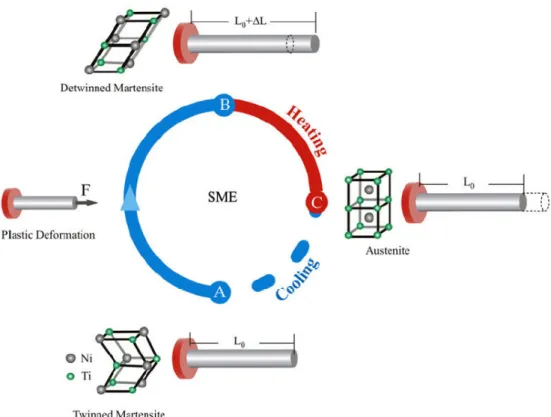
1.3.1 SHAPE MEMORY EFFECT (SME)
NiTi alloys exhibits the Shape Memory Effect (SME) when it is deformed while in the martensitic phase and then unloaded while still at a temperature below Mf. If it is
subsequently heated above Af it will regain its original shape by transforming back into
the parent austenitic phase as schematically shown in Fig. 6 and represented in Fig. 5 in terms of stress-strain-temperature curve.
The stress-free cooling of austenite produces a complex arrangement of several variants of martensite. Self-accommodating growth is obtained such that the average macroscopic transformation strain equals zero, but the multiple interfaces present in the material (boundaries between the martensite variants and twinning interfaces) are very mobile. This great mobility is the heart of the SME; movement of these interfaces accompanied by detwinning is obtained at stress levels far lower than the plastic yield limit of martensite but, as said before, after unloading, large inelastic strain can be observed.
The reverse transformation induced by heating recovers the inelastic strain; since martensite variants have been reoriented by stress, the reversion to austenite produces a large transformation strain having the same amplitude but the opposite direction with the inelastic strain and the SMA returns to its original shape of the austenitic phase. Note that subsequent cooling will result in multiple martensitic variants with no substantial shape change (self-accommodated martensite).
The above described phenomenon is called one-way shape memory effect (or simply, shape memory effect) because the shape recovery is achieved only during heating.
Fig. 6: Shape memory effect phenomenon in shape memory alloys
1.3.2 SUPERELASTIC EFFECT (SE)
The superelastic behaviour of NiTi alloys is associated with the recovery of the deformation upon unloading known as Superelastic Effect (SE). The superelastic behaviour is observed during loading and unloading above Af and is associated with
stress-induced martensitic transformation and reversal to austenite upon unloading. As said before, if the alloy is externally stressed at a temperature above Af , it deforms
transforming into a detwinned martensite, which is unstable at high temperatures, thus when the load is removed the SMA transforms back into austenite and the original shape of the alloy is fully recovered. The loading and unloading paths during this loading cycle do not coincide, with the unloading path being a lower stress plateau compared to the loading plateau. As a result, there is an area enclosed under the stress-strain diagram which represents the energy dissipated during the transformation. A schematic representation of the superelastic phenomenon is illustrated graphically in Fig. 7 and represented in Fig. 5 in terms of stress-strain-temperature curve.
Fig. 7: Schematic representation of Superelastic Effect in shape memory alloys
1.3.3 TWO WAY SHAPE MEMORY EFFECT (TWSME)
In the shape memory effect discussed in the preceding section, what is remembered was the shape of the parent phase only; however, under certain conditions it is possible to remember the shape of the martensitic phase. This effect was first called ‘‘the reversible shape memory effect’’ (Nagasawa et al. 1974, Saburi et al. 1974), but now it is called two-way shape memory effect (TWSME), while the ordinary shape memory effect in the preceding section is sometimes called one-way shape memory effect (OWSME), in contrast to two-way. Whereas the SME and SE are intrinsic in the material, the TWSME can be observed only after proper thermomechanical procedure called training. Due to this property, it is possible to modify the shape of the material, in a reversible way between two different ones and without applied stress, only by changing of temperature across Af and Mf. As reported in the previous sections, due to the hysteresis in the transformation temperatures the TWSME is characterized by a strongly non linear hysteresis loops. Unfortunately the intrinsic two-way effect suffers a quite strong deterioration during the working cycles due to microstructural changes (Scherngell et al. 1998). Promising approach to improve the stability of the effect is reported in literature; the aim is to increase the intensity of internal stresses that it is possible by different microstructural features (Scherngell et al. 1998).
The first report of two-way shape memory effect is due to Wang and Buehler [260] for a Ti–Ni alloy; however, a more clearly description of the phenomena is reported by Nagasawa et al. that describe, for Ti–Ni, Cu–Zn and Ni–Al alloys, a reversible shape memory effect obtained when specimens are severely deformed below Ms temperature.
A schematic representation of the observed behaviour is reported in Fig. 8.
Fig. 8: Schematic representation of Two Way Shape Memory Effect
Thereafter many reports appeared how to realize two-way shape memory effect including the above: (1) introduction of plastic deformation, (2) constraint aging (Takezawa et al. 1976), (3) thermal cycling (Schroeder et al. 1977), (4) utilization of precipitates (Oshima et al 1975, Nishida et al, 1981) and others. Miyazaki et al. (1982) show that there are different possibilities to induce an intrinsic two-way effect
It will be easily expected that in order to realize the shape of martensitic phase, certain martensite variants need to be selected. Since the martensitic transformation strongly interacts with stress, the stress selects certain variants of martensite in the nucleation process in order to lower the energy of the system (Otsuka et al, 1977) and contributes to create the certain shape of martensite. In the above process (1)–(4), certain stress sources are created during the processes such as dislocation configurations, precipitates etc., which produce internal stress fields to choose specific martensite variants. It is clear from the above that two-way shape memory effect is a rather weak effect
compared to one-way shape memory effect, since the former is due to the selective nucleation of certain martensite variants, while the latter is due to the strong reversibility and unique lattice correspondence upon reverse transformation.
In the following chapter, an experimental investigation of the TWSME induced by martensite deformation in a NiTi alloy is reported.
1.4
C
YCLIC LOADING AND MARTENSITE STABILIZATIONThe cyclic loading effects on NiTi alloy mechanical behaviour has been studied by a large number of researchers; they are in agreement that the changes in the mechanical properties that are associated with the cyclic loading are mainly referred to the martensite stabilization effect, or better to the accumulation of residual martensite at each cycle. This residual martensite is permanent martensite and thus never participates in proceeding phase transformation cycles. The residual strain measured during cycling increase with increasing the number of cycles confirming that at each cycles more and more martensite is stabilized (Otsuka et al. 2005, Tanaka et al., 1995, Liu 1999, Liu et al. 1998, Tobushi et al. 1996; Friend et al. 1999; Gall et al. 1999).
The stabilization effect was observed as an increase in the critical temperatures for the reverse transformation of the deformed martensite; this effect vanishes once the deformed martensite is reverted back to austenite (Otsuka et al. 2005, Tanaka et al. 1995, Liu et al. 1998). In terms of stress-strain curves, this particular effect is evident in the decreasing of the stress for the onset of the plateau, in the increase of its slop and, for an austenitic alloy, in the reduction in the area of hysteresis loops (Otsuka et al. 2005, Liu et al. 1998, Brinson et al. 2004). However, these effects in a polycrystalline alloy are due to the interaction between martensite stabilization and plastic deformation that develop in the material during cycling (Otsuka et al. 2005, Tanaka et al. 1995, Liu et al. 1998 and 1999).
Experimental evidences of martensite stabilization for a martensitic NiTi alloy are reported in the following chapters.
1.5
E
FFECT OF STRAIN RATEThe effects due to the strain rate on the NiTi behaviour is an important aspect to be considered above all for understanding its applicability in damping control applications. In these types of applications, the intrinsic damping properties of the martensitic phase and the energy dissipation capability of the material in its austenitic condition (Otsuka et al. 2005) could be successfully used. In particular, in the last decades, NiTi alloys seems to be useful for realizing smart composites for the damping and vibration control (Basavaraj et al 2006, Hurlebaus et al. 2006, Yuse et al. 2005, Nagai et al. 2006, Ogisu et al. 2006). Their use as seismic dampers is also investigated by some researchers (Grasser et al. 1991, De Roche et al. 2002, Dolce et al. 2000).
Many researchers (Dolce and Cardone 2001; Delemont 2002; and Tobushi et al. 1998) have focused their interest on studying the behaviour of NiTi when subjected to dynamic loading with various strain rates. Most of these researchers agree that loading rate affects the mechanical behaviour of the alloy (Graesser et al. 1991, Dolce et al. 2001).
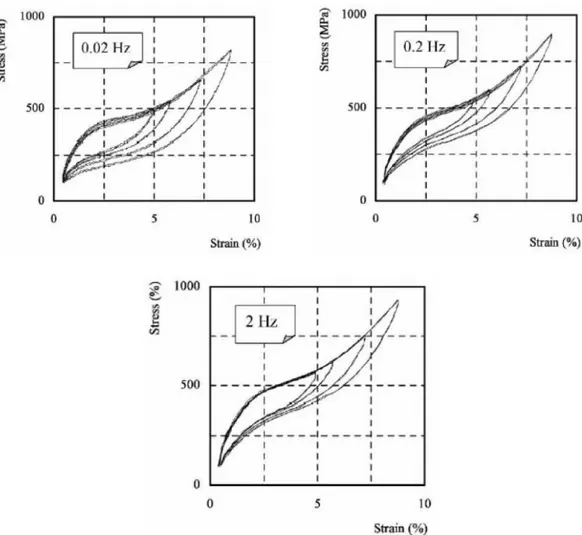
In 2001 Dolce and Cardone conducted a series of experimental tests using NiTi wires under tensile loads with a strain rate that varied between 0.01 and 4 Hz; Figs 9 is related to 0.02 Hz, 0.2 Hz and 2 Hz as strain rates for the cyclic load; the results show as the rate of loading is increased the loading and unloading plateau are shifted upwards. This shift is associated with a reduction in the hysteresis area. The authors found that the change in behaviour tends to stabilize after a strain rate equal to 0.2 Hz, and no more significant changes in the stress-strain curve were noticed. On the other hand, Tobushi and his colleagues in 1998 conducted a series of experimental tests using strain rates that were smaller compared to Dolce and Cardone. Tobushi et al. found that at very small rates of loading, the stress-strain curves of the alloys are stable while at higher strain rates the martensitic phase transformation is increased.
Most of the researchers agreed that the reason for such change in the material mechanical behaviour at higher strain rates is the fact the material releases heat during the martensitic transformation and absorbs heat in the reverse transformation. If the strain rate is high, there will not be enough time for the material to transfer or absorb heat from the surrounding environment and this might lead to self-heating of the
material, which results in changing the mechanical characteristics of the alloy (Wu 1996, and Dolce et al. 2001).
Fig. 9: Stress-strain curves for austenite NiTi alloy at 0.02 Hz, 0.2 Hz, and 2.0 Hz strain rates (Dolce and Cardone, 2001)
1.6
A
SPECTS RELATED TO THE PRODUCTION OFN
IT
I ALLOYS1.6.1 ALLOY COMPOSITION
General requirements on Nitinol chemistry and trace elements are defined in an ASTM standard, F2063-00. The chemical composition of the alloy affects directly the phase transformation temperatures (Birman, 1997 and Serneels 1999, Otsuka et al 2005), which plays an important role in defining the alloys mechanical properties as explained
weight percent deviation in Ni (or Ti) concentration would result in approximately a 100°C shift in transformation temperatures. This extreme sensitivity puts a strict requirement on any melting practice to tightly control the Ni and Ti ratio in order to meet the required tolerance in transformation temperatures.
Generally, a significant decrease of the Af temperature is observed increasing Ni content in the alloy. A reduction of the hysteresis width in the characteristic transformation temperature and stresses is also clearly explained (Serneels, 1999). There has been much effort to modify Ti–Ni shape memory alloys by adding various alloying elements to the binary system. It was found alloying elements often alters transformation temperature greatly. The effect of third element on transformation temperature are clearly reported in the literature (Homa et al. 1987, Angst et al. 1995)
1.6.2 MANUFACTURING PROCESS
After melting, the Nitinol ingot is usually forged and rolled into a bar or a slab at elevated temperatures. Optimal hot working temperatures appear to be around 800°C where the alloy is easily workable and the surface oxidation in air is not too severe (Suzuki, 1998). Following hot working, NiTi alloys are cold worked and heat-treated to obtain final dimensions with desired physical and mechanical properties. Generally, cold work percentage between 15% and 40% and thermal treatment at temperatures between 350 °C and 700 °C are used.
The mechanical behaviour of NiTi is determined by the method used to process the alloy (Otsuka et al. 1998 and 2005). The combination of the effects due to cold work and heat treatment defines the material behaviour in terms of both mechanical and functional properties.
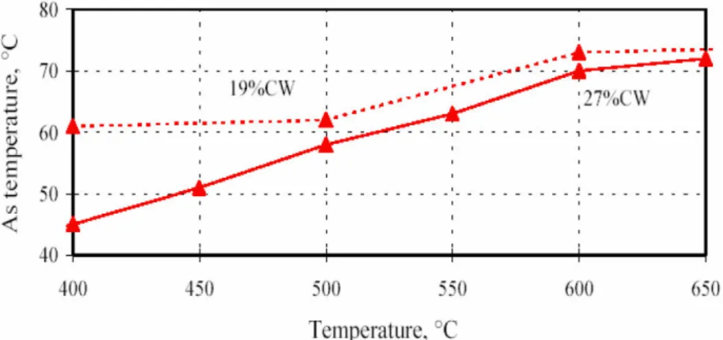
As example, in Figs 9 and 10, the effects of different thermal treatments and cold working on the material transformation temperatures are reported.
In particular, Fig. 9 shows as both martensite and austenite temperatures increase with increasing heat treatment temperature; they reach a plateau once they are fully annealed and all cold work effects are removed.
Instead, as shown in Fig. 10, high cold work percentage stabilizes the austenitic structures in the material decreasing the transformation temperatures. The higher the
heat treatment temperature, the more the dislocations introduced during cold working are rearranged and annihilated and the curves are coming closer to each other.
According to these considerations, for a defined chemical composition, the percentage of cold working and the temperature of heat treatment must be chosen accurately in order to set a desired mechanical and functional behaviour of the material.
Fig. 9: Transformation temperatures for a Ni-50.5 at% Ti alloy 18% cold worked followed by a heat treatment at a temperature specified in the x-axis followed by water quenching (Serneel, 1999)
1.6.3 MACHINING OF NITI ALLOYS
One of the problems related to the industrial applicability of NiTi alloys is the difficulties related to their machining using conventional techniques such as milling, turning and drilling; the significant tool wear and the need of high experienced operators increase the costs with respect to conventional materials. Furthermore, the convectional technique have a strong influence on the material behaviour because of their high thermal and mechanical effects; so that, especially for components with low dimensions, their use could cause an excessive degradation in the material performance. For these reason, laser machining, electro-discharge machining (EDM) and photochemical etching processes are often used to fabricate NiTi components. In particular, laser machining has become the preferred process for the manufacture of NiTi alloys because offers high speed, high accuracy and the capability for rapid prototyping (Meijer 2004). The drawbacks of this technique are linked to the extension of heat-affected zone (HAZ) and the presence of microcracks.
EDM works well with most Nitinol compositions. In this case, very low influence on the material properties are assured by the intrinsic characteristics of the technique (Ho et al. 2003); however, in some applications, the drawbacks could be the contaminations due to Cu electrode and dielectric; the recast surface layer formed on the material in the machining zone may need to be removed in some application like biomedical components (Lin et al. 2001).
C
HAPTER
2
C
HARACTERIZATION OF SHAPE MEMORY
BEHAVIOUR IN
N
I
T
I ALLOYS
2.1
I
NTRODUCTIONIn the previous chapter, a general description of the NiTi properties are carried out in terms of mechanical and functional behaviour. In order to better understand and describe the material properties, in this chapter the results related to the experimental investigations carried out on a NiTi alloys are reported. In particular, a martensitic alloy is characterized in terms of uniaxial tensile behaviour and shape memory (OWSME and TWSME), in order to investigate the deformation mechanisms involved in the material performance.
2.2
C
HARACTERIZATION OF AN
I-51
AT.%
T
I ALLOYIn this section, the results of the characterization of a Ni-51 at. % Ti alloy, that is in martensitic conditions at room temperature, are presented. The thermomechanical characterization was executed in terms of mechanical behaviour and shape memory effect (OWSME and TWSME); furthermore, the effects on the stress-strain uniaxial behaviour of the material due to a thermal treatment are evaluated.
The shape memory behaviour was analyzed under training cycles executed by induce plastic deformations in the martensitic structure. This training procedure permits to develop the TWSME in the material and to evaluate the material deformation behaviour during repeated thermomechanical cycles executed at fixed training deformation and temperatures. The hysteresis loops, strain versus temperature, describing the two way shape memory behaviour of the material were measured and the influence of the training deformation and the number of training cycles were investigated. Furthermore, the stability of the TWSME was evaluated at increasing number of thermal cycles, under several values of constant applied stress.
The experimental investigations were carried out using Ni-51 at.% Ti sheets, 1.15mm in thickness and 25.5 mm in width, that are supplied by CNR-IENI of Lecco (Italy) and which were produced by cold-rolling with a thickness reduction of about 22%. The as received material is cold worked without any successive thermal treatment, so that, in order to reduce the effects of cold working and to obtain a complete martensitic structures at room temperature, a proper thermal treatment was executed on the NiTi sheets (Otsuka et al. 2005, Serneels 1999). The material was thermally treated, at 700 °C for 20 min, and the effect of the treatment on the stress–strain behaviour are investigated by a comparison between treated and untreated material.
Dog bone shaped specimens were cut from the sheets and used for the thermomechanical tests. As explained in the previous chapter, NiTi properties are strongly influenced by the thermal effects related to the production processes, furthermore, NiTi alloys are characterized by a poor workability with conventional machining processes such as milling, turning and drilling; so that the specimens was realized by electro-discharge machining (EDM) (Theisen et al. 2004). In Fig. 1 the mould used for the EDM process and the dimensions of the specimens is shown.
Fig. 1: Copper mould and specimen for thermomechanical tests
The thermo-mechanical tests were carried out by using a universal testing machine (Instron 8500), equipped with a furnace (MTS 653). The local deformation of the specimen were measured by a resistance extensometer with a gauge length of 10 mm, while the temperature was acquired, in the middle of the gauge length, by a thermocouple type J. Load, deformation and temperature outputs were acquired by means of a data acquisition system, represented by a personal computer equipped with a National Instruments acquisition card (DAQ PCI-MIO16-E-1) controlled by the Labview® 6.0 software package.
2.3
R
ESULTS2.3.1 EFFECT OF THERMAL TREATMENT AND MECHANICAL BEHAVIOUR
Thermal treatment was carried out at 700 ◦C for 20 min in air and its effect on the stress–strain behaviour are investigated by a comparison between treated and untreated material as reported in Fig.2. The isothermal stress–strain curves are measured at room
Fig. 2: Stress-Strain curves of treated and untreated materials
The dashed curves show the superelastic behaviour of the untreated material that reveal its highly hardening at room temperature. As said in the previous chapter, the cold working processes stabilize the austenitic structure decreasing the transformation temperatures. In fact, the Af temperature of the investigated alloy, measured by
Differential Scanning Calorimetry (DSC) tests, is about -12 °C. Furthermore, the high slope of the characteristic stress plateau is a consequence of the hardening due to the cold-rolling process carried out during the production of the material.
The stress–strain response of the thermally treated material is represented by the continuous curves in Fig. 2; the results show that the adopted thermal treatment permits to obtain a martensitic structure of the material. The DSC thermogram of the thermal treated material is reported in Fig. 3; the measured phase transition temperatures were: Mf=42 °C, Ms=63 °C, As=76 °C and Af=94 °C.
Fig. 3: DSC thermogram of treated material
The characteristic stress-strain behaviour associated to the martensitic detwinning mechanisms is clearly evident in Fig.2 for the treated material; in particular, the first branch of the curve represents its elastic behaviour while the following one, starting from an apparent yield point, denotes the detwinning deformation process that evolves in a Löuders manner (Otsuka et al. 2005, Liu et al. 1998). The plateau occurs at a stress level of about 120 MPa and seems to be quite flat until 5.5% confirming that the thermal treatment is able to significantly reduce the effects of cold working.
In order to not damage the specimens, no tests are performed at deformation higher than 5.5% for this material. However, as reported in Fig. 4 as example, after the stress plateau the curve of a martensitic NiTi alloy shows a rapid increase of the stress mainly due to the elastic deformation of the detwinned structure (Otsuka et al. 1998, Liu et al. 1998); finally, a second apparent yield, characterized by high plastic strain, occurs at higher stress level before fracture. Practically, after the stress plateau, the deformation behaviour of the alloy becomes similar to that of traditional structural materials; most of the special properties of the NiTi alloys lies in the stress plateau.
As reported in reference (Otsuka et al. 2005, Liu et al. 1998), for a polycrystalline matrix, an exact definition of the different zones is difficult due to the coexistence of the several mechanisms associated to the deformation process. In particular, due to the
mismatch in the martensite variants, it is impossible to achieve a full reorientation of the material structures without plastic deformation. The plastic deformation is required to co-ordinate the mismatch in orientation in order to maintain the integrity of the matrix. For the tested material, until a deformation of 5.5%, the main deformation mechanism involved is the orientation of the martensite variants that assures the shape memory behaviour of the material. However, as explained before, and experimentally evidenced in the following, the development of plastic strain and elastic strain occurs during each stage of the stress-strain curve.
Fig. 4: Stress-Strain curves of a NiTi in martensitic conditions
2.3.2 TRAINING AND TWSME
In order to study the shape memory behaviour of the material, and to induce in it the two way shape memory effect by martensite deformation ( Liu et al. 1998), a training procedure was carried out through the repetition of several thermo-mechanical cycles, which consist in a mechanical load, a complete unloading and a subsequent thermal cycle, between the temperatures Mf and Af. In Fig. 5 an example of the generic i-th
thermo-mechanical cycle is shown, which is composed of four subsequent steps: (1) strain controlled uniaxial tensile loading at a strain rate of 0.06 min-1 up to a total deformation εtot(i); (2) complete unloading at the same rate and recording the residual
εmech(i)=εtot(i)-εres(i); (3) heating up to Af to activate SME and measuring the
deformation in austenitic condition εA(i), which can also be regarded as plastic strain
εpl(i), and the strain recovered upon heating, termed the thermal recovery εth(i)=εres
(i)-εA(i); (4) cooling down to Mf and recording the deformation in martensitic condition
εM(i), the two way strain εtw(i)=εM(i)-εA(i) and the one way strain εow(i)=εres(i)-εM(i). In
each thermo-mechanical cycle a training deformation, εtr, of 3.5 or 5.5% was applied,
starting from the end of the previous one, so that the total martensite deformation, εtot,
increases with increasing the number of cycles, εtot(i)=εM(i-1)+εtr, due to the formation
plastic strain at the end of the cycle.
Fig. 5: Example of the i-th training cycle.
The modifications in the stress-strain response, during thermo-mechanical training, for the two training deformation εtr=3.5% and εtr=5.5% are shown in Figures 6(a) and 6(b),
respectively. Eight subsequent training cycles were carried out with εtr=3.5%, while six
cycles were executed with εtr=5.5% in order to avoid fracture, due to the formation of
high stresses and strain. Both figures illustrate the stress-strain curves for the first, an intermediate and last thermo-mechanical cycle, and the following observations can be drawn: when increasing the number of training cycles an hardening of the material is observed, resulting in large stress level, together with a decrease in the stress for the
onset of the detwinning. These evidences are an indication of the stabilization of the martensite variants as consequence of the cycling.
The stabilization effect is a particular effect generally attributed to the modifications in the variant structures of martensite caused by the deformation (Otsuka et al. 2005, Liu et al. 1998, Liu 1999, Wada et al. 2005). In particular, the internal elastic strain energy, stored in the twinned martensite, as consequence of the constraint to the lattice distortion of the transformation in a polycrystalline matrix, serves as a driving force for the reverse transformation for a thermal martensite. This elastic energy, or better this internal elastic stress field, is sensitive to martensite variant accommodation structures. Deformation by martensite reorientation, or by detwinning, releases this internal elastic energy and further deformation creates an opposite internal elastic stress field in the direction of the oriented martensite. This new internal elastic stress field acts as a resistance to the reverse transformation; the loss of the internal elastic energy stored in the self-accommodating martensite and the creation of an opposite internal elastic energy in the oriented martensite contribute together to the stabilization effect (Liu 1999, Wada et al. 2005). The experimental evidence of the TWSME, developed after the deformation, is indicative of the establishment of an internal stress field in the direction of the deformed martensite. The reverse transformation of the deformed martensite, which involves a shape change in the opposite direction to the original deformation, is resisted by this internal stress field, that, instead, guides the formation of a oriented-accommodating variant structures during the martensitic transformation, generating the TWSME of the material. The stabilization effect is also observable, as reported in the following, in the increase of the temperatures for the M→A transformation; this increase happens because the energy required for the M→A transformation in a stabilized martensitic structure is higher as consequence of the mechanical effect due to the internal stress field (Liu 1999, Wada et al. 2005).
As shown in Fig. 6(b) the stabilization effect is more evident when the material is subjected to a training deformation of 5.5%, because of the high values of deformation and, consequently, of the internal elastic stress field created.
(a)
(b)
Fig. 6: Stress-strain curves during thermo-mechanical training:
a) Training deformation εtr=3.5 %; b) Training deformation εtr=5.5 %
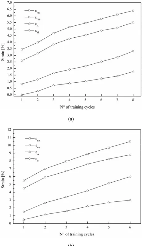
Fig. 7 report the measured values of εtot, εres, εA and εM versus the number of training
cycles, for the two values of training deformation; in particular, Fig.s 7(a) and 7(b) illustrate the results for εtr=3.5% and εtr=5.5%, respectively.
(a)
(b)
Fig. 7: εtot, εres, εA and εM versus the number of training cycles:
(a)
(b)
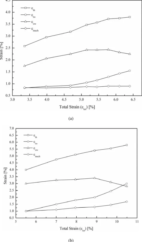
Fig. 8: εth, εtw, εow and εmech versus the total strain εtot:
As expected, both figures clearly show that all the deformations increases with increasing the number of training cycles as a consequence of the formation of a dislocation structure, which is confirmed by the increase in the plastic strain εpl, i.e. the
deformation in austenitic condition εA. In particular, Figure 7(a) shows that εtot increases
from 3.5 %, at the first training cycle, to 6.4% after eight cycles, whereas εpl raises from
0 to 1.8%. As expected Figure 7(b), which is relative to a training deformation of 5.5%, shows higher values of both εtot and εpl, which increase from 5.5% to 10.5% and from
0.5% to 3.0 %, respectively. As said before, the development of the plastic strain benefits the two way shape memory behaviour of the material. It is important to point out that in the measured εpl also the deformation due to the martensite stabilization is
computed.
Figs 7 show the measured values of the two-way strain, εtw, one-way strain, εow, thermal
recovery strain, εth, and mechanical recovery strain, εmech, versus the total strain εtot,
during the thermo-mechanical training; in particular, Fig. 8(a) and 8(b) are relative to a training deformation of 3.5% and 5.5%, respectively. Both figures show that the thermal recovery, εth, increases with increasing the total strain, with maximum values of 3.8%
and 5.8% for εtr=3.5% and εtr=5.5%, respectively; as the thermal recovery εth can be
regarded as εtw+εow (see Fig. 5), this result indicates that, in the investigated range, an
overall increase in the shape memory performances of the material when increasing the total strain in the investigated ranges as consequence of the developing of detwinned martensite and plastic strain. In fact, the graphs show that the two way strain increases with increasing the total deformation, for both training conditions, whereas an increase in the one way strain is observed in the first cycles.
The subsequent decrease of the one way strain with further increasing the total deformation can be attributed to the formation of a dislocation structure and stabilized martensite, which in turn benefit the two way shape memory performance of the material, as consequence of the establishment of a directional internal residual stress field and, consequently, cause a reduction of the one way recovery capability of the material, due to the smaller fraction of M→A transformation during thermal cycles (Liu et al. 1998, Liu 1999, Wada et al. 2005, Otsuka et al. 2005).
In particular, the curves in Fig. 8(a), which are relative to a training deformation εtr=3.5%, show an increase in εtw from 0.8% to 1.6%, and an increase in εow from 1.8%
to 2.4%, when εtot raises from 3.5 % to 5.8%, and a subsequent small decrease to 2.3%
with further increasing the total deformation. As shown in Fig. 8(b), the aforementioned effect is more evident for a training deformation of 5.5%, where εtw raises from 1.0% to
3.0%, whereas εow reaches a maximum value of 3.4%, when εtot is about 9%, and a
subsequent marked decrease to 2.8% is observed when εtot=10.5%. The graphs also
show a very small increase in the mechanical recovery εmech when εtr=3.5%, whereas a
marked increase is observed when εtr=5.5%. At each cycles more and more stabilized
martensite are not detwinned but deformed elastically; this causes the increase of the slope of the plateau during loading and the increase in the εmech upon unloading. This
effect is also qualitatively shown in Fig. 6(b) where a strong hardening of the material is observed when the thermo-mechanical cycles are carried out with a training deformation of 5.5%; because of the higher value of reached deformation, a more rapid stabilization effect, with respect to a training deformation of 3.5%, is observed, resulting also in higher value of εmech.
The two way shape memory strain of the material, obtained by a training deformation of 5.5%, was also measured under a fixed applied stress, as illustrated in Fig. 9. This investigation permits to understand the capability of the material to produce work during the TWSME cycle and to evaluate the modifications induced in the material behaviour by the applied stress. In fact, The production of work, in applications where the material is used as actuators, is obtained applying a resistance force that oppose itself to the shape recovery of the material.
The figure shows the measured hysteresis loops, two way strain versus temperature, in the case of stress free condition, together with those obtained by two fixed values of tensile stress, 50 and 100 MPa. As clearly shown εtw increases when increasing the
applied stress, from 3.1% to 3.6% and 4.2% under 50 MPa and 100 MPa, respectively. As can be seen, the external stress, applied in the same direction of the previous deformation, benefits the formation of further stabilised preferentially oriented martensite variants and, consequently, an increase in the εtw (Wada et al. 2005, Otsuka
et al. 2005).
The figure also shows, as expected, a systematic increase of the transformation temperatures as consequence of the applied stress, or rather the volume fraction of the
stabilised martensitic variants (Liu et al. 1998, Liu 1999, Wada et al. 2005, Otsuka et al. 2005).
In Fig. 10 the transformation temperatures, which were identified by using the slope line extension method, as function of the applied stress are shown. The linear increase in the transformation temperatures is an accordance with the well known Clausius-Clapeyron rule. In particular, as reported in the following, the dσ/dT is a characteristic constant of the material. In the investigated range, an increase of about 10 °C is observed for all transformation temperatures when the specimen is subjected to a tensile stress of 50 MPa, and an increase of about 15 °C is measured in the specimen under 100 MPa.
Fig. 10: Transformation temperatures as function of the applied stress
In many practical application the NiTi alloys are subjected to cycling by repeated heating and cooling; therefore the thermal stability of two way shape memory effect is an important issue to design and control smart sensors and actuators. In Fig. 11 the stability of two way shape memory effect, for the specimen obtained by a training deformation of 5.5%, is shown versus the number of thermal cycles.
The material shows a degradation of εtw from about 3.1% to 2.1 % after 35 thermal
cycles; it seems that degradation occurs in two stages, in fact, εtw decreases rapidly in
the first 25 thermal cycles and then becomes stable with further increasing their number. In the first stage a rearrangement of the internal stress field seems to come until a new saturated state is reached at higher number of cycle. This behaviour is due to a partially relaxation of the stress field formed by the training process, leading to the difficulty to form the preferentially oriented martensite variants (Perkins 1973, Miyazaki et al. 1986).
C
HAPTER
3
L
ASER WELDING OF
N
I
T
I
A
LLOYS
:
M
ECHANICAL AND
S
HAPE
M
EMORY
B
EHAVIOUR
3.1
O
VERVIEWBecause of reduced manufacturing costs and improvements in product quality, the demand for NiTi alloys is expected to rise considerably in the near future. Unfortunately, due to the low workability of these materials with conventional machining processes (milling, turning and drilling), suitable joining and cutting techniques must be used to obtain devices and components with complex geometries. Furthermore, as described in the previous chapters, NiTi properties strongly depend on the production parameters; the modifications induced by the working processes, in terms of thermo-mechanical effects and chemical contaminations, have a strong influence on the functional behaviour of the material (Otsuka et al, 2005; Serneels, 1999). A deeper understanding of the modifications due to various working processes on the properties of these alloys, could be useful for developing new industrial applications. In this field, obtaining welded joints with similar mechanical and functional properties of the unwelded ones, could create new possibilities for the realization of complex shaped components. Welding NiTi to itself can be more easily
performed with respect to the welding with dissimilar metals (H. Wu Ming, 2001). A degradation in SE and SME is generally observed in the homologous weld joints together with a degradation in tensile strength and in the resistance to permanent deformation, due to the microstructural modifications induced in the welding zone (Beyer et al, 1986 and 1989; Schlossmacher et al, 1995 and 1997; Haas et al, 1999; Falvo et al, 2005). Joining NiTi alloys with dissimilar metals, and in particular with stainless steel (Wang, 1997), is very difficult due to the formation of brittle intermetallic compounds. Generally, these types of weld joints are made using a interlayer material (H. Wu Ming, 2001).
One of the main problems involved in the welding of NiTi alloys is the oxidation of the weld bead due to the high reactivity of the titanium; for this reason, the protection of the welding zone using inert gas (Tuissi et al, 1999, Falvo et al, 2005 and 2007; Schlossmacher et al, 1995 and 1997), such as helium or argon, is necessary together with an accurate cleaning of the weld zone to avoid chemical contaminations.
Another important aspect to be considered is the formation of cracks in the heat affected zone and molten zone in terms of hot and cold cracking (H. Wu Ming, 2001; Beyer et al, 1986; Falvo et al, 2005); this problem is more evident in the welding of Ti rich NiTi alloys.
The hot, or solidification, cracks sensibility of NiTi welded joints are mainly due to the presence of impurities with lower melting temperatures than the NiTi material. Solidification cracking occurs during the terminal stage of solidification, when grains are separated from one another by a small amount of liquid in the form of grain-boundary films (Weman, 2003). At this time, the weld metal can be rather weak and thus susceptible to cracking in the presence of tensile stresses/strains. The weld metal tends to contract during cooling because of solidification shrinkage and thermal contraction, so that tensile stresses/strains can be induced in the weld metal if it cannot contract freely during cooling, for instance in a highly restrained workpiece.
The cold cracking, instead, is caused by the residual stresses that are in the welding components as consequence of the thermal effects due to the welding and it occurs at temperatures close to the ambient temperature (Weman, 2003). In particular, if the material is embrittled by the welding, these residual stresses can cause the fracture of the joint. The embrittlement of the welded material can be attributed to the formation of
some chemical compounds that decrease the ductility of the joints, such as oxides, or to particular microstructures of the material formed during the cooling of the weld bead. These types of cracks are generally observed in the HAZ and in material characterized by a microstructure transformations that occur at low temperatures (Weman, 2003). Obviously, in a highly restrained workpiece, cold cracking appears more easily because the residual stresses are higher than in a free one.
The effects introduced by the welds on the martensitic transformation depend both on the microstructural state of the reference material and on the welding process parameters (Tuissi et al, 1999). Although significant efforts have been devoted to these aspects, not many studies concerning welding techniques for joining NiTi alloys are reported in literature (Beyer et al, 1986 and 1989; Ikai et al, 1996; Schlossmacher et al, 1995 and 1997; Haas et al, 1999; Tuissi et al, 1999; Falvo et al, 2005 and 2007; Shinoda et al, 1991; Nishikawa et al, 1982; Jackson et al, 1972; H. Wu Ming, 2001; Hirose et al, 1990).
In friction welding and resistance butt-welding (Beyer et al, 1986 and 1989; H. Wu Ming, 2001), the joint is under a great compression force during the welding process. This closes any possible grain boundary crack and leads to an outward extrusion of the fusion zone, so that oxidation is largely prevented. Using consumable filler metal could be helpful to reduce cracks formation and to increase the joint strength (H. Wu Ming, 2001; Weman, 2003). The major disadvantage of these methods are that the welding zones have to be trimmed due to the strong extrusion of matter, and that they are executed in ambient atmosphere.
Tungsten inert gas (TIG) welding(Ikai et al, 1996)generally causes a great degradation in the mechanical and functional properties of the joint due to an extended heat affected zone (HAZ) that reduces the applicability of this welding technique.
In the last few decades, laser technologies have reached a great importance in the field of mechanical processes due to the possibility to focus the energy of working in very small spots (Cary Howard et al, 2005). This processes minimizes the HAZ and permits to reduce the influence on the material properties. However, very few studies concerning laser welding of NiTi alloys are reported in literature (Schlossmacher et al, 1995 and 1997; Haas et al, 1999; Tuissi et al, 1999; Falvo et al, 2005 and 2007) in these
works, the properties of the welded joints was investigated in terms of mechanical and functional behaviour.
Generally, laser welding of NiTi alloys can be well performed using Nd:YAG andCO2
sources. A significant reduction of mechanical and functional properties are always observed in CO2 laser welded joints (Hirose et al, 1990; Tuissi et al, 1999) while
Nd:YAG source seems to be more useful for welding NiTi alloys preserving a good tensile strength and functional behaviour (Schlossmacher et al, 1995 and 1997; Haas et al, 1999; Falvo et al, 2005 and 2007). Furthermore, Nd:YAG source is suitable for welding low thickness components, due to its high precision and reduced HAZ moreover, an appropriate control of the process parameters ensures a good repeatability of the results (Geusic, 1964).
Most of the works concerning laser welding of NiTi alloys have investigated the effects of the process on the mechanical and functional properties in terms of SME and SE, while the TWSME of laser-welded joints was not investigated.
Finally, in the last years, some researches are investigating the possibility to obtain functionally graded NiTi alloys by different procedure. Laser welding could be a suitable method for obtaining this type of components welding together different NiTi alloys; this aspect is not investigated but can open new possibilities for innovative applications.
In this chapter, the results related to different investigations executed on laser welded NiTi sheets, realized in the Laser Laboratory of the ENEA Research Centre of Trisaia (Rotondella, MT), are reported.
In the first investigation, the joints are studied in terms of microstructure and uniaxial stress-strain curves; a measurement of the transformation temperature of base and welded material by Differential Scanning Calorimetry (DSC) tests is also executed. In the successive investigation, carried out after an optimization of the welding process, a proper thermal treatment was executed on both welded and base (reference) NiTi sheets and their shape memory behaviour is investigated by training procedure. In particular, the deformation mechanism involved in the material behaviour during repeated thermomechanical cycles was evaluated together with the incoming of the Two Way Shape Memory Effect (TWME) in the material. The effects of the number of training cycles and plastic strain on the hysteretic behaviour, strain versus temperature,
characteristic of the TWSME were also investigated. Finally, a systematic comparison of the results was carried out in order to evaluate the influence of the welding process on the material behaviour.
3.2
W
ELDING PROCESS
3.2.1 WELDING EQUIPMENT AND SPECIMENS PREPARATION
As said before, the major aspects involved in the welding of NiTi alloys, are the oxidation of the weld bead and the formation of hot cracks that drastically reduce the mechanical and functional properties of the welded joints. To avoid these failure events, a special experimental set-up was realized; in particular, a shielding chamber was built to protect the welding zone by oxidation, while a particular positioning system was utilized to reduce the formation of cracks, by applying a constant compression force on the welded zone.
The shielding system permits to create an inert atmosphere around the component to be welded by introducing in it Argon. The chamber is characterized, in the upper zone, by a polymeric (PMMA) glass through which laser beam was focalized on the sheets. The type of glass chosen is transparent to the Nd:YAG wavelength and so the power leak, due to refraction phenomena and glass heating, is minimized.
In Fig. 1, a model of the shielding chamber is reported. As can be seen, the argon input was executed in proximity of the glass to shielding it from damages due to molten bath squirts; instead, through a pipe realized in the base of the chamber, the protection of the lower welded zone was realized. From another pipe, the aspiration of the smokes was executed during welding in order to reduce the temperature in the chamber and, consequently, the soften of the glass and the overheating of the components. The chamber utilized in these experiments is shown in Fig. 2; even though a good result was obtained, an optimization of the system must be one of the future topics.
Fig. 1: CAD model of the shielding chamber
Fig. 2: Shielding chamber
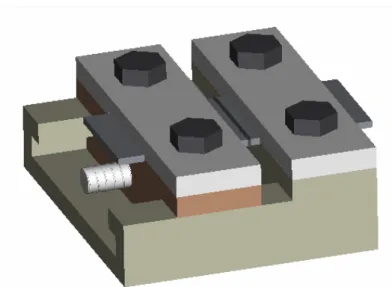
As said before, the crack sensibility of the NiTi alloys is an important aspect to be considered. In order to reduce the formation of cracks and, consequently, to obtain good performance of the welded joints, a special sledge, moved by a screw, was built; the system, showed in Fig. 3, permits the alignment of the components, with respect to the beam and to apply a constant compression force between them.
Argon input Glass
Aspiration of smoke
Fig. 3: Sledge used for alignment and compression of NiTi sheets
The system was characterized by two components coupled by a prismatic guide; the NiTi sheets are moved and compressed together by the screw, while a cup spring, mounted equiaxially, is used to maintain constant the force during the fusion of the material. This force closes any possible grain boundary cracks and leads to an outward extrusion of the fusion zone, so that oxidation is also better prevented. Furthermore, the spring permits the contraction of the sheets during welding reducing the cold cracking problem.
A preliminary optimization of the welding parameters, in terms of welding speed and laser beam power, was executed in order to define their better values; however, a more accurate study on the influence of the different parameters with respect to the quality of the joints is necessary.
In Fig. 4, some examples of weld cracks due to incorrect restraining of the sheets are reported.
Early experiments have showed the difficulties to weld NiTi alloys without take in account the important aspects related to the oxidation of the joints, the crack sensibility and the weld parameters.
Fig. 4: Cracks observed in some NiTi welded joints
In Fig. 5, instead , an example of gas pore observed in some joints is shown; this is probably due to a prolonged heating time that permits the intrusion of harmful elements (O, H or N) in the weld bead (Chen, 2005). The presence of these elements is very dangerous because they can form chemical compounds that make the joint very brittle with a consequent significant increasing of the cold cracking in the welded material. The welding process was carried out using a Nd:YAG laser source (HAASHL2006D, 2 kW), operating in continuous mode; the welding parameters and the path of the laser beam can be set by a personal computer. Different welding experiments were carried out using values of the beam power in the range of 600-1000 W and of welding speed in the range of 1000 and 1600 mm/min; the focusing of the laser been was always executed on the surface of the component.