Department of Civil, Chemical and Environmental Engineering
Polytechnic School, University of Genoa, Italy
Innovative Tools For Planning, Analysis,
and Management of UAV Photogrammetric Surveys
Daniele Passoni
ANALYSIS
,
AND MANAGEMENT OF UAV
PHOTOGRAMMETRIC SURVEYS
B
Y
D
ANIELE
P
ASSONI
Dissertation discussed in partial fulfillment of the requirements for the Degree of
DOCTOR OF PHILOSOPHY
Civil, Chemical and Environmental Engineering
curriculum in Fluid Dynamics and Environmental Engineering,
Department of Civil, Chemical and Environmental Engineering, University of Genoa, Italy
Adviser(s):
Prof. Domenico Sguerso
Department of Civil, Chemical and Environmental Engineering , University of Genoa
External Reviewers:
Prof. Antonio M. G. Tommaselli
Departamento de Cartografia, Universidade Estadual Paulista Júlio de Mesquita Filho
Prof. Gianfranco Forlani – Department of Civil and Environmental Engineering and Architecture, University of Parma
Examination Committee:
Prof. Gianfranco Forlani – Department of Engineering and Architecture, University of Parma Prof. Vittorio Casella – Department of Civil Engineering and Architecture, University of Pavia
Prof. Andrea Mazzino – Department of Civil, Chemical and Environmental Engineering, University of Genoa
Ph.D. program in Civil, Chemical and Environmental Engineering
Curriculum in Fluid Dynamics and Environmental Engineering
Cycle XXIX
Acknowledgements
The Unmanned Aerial System (UAV) is widely used in the photogrammetric surveys both for structures and small areas. The geomatics approach, for the several applications where the 3D modeling is required, focuses the attention on the metric quality of the final products of the survey. As widely known, the quality of results derives from the quality of images acquisition phase, which needs an accurate planning phase. Actually, the planning phase is typically managed using dedicated tools, adapted from the traditional aerial-photogrammetric flight plan. Unfortunately, UAV flight has features completely different from the traditional one, hence the use of UAV for photogrammetric applications today requires a growth in the planning knowledge.
The basic idea of the present research work is to provide a tool for planning a photogrammetric survey with UAV, called “Unmanned Photogrammetric Office” (U.Ph.O.), that considers the morphology of the object, the effective visibility of its surface, in the respect of the metric precisions. The usual planning tools require the classical parameters of a photogrammetric planning: flight distance from the surface, images overlaps and geometric parameters of the camera. The created “Office suite” U.Ph.O. allows a realistic planning of a photogrammetric survey, requiring additionally an approximate knowledge of the Digital Surface Model (DSM) and the attitude parameters, potentially changing along the route. The planning products will be the realistic overlapping of the images, the Ground Sample Distance (GSD) and the precision on each pixel taking into account the real geometry.
The different tested procedures, the solution proposed to estimates the realistic precisions in the particular case of UAV surveys and the obtained results, are described in this thesis work, with an overview on the recently development of UAV surveys and technologies related to them.
INDEX
INTRODUCTION ... 7
1. UNMANNED AERIAL VEHICLES ... 11
1.1 UAV Classification ... 13
1.1.1 Fixed-Wing UAV ... 13
1.1.2 Rotary-Wing UAV ... 13
1.2 UAV Components and Sensors ... 15
1.3 Current International and Italian Regulations ... 16
2. THE SURVEYS FROM UAV ... 21
2.1 Different Fields of Applications ... 21
2.1.1 Intelligence, Surveillance, Search-and-rescue ... 22
2.1.2 Inspection ... 23
2.1.3 Cultural Heritage and Archeological Surveys ... 23
2.1.4 Traditional Surveying and Cadastral Applications ... 23
2.1.5 Precision Farming, Forestry and Environmental Applications ... 24
2.2 Survey Sensors ... 24
3. UAV PHOTOGRAMMETRY ... 27
3.1 Characteristics of UAV Photogrammetry ... 27
3.2 Theoretical bases of photogrammetry ... 28
3.2.1 The basic principle of photogrammetry ... 28
3.2.2 Image Acquisition Phase ... 30
3.2.3 Image Orientation ... 33
3.2.4 Outputs of the Photogrammetric Survey ... 37
3.3 Photogrammetry and Computer Vision ... 38
4. THE PRECISION IN PHOTOGRAMMETRIC SURVEYS ... 41
4.1 Error Theory ... 41
4.2 The Estimation of a Priori Precision in UAV Photogrammetry ... 43
4.2.1 The Model of Classical Photogrammetry ... 44
4.2.2 The Terrestrial Close-Range Model ... 45
5. THE U.PH.O. PROJECT ... 49
5.1 A review of current UAV Flight Planning Software ... 49
5.2 The Aim of the U.Ph.O. Project ... 54
5.3 The Planning Module ... 55
5.4 The Analysis Module ... 62
6. APPLICATION TO A CASE STUDY AND VALIDATION ... 65
6.1 Case Study “Belvedere Glacier” ... 65
6.2 Planning of the Survey for the Case Study ... 65
6.3 Case Study “Castle of Casalbagliano” ... 88
6.4 Analysis of the results and validation ... 90
CONCLUSIONS AND PERSPECTIVE ... 93
INDEX OF FIGURES
Figure 1-1 Fixed-wing UAV ... 13
Figure 1-2 Rotary-wing drone ... 14
Figure 2-1 List of UAS civil and commercial applications (European Commission, 2007) ... 21
Figure 3-1 Central projection model ... 29
Figure 3-2 Basic principle of stereo-photogrammetry ... 29
Figure 3-3 Flight plan schema for flat ground ... 31
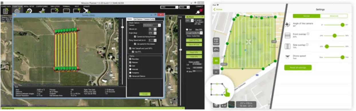
Figure 3-4 GCS software for photogrammetric flight plans: Mission Planner on the left and pix4dcapture on the right ... 33
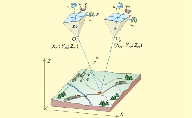
Figure 3-5 Parameters needed for the external orientation of a model composed by two frames (Cannarozzo et al., 2012) ... 34
Figure 3-6 Principle of Bundle Adjustment method (from Kraus, 1993) ... 36
Figure 3-7 Descriptor vector in the matching. ... 39
Figure 4-1 Imaging configuration normal (left image) and convergent (right image) ... 43
Figure 4-2 Stereo normal case, standard deviation evaluations ... 44
Figure 4-3 Representation of the sparse matrix A. ... 46
Figure 5-1 Graphical interface of Mission Planner ... 50
Figure 5-2 The planning tool of QGroundControl sw ... 51
Figure 5-3 The navigation tool of QGroundControl sw ... 51
Figure 5-4 Photogrammetric flight path with Terrain-following mode ... 52
Figure 5-5 Photogrammetric flight plan in Pix4Dcapture ... 53
Figure 5-6 Photogrammetric flight plan in DJI GS pro ... 54
Figure 5-7 Workflow of U.Ph.O. planning module ... 56
Figure 5-8 interface of the tool that reports the estimated flight parameters ... 57
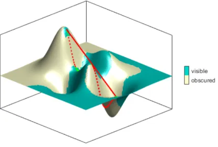
Figure 5-9 Line of sight algorithm ... 58
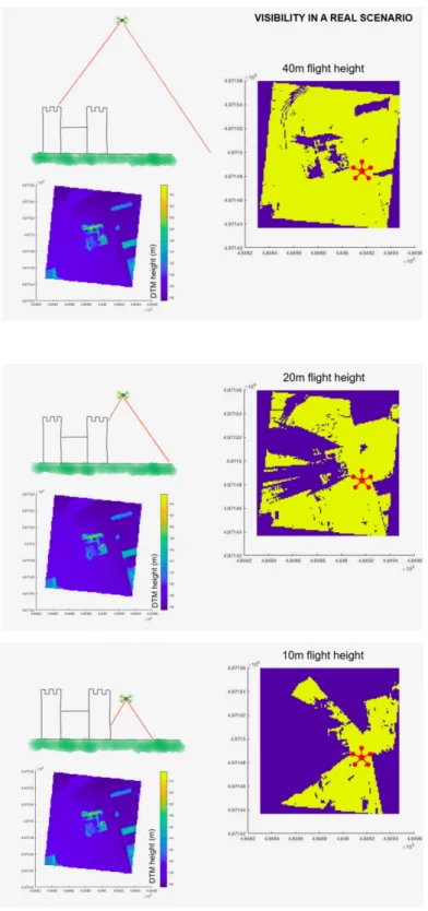
Figure 5-10 Visibility map changes as a function of camera height above ground ... 59
Figure 5-11 Overlap map and terrain expected coverage ... 60
Figure 5-12 Maps of DEM and standard deviations along Z computed with different approaches [m] . 61 Figure 5-13 Workflow of the U.Ph.O. module of analysis ... 62
Figure 6-1 the Belvedere Glacier ... 65
Figure 6-2 Selection of the survey area ... 66
Figure 6-3 Calculated projection centers ... 67
Figure 6-4 Map of visibility and overlapping ... 68
Figure 6-6 Map of the expected precisions [m] for the x-coordinate (figure on the left), for the y-coordinate (figure in the center) and for the z-y-coordinate (figure on the right) calculated using the rigorous
method ... 69
Figure 6-7 Precision X expected with rigorous method and overlapping 60%-30%: 2D and 3D representations with GCPs in different configurations - scale bar from 0m to 0.5m ... 72
Figure 6-8 Precision X expected with rigorous method and overlapping 60%-60%: 2D and 3D representations with GCPs in different configurations - scale bar from 0m to 0.25m ... 73
Figure 6-9 Precision X expected with rigorous method and overlapping 80%-60%: 2D and 3D representations with GCPs in different configurations - scale bar from 0m to 0.15m ... 74
Figure 6-10 Precision X expected with rigorous method and overlapping 80%-80%: 2D and 3D representations with GCPs in different configurations - scale bar from 0m to 0.10m ... 75
Figure 6-11 Precision Y expected with rigorous method and overlapping 60%-30%: 2D and 3D representations with GCPs in different configurations - scale bar from 0m to 0.5m ... 76
Figure 6-12 Precision Y expected with rigorous method and overlapping 60%-60%: 2D and 3D representations with GCPs in different configurations - scale bar from 0m to 0.25m ... 77
Figure 6-13 Precision Y expected with rigorous method and overlapping 80%-60%: 2D and 3D representations with GCPs in different configurations - scale bar from 0m to 0.15m ... 78
Figure 6-14 Precision Y expected with rigorous method and overlapping 80%-80%: 2D and 3D representations with GCPs in different configurations - scale bar from 0m to 0.10m ... 79
Figure 6-15 Precision Z expected with rigorous method and overlapping 60%-30%: 2D and 3D representations with GCPs in different configurations - scale bar from 0m to 0.5m ... 80
Figure 6-16 Precision Z expected with rigorous method and overlapping 60%-60%: 2D and 3D representations with GCPs in different configurations - scale bar from 0m to 0.25m ... 81
Figure 6-17 Precision Z expected with rigorous method and overlapping 80%-60%: 2D and 3D representations with GCPs in different configurations - scale bar from 0m to 0.15m ... 82
Figure 6-18: Precision Z expected with rigorous method and overlapping 80%-80%: 2D and 3D representations with GCPs in different configurations - scale bar from 0m to 0.10m ... 83
Figure 6-19 The Castle of Casalbagliano in its 3D reconstruction ... 88
Figure 6-20 The position of GCPs and Check Points (CPs) ... 89
Figure 6-21 Camera location of the nadiral survey (black dots) and image overlap (colour bar) ... 90
INDEX OF TABLES
Table 1-1 Features of aerial, close range and UAV Photogrammetry (Eisenbeiss, 2009) ... 12
Table 1-2 UAS categories (van Blyenburgh, 2011) ... 14
Table 1-3 ENAC requirements for the use of RPAS ... 19
Table 2-1 Sensors and field of application ... 26
Table 6-1 Analyzed Combinations ... 70
Table 6-2 statistics of precision X expected with rigorous method ... 85
Table 6-3 statistics of precision Y expected with rigorous method ... 86
INTRODUCTION
In the last years the use of UAV (Unmanned Aerial Vehicles) is increasingly catching on in the field of photogrammetry. According to the definition of UVS International (Unmanned Vehicle System), a UAV is a generic aircraft planned to operate without any human pilot on board (http://www.uvs-international.org). The terms “UAV” and “drone” are the most used ones in the geomatic applications, but there are also other terms, like “RPV (Remotely Piloted Vehicle)” or in Italian APR (Aeromobili a Pilotaggio Remoto), which are used according to the kind of aircraft, the propulsion system, the altitude and automation level of the vehicle. The term UAS (Unmanned Aerial System) defines the totality of aerial aircraft and the Ground Control Station (GCS). Ground control stations are hardware and software devices which have the task to monitor and command the aircraft. Therefore, the GCS is a key system component, as it provides the interface to the pilot: any change in the itinerary, any possible mistake of the aircraft and, in general, any output of the on-board sensors is sent to the station and displayed through the station itself. Furthermore, GCS is an essential tool not only for the autonomous guide of drones, but also because it often provides the software needed for the planning of a survey flight.
UAV technology was originally developed for military purposes and applications and it is still widely used in this field. Its first use in the geomatic area dates back some decades ago, but only in the last 10-15 years UAV systems have become a common tool in the acquisition of territorial data. In particular, photogrammetry by drone has opened new opportunities in this field, introducing a low-cost alternative to the classical photogrammetry. The fast spread of UAV systems is due to the birth of new kinds of low-cost aircrafts, digital cameras and other sensors in combination with GNSS/INS systems (Global Navigation Satellite Systems / Internal Navigation System), which are essential for the georeferencing of surveys.
The currently available UAVs are different in dimension, shape, flight duration and altitude and load capacity. The attention of most operators is, for photogrammetric survey purposes, paid to mini and macro UAV, i.e. those with a weight lower than 25 kg. According to the Italian law (ENAC, 2018), these categories are further divided into three types: the harmless Remotely Piloted Aircraft System (RPAS), with a take-off weight lower than 300 g and have to be declared as RPAS by ENAC; RPAS Very Light (VL) with a take-off weight between 300 g and 4 kg and RPAS Light (L) with a take-off weight between 4 kg and 25 kg.
These RPAS have a flight duration between some minutes and just over 1 hour, but, in any case, the legislation allows only a limited operating distance and flight altitude.
There are two specific categories of aircrafts: fixed-wing and multirotor aircrafts, and any of them has different features, advantages and uses (Colomina, I., and Molina, P. 2014; Padua, L., et al. 2017). The dimension and orography characteristics of the covered area, the ground resolution of images (expressed by the so called Ground Sample Distance or GSD, directly connected to the flight altitude and the camera focal length) and the features of the take-off and landing area are the elements to take into account in order to choose between these two categories of aircraft. Fixed-wing RPAS are used for areas with a size between 1 and 10 km2, for Ground Sample Distance (GSD) higher than 3-5 cm and need a flat take-off and landing area of some tens of square meters. Multirotor aircrafts are employed in areas with a dimension between 10000 m2 and 1 km2, for Ground Sample Distance (GSD) between some millimeters and 3 cm and have no particular requirements about the take-off and landing area.
In both cases the flight planning is guaranteed by the on-board presence of the Global Navigation Satellite System (GNSS) receiver, able to keep the pre-planned route. A more or less sophisticated self-piloting system allows different autonomy levels of flight in the most delicate take-off and landing phases and some RPAS of the latest generation are finally equipped with anti-collision telemetric systems in order to secure a minimum distance from obstacles during the shooting phase (Accardo, D., et al. 2013).
The low-cost and light-weight sensors, suitable to be carried by a VL-RPAS or L-RPAS, has considerably developed in the recent years and the market is now offering a lot of solutions for several passive and active sensors. Among passive sensors it is possible to distinguish the so called RGB cameras, sensitive to the visual part of the electromagnetic spectrum (from about 400 to 700 nm), NIR or CIR cameras, sensitive to the infrared part of the spectrum (from 700 to 1000 nm for NIR sensors, from 400 to 1000 nm for CIR sensors), thermal cameras (whose sensors are sensitive to the spectrum components between about 5000 and 14000 nm) and, finally, multispectral and hyperspectral cameras, that generally assure the acquisition of a variable amount of spectrum components that depends on the amount of registration channels. Among active sensors, a particular case is represented by LIDAR that determines georeferenced point clouds, which the reflectance of the surface hit by the laser pulse is associated to. These systems are used in several applications like i.e. the restoration of the cultural heritage, the evaluation of the growth of arboreal vegetation, the assessment of the biomass and to acquire the morphology of the terrain for hydraulic studies (Wallace, L., et al. 2014; Malinowski, R., 2016; Bareth, G., et al. 2016). Because of their high costs, these products are not yet widely used.
All sensors have a weight between few grams (Action Cam) and some kilograms (Lidar) and are suitable to be carried by most types of RPAS. Costs are also considerably variable: except for LIDARs, which are still very expensive, with costs in excess of some tens of thousands of euro, the cameras equipped optic sensor can have a cost between few tens of euro (RGB Action Cam cameras) and about 10,000 euro for multispectral cameras (Nebiker, S., et al. 2016).
UAV have found their space in several application fields. Video and photo documentation, security and monitoring, precision agriculture and territory survey, intelligence, surveillance and reconnaissance, inspection, cultural heritage and archaeological survey, traditional surveying and cadastral applications, are only some of the numerous fields, in which this tool is widely used. The scientific community has enthusiastically embraced the potentialities expressed by UAV and has worked hard to develop them as tools of metric measurement.
A great commitment has been taken in the technological development of both on-board sensors for navigation and for survey sensors.
As it always happens when a new technology is incoming, it is necessary to adapt old and consolidated operating methods to the new instruments. For this reason, photogrammetry software had to take on this new challenge abandoning consolidated procedures and beginning to interact with new processes particularly oriented on quick and automatic elaborations phase, strongly connected with the technology of the Computer Vision.
The aeronautic industry has spent a lot of energy in the last decade in the production of more and more performing drones, easy to be piloted even by less expert users. The technological development has
increased the ease and the security in their usage. The avionic research has produced models able to fly higher and higher and more and more faraway. The task of the scientific research in geomatics field, and of this thesis work in particular, is instead to help the drone users to deepen the knowledge and competences, so that they could better understand the applicative potentialities of drones in several fields, with particular attention to the metric aspects.
The present work is organized starting from the history and development of the Unmanned Aerial Vehicles, together with the essential characteristics and Italian and European norms and regulations that influence their functioning and governability respectively (chapter 1). In chapter 2, different fields of applications of UAV will be described (like i.e. intelligence, surveillance and reconnaissance, inspection, cultural heritage and archaeological survey, traditional surveying and cadastral applications, but also precision farming, forestry and environmental applications) in order to identify their strong points and critical issues. In chapter 3 the basic principles of photogrammetry and of the use of UAV in this field, to obtain metric information about the survey object, will be discussed. However, the concept of “metric information” of a survey will be defined and deepened in the following chapter (chapter 4), whose goal is not only to recognize its capacity of recovering the dimensions of the observed objects, but also the ability to determine the precision of the registered metric information, both a priori and a posteriori. Following this perspective, after presenting the current situation of the survey by drone giving basic technical information to understand its complexity and potentialities, in chapter 5 an a priori precision estimate method will be provided. It will be proposed like a useful practice to apply to surveys by means of real and concrete tools. Before dealing with this topic, it is important to know the interface between man and machine in the surveys by UAV and to learn how the planning of a survey takes place in practice. The tools presented, starting from chapter 5, are collected in an "office suite", called U.Ph.O. (Unmanned Photogrammetric Office), realized in Matlab environment. The proposed solutions are the result of an accurate study of estimation methods of the expected precisions for a survey by drone, starting from the consolidated basis of aerial and close-range terrestrial survey. The “Office suite” proposed permits to design a “realistic” survey planning of the navigation route in respect of the a priori DSM, both providing standard solutions and predicting the expected precisions. The starting points are: the a priori information about required precisions and/or the so called Ground Pixel Dimensions (GSD), the overlap of the projected images on the ground/object (in the two directions, longitudinal and transversal on the UAV navigation route), an approximate knowledge of the DSM and the desired attitude parameters, potentially changing along the route. The basic idea of the present research work is to considers the morphology of the object, the effective visibility of its surface, in the respect of the metric precisions rigorously evaluated with a least square simulation. Thus, the created “Office suite” U.Ph.O. allows a realistic planning of a photogrammetric survey with overlapping of the projection of the images covering the DSM, their Ground Sample Distances (GSD) and the expected precision on each object pixel, taking into account the real visibility by the images. This work is aimed to provide both the theoretical instruments to make a good planning of a survey with an evaluation of the expected precisions and the practical tools to support the everyday practice of metric survey by UAV.
The U.Ph.O. tool is made up with a second module for the analysis phase of the survey campaigns, useful to verify the obtained coverings on DSM coming from the frames, checks the absence of holes and estimates the accuracy of the survey. The analysis tool uses the telemetry recorded by the drone during the flight or the External Orientation parameters obtained from expeditious processing of the images as its starting data.
In chapter 6, the U.Ph.O. Office suite will be applied to two case studies. The case study of the Belvedere glacier will show the possibility to design different scenarios to better choose the best solution for each specific case, the case study of the Castle of Casalbagliano (Fagandini, R., et al. 2017) will be shown how this survey has been planned before the realization and analysed after the performance of the flight. Considering that the case study is rich of information coming from additional data set, it can be used to show the use of U.Ph.O. and also to validate its reliability.
The different tested procedures, the solution proposed to estimates the realistic precisions in the particular case of UAV surveys and the obtained results, are described in this thesis work and resumed in the conclusions and perspectives, with an overview on the recently development of UAV surveys and technologies related to them. Some operative good practice criteria has been suggested, coming from the analysis of different configurations simulated in two real scenarios. Finally main steps to optimize the Office suite tools U.Ph.O. and which future developments are proposed.
1. UNMANNED AERIAL VEHICLES
The acronimous UAV (Unmanned Aerial Vehicle) represent the much more popular word “drone”. In order to better understand the potentialities and the problems related to a survey performed through Unmanned Aerial Vehicles, in this first chapter the history of their development and the features of the UAVs available on the market, together with the essential characteristics that influence their functioning will be described. Finally, the regulations governing their use on the legislative front both in Italy and in Europe will be introduced.
The diffusion of UAVs has been incredibly fast in the last years and they are becoming part not only of everyday language, but also of collective imagination. This technology, created for military purposes, has rapidly found its place in the recreational and professional fields for video recording, photography and photogrammetric surveys; this last one field is particularly treated in this thesis. It is not uncommon that a technology originally invented for military purposes becomes so useful in the civil society. The Global Navigation Satellite System (GNSS), the optical satellites and the Synthetic Aperture Radar (SAR) are known examples of the Geomatics’field and the so-called UAVs are not an exception.
Due to its diffusion and numerous fields of application, we do not have a “unique” and shared definition of this technology yet. In the 1990s, the term was changed to UAV and, a decade later, the Federal Aviation Administration (FAA) of the US Department of Transportation has introduced the generic term UAS (Unmanned Aircraft System): it underlines that the whole system is composed by an Unmanned Aircraft (UA) plus a Control System (CS) -usually a Ground Control Station (GCS)- and a communication data link between the UA and the GCS (Eisenbeiss, 2009).
Its definition is now well known: a UAV is a powered aerial vehicle, which does not need a human operator physically onboard; it can fly autonomously or be remotely piloted and it uses aerodynamic forces to provide vehicle lift. In particular, UAVs can be remotely controlled, semi–autonomous, autonomous or have a combination of these capabilities. In many cases, the crew responsible for a UAV is larger than that of a conventional aircraft (Everaerts, 2008).
The recent terminology "UAV Photogrammetry” (Everaerts, 2008) describes a photogrammetric platform, equipped with a photogrammetric measurement system with RGB (Red, Green, Blue) camera, airborne LiDAR system (Light Detection and Ranging), thermal and multispectral systems or a combination thereof. The definition of a “UAV Photogrammetry” opens new scenarios and developments both for the aerial and for the close-range photogrammetry. It’s in this perspective, as it will be shown in the following chapters, that the development of new shooting sensors and software for image processing related to Computer Vision (CV) is to be found. In Table 1.1 Eisenbeiss (2009) has resumed the main characteristics for different photogrammetric phases, for the different kind of acquisition: aerial, close range and UAV.
Table -1 Features of aerial, close range and UAV Photogrammetry (Eisenbeiss, 2009)
Aerial Close Range UAV
Planning (semi) automatic Manual Automatic/manual
Data
acquisition/Flight Assisted/manual Autonomous/assisted/manual Autonomous/assisted/manual
Size of the area km2 mm2– m2 m2– km2
Image
resolution/GSD cm– m mm– dm mm– m
Distance to the
object 100 m– 10 km cm– 300 m m – km
Orientation Normal case, recently also oblique Normal/oblique Normal/oblique
Absolute accuracy of the initial orientation values cm– dm mm– m cm– 10 m Image block size/number of scan 10 – 1000 1 – 500 1 – 1000 Special applications (examples) and features
Aerial view large scale area (mapping, forestry, glaciology, 3D-ciry,
modelling, etc.)
Terrestrial view small-scale areas and objects
(archaeological documentation, 3D modelling of buildings and
objects), architectural and industrial Photogrammetry
Aerial view small and large-scale areas (archaeological
documentation, 3D modelling of buildings and
objects), applications in inaccessible areas and dangerous objects, real-rime
applications (monitoring)
The Table 1.1 shows the comparison between UAV photogrammetry, traditional aerial photogrammetry (for example from an airplane) and Close Range Photogrammetry (CRP), where images are collected from ground. UAV photogrammetry offers the possibility to perform aerial surveys in close range, it is a low-cost alternative to the traditional manned aerial photogrammetry and can be used for real-time applications (e.g. monitoring).
1.1
UAV Classification
The classification of UAV includes a wide range of aircrafts with different features and technologies: according to these and other parameters a UAV can be suitable to an application and unsuitable for the other ones. There are several possible classifications of UAV:
• powered or unpowered;
• flexible, fixed or rotating wing;
• single, coaxial, quad-rotor or multi-rotor;
• lighter than air (balloons) or heavier than air (kites, drones, etc.).
Among all these possible classifications, the most obvious one, mostly influencing the usage modality and fields applications, is the distinction between “Fixed-wing” and “Rotary-wing”.
Fixed-Wing UAV
Fixed-wing UAVs (Figure 1-1) are capable of flight thanks to the wings that generate lift, produced by the vehicle’s forward airspeed and the shape of the wings themselves. These drones are ideal for longer missions, generally when the area to be mapped is very large. Moreover, some models with wingspans greater than 2m may also be suitable for carrying large payloads, such as high resolution DSLR (Digital Single Lens Reflex) cameras, LiDAR (Light Imaging Detection and Ranging), gas and thermal sensors. On the other hand, fixed-wing drones require a flat take-off and landing strip of some tens of square meters.
Figure 1-1 Fixed-wing UAV
Rotary-Wing UAV
Rotary-wing UAVs, commonly drones (Figure 1-2), use lift generated by wings, called rotary wings or rotor blades, that revolve around a mast. These devices differ from the previous ones, because generally they have less autonomy. Their dimensions should be significantly increased in order to be able to support such a payload. On the other hand, they are cheaper than fixed-wing drones, because they have a huge spread into the hobby market that brings a dramatic cost reduction of their components. In addition, they are more agile than fixed-wing drones and can perform vertical take-off, which is a great advantage in harsh environments.
Figure 1-2 Rotary-wing drone
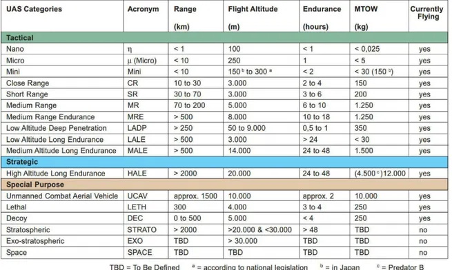
According to dimensions, Maximum Take-Off Weight (MTOW), engine, payload, maximum reachable distance and flight height, UAS can be classified as follows:
micro or mini;
close, short, medium or long range; low, medium or high altitude.
A classification based on the above features is adopted by the UVS International (Unmanned Vehicle System International). Born in 1995 with the name EURO UVS, UVS International is since year 2000 «a non-profit association [...] which represents manufacturers of Remotely Piloted Systems (RPS), related subsystems and critical components and associated equipment, as well as companies supplying services with or for RPS, research organizations and academia» (www.uvs-international.org). In particular, UVS International subdivides UAS into three main groups, namely tactical, strategic and special purpose, shown in Table 1.2.
1.2
UAV Components and Sensors
Even if UAVs belong to different classes, they have all similar components and tools, which are indispensable for the flight and the autonomous navigation.
In the following section, we will analyze each component of the drone explaining its role inside the system.
- Frame
The frame is the skeleton of the UAV. The essential characteristics of a frame are lightness and robustness. The frame shall have all the aeronautical features for the flight and be able to contain the navigation tools and the survey sensors.
- Motors and propellers
The motors and propellers provide thrust to the fixed-wing, and lift and direction to the multicopter; they are very delicate parts of the drone to be dimensioned, since they must act accordingly to the payloads and the battery capacity. All the latest drones use electric brushless motors which are more efficient, more reliable and quieter than brushed ones. There are also drones with combustion or turbine engines, but they are not suitable to survey and, for this reason, they will be not mentioned in the present work.
- Electronic Speed Control (ESCs)
The ESC is an electronic circuit with the purpose of varying the motor’s speed, its direction and, possibly, to act as a dynamic brake. Its main function is to convert DC battery power into 3-phase AC for driving brushless motors. The control of the speed of rotation of the propellers is an important factor for the flight, being able to manage this parameter with high precision allows stable flights and high manoeuvrability of the aircraft.
- Flight controller
The flight controller is the computational centre of the drone, it elaborates inputs from the receiver, GNSS module, battery monitor, IMU and other on-board sensors. Using this information, it controls motor speeds through the ESCs, it triggers the camera and monitors autopilots and waypoints.
- Battery
LiPo batteries provide power, they can vary both in number of cells (2S-6S) and in capacity (mAh). In all cases, we need to pay a lot of attention to the battery choice, because the drone must be able to work in different regions and places, where the temperature can be very high or reach negative values. The high or low temperatures affect negatively the battery capacity by decreasing it up to 50% of its initial value.
The radio receiver allows the drone to communicate with the ground controller, that can be both a ground station and a human pilot. In most cases, the drone can be controlled also by a dedicated software using the given waypoints, elaborate the drone’s trajectory, optimizing the chosen parameters. Radio frequencies, traditionally used in the model aircraft building field, have been recently substituted by the common frequencies of Wi-Fi transmissions (2.4GHz in Europe and 5GHz in the USA).
- GNSS receiver
The GNSS receiver is a key module to provide some fundamental localization parameters, such as latitude, longitude, elevation. Position data are necessary to execute all the autonomous flight modes and for the waypoint navigation.
- Ground station
In general, a ground station is a computer or a dedicated hardware that runs some software able to communicate with the drone by means of radio waves. It is able to control the drone navigation following a specific algorithm, like the waypoint navigation. In recent years some applications performing this same task from tablet or smartphone have been developed too.
- Gimbal
The gimbal is a motor-powered camera support that is usually placed under the frame. It contains the camera and, through the servo-motors, it guarantees to maintain pointing according to plan. It is usually realized through physical mechanisms and can be replaced to some extent by the image electronic stabilization.
- IMU
The Inertial Measurement Unit (IMU) uses a combination of sensors, usually a gyroscope, an accelerometer and a magnetometer, to keep tracks of the drone’s specific force, angular rate and magnetic field surrounding the body.
- Cameras and sensors
Drones can be equipped with a photogrammetric measurement system, including thermal, infrared or RGB (Red, Green, Blue) camera systems, airborne LiDAR systems or a combination thereof.
1.3
Current International and Italian Regulations
The number of UAV users for “specialized operations” is constantly increasing. Its users are professionals dealing with architectonic, artistic or technical cadastral survey, but also governmental authorities involved with internal security matters (e.g. municipal and national police, anti-terrorist squads, fire brigades, forest fire fighters, coast guards, civil defense, environmental protection agencies) have shown great interest in the use of UAS. Large corporate entities (e.g. electric grid operators, pipeline network operators, railway operators, oil companies) have also started to realize how much UAS can benefit
their corporate operations (van Blyenburgh, 2014). If on the one hand the increasing number of users has encouraged the technological development of more and more performing drones and highly automated software, on the other it has stressed the need of a legislative regulation able to guarantee public safety and security. It is important to remember that the drones, the more so if equipped with heavy payloads, are real aircrafts that can fly over “critical areas”, such as residential areas, crowded places or “sensitive” infrastructures (highways, rail system…).
The first example of operating regulation in the world was approved by the Australian Civil Aviation Safety Authority (CASA) in 2002. This document sanctions that anyone who is interested in letting UAS fly for professional purposes needs to have an operator certificate guaranteeing the proper education of the pilot and the suitability of his drones. The Federal Aviation Administration (FAA) of the United States also developed a complete plan to insert UAS in the National Airspace System.
Currently (epoch when the present thesis has been written i.e. 2018), in the European Union (EU) the regulatory responsibility for civil UAS with a Maximum Take-Off Weight (MTOW) of more than 150 kg lays with the European Aviation Safety Agency (EASA) and for those with a MTOW of less than 150 kg with the National Aviation Authorities (NAAs). Various initial national regulations related to the operation of civil UAS are now in place (Austria, Czech Republic, Denmark, France, Germany, Ireland, Italy, Sweden, United Kingdom), are about to enter into force (Belgium, Finland, Lithuania, Norway, Switzerland), or are in progress (Malta, The Netherlands, Spain). In practically all cases, at the moment flight operations are taking place within visual line-of-sight, at a flight altitude of less than 150 m above ground level with UAS characterized by a MTOW of less than 25 kg. A significant amount of European NAAs facilitate UAS operations by granting Permits-To-Fly on a case-by-case basis (van Blyenburgh, 2014). These regulations principally concern light UAS and they are not harmonized on a pan-European level, even if efforts towards this direction are in place: indeed, in June 2013, the European RPAS Steering Group (ERSG) released the "Roadmap for the integration of civil Remotely-Piloted Aircraft Systems into the European Aviation System". This report comprehends detailed proposals and a schedule for a regulatory approach, a strategic research plan and a study on the societal impact of UAS (ERSG, 2013). Furthermore, the Joint Authorities for Rulemaking on Unmanned Systems (JARUS), which federates the NAAs of 22 countries, as well as EASA and EUROCONTROL, published its first certification specification (CS-LURS) in November 2013 (JARUS, 2013). JARUS intent is to eliminate the need for each country to write their own requirements and to promote the reciprocal acceptance of UAS-related certificates, approvals and licenses.
The main challenge still remains the creation of rules proportionate to risk, by taking into account characteristics like MTOW, speed, system complexity, airspace class, population density in the overflow area, as well as the specificity of operations. A more comprehensive description of the most recent work and developments is presented in the work of van Blyenburgh (2013 and 2014).
The use of UAVs in the Italian National Air Space is regulated by the national agency for civil aviation ENAC (Ente Nazionale per l’Aviazione Civile). The reference regulation is the “Regolamento Mezzi Aerei a Pilotaggio Remoto” (ENAC, 2018). The regulation refers to the UAVs as Remotely Piloted Aerial Vehicles (RPAV). The notion of remotely piloted aerial vehicle is introduced by the article 743 of the Italian Navigation Code: "Aircraft shall mean any machine designed for the transportation by air of persons or
property. Remotely piloted aerial vehicles are also considered aircraft, as defined by special laws, ENAC regulations and, for the military, by decrees of the Ministry of Defence. The distinctions of the aircraft, according to their technical specifications and use shall be established by ENAC with its regulations and, in any case, by special legislation in this field”.
The ENAC regulation splits the remotely piloted aerial vehicles into two categories: Remotely Piloted Aircraft Systems (RPAS) and Model Aircrafts. The RPAS are intended to be operated for specialized operations or for experimental, scientific and research activities and the provisions of the Italian Navigation Code apply, in accordance with the ENAC regulation.
The main characteristic for which RPAS is classified and which determines the applied regulations is the take-off mass of the vehicle. RPAS are classified as follows:
- RPAS with operating take-off mass of less than 25 kg (with the particular cases of mass less than or equal to 2 kg and to 0,3 kg);
- RPAS with operating take-off mass equal to or more than 25 kg and less than 150 kg.
Different classes of the RPAS are subject to various provisions concerning the identification of the vehicle and the on-board equipment. Furthermore, the regulation establishes when it is necessary to make a declaration or to request an authorization to operate with RPAS depending also on the visual contact with the vehicle. The regulation defines three types of operations for RPAS:
- Visual Line of Sight (VLOS), that are operations at distances, both horizontal and vertical, in which the remote pilot maintains continuous visual contact with the vehicle, in order to be able to directly control it with the aim to conduct the flight and to meet separation and collision avoidance responsibilities;
- Extended Visual Line of Sight (EVLOS), that are operations at a distance exceeding the limits of the VLOS operations, for which the VLOS conditions are complied with by the use of alternative means, such as the presence of additional pilots or observers;
- Beyond Visual Line of Sight (BVLOS), that are operations at a distance that does not allow the remote pilot to continuously remain in direct visual contact with the vehicle.
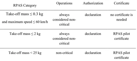
One of the main requirements concerns the need for the pilot to have a “RPAS Pilot Certificate” or a “RPAS Pilot License”: the certificate is required to use RPAS with operating take-off mass less than 25 kg in VLOS operations, while the license in needed to use RPAS in BVLOS operations or RPAS with operating take-off mass equal to or more than 25 kg; the only case in which no certificate or license is required is the use of RPAS with operating take-off mass less than or equal to 0.3 kg, with rotating parts safeguarded against impacts and having maximum speed less than or equal to 60 km/h. These requirements are synthesized in Table 1-3.
Table -3 ENAC requirements for the use of RPAS
RPAS Category Operations Authorization Certificate
Take-off mass ≤ 0.3 kg
and maximum speed ≤ 60 km/h
always considered
non-critical
declaration no certificate is needed
Take-off mass ≤ 2 kg always
considered non-critical
declaration RPAS pilot
certificate
Take-off mass < 25 kg non-critical declaration RPAS pilot
certificate
Furthermore, the operations are divided into:
- non-critical operations, that are VLOS operation which do not overfly, even in case of failures, congested areas (i.e. residential, industrial, commercial, sporting areas and where gathering of people are possible), crowd of people, urban areas or critical infrastructures;
- critical operations (all operations that do not fall into the "non-critical" category).
However, the regulatory debate is still lively and the rules, defined since 2013, have been modified and reviewed almost every year. What has been synthesized in the present paragraph, as written before, is referring to the epoch when the present thesis has been written, i.e. 2018. Anyway, for Italian regulation, it is possible to refer to the official regulation published by ENAC on its official spaces (https://www.enac.gov.it/). The first edition of the “REGOLAMENTO dei mezzi a pilotaggio remoto” (REGULATION of remote-controlled vehicles) has been published in December 2013 and replaced in July 2015 by a second edition, which has been amended 4 times up to the last version published in May 2018 (ENAC, 2018). All this activity in the regulatory field confirms the strong interest on the survey by drone and highlights its fast development, which is still in progress.
2. THE SURVEYS FROM UAV
In this chapter, the main applications of UAV in the field of survey will be described, in order to identify their strong points and critical issues. This analysis allows a better reading and understanding of the innovations proposed in chapter 4 and 5.
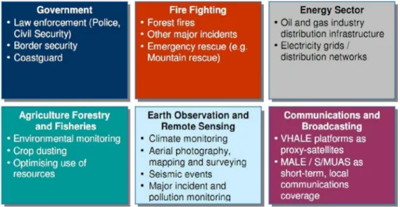
The use of UAS (including the military ones) is certainly connected to their ability to perform the so-called "dull, dirty and/or dangerous" tasks: UAS substitute manned vehicles in all the situations where a pilot and a crew may be significantly at risk of losing their lives or “dying of boredom” (Eisenbeiss, 2004). Moreover, thanks to the decreasing cost of UAV and GNSS/INS systems, as well as the range of available sensors, UAS can be employed in all the situations where a traditional platform (i.e. airplane) would be too expensive to justify its use. The high flexibility and the total low cost per acquired information compared to classical systems – terrestrial or aerial – offer really a high variety of different applications. A widespread use of UAS is aimed to the acquisition of videos and photos for purely commercial and documentation purposes (advertisements, movies, landscapes, real estate and so on). The other applications can be summarized as "observation, maintenance, surveillance, monitoring, Remote Sensing and security tasks” (Eisenbeiss, 2004). In 2007 the European Commission carried out a comprehensive study to monitor the uses of UAS in Europe: the provided list of potential applications for civil and commercial purposes is illustrated in Figure 2-1 (European Commission, 2007). An overview of the survey tasks currently carried out by drones will be proposed below, according to the classifications stressed by this research. The applications privileging the metric aspect to the qualitative one will be preferred.
2.1 Different Fields of Applications
The following picture (Figure 2-1) shows the classification made by the European Commission in 2007.
This research confirms the importance of the survey by drone in several situations and different public and private fields. However, this work prefers a classification based on the task given to the drone regardless of the application field, in order to be able to ponder the importance of the metric quality of results in every category.
2.1.1 Intelligence, Surveillance, Search-and-rescue
The capacity of UAV to travel repeatedly along a defined route at regular intervals in autonomous flight mode and to give updated images of the same scenario at every passage makes them an example of perfect surveillance tools. In fact, drones are commonly used in the control of borders and as support to the coast guard. In the role of surveillance, positioning accuracy is normally not the main issue. In fact, the required metric precisions in the localization of the surveyed object are in the order of magnitude of one meter or more. Therefore, more attention is paid to camera optic characteristics and the high quality of the images.
UAS can be useful also in the prevention and early detection of forest fires, thanks to their "above-the-head" privileged point of view. Indeed, UAS permit to supply real-time videos and information about fire's location, as well as wind speed, temperature, humidity and other parameters depending on the on-board sensors (Merino et al., 2010; Roberts, 2014). In this case the positioning of the observed scene requires a better metric quality, but the dynamic of the scene and the size of calamitous phenomena require metric precisions too.
The flexibility, safety, ease of operation and relatively low cost of ownership and operation facilitate UAS implementation also in disaster situations, such as floods, earthquakes, hurricanes, fires, volcanoes eruptions and so on (Pratt et al., 2006). Unfortunately, there have been several application cases of this kind in the last years and also in the national area like during Central Italy earthquake (August – October 2016). An example of a survey damaged or collapsed buildings in Norcia and Amatrice is described by Gagliolo et al. (2017, 2018).
An overview of UAS usage for disaster monitoring and management can be found in Adams and Friedland (2011). The drones have been used for the first time in calamitous events on an experimental basis in 2005, for the catastrophe of the hurricane Katrina. In 2011, after a devastating earthquake and subsequent tsunami, the Japanese Fukushima Daiichi nuclear facility was significantly damaged and began to emit radiation. This hazard complicated repair and traditional reconnaissance efforts as humans were advised to avoid the area. Thus, remotely operated UAS were deployed: for instance, a T-Hawk Micro Aerial Vehicle with special radiation sensors completed five reconnaissance missions and acquired hours of video and valuable imagery data of the nuclear reactor (Reavis and Hem, 2011). In the nuclear site of Chernobyl, 30 years after the tragedy, the danger for human lives is still high and the present reconnaissance in the Chernobyl Exclusion Zone (ChEZ) are performed by drones. The most recent studies reveal an accurate and reliable UAV-based detection of unknown radioactive biomass deposits in the ChEZ (Briechle et al).
2.1.2 Inspection
Another field of application for drones, which is now developing, is that of inspections. With inspection it is usually meant the visual control of the conservation state of an artifact, like bridges and dams or the check of the functionality of infrastructures, like high or medium voltage overhead power lines. In these cases, the use of drones makes logistics much easier, as it is possible to go near the artifact without the need of mobile lift trucks or harnesses and it makes the work of the inspector safer. Further examples of inspectable infrastructures are roads, railways, oil and gas pipes, photovoltaic installations, historical buildings and monuments.
2.1.3 Cultural Heritage and Archeological Surveys
Cultural heritage 3D models could help in securing, planning and performing the restoration of damaged buildings. Considering this last task, UAS photogrammetry can guarantee the metrical precision of the results, facilitating at the same time the access in areas where otherwise it would be impossible to enter. Furthermore, the instrumentation used by this technique is cheap and the survey operations are performed quickly. Hence, its use is very common and there is a plenty of applications spacing in different fields. The UAS photogrammetric capabilities could be very helpful in emergency situations (e.g. earthquakes), when a high level of precision and accuracy is required to ensure building conservation, as well as to preserve their cultural value.
The use of UAS for post-emergencies events and their integration with different surveying methods has been documented by a number of authors (see for instance Wang, 2014; Achille et al., 2015; Meyer et al., 2015; Ballarin et al., 2013; Gagliolo et al., 2017, 2018).
UAV have become very common also in the survey of archeological sites: the maneuverability of UAV, the fast and easy operation and the possible frequent repetitions of flights have played a key role in the choice of this tool again. In the case of archeological excavations, in fact, it is very important to monitor day by day both the new areas and the results, in order to schedule the following activity. In this context a UAS represents a cheap and efficient solution to create high resolution 3D models and orthophotos, keeping low costs and guaranteeing a good quality.
2.1.4 Traditional Surveying and Cadastral Applications
The use of UAV in surveys is not limited any more to new and particular operating fields, but it is substituting consolidated aerial survey techniques in several situations.
Thanks to the use of gimbals, it is possible to vary the inclination of the optic sensor, allowing to control in a better way the acquisition geometry and having configurations similar to those of close-range photogrammetry. Nocerino, Menna, et al. (2013) show how it is possible to improve the final accuracy by adding oblique images to the nadir ones. In UAS acquisitions it is frequent to have strong variation in the number of overlap images, because of the poor stability of the platform itself and, for this reason, it is necessary to increase the longitudinal and transversal overlap. The along-track overlap is usually about 70 − 90%, while the one along the across-track direction is about 60 − 90% (Skarlatos et al., 2015). The limit of UAV, in comparison to an aerial survey, is the short duration of batteries (less than an hour flight, depending on hardware characteristics, but it may be only 20 minutes) and the need to operate in the area
of visibility of the pilot on the ground, that are the reason why UAV are suitable for surveys of areas not wider than 100 hectares with cartographic or cadastral purposes.
2.1.5 Precision Farming, Forestry and Environmental Applications
New sensors mounted on UAV and optimal procedures for survey, data acquisition and analysis are continuously developed and tested for applications in precision farming. Procedures to integrate multispectral aerial data about soil and crop and ground-based proximal geophysical data are a recent research topic aimed to delineate homogeneous zones for the management of agricultural inputs (i.e., water, nutrients). Thanks to these tools it is possible to realize multispectral and multitemporal orthomosaics and to map vegetation and soil indices. The versatility of UAV allows to perform flights in two moments during the crop season, before sowing on bare soil and just before flowering. During the flights two cameras, for color (RGB) and false color (NIR-RG, Near Infrared-Red Green) images, can be used simultaneously. In addition to this, there are low cost thermal cameras, that can be mounted on lightweight UAV. UAVs have already given evidence of being an appropriate platform for mapping forests and agricultural crops, where aerial or satellite images have poor spatial or temporal resolution (Laliberte et al., 2011; Gini et al., 2014, Dunford et al., 2009, Berni et al., 2009, Nebiker et al., 2008, Hunt et al., 2005). On the other hand, the so-called "precision agriculture" requires information on the inherent spatial variability of soil and crop properties and uses this information to prescribe appropriate management strategy on a site-specific basis (Agüera et al., 2011). UAVs are always used in precision agriculture, in addition to ground observations. In recent years, extensive and accurate studies were done to enhance and speed up the spatial co-registration and the processing of images, in order to generate different kinds of thematic maps for agricultural crop monitoring. Nevertheless, the production of soil or vegetation maps from UAV imagery still presents challenges. Although the spatial resolution is very high, the spectral and radiometric resolutions obtained by the low-cost compact cameras are relatively low. Moreover, poor radiometric and geometric calibrations are often obtained when using common digital cameras. On the other hand, lightweight multispectral and hyperspectral sensors of high quality, which can be mounted on mini-UAV, are available only since few years and are not so widespread due to their high costs. Therefore, it can be said that several efforts have been done to optimize the procedures for acquisition and processing of images taken from UAV, mounting low cost cameras with low spectral resolution.
2.2 Survey Sensors
The overview of the discussed applications is not surely thorough, but it is relevant enough to show how the drone acts as a vector able to carry a specific sensor according to an a priori planned specific flight path in the survey functions. The difference among applications is given by the sensor and the geometry of data acquisition.
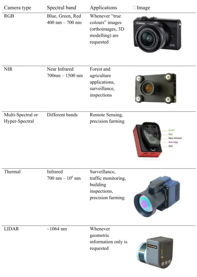
In the last years, a huge growth of low-cost and low-weight sensors, suitable to be mounted on very light and light RPAS has been registered. Different solutions are available on the market, both active and passive sensors, that can be employed in agroforestry field with many purposes. Among passive sensors, several types of cameras can be distinguished: RGB cameras, sensitive to the visible part of the electromagnetic spectrum (about in the range between 400 and 700 nm), Near Infrared (NIR) or Color Infrared (CIR)
cameras, which can detect also near infrared wavelengths (from 700 to 1200 nm), thermal cameras, sensitive to the thermal infrared wavelengths (about 8000 – 14000 nm) and, finally, multispectral and hyperspectral cameras, that allow to acquire a varying number of bands, equal to the number of optics or registration channels (in case that electromagnetic radiation is divided after its entrance in the sensor lens). A particular type of sensor is LIDAR. It is an active sensor able to generate georeferenced point clouds, which include also information about surface reflectance of the laser beam sent from the LIDAR itself. Whereas for passive sensors the data processing involves analysis and combination of different spectral bands, for LIDAR the geometric information is especially examined: in agroforestry applications LIDAR are employed for evaluating vegetation growth, for estimating biomass or for acquiring terrain morphology for hydraulic studies (Wallace et al., 2014; Malinowski et al., 2016; Bareth et al., 2016).
All sensors have weight varying between few tens grams (i.e. Action Cam) and some kilograms (i.e. LIDAR), hence suitable to be mounted on the most of RPAS. Even their costs are very variable: optical cameras prices start from a few tens euro for the RGB Action Cams up to around 10,000 euro for multispectral cameras (Nebiker et al., 2016), while LIDAR are expensive (more than ten thousand euro) and for this reason not diffusely used.
Table 2-1 Sensors and field of application
Camera type
Spectral band
Applications
Image
RGB Blue, Green, Red 400 nm – 700 nm Whenever “true colours” images (orthoimages, 3D modelling) are requested
NIR Near Infrared 700nm – 1500 nm Forest and agriculture applications, surveillance, inspections Multi-Spectral or Hyper-Spectral
Different bands Remote Sensing, precision farming Thermal Infrared 700 nm – 106 nm Surveillance, traffic monitoring, building inspections, precision farming LIDAR ~1064 nm Whenever geometric information only is requested
3. UAV PHOTOGRAMMETRY
According to Kraus’ definition, “Photogrammetry is the art and science of determining the position and shape of objects from photographs”, in particular, it is the process of extracting metric information from an object through measurements made on photographs (Kraus, 1993).
In this chapter the basic principles of photogrammetry and the use of Unmanned Aerial Vehicles (UAV) in this field will be discussed. After defining the concept of photogrammetry, its theoretical principles will be presented: the central projection model, on which photography is based, and the different phases of the photogrammetric campaign. Finally, it will be briefly presented how, thanks to the development of UAVs, the relationship between photogrammetry and Computer Vision has changed in recent years.
This introduction to photogrammetry is not intended to be exhaustive. Its purpose is just to introduce the reader to concepts that will be treated in more detail later.
3.1 Characteristics of UAV Photogrammetry
In the last years the definition “UAV Photogrammetry” has been introduced in the scientific literature. The first use of the term is thought to be in the Eisenbeiβ (2009) PhD thesis, where it was used to identify a photogrammetric measurement platform that could be remotely controlled or could fly completely autonomously. The platform could be equipped with a photogrammetric measuring system that included tools, such as small or medium size cameras, video cameras or action cams, or other sensors. In this regard, the photogrammetry from UAV opens new possible applications, especially in the short-range field, since it is a good compromise between aerial and terrestrial photogrammetry.
The use of drones in photogrammetry has several advantages over aerial photogrammetry platforms, such as airplanes, helicopters and satellites. The advantages can be summarized as follows:
- lower initial and maintenance costs;
- it is not necessary to have a qualified pilot on board; - the drone is easily maneuverable;
- the drone can fly autonomously following a pre-established flight plan;
- the survey is fast and, in general, repeatable several times in a short period of time; - generally, there is the possibility to see in real time what the camera is acquiring;
- it is possible to carry out surveys in areas not accessible to other aircrafts and there are no limitations given by the presence of high-altitude clouds;
- UAVs can be used in high risk situations and inaccessible areas (e.g. natural disaster sites, accident scenes, mountainous areas);
- if using multirotor UAVs, it is possible to take-off and land vertically in narrow spaces and to acquire images on a hovering point;
However, there are also some limitations in the use of drones:
- the need to reduce the weight of the aircraft as much as possible to increase flight endurance; this, together with the limits on the dimensions, leads to equip the drone with compact instrumentation, generally of lower quality compared to that used with larger aircrafts;
- the need for systematic calibration of the camera on board, because it's not usually a metric camera; - the difficulty of flying in the event of wind on the ground or at altitude;
- there is a strict ENAC regulation for their use.
3.2 Theoretical bases of photogrammetry
Photogrammetry is a survey technique that allows to recreate the shape, dimensions and position of a three-dimensional object starting from two-dimensional images of it. The basic principle consists in the partial overlap of consecutive stereometric frames taken from different points. These frames are taken while the camera is moving, so that they show the object from different positions. To determine the three-dimensional coordinates of the object, it is necessary to identify the same point on at least two images and draw the projection rays: the three-dimensional position of the point is identified by the intersection of the rays.
A photogrammetric campaign consists of the following phases (Cannarozzo et al., 2012):
- acquisition phase: the object is photographed from several positions, ensuring that each frame partially overlaps with those that follow it and precede it;
- orientation phase: according to mathematical principles, the position and orientation of images at the time of acquisition are reconstructed;
- restitution phase: a 3D object model or a point cloud is generated in three-dimensional space starting from the two-dimensional images.
The photogrammetric technique is typically used in the field of architecture, construction and civil engineering for surveys of buildings or entire areas of the territory. It can be performed from the ground or from an aircraft (e.g. drone, airplane, helicopter or satellite).
3.2.1 The basic principle of photogrammetry
The central projection model is the model behind the photographic technique: each point on the image plane is the central projection of the corresponding point on the object in the three-dimensional space. The model is shown in Figure 3-1 in which:
- P is a generic point in the space;
- P’ is the image of P and belongs to the image plane;
- O is the projection center, it coincides with the ideal point where every ray light pass to impress the sensor creating the image;
- c is the focal distance or, more exactly, the principal distance, that is the distance between O and the camera image plane; it isa characteristic of the objective.
Figure 3-1 Central projection model
To describe appropriately a three-dimensional object in space, at least two frames from two different projection centers are required. One single frame is not sufficient because, as shown in Figure 3-2, a generic point P’ belonging to the image plane having as center of projection O1 can be the projection of infinite points P1, P2, P3... along the projection ray. Therefore, it is not possible to uniquely determine the point P belonging to the real object. Instead, if two different frames are used with different centers of projection O1 and O2, it is possible to univocally determine the position of point P at the intersection of the projection lines coming from P’ and P’’ respectively on the frame 1 and 2, image points of the object point P. This principle is at the base of photogrammetry and is shown in Figure 3-2.
Figure 3-2 Basic principle of stereo-photogrammetry
This projection connects the points of the object with the projection centre and, intersecting the projection plane, generate the image points that are the point projections. The consolidated photogrammetric approach, reasumed for instance by Kraus (1993) and other authors, explain that, when we acquire a frame, the object point P, the projection centre O and the image point P’ lie on the same straight line. The mathematical representation that indicates the collinearity conditions, representing the alignment between the points in the image and in the object system, in the simplest case when the image and the object frames are aligned can be expressed in the following way:
!"!# $ = &'"& #' (#'"() +"+# $ = ,)",#' (#'"() (3.01)
where ξ and η represent the image coordinates, ξ0 and η0 represent the principal point coordinates, c is the principal distance, X’, Y’, Z’ the coordinates of the object point P and X’0, Y’0, Z’0 the coordinates of the projection centre that may be processed in the system X, Y, Z by the spatial rotation matrix R:
-𝑋 − -𝑋0 𝑌 − 𝑌0 𝑍 − 𝑍03 = 4 566 567 568 576 577 578 586 587 588 9 ∙ ; 𝑋′ − 𝑋′0 𝑌′ − 𝑌′0 𝑍′ − 𝑍′0 = (3.02)
So, if we multiply the matrix above for the matrix RT = R-1 and replace the latter in the equations, making explicit the image coordinates, we will get the relationship between the image coordinates and the ground coordinates, called the collinearity equations:
𝜉 = 𝜉0− 𝑐 ∙566(&"&#)B576(,",568(&"&#)B578(,",#)"586(("(##)"588(("(#)) (3.03)
𝜂 = 𝜂0− 𝑐 ∙567(&"&#)B577(,",#)"587(("(#)
568(&"&#)B578(,",#)"588(("(#) (3.04)
The collinearity condition is expressed by non-linear equations and the estimation of the coordinate X, Y, Z of point P, at the intersection of the straight lines of each frames, is computed with a least squares estimation. For this reason, the expressions can be rewritten in terms of differential relations, and approximate initial parameters must be recovered to solve the system.
3.2.2 Image Acquisition Phase
In all the photogrammetric approaches (aerial, terrestrial, close-range or UAV) planning data acquisition is a fundamental step.
Especially in the case of UAVs, drawing a flight plan allows a reduction of the number of images and of flight time. This is essential to optimize battery consumption and to reduce the processing time of the acquired images. A flight plan also allows us to define the expected resolution of the final product and to define other flight parameters. Flight planning should also take into account the weather and light conditions (which can interfere with the flight and the image quality), wind speed (that is significant in the case of lightweight systems) and system vibrations (that have to be avoided or compensated during the flight).
In relation to the specific case study, a flight plan needs to be designed taking into account operative variables, as well as the area and the expected result.
First, the UAS type best suited according to the size of the area: fixed wings are preferable for big areas and multi-rotors for smaller ones. Then it is important to a priori define the objectives to be achieved in
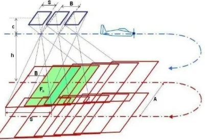
terms of the resolution and accuracy in terms of GSD (Ground Sample Distance) and the block orientation precision. These parameters have to be considered in the flight planning (Figure 3-3).
Figure 3-3 Flight plan schema for flat ground
Starting from well-known formulas, the main parameters to be considered for an aerial flight (in the
normal case: camera axes are perpendicular to the base B and parallel to each other) are:
Image scale factor:
mb = h/c (3.05)
where c is the principal distance and h is the relative flight height; Image size on the ground:
Sx = sx · mb; Sy = sy · mb ; GSD = dpixel · mb (3.06)
where sx and sy are the sensor sizes and dpixel is the pixel size (in the same units of the
principal distance c, generally in millimeters); base length (distance between consecutive
images) for a given forward overlap percentage l:
B = Sx ·(1 – l /100) (3.07)
distance between strips for a sidelap percentage q:
A = Sy · (1 – q /100) (3.08)