AND INFORMATION
MASTER OF SCIENCE – MECHANICAL ENGINEERING
3D SHAKER
vibrating machine used for tests designed to damp and reduce
vibrations harmful to the human body
Supervisor: Hermes Giberti
Edoardo Negri
Non ho alcun talento particolare, sono solo appassionatamente curioso.
INDEX
Summary
...
5
Chapter 1: Introduction
...
7
1.1: State of art shakers ...9
1.2: Tests carried out on people with various types of shakers ...11
1.2.1: Tests on vehicle seats ...11
1.2.2: The monitoring of the comfort of vibrations ...12
1.2.3: Transmission of whole body vibration in children while standing 13... 1.3: Objectives of the project ...14
1.4: Specific dynamics and dimensional ...14
Chapter 2: Kinematic project
...
15
2.1: Introduction of kinematic parallel robots ...16
2.2: History of Kinematic parallel robot (PKM) ...17
2.3: Nomenclature for PKM ...21
2.4: Choice of the linear delta configuration ...22
2.5: Kinematic analysis ...23
2.5.1: Inverse Position Kinematics (IPK) Solution ...24
2.5.2: Analysis of speeds, Jacobian matrix ...28
2.6: Kinematic optimization and performance index ...30
2.6.1: Numerical optimization ...31
2.6.2: Working area ...32
2.6.3: Work area analyzed ...33
2.6.4: Optimization of the values base radius and link length ...34
Chapter 3: 3D Shaker Project
...
39
3.1: Fixed part ...39
3.2: Mobile part ...41
3.4: Complete 3D shaker and overall dimensions ...51
Chapter 4: Sizing
...
53
4.1: Multi body model ...53
4.1.2: Radom signal ...56
4.2: Adams results ...57
4.3: Geared motor choice ...60
4.3.1: α - β method ...60
4.4: Geared motor chosen ...65
4.4.1: Brushless motor Omron l3k030c-400v ...65
4.4.2: Linear guide Rollon TV-110-32-32 ...66
4.5: Real motor torque ...67
4.6: List of brushless motors analyzed ...68
4.7: List of Rollon linear guides ...71
Conclusion
...
73
Future developments
...
74
Bibliography
...
76
Image list:
...
78
Appendix
...
81
[A.1] Data sheet ...81
[A.2] Drawings ...84
[A.3] Matlab script ...93
Jacobian matrix ...93
Linear inverse kinematics ...93
Linear inverse Jacobean ...94
Manipulation along the work space ...94
Manipulation as function of s and l ...97
It has been known for a long time [ 1 ] [ 2 ] that the mechanical vibrations transmitted into the body can bring about health risks and in particular in the safety of workers, causing backache and lumbar traumas (structure of support of the head).
The human body can be seen as a dynamic system that responds in a different way ac- cording to the frequency it is exposed to. From minor frequencies to frequencies of a per- son estimated around 20 Hz, the human body responds in a uniform way, just like a ho-mogeneous and unique mass thanks to the ability of the muscles to tighten up and con- tract the stress. For bigger frequencies (more than 20 Hz - the human body reacts in a non homogenous way in its components. The voluntary muscles are not able to contrast completely the oscillator movements of its parts and its vibrating engine that cushions inside the body and is interested only in a relatively limited area around the the point of application. Studies of biodynamic have highlighted between the possible mechanism of injuries to the muscle-bone of the lumbar apparatus, the mechanical excess load caused by the phenomenal of a resonance of the spinal column in intervals of frequencies bet- ween 3 and 15 Hz (seats of lorries/vans, etc.) Consequently there is structural damage to the vertebral column, discs and articulation.
The aim of this project is finalized in the creation of a system able to generate vibrations through a platform, where they will go and stimulate the various types of conditions that a person can encounter.
As indicated above they are of particular interest the vibrations in the range of 0-20 Hz given that they are those that impose the most damage to the human body.
To reduce risks and to increase the well being of the person it is necessary solutions sui- table to the attenuations of the vibrations for example shock absorbing shoes. to be able to achieve this type of solution it is necessary to have available a source of vibrations to be able to test and certify them.
This work is concentrated on the design of a system that is able to generate different ty- pes of vibration that can vary from the classic sinusoidal to the rectangular, triangular and
Chapter 1: Introduction
The vibrations, acting on the human body, have been studied for a long time because they can both bring benefits and problems.
The whole-body vibration (WBV) [ 3 ] which was initially termed as “rhythmic neuromuscu-lar stimulation” in the 1960s was brought to interest when a study demonstrated the sti-mulus could affect trunk flexion (Biermann 1960). Since then, several beneficial claims as-sociated with WBV have warranted continuous research on the use of vibration platforms in multiple domains. In the strength and conditioning domain, whole-body vibration trai-ning (WBVT) is promoted by research indicating improvements in muscular strength, po-wer and flexibility.
But it is also true that studies [ 4 ] about mechanical vibrations transmitted into the body can bring about health risks and in particular in the safety of workers, causing backache and lumbar traumas (structure of support of the head).
There are a number of people who need to be concerned with vibration damping, espe-cially for their workers who are using heavy machinery and those who spend long hours on their feet near machines or behind the wheel of a vehicle. An example is the study [ 4 ] done on tractor drivers exposed to whole-body vibration to investigate the occurrence of low-back pain (LBP). It has been discovered that the occurrence of this type of problem is related both to the amplitude and to the frequency.
Studies are also conduced on non-work footwear [ 5 ], for example running shoes, to stu-dy the capability of absorbing shocks to improve wellness and comfort. One of the key features of a running shoe is the ability to reduce impact shock during the first phase of the heel strike, even if the role of cushioning has nowadays been reduced to possible ef-fects on comfort and fatigue instead of injury prevention.
Mechanical vibrations are damaging for the human being because they go to different parts of the body, ankles, knees and even the neck, the resonance is increasing, someti-mes even double the value of acceleration that the body receives. Furthermore a regula-tion exists. the UNI -EN ISO 2631-1:2014 that establishes the daily measures of exposure of which workers can be subject to, relating to the levels of action and the limited levels
vibrations of both evaluated through the means of the calculation of acceleration equiva-lent to the referred frequency of 8 hours of work.
To be able to study solutions more efficient to absorb and soften the vibrations it is ne-cessary an instrument that produces them, a shaker. In the present case it has been crea-ted a shaker 3D able to generate vibrations in the 3 principal directions through a platform made with 3 motor powered shafts.
1.1: State of art shakers
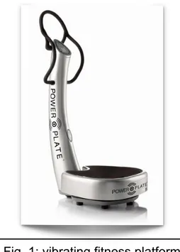
There are already various types of shakers in commerce and it is possible to find them anywhere, in a gym, under the form of a vibrating springboard.
Obviously there are models more sophisticated, that range from models of electrodyna-mic, mecchanical and air compressed. A comparison of these can be seen in [fig.4] where the advantages and disadvantages are underlined. A mechanical shaker, an example of an unbalanced mass or camshift, it has the quality of a simple system, reliable and easy
to produce. A disadvantage, by its nature is the size of the vibrations generated are gene-rally fixed, so on a low frequency they can be used only for slow movements. Another di-sadvantage is the impossibility of generating vibrations at random that would be possible to obtain with a pneumatic or electromagnetic system. On the contrary the electromagnet models are very versatile because they are able to reach without a doubt high frequencies with acceptable movements without being noisy.
Their main inconvenience is given to the high cost of the production, even in the configu-ration 3D, which is able to generate movements in main directions, must be equipped with 3 electromagnets one for every direction.
1.2: Tests carried out on people with various types of shakers
1.2.1: Tests on vehicle seats
To be able to evaluate the levels of exposure of which a person is subjected to it is ne-cessary to carry out calculations in the workplace or conduct tests in the laboratory. As a rule the tests are carried out in the laboratory when the company has the necessities to develop a new product, that can be a shoe, a floor covering, a chair or anything else that can be inserted between the source of the vibrations and the person.
The PHD thesis [ 6 ] has considered the study of a seat for vehicles. The test includes a platform, built by a Japanese company Shinken Co. LTD,
having 2 gdl, longitudinal and vertical, able to move thanks to two actuators with electro-dynamics control separated on the shafts and with a pneumatic system of support for the centering of the table.
The performance obtained with this system are: • Frequency range: 0.5 ÷ 100 H z
• Maximum acceleration: 8.3 g a vuoto e 3.1 g con carico di 200 kg • Maximum speed: 1.2 m/s
• Maximum displacement: ±25.5 mm (sia verticale sia longitudinale).
1.2.2: The monitoring of the comfort of vibrations
A simpler example of shaker we can find in the work of a thesis [ 7 ]. The aim of this study is to individuate the answer to the frequency of the spinal column regarding the anthro-pometric features. Being interested in the FRF, between the vertical acceleration of the platform and the measured acceleration of the top of the head, it was also necessary for a shaker able to generate vibrations purely vertical. The instrument used was a fitness board readjusted to be able to take advantage of the engine and its piston rod crank sy-stem to rotate a surface of +2,5. The subject of the experiment is made seated in an erect position on a base able to oscillate around a tree. The end of this base is to avoid the obliques movements, caused by rotation, as much as possible.
1.2.3: Transmission of whole body vibration in children while standing
The vibrations have been used for therapeutical interventions on children with the syn-drome of "imperfect osteogenisis" resulting in an increase of bone density. This positive result though hasn't shown if this treatment could damage children in any way.
A study [ 8 ] has analyzed how the vibrations become absorbed by a child in comparison to an adult. This therapy is used with optimal results on adults without any side effects but before this test there weren't any tests done to determine if a body of a child re-sponds to the vibrations in a similar way of that of an adult.
The test was performed using a vibrating rationing automated platform where children had to remain on their feet whilst the platform was in function.
The movement was chosen only harmonious with frequency of 28,33,42 Hz and a move-ment respectively of 0.97, 1.17 and 1.53 mm. The data on the individual were obtained through the luminous markers filmed by the videocamera. The results have demonstrated that there aren't significant differences in the behavior less of hips and ankles but only of a frequency of 33 Hz.
1.3: Objectives of the project
The goal of the project is the creation of a 3D shaker able to generate vibrations useful for the study of the effectiveness of various types of footwear in absorbing and attenuating vibrations harmful for the body. It will also be used as a test bench for a project that invol-ves integrating a measurement system into shoes to measure the vibrations transmitted to athletes and workers.
To fulfill its purpose the shaker will have to operate a relatively large space by preferring the vertical direction. This will distinguish it from the others as often there are models that operate in relatively small volumes.
Another fundamental characteristic for a vibration is the frequency. This must be limited in the range 0 - 30 Hz, because here are the most damaging for the body.
Besides the amplitude and frequency, the type of signal is also important. Generally a vi-bration that comes from the ground is composed of many different contributions and can be considered random. Therefore the shaker will have to provide a random vibration. Since the tests are aimed at the comfort and safety of people, it is expected that the sha-ker will operate by supporting an adult with a weight not exceeding 100 kg.
1.4: Specific dynamics and dimensional
Our goal is to create a robot by means of generating a signal, or vibrations, in the fre-quency range between 0 and 30 Hz so to carry out tests on people and evaluate the effi-ciency of certain materials, footwear and improvements, in the absorption and softening of these vibrations.
Regarding the cinematic of the machine it is requested to generate 3 dimensional trajec-tories of any genre (linear, sinusoidal, random etc.) +-30 mm in x and +-20 mm in x and y, building a parallelepiped form of work space.
The limits, in terms of performance, are given by the accelerations, to be specific the plat-form guarantees an acceleration up to 5 m/s^2 in vertical direction (z) and up to 2 m/s^2 in the other two directions (x and y).
Chapter 2: Kinematic project
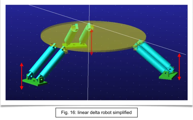
The shaker must be built by a flat surface that moves in space, giving importance to ver-tical movements, of a reduced weight to allow it to reach higher frequencies. Against this a delta structure has been chosen, type of parallel Kinematic robot.
There are different existing types on the basis of how they are actuated the shafts and their disposition with their pros and cons. This structure permits the maintaining of the engines and the heavy masses still on the floor to move only the lighter components to
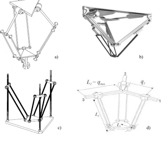
Fig. 8: various types of delta robots. a) Clavel’s delta b) and d) linear delta with inclined axes c) linear delta with parallel axes
a) b)
2.1: Introduction of kinematic parallel robots
A parallel kinematic robot is a system in which if they have some kinematic chain that connect the ground with the platform, based on a type of application that it desires to ob-tain a number, the type and the position of this chain can vary significantly. The nomen-clatura commonly used for these robots is expected to call base the structure or the ground to which you still have the mechanism, link the rigid arms that go from one joint to another and end effector (mobile platform in the figure) the part of which you study the movement.
A parallel robot [ 9 ] is designed in such a way as to allow each arm to be short, simple but also rigid to counter unexpected movements of the platform. The errors in the move-ment of an arm are compensated and dampened by the other arms instead of being ad-ded, but each arm can move only within its degree of freedom. It is this compensation mechanism that constitutes the necessary rigidity of the system with respect to its com-ponents.
The best known parallel robot is made up of six pistons (or actuators) that support a mo-bile platform, fundamental for many devices, such as flight simulators. This system is cal-led the "Gough-Stewart platform", named after the two engineers who created it and used it for the first time.
2.2: History of Kinematic parallel robot (PKM)
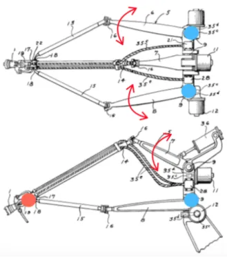
The first studies of Kinematic chains, of which there is a trace, go back to Cauchy in 1813 before the first studies. It was more than 100 years before that the concept of kinematic robots was developed. The first patent, the most famous, that talks about an industrial robot of this type thanks to Willard L.V. Pollard [ 10 ]. He invented a machine at 5 degrees of freedom, engine powered with punch card, actions of the automatic paintwork of the body of vehicles from the photo the system is composed of 6 arms, three of these are connected to the floor, through universal joints (●). These are motorized, while the remai-ning three are connected to each of the previous arms mentioned. Finally they connect to a unique point called End Effector (●).
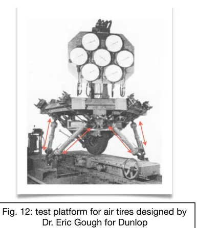
Always in the same years, but from the other side of the ocean, Dr Eric Gough created for Dunlop, who he was working for as an engineer, which would become the most famous iconic kinematic parallel robot. This was created and built to be a universal machine for tests able to meet to the necessities of time, to test airplane pneumatics under agent loads in any direction. The robot created is an hexapod octahedral having 6 degree of
pistons. The structure distributes the loads on 6 legs and this makes suitable to support the high stress that those of an airplane when landing.
In 1965 Mr D Steward of the Institutions of Mechanical Engineers patented a similar sy-stem of that of Dr Eric Gough finalized to the realization of aeronautic simulators. Nowa-days most of the simulators are still produced with this architecture, that is defined plat-form of Gough-Steward.
Fig. 12: test platform for air tires designed by Dr. Eric Gough for Dunlop
More recently, in the 1980's, Reymond Clavel together with his team invented the delta robot. The aim of that was to realize a system able to move quickly small light objects from one place to another. This operation is called Pick and Place and the robots still used today are based on the same kinematic invented by Clavel.
A variant of the delta of Clave is a linear delta, instead of having 3 spherical joints con-nected to the floor, it has three prismatic that allows an extreme limit of the arm to move. This configuration nowadays has had a major purpose of 3D printers.
Their advantage is to be able to reach high acceleration and speed of the End effector as compared to those imposed to the actuators that they are rotational or translation. Their structure furthermore distributes the loads on three or six legs, according to the configu-ration, characteristics that makes it rigid and suitable to support elevated loads.
However this architecture has some inconveniences, primarily coming from their mathe-matics. How it is noted from the brief history described previously, the first robots able to move appeared only at the beginning of the 90's, because there are complex equations that connect the movement of the joints with that of the end effector. Only with an on-going development of informatics and electronics it is possible to realize a computer suf-ficiently powerful and compact able to resolve these equations and check the robot. The robot of Dr Eric Gough is a machine that applies static loads so it doesn't require a com-puter to calculate the position of joints in that they remain prior in a well-defined position.
2.3: Nomenclature for PKM
Link:
the link is that part that connects a joint to the base.End Effector (EE):
with this term the component is pointed out to which the links are connected, that has the possibility to stir in the space of which the movement studies him.Joint:
the joints are the elements of the robot that are effected for allowing the EE to complete one determined trajectory.Pose:
with pose are pointed out a configurations of the robot, defined the variables of the joints it is gotten one determined pose and vice versa.Work space:
to this space make reference the variables of potion of the EE, besides it can also be seen how the volume or area, in which the End Effector can work.Joint space:
to this space they make reference the variables that the position of the joints of the robot describes. Usually the joints have only a degree of liber-ty and this makes the dimensional mono space.Singularity:
this term indicates the condition in which large forces / torques applied to the joints result to be small forces impressed at the EE, vice versa in terms of velocities low velocities of the joints are transformed at high speeds to EE. Generally these areas reside at the margins of the work area, but it can not be excluded that they can also be inside.2.4: Choice of the linear delta configuration
Among the various parallel kinematics solutions available we opted for the linear delta so-lution. This allows wider displacements with the same size compared to its similar, also prefers the vertical movement, which is of particular importance for this application, as we will see later.
The structure is composed of two main subassemblies, a fixed one that constitutes the machine frame and a mobile one composed by links and the platform.
This structure is characterized by three linear guides, rigidly constrained to the ground, each having a prismatic joint. Each of them hosts a slide that translates vertically in the Z direction to which two links are connected by means of spherical joints. Consequently, these ones are connected with two other spherical joints to the platform (end effector) closing the kinematic chain.
In this case, the end effector has the possibility of moving in the x and y directions, but not to rotate with respect to any axis. The movements of the platform are therefore de-termined by the combined movements of the three guides.
2.5: Kinematic analysis
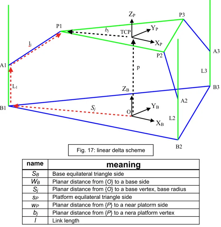
The starting point in the study of a configuration of this type is to find the relationship between the position of the center of the platform or TCP (Tool Center Point) and an origin O, which in this case it has been chosen on the axis of symmetry of the structure.
For this reason, a vector closure has been created consisting of the vectors sj, qj and lj to
name
meaning
S
B Base equilateral triangle sideW
B Planar distance from {O} to a base sideS
j Planar distance from {O} to a base vertex, base radiuss
P Platform equilateral triangle sidew
P Planar distance from {P} to a near platorm sideb
j Planar distance from {P} to a nera platform vertexl
Link length
Writing a vector closing of this kind it is possibile to identifies the fundamental dimensions of the robot, Sj, bj and l, which ultimately determine its performance. bj has been defined a priori, so it will be taken as a constant, since having to host a person standing the plat-form must be sufficiently spacious.
2.5.1: Inverse Position Kinematics (IPK) Solution
Inverse kinematics is the process by which, when the EE position is defined, the positions of the joints are calculated.
As previously written, in order to find the relationship between the position of the end ef-fector and the position of the joints, a kinematic closure has been found which, written in matrix form, has the following expression:
Fig. 18: a) base. B) platform a)
b)
[BB
The terms terms in the specific are:
[ PBi ]: the matrix contains the position of the three points B1, B2 and B3 with respect to
the origin O.
[ PPi ]: the matrix contains the position of the points P1, P2 and P3 with respect to the
ori-gin of the TCP platform.
[ BLi ]: the matrix contains the unknown position of the joints, or points A1, A2 and A3.
[ PPi ]: the vector contains the coordinates of the TCP with respect to the origin O.
[ li ]: The matrix contains the vectors corresponding to the 3 links. PB 1= [−S2B, − WB,0]T PB2 = [S2B, − WB,0]T PB3= [0,Sj,0]T PP 1= [−s2p, − wp,0]T PP2= [s2p, − wp,0]T PP3= [0,bj,0]T B
P
P= [x, y, z]
T BL i= [0,0, − Li]T Bl 1= [x + a, y + b, z + L1]T Bl2 = [x − a, y + b, z + L2]T Bl 3= [x, y + c, z + L3]T a = SB 2 − sp 2 b = Wb− wp c = bj− SjBy squaring both members of the matrix equation [1] we obtain three scalar equations, each referred to one of the three joints, with the following expression:
To simplify the problem, we prefer to group the known terms x, y, z, a, b, c and l into a single constant for each expression as follows:
By doing this it is possible to rewrite the equations [3] in a simpler form:
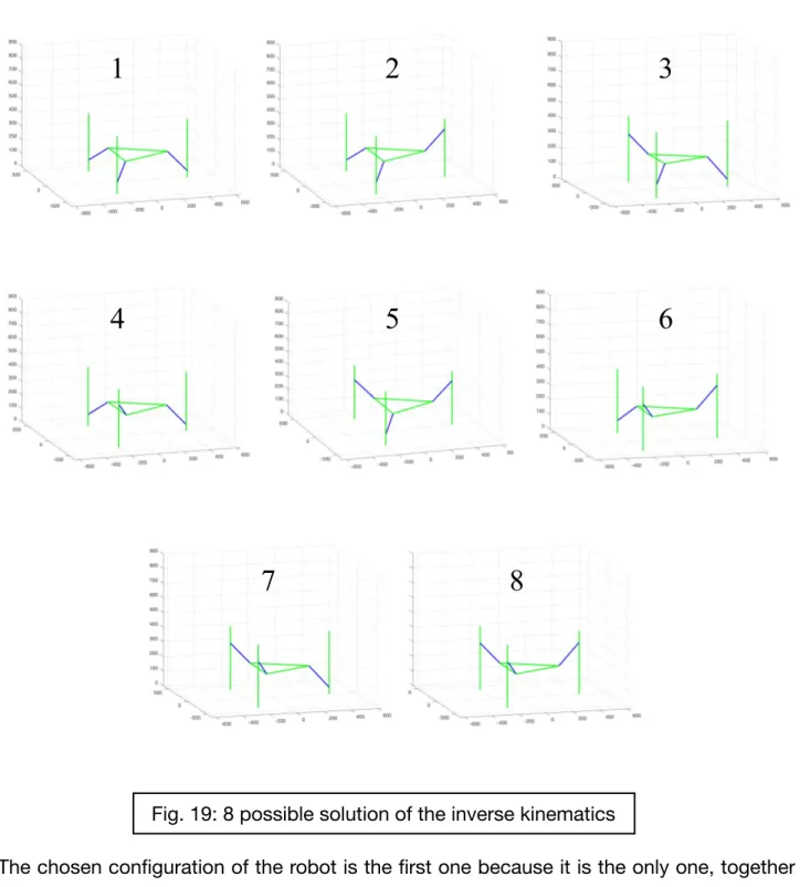
It is noteworthy that, for each equation corresponding to a joint, two solutions are possi-ble, given that there is a square root, equally valid. This leads to the conclusion that since two solutions are possible for each of the three variables, eight exact configurations can be obtained.
[2]
[3]
The chosen configuration of the robot is the first one because it is the only one, together with the eighth, to have an equal configuration on all three links and it allows to hold a standing person, moving he or she away as far as possible from the mobile parts of the machine.
1
2
3
4
5
6
7
8
2.5.2: Analysis of speeds, Jacobian matrix
To determine the two remaining dimensions, base radius Sj and link length l, it is necessa-ry to find a parameter that indicates the performance of the robot according to these. Fir-stly, the relationship between joint velocity and end effector velocity is defined by deriving expression [2] respectively to time:
In matrix form the equations can be rewritten in the following form:
Finally, to determine the vector velocity in the joint space, the matrix B is inverted and multiplied with the matrix A. A
[6]
[7]
In this way we obtain the so-called Jacobian matrix [ J ], which is the one that allows us to get the velocities of the three joints, known the velocities in x and y direction of the end effector. The matrix J is an expression of the transmission ratio that exists between the space of the joints and the work space, in other words, it performs the same function of τ in transmissions to a degree of freedom. The speed of each joint depends on all three components of the end effector's velocity. It is interesting to note that the third column is composed exclusively of 1, this because the platform translates vertically in space just like the joints and therefore in the case where the velocities x’ and y' are zero, the veloci-ties of the joints correspond exactly to the velocity EE.
A second important observation to make is that [ J ] is not constant, in fact it depends on the position of the EE (x and y) and this suggests that the relationship between the veloci-ties of the two spaces varies according to the robot's pose.
2.6: Kinematic optimization and performance index
Before choosing the best value of the geometric parameters, it is necessary to define an instrument able of characterizing the behavior of the machine.
The parameter used to figure out the characteristics of the robot are the ellipses of speed manipulation.
To make clear the concept of ellipsis of manipulability we refer to a Cartesian robot, be-cause of its simplicity, which has the possibility of translating the EE only in the x and y direction. Known the maximum speeds achievable in both axes, it is possible to calculate the resultant according to the formula:
What is obtained from the vector sum is a rectangle, which in the case of equal perfor-mance on both the axes would become a square. Within this area, it is possible to inscri-be an ellipse tangent to the four corners of the rectangle, thus constructing the ellipsis of
[10]
Fig. 20: cartesian robotmanipulability in speed which, in the case of the square mentioned above, would turn out to be a circle.
In this simple case we understand the usefulness of this type of approach, because by calculating the relationship between the axes, it is possible to get an idea of how far you are from the isotropy of operation.
In a more general case, there are robots with more degrees of freedom operating in a th-ree-dimensional work space with speeds that are not always perpendicular to each other. In this case parallelograms are obtained, instead of a simple rectangle, that for simplicity of representation and calculation, are replaced with parallelepipeds and, similarly to the previous situation, an ellipsoid is inscribed inside it.
At this point an index of manipulability could be configured with the volume of the ellip-soid, which is proportional to the determinant of [ J ], but would be too tied to the size of the machine and would not provide a clear indication. What we prefer to use instead is the ratio between the minimum and the maximum singular value of the jacobian that cor-responds to the inverse of conditioning number. The value obtained is between 0 and 1, where 1 indicates that the robot works in an isotropic configuration, while numbers near to 0 indicate that it is close to a singularity.
2.6.1: Numerical optimization
The optimization is aimed at finding the best basic radius and link length parameters whi-le maintaining fixed platform radius, defined as constant because the platform must be large enough to accommodate a standing person.
The optimization method chosen is a numerical type using Matlab, referring to the inverse parameter of conditioning number of J, which will be named for simplicity only K. As
mentioned before the matrix [J] depends on the laying of the robot, so for each point of the working space you have different [J] with different indexes of manipulability. For this particular type of robot, the linear delta, it is more appropriate to consider a work plan ra-ther than an area, because the platform moving up or down does not change its configu-ration and therefore the performance remains unchanged.From an analytical point of view, this behavior is described by the independence of K from z.
2.6.2: Working area
The figure below shows the value of K, using the surface command of Matlab, through a
configuration of random parameters, mapped in an area between -70<x<+70 e -50<y+70:
It is possible to distinguish mainly two zones, one where the index is equal to 0 (dark blue) and a second where the index is greater than 0. In the first region, the null value indicates that the robot is physically unable to reach those coordinates, which consequently will not be part of the working area. The second area has an almost triangular shape and it is cha-racterized by an edge, which is configured with a yellow dotted line. Here the index chan-ges from 0 to a positive value up to the center (x = 0, y = 0), where it reaches its maxi-mum. This is considered the working area of the robot, the one where the EE can operate. In the case in question, it will not work in its entirety, but rather in a portion of it, since a
singularity condition would occur near the edges. In this way the robot would work with difficulty, risking to cause structural damage.
2.6.3: Work area analyzed
What we analyze from now will be only the area between -20<x<+20mm and -20<y<20mm. A 3D representation shows K in the working area, which is the same
en-closed by the red square in [fig. 19].
From this analysis, we can extract two fundamental values, that are the maximum and the minimum value of K in the working area, that will be called K-MAX and K-MIN. In this
case they are respectively 0.92 and 0.55. To obtain better performances, it is necessary to have a configuration with the highest possible values, so in the next paragraph, a numeri-cal method will be shown to identify the optimal base radius pairs and link lengths.
Fig. 22: work area portion of a linear delta robot between -20 <x <20mm and -20 <y <20mm
2.6.4: Optimization of the values base radius and link length
In order to find the optimal value of the base radius and link length parameters, a Matlab script was created to calculate the maximum and minimum value of K for various
combi-nations of the two parameters. It was decided to analyze a range of values that for base
radius range from [250; 500mm] and for link length [150; 250mm], for a total of 25,000
combinations. What we have obtained are two graphs, one for MAX and one for K-MIN, which show their trend according to the two parameters.
The dark blue regions, in both images, roughly included in the value zone base radius [450 ;500] and link length [150 ;200], they have null value. This is due to the J matrix, whi-ch in those configurations turns out to be singular in some points or in the whole work area. This means more simply that the platform fails physically to reach all or some points of the work area.
A 2D representation of the K-MAX chart highlights more clearly that there are multiple
pairs of values that maximize K.
As for K-MIN, there is a difference. As the robot size increases, the maximum value of K-MIN tends to increase proportionally.
This behavior is explained by the fact that by increasing the size of the machine and kee-ping the work area in which it operates constant, the latter will become smaller and smal-ler than the total work area. Moreover, it will concentrate more and more towards the cen-ter, where it is close to the isotropic configuration thus increasing the value of K-MIN.
A further observation is the fact that there is no configuration that maximizes K-MAX and
at the same time K-MIN.
As an example, the maximum and minimum value of K is provided for two configurations
with the same base radius, but with different link length, one maximizes K-MAX and the
other K-MIN.
Link length
Base radius
K-MAX
K-MIN
171
390
0,9994
0,3025
As you can guess from [fig. 23], we cannot maximize both K-MAX and K-MIN at the
same time, so an additional consideration is necessary to choose which one optimize. A second analysis can be carried out by comparing the trend of K-MAX and K-MIN for
the case seen above, that is with a radius base equal to 390mm.
A very important consideration to make on this chart is that by varying base radius from 171mm to 167mm, K-MAX change its value from the maximum to a null value in only
4mm. However, there is a risk of having a robot that is not able to operate as intended if, in the assembly or production phases of the components, there are unexpected differen-ces compared to the CAD models and a configuration such as the one described above is selected. In the face of this result, it was decided to maximize K-MIN, as it leads to
more homogeneous performance in the work area and keeps the robot further from the singularity zones.
Following this method the last two parameters were determined starting from base radius, which for technical reasons explained subsequently, is set equal to 420mm. Subsequen-tly, K-MIN was optimized with respect to link length. The results are shown below.
Fig. 25: trend of K-MAX e K-MIN as function of link length
★
Base radius
Link length
K-MAX
K-MIN
420
215
0.7614
0.6194
Chapter 3: 3D Shaker Project
Once the three main dimensions have been chosen, using the method described in the previous chapter, it is possible to design the shaker, whose components respect these dimensions. This consists of two basic parts, a fixed part formed by the frame, and a mo-bile one formed by the platform.
3.1: Fixed part
The fixed part is the portion of the robot connected to the ground, called in the previous chapters base. Its function is to provide a solid structure within which the mobile part can operate.
From the exploded view it is possible to better observe the various parts individually.
The base is the main component on which the other parts of the structure are assembled. At each vertex there is a slot suitable to house the slide support and a rectangular hole inside which passes the Rollon linear guide.
BUSHLESS
MOTOR
RENFORCE
BASE
MOTOR BELL
BELLOW
COUPLING
LINEAR GUIDE
SUPPORT
ROLLON
LINEAR GUIDE
The three linear guide supports are connected to each other by reinforces, thus creating a closed structure capable of distributing the loads on all the components. The linear gui-des are fixed to them, thanks to two rows of bolts, which in addition to allowing the robot to move, stiffen the structure. Above the supports, a motor bell is mounted, which sup-ports the brushless motor and houses a bellow coupling, which serves to connect the motor to the linear guide.
3.2: Mobile part
The mobile part of the robot is the one that generate the vibrations through its movement. It consists of a platform under which six links are mounted. As can be seen from the ima-ge, these are connected to the platform by four bolts.
ASSEMBLY
LINK
PLATFORM
From the bottom view you can see how the platform has been lighten to reduce its weight while maintaining a good rigidity.
The most interesting component to analyze is the link assembly, as it is the one that allo-ws to convert the linear motion of the guides in a three-dimensional motion of the plat-form.
3.2.1: Link assembly
The component that connects the slide to the platform does not consist of a single bar with hook joints on the sides, but it is more complex due to kinematic reasons.
This is due to the fact that if there is only one link instead of two, the robot would fall into a situation of singularity such that the platform would yield to undesired small rotations. The assembly considered consists of two cubes inside which is housed a cradle capable of rotating thanks to two barrel roller bearings. The same links are consecutively connec-ted to the cradles by means of ball bearings.
Y
x
CUBO (A)
Fig. 32: Link assembly
LINK
CULLA
The system thus designed has the structure of a four-bar linkage mechanism. The cradle inside the CUBE (A) is the fixed element while the two links correspond to the two con-necting rods and the other cradle is the mobile element. The rotation axes X and Y are highlighted in [fig. 32].
Once the assembly is mounted inside the robot, the only elements that can rotate are the cradles and the two links, while the CUBO (A) moves along with the guide and the CUBO (B) translates into the space integral with the platform.
3.3: Components
To further highlight the various constituents that make up the robot, they are presented individually in order to grasp the technical details.
BASE:
To obtain a solid base, a 35mm thick steel plate was chosen on which all the other com-ponents will be assembled. Its maximum dimensions have been fixed so as not to exceed 1200mm, in order to have easily transportable dimensions.
LINEAR GUIDE SUPPORT
This element has a double function. Firstly it supports the linear guide by anchoring it and secondly houses the slots for the reinforces bars that close the frame on itself.
RENFORCE
The reinforcement is a 70x70mm square section aluminum bar with a length of 1300mm. Its function is to hold the structure together and support the loads coming from the plat-form.
MOTOR BELL
The motor bell is an element made of aluminum with the function of supporting the motor and connecting it via a bellows coupling to the shaft of the linear guide.
LINEAR GUIDE ROLLON TV
To realize the vertical movement of the joints, it was decided to use a linear ball recircula-tion guide. To reduce the backlash, a preloaded lead nut has been chosen that reduces the backlash to just a few microns. (see page 82)
BELLOW COUPLING
To connect the motor to the linear guide, a bellow coupling was chosen, produced by Mayr, able to transmit the motion, reducing the backlash to zero.
Fig. 38: Rollon linear guide
PLATFORM
The platform has a triangular shape, which follows the geometry of the shaker, and has been designed to have the first resonance frequency greater than the highest operating frequency. In order to achieve this, it was provided lighten in the lower side to reduce its weight without reducing the stiffness too much.
MAGNETOSTRICTIVE TRANSDUCER
In order to control the robot it is necessary to detect in real time the position of each joint by means of a transducer, which in the case in question is configured as linear magneto-strictive. (cf Page 83).
The instrument is assembled on a fixed support (red) while the magnetic part (blue) is mounted on a support (yellow) integral with the guide that translates.
TRANSDUCER
3.4: Complete 3D shaker and overall dimensions
For safety reasons, horizontal and vertical covers, made of steel plates, have been added. Their purpose is to separate the moving parts of the shaker from the test subject as much as possible, in order to avoid serious injuries. In addition, they also reduce the risk that some foreign object may accidentally fall into the shaker.
VERTICAL
COVERAGE
HORIZONTAL
COVERAGE
The overall dimensions of the robot have been limited to facilitate the transfer between the laboratories, without the need to disassemble some components. Below the maxi-mum dimensions of the shaker are shown in [fig.43].
1128 mm
1299 mm
Chapter 4: Sizing
The PKM robots have a nonlinear kinematics and this makes it difficult to calculate how much force, or torque, is necessary to move the system. In reference to the links, an ana-lytical study could be difficult, because of the rotation and translation of them. Furthermo-re, the calculation of the reactions forces and moments on the linear guides necessary for their sizing, is not easy to set up. For these reasons, the use of Adams View, a software for multi body simulation is essential.
4.1: Multi body model
The model above, at the beginning of the study, was created using simple geometries as in [fig.44]. We assumed realistic dimensions for the components using the measures ob-tained from the optimization process.
The analysis and design work was carried out in an iterative manner, modifying the weight of each element of the model to make it correspond to its CAD equivalent, each time it was modified. This operation was possible because Adams replaces each component with the corresponding barycentre, and applies a mass to it.
This simple model, however, could not provide accurate data, as it do not reflect the true geometry of the robot. Thus, a second model was created using the real geometries of the components.
The final model is slightly different in the functioning of the links compared to the simpli-fied one, in fact this presents some spherical joints that replace the system formed by cradle, cube and link.
As for kinematic constraints, these are presented by images taken from the Adams view screen. A translational joint was imposed to simulate the sliding of the linear guide. For the rotation of the cradle, due to the bearings, was used a revolute joint between the cradle and the cube. In the same way another revolute joint was imposed between link and cradle to simulate the effect of the bearings.
As can be seen from the [fig.46], the bearings have not been inserted into the model, as they have been replaced by kinematic constraints. However, their mass was taken into consideration, increasing the amount of cradle and cube by the same amount.
4.1.2: Radom signal
Once the model has been imported and the constraints assigned, it is necessary to create a trajectory that the platform must follow. It has been adopted one consisting of a sum of random sinusoids between 0 and 30 Hz, which make the platform move in its working space, and not beyond, with a maximum acceleration of 5 m/s^2 in z and 2 m/s^2 in x and y.
Since the trajectory is random, it is not possible to cover the entire working volume. Con-sequently, it was decided to create a signal composed of 25 sub-signal of 4 seconds each alternating with 2 seconds of null signal, in order to have a more complete and relia-ble simulation.
4.2: Adams results
The results obtained from the simulation are the reactions constrain that are discharged on the three joints called G1, G2 and G3. Each one has a local reference system, shown in [fig.47], oriented in a congruent manner with each others. Then the measures taken will refer to them.
Below is presented the reaction graph of the force in the x direction. It can be noted how at the beginning and at the end of each sub-signal, there are peaks, which are due to the discontinuity of the signal. To extract the data useful for the analysis we proceeded to cut and discard the final and initial portions of each sub-signal as they do not reflect the true behavior of the shaker.
Z
Fig. 48: reference system of a joint
Y X
For this reason, only the results of the first sub-signal will be presented and the highest values found in the whole signal will be listed in a table.
The force in Z direction is not a reaction force, but it is the force that must be overcome to move the platform along the predetermined trajectory and consequently it will be used to determine the driving torque for each joint.
Below the table lists the maximum forces and moments calculated.
Fx [ N ]
Fy [ N ]
Fz [ N ]
Mx [ Nm ]
My [ Nm ]
Mz [ Nm ]
1916
1908
282
148
181
320
4.3: Geared motor choice
Once the geometry of the robot has been defined, the masses involved and the driving torques, the gear reducer can be selected. The choice of motor and gearbox can not be done separately, because both contribute to the dynamics of the system. For this reason, as we will see, what you get are possible combinations of motors and gearboxes that can satisfy the requests.
4.3.1: α - β method
The method used is based on a power balance of the whole system:
In our case, having a linear guide, the term Cm represents the vertical force to be impar-ted to the slide, while τ is the pitch of the screw.
By integrating this equation for the cycle time and rearranging the terms, we arrive at an equation that calculates the square of the nominal torque for the task that is requested:
This torque must necessarily be greater than the square of the nominal torque of the mo-tor, so it is set higher than this expression.
[11]
[12]
By ordering the terms, we arrive at an equation that separates the contributions of the motor, task and gearbox.
The term α depends only on the motor, in fact it is the ratio between the square of the nominal torque and the inertia of the motor itself, called acceleration factor.
The term β depends only on the task because it includes resistant torques and load acce-lerations.
The last term in brackets, raised to the square, depends on both the transmission and the motor, in addition to the task, and it is certainly greater than zero.
By developing the inequality and solving it in τ functions, two values are obtained.
These are the maximum and minimum value of τ that we can choose for a given motor, so that it can perform the requested task. In addition to these, a further constraint is defined
[14]
on the transmission ratio which indicates the minimum value of τ to be chosen to guaran-tee the load speed:
At this point we proceed gradually to get a series of pairs of motors and gearboxes able to satisfy the requests.
The three joints are analyzed separately because the loads on each are slightly different from each other. The results are presented only for joint 1, which is slightly more loaded. The first step supposes to discard engines that have α < β, because they would not be able to satisfy the task. In the graph the dots represent the α of each motor, 55 overall, while the dashed line represents the value of β. All the engines meet this criterion, becau-se a high performance becau-series has been chobecau-sen.
[16]
Fig. 51: representation of the value of α for each motor and β
The second step is to calculate the values of τmax, τmin and τp for each engine. The
gear-boxes with pitch between τmax and τmin, or τmax and τp in the case where τp > τmin, form a
feasible pair with that motor.
In addition to the constraint on the reduction ratio, other conditions must also be taken into account in order to form pairs that guarantee its functioning:
• Maximum torque required by the motor;
• Nominal torque required to the motor, equation [13];
Fig. 52: Triangles and stars are the value of τmax, τmin
and τp for every motor; the lines the available pitch.
• Maximum linear and critical driving speed; • Binding reactions on the sled;
• Maximum engine rpm.
In the [fig.53] is possible to understand better which pairs satisfy the constraints mentio-ned above, which indicates the motors on the horizontal axis and the gearboxes on the vertical axis. The pairs that can be chosen are marked by a dot. A possible solution could be the motor 20 ('M1K020T-230V') with the reducer 8,9,10,14,15,16,19 up to 29.
The gearboxes ranging from 1 to 7 have no coupling because they do not respect the constraints in terms of reaction forces, as they are small guides for this application. All the other missing pairs do not respect at least one of the constraints listed above.
Fig. 53: couples of gearbox and motors that satisfy the requests
Gearbox
4.4: Geared motor chosen
In view of the considerations of the last paragraph, the geared motor chosen is compo-sed of the motor number 46 'L3K030C-400V' and the gearbox number 29 'TV-110-32-32'.
4.4.1: Brushless motor Omron l3k030c-400v
The motor chosen is a brushless servomotor of the Omron Accurax G5 series, with all the technical specification reported on the data sheet (cf. page 81).
It was chosen the version with 17-bit absolute encoder, as it is of vital importance to know the actual position of each axis. Here is the example in which the power supply should fail, in this case the machine once restarted would be able to recalculate the posi-tion of the end effector avoiding colliding against the structure of the robot.
4.4.2: Linear guide Rollon TV-110-32-32
The linear guide that has been chosen in combination with the motor is the TV series pro-duced by Rollon model 110-32-32, with the technical specification reported on the data sheet (cf. page 82)
From [fig.53] is possible to see that the motor could be combined with other types of gui-des, but it was chosen a guide with a very large pitch because in addition to meeting the requirements, if coupled to the motor it will be able to perform other functions as will be seen in the conclusions. In addition to this another guide with step 32 was available, that is the TT series model 310-32-32. This was discarded for two reasons. The first refers to the transversal dimensions of 310 mm compared to the 110 mm of the TV series, while the second is linked to the cost.
4.5: Real motor torque
Once the engine and gearbox have been defined, it is necessary to rewrite the power ba-lance [11] in the expression [17], taking into consideration the inertia of the transmission and its efficiency. In this way we can calculate the real maximum and nominal driving tor-ques of each axis. This calculation could not be done a priori, because the necessary data of motor and gearbox were not available.
In [fig.56] are reported the real torque required to the motor. It has been called T max task the maximum torque, and T rms task the effective torque required. It is clear how these are abundantly below the limit of the engine, in particular:
T max motor
[Nm]
T max task
[Nm]
T nom mot
[Nm]
T rms task
[Nm]
28,7
9,2
9,55
4,47
[17]
Fig. 56: Maximum and nominal torque of the motor compared to the one of the task
4.6: List of brushless motors analyzed
The engines examined are produced by the Omron company and belong to four series of products: 1S SERVO MOTOR, ACCURAX G5, G SERIES and SIGMA 5. Not all engines of each catalog have been considered, but only those with a minimum power 600 W, which is the minimum limit to meet the task.
Nome Cn [Nm] ωm C max ωmax J α [Nm] [rad/s] [Nm] [rad/s] [Kg/cm^2] [W/s] 'SGMGV-03D' 1,96 157,08 5,88 314,16 0,00027 14281,04 'R88M-G75030' 2,40 314,16 7,05 471,24 0,00009 66206,90 'R88M-K75030H' 2,40 314,16 7,10 628,32 0,00010 59381,44 'R88M-K75030F' 2,39 314,16 7,16 523,60 0,00019 29596,37 'R88M-1L75030C' 2,39 314,16 7,16 523,60 0,00018 32562,42 'SGMEV-08A' 2,39 314,16 7,16 523,60 0,00030 19200,34 'R88M-1M75030T' 2,39 314,16 8,40 628,32 0,00021 27538,81 'R88M-k60020F' 2,86 209,44 8,59 314,16 0,00024 34806,81 'R88M-k60020F' 2,86 209,44 8,59 314,16 0,00024 34806,81 R88M-1M620C' 2,86 209,44 8,59 314,16 0,00042 19258,81 'SGMGV-05D' 2,86 157,08 8,92 314,16 0,00035 23106,21 'R88M-G1K030T' 3,18 314,16 9,10 523,60 0,00017 59836,69 '1K030F-400V' 3,18 314,16 9,55 523,60 0,00024 43031,49 'L1K030T-230V' 3,18 314,16 9,55 523,60 0,00026 39591,26 'L1K030C-400V' 3,18 314,16 9,55 523,60 0,00026 39591,26 'R88M-K1K030H' 3,18 314,16 9,55 628,32 0,00024 43031,49 'G1K530T-230V' 4,77 314,16 12,80 523,60 0,00026 87849,03 'G1K020T-230V' 4,80 209,44 13,50 314,16 0,00062 37341,98 '1K530F-400V' 4,77 314,16 14,30 523,60 0,00032 71775,71 'L1K530C-400V' 4,77 314,16 14,30 523,60 0,00026 89080,34 'M1K020T-230V' 4,77 209,44 14,30 314,16 0,00065 34981,86 'M1K020C-400V' 4,77 209,44 14,30 314,16 0,00065 34981,86
'L1K530T-230V' 4,77 314,16 14,30 523,60 0,00026 89080,34 '1K020F-400V' 4,77 209,44 14,30 314,16 0,00260 8751,12 '1K020H-230V' 4,77 209,44 14,30 314,16 0,00059 38564,24 '1K020F-400V' 4,77 209,44 14,30 314,16 0,00059 38564,24 SGMEV-15A-230V 4,77 314,16 14,30 523,60 0,00049 46481,92 SGMEV-15D-400V 4,77 314,16 14,30 523,60 0,00049 46481,92 '1K530H-230V' 4,77 314,16 14,30 523,60 0,00032 71775,71 SGMSV-15D-400V 4,90 314,16 14,70 523,60 0,00023 106711,11 'G90010T-230V' 8,62 104,72 18,40 209,44 0,00112 66343,21 '2K030F-400V' 6,37 314,16 19,10 523,60 0,00040 101189,28 'L2K030C-400V' 6,37 314,16 19,10 523,60 0,00029 142165,58 'M90010T-230V' 8,59 104,72 19,30 209,44 0,00095 77637,36 'M90010C-400V' 8,59 104,72 19,30 209,44 0,00095 77637,36 '90010H-230V' 8,59 104,72 19,30 209,44 0,00080 92350,56 '90010F-400V' 8,59 104,72 19,30 209,44 0,00080 92350,56 'G1K520T-230V' 7,15 209,44 19,60 314,16 0,00112 45645,09 'M1K520T-230V' 7,16 209,44 21,50 314,16 0,00095 53939,94 'M1K520C-400V' 7,16 209,44 21,50 314,16 0,00095 53939,94 '1K520F-400V' 7,16 209,44 21,50 314,16 0,00080 64162,20 '1K520H-230V' 7,16 209,44 21,50 314,16 0,00080 64162,20 '1K520F-400V' 7,16 209,44 21,50 314,16 0,00384 13350,42 '3K030F-400V' 9,55 314,16 28,60 523,60 0,00076 120319,92 '2K020F-400V' 9,55 209,44 28,60 314,16 0,00629 14499,60 'L3K030C-400V' 9,55 314,16 28,70 523,60 0,00073 124726,48 'M2K020C-400V' 9,55 209,44 28,70 314,16 0,00127 71789,25 '2K020F-400V' 9,55 209,44 28,70 314,16 0,00100 91202,50 '4K030F-400V' 12,70 314,16 38,20 471,24 0,00142 113584,51 'M3K020C-400V' 14,30 209,44 43,00 314,16 0,00174 117440,65 '3K020F-400V' 14,30 209,44 43,00 314,16 0,00142 144007,04 Nome Cn [Nm] ωm C max ωmax J α [Nm] [rad/s] [Nm] [rad/s] [Kg/cm^2] [W/s]
'5K030F-400V' 15,90 314,16 47,70 471,24 0,00186 135919,35 '2K010F-400V' 19,10 104,72 47,70 209,44 0,00314 116181,53 'M2K010C-400V' 19,10 104,72 47,70 209,44 0,00451 80867,26 Nome Cn [Nm] ωm C max ωmax J α [Nm] [rad/s] [Nm] [rad/s] [Kg/cm^2] [W/s]
4.7: List of Rollon linear guides
The guides that have been taken into consideration are produced by Rollon, in particular the guides of the TT, TH and TV series have been considered.
Name P Fx Fy Fz Mx My [Nm]Mz Vmax [m/s] Vmax Cr [m/s] [mm] [N] [N] [N] [Nm] [Nm] [Nm] [m/s] [m/s] 'TH-90-SP2-12-05' 0,001 4300 4616 4616 126 17 17 0,56 0,78 'TH-90-SP2-12-10' 0,002 3600 4616 4616 126 17 17 1,11 1,57 'TH-90-SP4-12-05' 0,001 4300 9232 9232 251 300 300 0,56 0,63 'TH-90-SP4-12-10' 0,002 3600 9232 9232 251 300 300 1,11 1,26 'TH-110-SP2-16-05' 0,001 12640 14560 14560 466 74 74 0,42 1,71 'TH-110-SP2-16-10' 0,002 9900 14560 14560 466 74 74 0,83 3,64 'TH-110-SP2-16-16' 0,003 9900 14560 14560 466 74 74 1,33 6,03 'TH-110-SP4-16-05' 0,001 12640 29120 29120 932 816 816 0,42 1,31 'TH-110-SP4-16-10' 0,002 9900 29120 29120 932 816 816 0,83 2,77 'TH-110-SP4-16-16' 0,003 9900 29120 29120 932 816 816 1,33 4,59 'TH-145-SP2-20-05' 0,001 14700 34800 34800 1514 240 240 0,33 2,12 'TH-145-SP2-20-10' 0,002 16270 34800 34800 1514 240 240 1,33 8,46 'TH-145-SP2-20-20' 0,003 12250 34800 34800 1514 240 240 0,53 5,26 'TH-145-SP4-20-05' 0,001 14700 69600 69600 3028 2290 2290 0,40 1,58 'TH-145-SP4-25-10' 0,002 16270 69600 69600 3028 2290 2290 1,33 6,32
'TT-100-12-0 5' 0,001 6600 8985 8985 247 314 314 0,50 0,41 'TT-100-12-1 0' 0,002 6600 8985 8985 247 314 314 1,00 0,82 'TT-155-16-0 5' 0,001 12300 29120 29129 1529 922 922 0,50 1,14 'TT-155-16-1 0' 0,002 9600 29120 29129 1529 922 922 1,00 2,27 'TT-155-20-0 5' 0,001 14300 29120 29129 1529 922 922 0,50 1,49 'TT-155-20-2 0' 0,003 13300 29120 29129 1529 922 922 2,00 5,89 'TT-225-20-0 5' 0,001 14300 69600 69600 5568 4524 4524 0,50 1,24 'TT-225-20-2 0' 0,003 13300 69600 69600 5568 4524 4524 2,00 4,91 'TT-225-25-0 5' 0,001 15900 69600 69600 5568 4524 4524 0,50 1,61 'TT-225-25-1 0' 0,002 15700 69600 69600 5568 4524 4524 1,00 3,22 'TT-225-25-2 5' 0,004 14700 69600 69600 5568 4524 4524 2,50 7,86 'TT-310-32-3 2' 0,005 19500 128516 128516 16064 14166 12466 2,50 10,23 ‘TV-110-32-3 2' 0,005 19500 26262 29843 312 1895 1668 2,5 10,51
Name P Fx Fy Fz Mx My [Nm]Mz Vmax [m/s] Vmax Cr [m/s] [mm] [N] [N] [N] [Nm] [Nm] [Nm] [m/s] [m/s]
The aim of this project is the engineering of a machine able to generate vibrations. To be specific these must be of a random type, with an amplitude selectable to any frequency. In addition to this the machine can generate different types like sinusoidal, triangular and any other form according to its structure.
To define the fundamental dimensions of the robot in the best way, a numeric approach has been adopted. It has highlighted variations of the index of manipulability (paragraph 2.6.4), depending on important parameters of the robot, otherwise difficult to evaluate. As regarding the part of the planning of single components, given the nature of the non linear kinematic that has been chosen, once again, for a numerical approach. Taking ad-vantage of a software for the simulation multi body, it was possible to calculate the motor torques necessary to move the platform according to a predetermined trajectory and the reaction forces that are effect onto the linear guide. This phase takes advantage of a ite-rative approach, as a matter of fact a simple model of the shaker is firstly created, then a second one more detailed with geometric definitions.
With reference to the choice of brushless motor and the linear guide, it was chosen for an analytical solution able to create geared motor couple capable of satisfying the requests in terms of torques and its resistance to loads. During the design a theory of alternative uses was evaluated of the robot for different tests of those requested.
In compliance with its structure it was thought of inserting inside the phase of design two new aims: impulse and crush test.
IMPULSE TEST
As it was said in paragraph 4.4 a screw with a high pitch was chosen, when screws with a pace much smaller, and smaller engines, it could have been equally adopted. This choice comes from a consideration based on the maximum vertical accelerations.
Thus composing an energetic balance, it is possible to obtain the maximum vertical acce-lerations according to the pitch.
A =
Cmax
p(
pJ2+ mp + m)
[ m
s
2]
Fig. 57: comparison of pitch referring to the maximum acceleration achievable
J: inertia of engine and screws equal to 0,0039 kg m^2.
mp: mass of all the components transferred (platform, couplings and slides) equal to 57 kg.
p: pitch screw.
m: mass to accelerate considered in a range between 0 and 200 kg.
From the catalogue Rollon the available paces are of 5,10,16,20 and 32 mm. Amongst these, the one that brings on the optimization of vertical acceleration is of 32 mm. From the diagram it is possible to see how the platform with no load is able to reach accelera-tion of nearly 80 m/2^2
CRUSH TEST
The aim of this test is to evaluate the mechanical property of some materials used in the robot as a press. To be able to do this, a column was posed on the base where the sam-ples are positioned of the test. This happens by decreasing until crushing the sample with the desired strength, monitoring conveniently the engines.
Using the maximum torques distributed from every engine it arrives at carrying out strengths until 17000 N.
Position of the
component to
be tested
[ 1 ] [The effect of whole-body vibration: an unrecognized medical problem] Arh Hig Rada Toksikol. 1993 Sep;44(3):269-79. Review. Croatian.
[ 2 ] Journal of KONES Powertrain and Transport, Vol. 20, No. 4 2013 [VEHICLE VIBRATION IN HUMAN HEALTH Lech J. Sitnik, Monika ] Magdziak-Tokáowicz, Radosáaw Wróbel, Piotr Kardasz
[ 3 ] Whole-Body Vibration Transmission Barefoot and with Shoes in Athletes and Sedentary Individuals, Nour Saade, A Thesis in The Department of Exercise Science.Presented in Partial Fulfillment of the Requirements For the Degree of Master of Science at Concordia University .Montreal, Quebec, Canada. Fe-bruary 2013
[ 4 ] Low-back disorders in agricultural tractor drivers exposed to whole-body vi-bration and postural stress, Massimo Bovenzi e Alberto Betta, August 1994.
[ 5 ] Comparison of Test Methods to Quantify Shock Attenuating Properties of Athletic Footwear, Stefan Schwanitza,*, Sebastian Mösera, Stephan Odenwada
[ 6 ] Modelli virtuali predittivi del comfort vibrazionale degli occupanti di autovetture, Pier Paolo Valentini.
[ 7 ] MONITORAGGIO DEL COMFORT VIBRAZIONALE SECONDO NORMA ISO 2631: RISPOSTA IN FREQUENZA DELLA COLONNA VERTEBRALE IN FUN-ZIONE DELLE CARATTERISTICHE ANTROPOMETRICHE, Marco Nadile, 2009/2010
ratory, Logan, UT 84321, USA
[ 9 ] Robot parallelo, Da Wikipedia, l'enciclopedia libera.
Figure 1: vibrating fitness platform Figure 2: electromechanical vibrodin Figure 3: 3D electrodynamic shaker
Figure 4: comparison between various types of shakers Figure 5: Tests on vehicle seats
Figure 6: fitness platform re-adapted to generate vertical vibrations Figure 7: on the left test on children; on the right result of tests
Figure 8: various types of delta robots. a) Clavel’s delta b) and d) linear delta with inclined axes c) linear delta with parallel axes
Figure 9: parallel kinematics structure Figure 10: Gough-Stewart platform
Figure 11: automatic painting machine, patent of Willard L.V. Pollard Figure 12: test platform for air tires designed by Dr. Eric Gough for Dunlop Figure 13: Stewart platform
Figure 14: Delta robot designed by Clavel Figure 15: 3D printer
Figure 16: linear delta robot simplified Figure 17: linear delta scheme
Figure 18: a) base. B) platform
Figure 19: 8 possible solution of the inverse kinematics Figure 20: cartesian robot
Figure 23: representation of K-MAX (up) and K-MIN (down) for many combination of
base radius’ and ‘link length’
Figure 24: 2D representation of Figure 22
Figure 25: trend of K-MAX e K-MIN as function of link length
Figure 26: trend of K-MAX e K-MIN as function of link length with base radius equal to
420mm
Figure 27: trend of K in the working area
Figure 28: fixed part, frame
Figure 29: exploded view of the frame Figure 30: mobile part
Figure 31: mobile part seen from below Figure 32: Link assembly
Figure 33: Link assembly in exploded view Figure 34: base
Figure 35: on the left the support seen from the front, on the right seen from the back Figure 36: renforce
Figure 37: motor bell
Figure 38: Rollon linear guide Figure 39: Bellow coupling
Figure 40: Up: platform viewed from above; down: view from below Figure 41: magnetostrictive transducer detail