DIPARTIMENTO DI INGEGNERIA CIVILE, CHIMICA, AMBIENTALE E DEI MATERIALI
CORSO DI LAUREA In
CIVIL ENGINEEING
TESI DI LAUREA In
ADVANCED HYDROSYSTEMS ENGINEERING
MICRO HYDROPOWER IN
WATER DISTRIBUTION
SYSTEMS
CANDIDATO: RELATORE:
Mohammad Mashkour Prof. Cristiana Bragalli
CORRELATORE:
Prof. Andrea Bolognesi
Anno Accademico 2017/2018
I am so much of what I learned from you. You will be with me like a handprint on my heart
To my Wife
Above all I would like to thank my wife, Mirjam Kay, for her love and constant support, for all the late nights and early mornings, and for keeping me sane over the past few months. Thank you for being my muse, editor, proofreader, and sounding board. But most of all, thank you for being my best friend. I owe you everything.
I would like to thank Professor Cristiana Bragalli for her precious teachings, for the great availability and courtesy always shown to me, and for giving me the possibility and the means to elaborate this Thesis. Words alone can not explain the high level of support I have been given by you.
“YOU MUST BE THE CHANGE YOU WISH TO SEE IN
THE WORLD.”
MAHATMA GANDHI
“LA SAPIENZA È FIGLIOLA DELL`ESPERIENZA.”
LEONARDO DA VINCI
“YOU HAVE YOUR WAY, I HAVE MY WAY. AS FOR
THE RIGHT WAY, THE CORRECT WAY, AND THE
ONLY WAY, IT DOES NOT EXIST.”
FRIEDRICH WILHELM NIETZSCHE
“INTELLIGENCE IS THE ABILITY TO ADAPT TO
CHANGE.”
Contents
Contents ... 1
Introduction ... 5
1 Hydropower Generation in Water Supply/Distribution Systems ... 7
1.1 Introduction ... 7 1.2 Hydroelectric Power ... 7 1.3 Water Turbines ... 8 1.4 Definitions ... 9 1.4.1 Water pressure... 9 1.4.2 Excess pressure ... 9
1.4.3 Pressure reducing valves ... 10
1.4.4 Residual pressure ... 10 1.4.5 water turbine ... 10 1.4.6 Cavitation ... 11 1.5 Traditional turbines ... 11 1.5.1 Impulse Turbine ... 11 1.5.1.1 Water wheel ... 11
1.5.1.2 Reverse overshot water-wheel ... 12
1.5.1.3 Pelton ... 13 1.5.1.4 Turgo ... 13 1.5.1.5 Cross-Flow ... 14 1.5.1.6 Jonval ... 14 1.5.1.7 Screw ... 15 1.5.2 Reaction Turbine ... 16 1.5.2.1 Propeller ... 16
1.5.2.2 Francis (radial or mixed flow) ... 17
1.6 Applications and performances ... 18
1.6.1 Wicket gates (or guide vanes) ... 18
1.6.2 Runner ... 18
1.6.3 Draft tube ... 18
1.6.4 Power and efficiencies: ... 19
1.7 Design of a Francis Turbine ... 20
1.7.1 Spiral Casing ... 21
1.7.2 Guide or stay vane... 21
1.7.3 Draft Tube ... 22
1.7.4 Runner of the Francis turbine ... 25
2 Characteristics of Centrifugal Pumps working in direct or reverse Mode ... 30
2.1 Centrifugal Pumps Working Principle ... 30
2.2 Centrifugal Pumps Design ... 32
2.2.1 System analysis for pump selection ... 32
2.2.2 Differential Head required ... 32
2.2.3 NPSHA ... 33
2.2.4 Shape of Head Capacity Curve ... 33
2.2.5 Pump Speed ... 35
2.2.6 Liquid Characteristics ... 35
2.2.7 General Pump Design ... 35
2.3 Energy efficiency optimization in water distribution systems ... 39
2.3.1 Introduction ... 39
2.3.2 Energy Efficiency Indicator for water networks ... 40
3 Micro-Hydro Generators using Pump as Turbine ... 43
3.1 Introduction to Micro-Hydro Generators ... 43
3.3 PATs working principle ... 46
3.4 PAT Applications ... 49
3.5 Components of PATs ... 49
3.5.1 The Volute ... 50
3.5.2 The Impeller ... 51
3.5.3 The Draft Tube ... 51
3.6 A state-of-the-art review on PAT ... 52
3.6.1 Pump-turbine selection ... 54
3.6.2 Pump-turbine performance prediction ... 57
3.6.3 Pump-turbines stability aspects ... 68
4 Selection of PATs ... 74
4.1 Methodology ... 74
4.2 Estimation of Characteristic Curves ... 80
4.3 Performance, Stability and suitable Machinery ... 85
4.3.1 Introduction ... 85
4.3.2 Model Description... 86
4.3.3 Calculation of the losses model ... 91
4.3.4 Result ... 94
4.3.5 Conclusion ... 108
4.4 Market Obstacles (Interview) ... 109
4.4.1 Interview ... 109
4.4.2 Application-Oriented Planning Documents for Pumps as Turbine by KSB [16] ... 111
5 Review of two PAT case studies ... 124
5.1 Pumps as Turbines substituting pressure reducing valves ... 124
5.1.1 Selection and location of Pumps as Turbines substituting pressure reducing valves ... 124
5.1.2 Pump as turbine modeling ... 125
5.1.4 Results and discussion ... 130
5.1.5 Conclusion ... 138
5.2 Environmental impacts of electricity generation ... 139
5.2.1 Introduction ... 139
5.2.2 Methods ... 140
5.2.3 Results & discussion ... 144
5.2.4 Conclusion ... 146
Conclusion ... 148
6 References ... 151
7 Tables & Figures ... 164
7.1 Figures ... 164
7.2 Tables ... 167
Introduction
This thesis is an attempt to illustrate the distribution of micro hydro-power by means of investigations of many case studies. It introduces turbines type and design formulation, stage design of centrifugal pumps and quantification of uncertainties. Subsequently, the State-of-the-Art researches followed by theoretical, experimental and numerical analysis, have been carried out. Profound challenges concerning Pump working as Turbine (PAT), will be presented. The thesis tries to cover a variety of settings concerning PAT, such as design and locating, selection of a PAT, performance prediction and environmental impacts. It suggests new areas for further research to be developed.
The most consequential challenge in micro hydro-power is the selection of an appropriate PAT. It has been a growing area of interest for many researchers. Lack of technical information provided by pump manufacturers for pumps working in reverse mode, in addition to absence of a definitive solution to assign a pump working as turbine are of many reasons to focus on in this study. Cutting-edge researches are going to be reported and reviewed comprehensively in order to obtain a clear illustration of the topic. A numerical model to anticipate the performance of PAT will be propounded. The main inputs of the six Pumps, which can be used in “design mode” and in “geometry known mode”, will be modeled. Furthermore, the loss distribution at BEP in percentages in design mode will be reported and forecasting of their efficiency will be predicted with the Williams ellipse plane. Additionally, an interview followed by the KSB (lead pump and turbine manufacturer based in Germany) documentation will represent an overview of market obstacles, marketing problems, production limitations and complications for end users.
Pressure control is one of the most important issues when it comes to optimizing the operation of networks. It is important to reduce leakage volume and avoid pipeline disruption. This shows why using pressure control reducing valves inside the water distribution network is vital. But the potential energy dissipated in high pressure segments can be regenerated by means of PAT substituting the pressure-reducing valve, which has been broadly presented as a case study in Brazil to discuss the performance of single or multi-stage MHP such as PAT. Three fictitious networks with respect to different scenarios, which have been supported by multi-stage computations, will be reported as well as numerical analysis offering an objective function will be
proposed. A Penalty Function that is to be developed by means of further research, will be introduced, so that more accurate results can be obtained subsequentially.
Doubtlessly, green energy production is the main concern of miscellaneous scientific publications. Global warming, acidification potential, abiotic resource depletion, human toxicity and fossil resource depletion, among others, are many arguments to have a review on potential harm of hydro power generation, and the positive performance of PAT off or on grid of water distribution infrastructure in the form of case studies.
1 Hydropower Generation in Water Supply/Distribution Systems
1.1 Introduction
Hydroelectric power must be one of the oldest methods of generating power. No doubt, the first thinker human stuck some sturdy leaves on a pole and put it in a moving stream. The water would spin the pole that crushed grain to make their delicious, low-fat prehistoric bran muffins. People have used moving water to help them in their work throughout history, and modern people make great use of moving water to produce electricity [173].
1.2 Hydroelectric Power
Hydro-electric power, using the potential energy of rivers, now supplies 17.5% of the world's electricity (2.1% in Africa, 1.7% in Middle east & North Africa, 13.2% in Latin America & The Caribbean, 16.1% in North America, 24.4% in Europe, 6% in South & central Asia, 31.6% East Asia and 4.8% South East Asia & Pacific) [174]. Apart from a few countries with an abundance of it, hydro capacity is normally applied to peak-load demand, because it is so readily stopped and started. It is not a major option for the future in the developed countries because most major sites in these countries having potential for harnessing gravity in this way are either being exploited already or are unavailable for other reasons such as environmental considerations. Until 2030, growth is expected mostly in China and Latin America [175].
Hydro energy is available in many forms, potential energy from high heads of water retained in dams, kinetic energy from current flow in rivers and tidal barrages, and kinetic energy also from the movement of waves on relatively static water masses. Many ingenious ways have been developed for harnessing this energy but most involve directing the water flow through a turbine to generate electricity. Those that don't usually involve using the movement of the water to drive some other form of hydraulic or pneumatic mechanism to perform the same task [175].
Figure 1-1 Hydro Electric Power Generation[175]
1.3 Water Turbines
Like steam turbines, water turbines may depend on the impulse of the working fluid on the turbine blades or the reaction between the working fluid and the blades to turn the turbine shaft which in turn drives the generator. Several different families of turbines have been developed to optimize performance for particular water supply conditions. In general, the turbine converts the kinetic energy of the working fluid, in this case water, into rotational motion of the turbine shaft [175]. Swiss mathematician Leonhard Euler showed in 1754 that the torque on the shaft is equal to the change in angular momentum of the water flow as it is deflected by the turbine blades and the power generated is equal to the torque on the shaft multiplied by the rotational speed of the shaft. See following diagram: Figure 1-2.
Figure 1-2 Euler Turbine Equation [175]
This result does not depend on the turbine configuration or what happens inside the turbine. All that matters are the change in angular momentum of the fluid between the turbine's input and output[175].
1.4 Definitions
1.4.1 Water pressure
"Water pressure": the force per unit area exerted by the weight of water. Each 10 meter of sea water exerts a pressure equivalent to one atmosphere, or 14.7 psi.
1.4.2 Excess pressure
High water pressure is the major cause of leaks, pipe damage, and wasted water. Symptoms of water pressure induced problems include leaks in multiple fixtures in the home, leaks that only appear intermittently - like at night, and toilets running occasionally without being used. The most common source of excessive water pressure is the municipal water supplier. The water company sets the pressure to meet their own needs, such as delivering water to fire hydrants, high elevation buildings (or tall ones), and for other reasons [176].
1.4.3 Pressure reducing valves
There are two types of water pressure reducing valves, direct acting and pilot operated. Both use globe or angle style bodies. Valves used on smaller piping diameter units are cast from brass; larger piping diameter units are made from ductile iron. Direct acting valves, the more popular type of a water pressure reducing valves, consist of globe-type bodies with a spring-loaded, heat-resistant diaphragm connected to the outlet of the valve that acts upon a spring. This spring holds a pre-set tension on the valve seat installed with a pressure equalizing mechanism for precise water pressure control [177].
1.4.4 Residual pressure
The pressure available at the fixture or water outlet after allowance is made for pressure drop due to friction loss, head, meter, and other losses in the system during maximum demand periods.
1.4.5 water turbine
It is a rotary machine that converts kinetic energy and potential energy of water into mechanical work. Water turbines were developed in the 19th century and were widely used for industrial power prior to electrical grids. Now they are mostly used for electric power generation. Water turbines are often found in dams to generate electric power from water kinetic energy [178]. Figure 1-3
1.4.6 Cavitation
The formation of steam bubbles when the system pressure drops below the vapor pressure of the fluid is called cavitation.
1.5 Traditional turbines
There are two main types of hydro turbines: Impulse and Reaction. The type of hydropower turbine selected for a project is based on the height of standing water—referred to as "head"—and the flow, or volume of water, at the site. Other deciding factors include how deep the turbine must be set, efficiency, and cost [179].
1.5.1 Impulse Turbine
The impulse turbine generally uses the velocity of the water to move the runner and discharges to atmospheric pressure. The water stream hits each bucket on the runner. There is no suction on the lower side of the turbine, and the water flows out the bottom of the turbine housing after hitting the runner. An impulse turbine is generally suitable for high head, low flow applications [180].
1.5.1.1 Water wheel
A water wheel is a machine for converting the energy of flowing or falling water into useful forms of power, as in a watermill. A water wheel consists of a wheel (usually constructed from wood or metal), with a number of blades or buckets arranged on the outside rim forming the driving surface [181]. Most commonly, the wheel is mounted vertically on a horizontal axle, but can also be mounted horizontally on a vertical shaft, for example the tub or Norse. Vertical wheels can transmit power either through the axle or via a ring gear and typically drive belts or gears; horizontal wheels usually directly drive their load. Figure 1-4.
Figure 1-4 Water wheel
1.5.1.2 Reverse overshot water-wheel
Frequently used in mines and probably elsewhere (such as agricultural drainage), the reverse overshot water wheel was a Roman innovation to help remove water from the lowest levels of underground workings. It is described by Vitruvius in his work De Architectura published circa 25 BCE. The remains of such systems found in Roman mines by later mining operations show that they were used in sequences so as to lift water a considerable height [182]. Figure 1-5
1.5.1.3 Pelton
A Pelton wheel has one or more free jets discharging water into an aerated space and impinging on the buckets of a runner. Draft tubes are not required for impulse turbine since the runner must be located above the maximum tail water to permit operation at atmospheric pressure [183]. Figure 1-6
Figure 1-6 Pelton [183]
1.5.1.4 Turgo
The Turgo turbine (Figure 1-7) is an impulse water turbine designed for medium head applications. Operational Turgo Turbines achieve efficiencies of about 87%. In factory and lab tests Turgo Turbines perform with efficiencies of up to 90%. It works with net heads between 15 and 300 m. Developed in 1919 by Gilkes as a modification of the Pelton wheel, the Turgo has some advantages over Francis and Pelton designs for certain applications [184].
Figure 1-7 Turgo [184]
1.5.1.5 Cross-Flow
A cross-flow turbine (Figure 1-8) is drum-shaped and uses an elongated, rectangular-section nozzle directed against curved vanes on a cylindrically shaped runner. It resembles a "squirrel cage" blower. The cross-flow turbine allows the water to flow through the blades twice. The first pass is when the water flows from the outside of the blades to the inside; the second pass is from the inside back out. A guide vane at the entrance to the turbine directs the flow to a limited portion of the runner. The cross-flow was developed to accommodate larger water flows and lower heads than the Pelton [185].
Figure 1-8 Cross-Flow[185]
1.5.1.6 Jonval
The Jonval turbine (Figure 1-9) is a water turbine design invented in France in 1843, in which water descends through fixed curved guide vanes which direct the flow sideways onto curved vanes on the runner. It is named after Feu Jonval, who invented it [186].
Figure 1-9 Jonval [186]
1.5.1.7 Screw
The screw turbine (Figure 1-10) is a water turbine which uses the principle of the Archimedean screw to convert the potential energy of water on an upstream level into work. It may be compared to the water wheel. The turbine consists of a rotor in the shape of an Archimedean screw which rotates in a semicircular trough. Water flows into the turbine and its weight presses down onto the blades of the turbine, which in turn forces the turbine to turn. Water flows freely off the end of the turbine into the river. The upper end of the screw is connected to a generator through a gearbox. [187].
1.5.2 Reaction Turbine
A reaction turbine develops power from the combined action of pressure and moving water. The runner is placed directly in the water stream flowing over the blades rather than striking each individually. Reaction turbines are generally used for sites with lower head and higher flows than compared with the impulse turbines [188].
1.5.2.1 Propeller
A propeller turbine generally has a runner with three to six blades in which the water contacts all of the blades constantly. Picture a boat propeller running in a pipe. Through the pipe, the pressure is constant; if it isn't, the runner would be out of balance. The pitch of the blades may be fixed or adjustable. The major components besides the runner are a scroll case, wicket gates, and a draft tube [188]. There are several different types of propeller turbines:
1.5.2.1.1 Bulb turbine
The turbine and generator are a sealed unit placed directly in the water stream. Figure 1-11
Figure 1-11 Bulb turbine
1.5.2.1.2 Straflo
Figure 1-12 Straflo
1.5.2.1.3 Tube turbine
The penstock bends just before or after the runner, allowing a straight-line connection to the generator. Figure 1-13
Figure 1-13 Tube turbine
1.5.2.1.4 Kaplan
Both the blades and the wicket gates are adjustable, allowing for a wider range of operation. Figure 1-14
Figure 1-14 Kaplan
1.5.2.2 Francis (radial or mixed flow)
A Francis turbine has a runner with fixed buckets (vanes), usually nine or more. Water is introduced just above the runner and all around it and then falls through, causing it to spin. Besides
the runner, the other major components are the scroll case, wicket gates, and draft tube [189]. Figure 1-15
Figure 1-15 Francis Turbine
1.6 Applications and performances
Applications and performances of widely used turbines among both groups of above, impulse and reaction turbines, Francis Turbine (reaction turbine) will be shown as follows. Here are the constitutive elements:
1.6.1
Wicket gates (or guide vanes)
Vanes that guide water onto the runner, with appropriate velocity and direction [190].
1.6.2 Runner
Connected to the rotating shaft, it extracts energy from the water flow that interacts with its blades
[190].
1.6.3 Draft tube
If water’s kinetic energy is still relatively high at the runner’s exit, a draft tube is used to recover part of this kinetic energy [190]. Figure 1-16
Figure 1-16 Draft Tube [190]
1.6.4 Power and efficiencies:
Hydraulic efficiency [190]:
𝜂 =
Equation 1-1 Mechanical Efficiency [191]:𝜂 =
Equation 1-2 Volumetric efficiency [191]:𝜂 =
Equation 1-3Overall turbine efficiency [191]:
𝜂 = 𝜂 𝜂 𝜂
Equation 1-4 Draft tube Runner Wicket gates (guide vanes)1.7 Design of a Francis Turbine
The principal feature of a reaction turbine that distinguishes it from an impulse turbine is that only a part of the total head available at the inlet to the turbine is converted to velocity head, before the runner is reached. Also, in the reaction turbines the working fluid, instead of engaging only one or two blades, completely fills the passages in the runner. The pressure or static head of the fluid changes gradually as it passes through the runner along with the change in its kinetic energy based on absolute velocity due to the impulse action between the fluid and the runner. Therefore, the cross-sectional area of flow through the passages of the fluid. A reaction turbine is usually well suited for low heads. A radial flow hydraulic turbine of reaction type was first developed by an American Engineer, James B. Francis (1815-92) and is named after him as the Francis turbine [192]. The schematic diagram of a Francis turbine is shown in Figure 1-17:
Figure 1-17 A Francis turbine [192] A Francis turbine comprises mainly of four components:
I. Spiral casing,
II. Guide on stay vanes, III. Runner blades, IV. Draft-tube
1.7.1 Spiral Casing
Most of these machines have vertical shafts although some smaller machines of this type have horizontal shafts. The fluid enters from the penstock (pipeline leading to the turbine from the reservoir at high altitude) to a spiral casing which completely surrounds the runner. This casing is known as scroll casing or volute. The cross-sectional area of this casing decreases uniformly along the circumference to keep the fluid velocity constant in magnitude along its path towards the guide vane [192].
Figure 1-18 Spiral Casing [192]
1.7.2 Guide or stay vane
The basic purpose of the guide vanes or stay vanes is to convert a part of pressure energy of the fluid at its entrance to the kinetic energy and then to direct the fluid on to the runner blades at the angle appropriate for the design. Moreover, the guide vanes are pivoted and can be turned by a suitable governing mechanism to regulate the flow while the load changes. The guide vanes are also known as wicket gates. The guide vanes impart a tangential velocity and hence an angular
momentum to the water before its entry to the runner. The flow in the runner of a Francis turbine is not purely radial but a combination of radial and tangential. The flow is inward, i.e. from the periphery towards the center. The height of the runner depends on the specific speed. The height increases with the increases in the specific speed. The main direction of flow changes as water passes through the runner and is finally turned into the axial direction while entering the draft tube [192].
Figure 1-19 Guide vane
1.7.3 Draft Tube
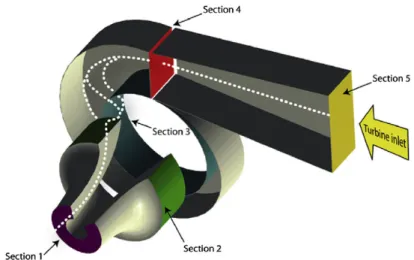
The draft tube is a conduit which connects the runner exit to the tail race where the water is being finally discharged from the turbine. The primary function of the draft tube is to reduce the velocity of the discharged water to minimize the loss of kinetic energy at the outlet. This permits the turbine to be set above the tail water without any appreciable drop of available head. A clear understanding of the function of the draft tube in any reaction turbine, in fact, is very important for the purpose of its design. The purpose of providing a draft tube will be better understood if we carefully study the net available head across a reaction turbine [192].
Figure 1-20 Draft tube
Figure 1-22 Spiral casing
The effective head across any turbine is the difference between the head at inlet to the machine and the head at outlet from it. A reaction turbine always runs completely filled with the working fluid. The tube that connects the end of the runner to the tail race is known as a draft tube and should completely be filled with the working fluid flowing through it. The kinetic energy of the fluid finally discharged into the tail race is wasted. A draft tube is made divergent so as to reduce the velocity at outlet to a minimum. Therefore, a draft tube is basically a diffuser and should be designed properly with the angle between the walls of the tube to be limited to about 8 degree so as to prevent the flow separation from the wall and to reduce accordingly the loss of energy in the tube. Figure 1-23 shows a flow diagram from the reservoir via a reaction turbine to the tail race [192].
The total head 𝐻 at the entrance to the turbine can be found out by applying the Bernoulli's equation between the free surface of the reservoir and the inlet to the turbine as:
𝐻
𝑃
𝜌𝑔
𝑉
2𝑔
𝑧
ℎ
Or 𝐻
𝐻
ℎ
𝑧
Equation 1-5 Where:ℎ = the head loss due to friction in the pipeline connecting the reservoir and the turbine.
Since the draft tube is a part of the turbine, the net head across the turbine, for the conversion of mechanical work, is the difference of total head at inlet to the machine and the total head at discharge from the draft tube at tail race and is shown as H in Figure 1-23:
Figure 1-23 Head across a reaction turbine [192]
Therefore, H = total head at inlet to machine (1) - total head at discharge (3)
𝐻
𝑃
𝜌𝑔
𝑉
2𝑔
𝑧
𝑉
2𝑔
𝐻
𝑉
2𝑔
𝐻
ℎ
𝑉
2𝑔
Equation 1-6The pressures are defined in terms of their values above the atmospheric pressure. Section 2 and 3 in Figure 1-23 represent the exits from the runner and the draft tube, respectively. If the losses in the draft tube are neglected, then the total head at 2 becomes equal to that at 3. Therefore, the net head across the machine is either 𝐻 𝐻 or 𝐻 𝐻 [192]. Applying the Bernoulli’s equation between 2 and 3 in consideration of flow, without losses, through the draft tube, we can write:
𝑃
𝜌𝑔
𝑉
2𝑔
𝑧
0
𝑉
2𝑔
0
𝑃
𝜌𝑔
𝑧
𝑉
𝑉
2𝑔
Equation 1-7Since 𝑉 𝑉 , both the terms in the bracket are positive and hence 𝑃 𝜌𝑔 is always negative, which implies that the static pressure at the outlet of the runner is always below the atmospheric pressure. Equation 1-7 also shows that the value of the suction pressure at runner outlet depends
on z, the height of the runner above the tail race and the decrease in kinetic energy of the fluid in the draft tube. Thevalue of this minimum pressure 𝑃 should never fall below the vapor pressure of the liquid at its operating temperature to avoid the problem of cavitation. Therefore, we finde that the incorporation of a draft tube allows the turbine runner to be set above the tail race without any drop of available head by maintaining a vacuum pressure at the outlet of the runner [192].
1.7.4 Runner of the Francis turbine
The shape of the blades of a Francis runner is complex. The exact shape depends on its specific speed. It is obvious from the equation of specific speed that higher specific speed means lower head. This requires that the runner should admit a comparatively large quantity of water for a given power output and at the same time the velocity of discharge at runner outlet should be small to avoid cavitation. In a purely radial flow runner, as developed by James B. Francis, the bulk flow is in the radial direction. To be clearer, the flow is tangential and radial at the inlet but is entirely radial with a negligible tangential component at the outlet. The flow, in this situation, has to make a 90o turn after passing through the rotor for its inlet to the draft tube. Since the flow area (area perpendicular to the radial direction) is small, there is a limit to the capacity of this type of runner in keeping a low exit velocity. This leads to the design of a mixed flow runner where water is turned from a radial to an axial direction in the rotor itself. At the outlet of this type of runner, the flow is mostly axial with negligible radial and tangential components. Because of a large discharge area (area perpendicular to the axial direction), this type of runner can pass a large amount of water with a low exit velocity from the runner. The blades for a reaction turbine are always shaped in a way that the tangential or whirling component of velocity at the outlet becomes zero 𝑉 0 . This is made to keep the kinetic energy at outlet a minimum.
Figure 1-24 shows the velocity triangles at inlet and outlet of a typical blade of a Francis turbine. Usually the flow velocity (velocity perpendicular to the tangential direction) remains constant throughout, i.e. 𝑉 𝑉 and is equal to that at the inlet to the draft tube.
Figure 1-24 Velocity triangle for a Francis runner [192] The Euler's equation for turbine in this case reduces to:
𝐸
𝑚
𝑒
𝑉 𝑈
Equation 1-8
where, e is the energy transfer to the rotor per unit mass of the fluid. From the inlet velocity triangle shown in Figure 1-24:
𝑉
𝑉 cot 𝛼
Equation 1-9
𝑈
𝑉 cot 𝛼
cot 𝛽
Equation 1-10
Substituting the values of 𝑉 and 𝑈 from Equation 1-9 and Equation 1-10 respectively into Equation 1-8, we have:
𝑒
𝑉 cot 𝛼 cot 𝛼
cot 𝛽
Equation 1-11The loss of kinetic energy per unit mass becomes equal to 𝑉 /2 . Therefore, neglecting friction, the blade efficiency becomes:
𝑒
2𝑉 cot 𝛼 cot 𝛼
cot 𝛽
𝑉
2𝑉 cot 𝛼 cot 𝛼
cot 𝛽
Since 𝑉
𝑉 ∙
Can be written as
1
1
1
2 cot 𝛼 cot 𝛼
cot 𝛽
Equation 1-12The change in pressure energy of the fluid in the rotor can be found out by subtracting the change in its kinetic energy from the total energy released. Therefore, we can write for the degree of reaction:
𝑅
𝑒
1
2 𝑉
𝑉
𝑒
1
1
2 𝑉 𝑐𝑜𝑡 𝛼
𝑒
[since 𝑉
𝑉
𝑉
𝑉
𝑉 𝑐𝑜𝑡 𝛼 ]
Equation 1-13Using the expression of e from Equation 1-11, we have
𝑅
1
cot 𝛼
2 cot 𝛼
cot 𝛽
Equation 1-14The inlet blade angle 𝛽 of a Francis runner varies 45-120° and the guide vane angle 𝛼 from
10-40°. The ratio of blade width to the diameter of runner B/D, at blade inlet, depends on the required
specific speed and varies from 1/20 to 2/3.
Expression for specific speed. The dimensional specific speed of a turbine, can be written as:
𝑁
𝑁𝑃
⁄
𝐻
⁄ Equation 1-15 [192]Power generated P for a turbine can be expressed in terms of available head H and hydraulic efficiency as:
𝑃
𝜌𝑄𝑔𝐻
Equation 1-16 Hence, it becomes:𝑁
𝑁 𝜌𝑄𝑔
⁄𝐻
⁄ Equation 1-17Again, 𝑁
𝑈 /
𝐷
Substituting 𝑈 from Equation 1-10
𝑁
𝑉 cot 𝛼
cot 𝛽
𝜋𝐷
Equation 1-18Available head H equals the head delivered by the turbine plus the head lost at the exit. Thus,
𝑔𝐻
𝑒
𝑉
2
Since 𝑉 =𝑉
𝑔𝐻
𝑒
𝑉 /2
Equation 1-19
with the help of Equation 1-11 it becomes
𝑔𝐻
𝑉 cot 𝛼 cot 𝛼
cot 𝛽
𝑉
2
𝐻
𝑉
2𝑔
1
2 cot 𝛼
cot 𝛽
Equation 1-20
Substituting the values of H and N from Equation 1-20 and Equation 1-18 respectively into the expression 𝑁 given by Equation 1-17, we get:
𝑁
2
⁄𝑔
⁄𝜌
𝑄
⁄ 𝑉𝑓1 1 2⁄𝜋𝐷
cot 𝛼
cot 𝛽
1 2cot 𝛼
cot 𝛽
3 4⁄ Equation 1-21Flow velocity at inlet 𝑉 can be substituted from the equation of continuity as
𝑉
𝑄
𝜋𝐷 𝐵
Equation 1-22where B is the width of the runner at its inlet. Finally, the expression for 𝑁 becomes: 𝑁 2 ⁄ 𝑔 ⁄ 𝜌 ⁄ 𝐵
𝜋𝐷 ⁄ cot 𝛼 cot 𝛽 1 2 cot 𝛼 cot 𝛽 3 4⁄ Equation 1-23
For a Francis turbine, the variations of geometrical parameters like 𝛼 , 𝛽 , 𝐵 𝐷⁄ have been described earlier. These variations cover a range of specific speed between 50 and 400. Figure 1‐25 shows an overview of a Francis Turbine. This figure is shown specifically in order to convey the size and relative dimensions of a typical Francis Turbine to the readers [192].
2 Characteristics of Centrifugal Pumps Working in Direct or Reverse
Mode
2.1 Centrifugal Pumps Working Principle
One of the most common types of pumps used today is the centrifugal pump. This type of pumps uses one or more impellers to utilize the centrifugal force that pushes the process liquid through the pump. Where centrifugal force is the force that exists, when the object or material moves in a circular motion and pushes the object or material outward from the center of rotation [193]. In centrifugal pump what is moving outward is process liquid. They can be grouped into two basic categories: single stage pumps and multi stages pumps.
The centrifugal pumps contain: Inlet, Casing and Outlet. Inside the casing is an impeller. It has a series of curved veins that extend outfit of center. The pump casing is designed so that the area around the impeller creates a gradually widening spiral channel. This widening channel is known as Volute. If we have one impeller and one volute it is called Single stage pump [193].
During the operation a driver rotates the impeller, creating a centrifugal force that throws the liquid process outward into the volute. The outward movement of liquid causes two things to happen: First, it creates a reduced pressure area at the suction eye of the Impeller. There are of lower pressure, draw more liquid into the pump and provide a constant flow of liquid. Second, it causes the liquid to gain speed. This happens because as the liquid is forced to the outside of the rotating impeller, it must move faster to keep up with the impeller. As the liquid flows away from the impeller, it spreads out to fill the volute. The expansion in the volute causes the liquid to slow down and its pressure to increase. The increased pressure moves the liquid through the discharge of the pump and then on through the piping systems of the process one [193].
One way that centrifugal pumps can be categorized by, is how the liquid flows through them. Three common flow path classifications are Radial flows, Axial flows and Mixed flow. In centrifugal pumps that have radial flow design, the impeller causes the liquid to make a 90-degree turn and flow outward or radially from the suction eye to the tips of the veins. A radial flow pump takes
advantage of the maximum amount of centrifugal force that the impeller develops. Generally, radial flow pumps are capable of higher discharge pressure. But they do not move as much liquid as other types of centrifugal pumps [194].
In centrifugal pumps that have an axial flow design, the impeller moves the liquid through the pump along a path that is parallel to the pump shaft. In this type of pump, the liquid moves mainly by the propeller action of the impeller veins. This impeller uses only a small amount of centrifugal force to move the liquid. As a result, the discharge pressure of an axial flow pump tends to be lower than that of a radial flow pump. However, an axial flow pump may be able to move large quantities of liquid [193].
Mixed flow combines the characteristics of radial flow pumps and axial flow pumps. They use centrifugal force and the propeller action of the impeller veins to move the process liquid. For that reason, a mixed flow pump can develop a relatively high discharge pressure and still move a large quantity of liquid [195].
All centrifugal pumps work by creating a centrifugal force. This force moves the liquid through the pump and increases the liquid’s pressure. In applications where large increases in pressure are needed Multistage centrifugal pumps are often being used. A multistage centrifugal pump contains two or more impeller and volutes in a single casing [195].
Regardless of how the impellers on a centrifugal pump are arranged, or how many stages a pump has, the liquid’s pressure increases as it passes through each stage. This creates a Thrust across the impeller in each stage. This thrust known as Axial Thrust is caused by the difference in pressure between the suction eye and the volute. Because there is a difference across the impeller’s axial thrust is created and it tries to push the pump shaft toward the suction eyes. In order for the pumps to operate properly, the thrust must be offset. On some pumps the thrust is offset by using a thrust bearing or a device known as a balanced piston or balance drum. On other pumps the thrust is offset by the arrangement of the impellers [196].
2.2 Centrifugal Pumps Design
2.2.1 System analysis for pump selection
Before a pump can be selected, the application must be clearly defined. The common requirement of all application is to move liquid from one point to another. As pump requirements must match system characteristics, analysis of the overall system is necessary to establish the pump condition. From the information given, the following will ultimately determine pump selection [3].
Capacity range of liquid to be moved Differential head required
NPSHA
Shape of head capacity curve Pump speed
Liquid characteristics Construction
2.2.2 Differential Head required
The head to be generated by the pump is determined from the system head curve. This is graphical plot of the total static head and friction losses for various flow rates. For any desired flow rate, the head to be generated by the pump or pumps, can be read directly (Figure 2-22and Figure 2-33) [3].
Figure 2-2 System head curve[3]
Figure 2-3 The system head curve establishes pump conditions[3]
2.2.3 NPSHA
Net positive suction head available (NPSHA) is of extreme importance for reliable operation. It is the total suction head in feet of liquid absolute, determined at the suction nozzle and referred to datum, less the vapor pressure of the liquid in feet absolute[3].
2.2.4 Shape of Head Capacity Curve
The desired shape of the head capacity (H-Q) curve is determined during analysis of the system. Most specifications call for a continuously rising curve (Figure 2-44) with the percentage rise from the best efficiency point (BEP) determined by system limits and mode of operation. Unstable or hooked curves (Figure 2-5) where the maximum developed head is at some flows greater than zero
are undesirable in applications where multiple pumps operate in parallel. In such applications, zero flow head may be less than system head, making it impossible to bring a second pump on line. It is also possible for pumps to deliver unequal flow rate from another. these legitimate reasons have resulted in many specifications forbidding the use of unstable curves for any application. This is most unfortunate as in many instances such curves are perfectly suitable. More importantly, pumps with unstable curves will develop more head and be more efficient than their continuously rising counterparts. It should be noted that this tendency of instability is normally confined to the lower range of specific speeds. As specific speed increases, the H-Q curve becomes more stable [3].
Figure 2-5 Unstable or hooked head capacity curve.[3]
2.2.5 Pump Speed
Pump speed may be suggested by the user to match electric frequency or available driver speed. However, the pump manufacturer has the ultimate responsibility and must confirm that the desired speed is compatible with NPSHA and satisfies optimum efficiency selection [3].
2.2.6 Liquid Characteristics
To have responsible life expectancy, pump materials must be compatible with the liquid. Since liquids range from clear to those that contain gases, vapors, and solid materials, essential information includes temperature, specific gravity, pH level, solid content, amount of entrained air and/or dissolved gas, and weather the liquid is corrosive. In determining final material selection, the pump manufacturer must also consider operation stresses and effects of corrosion, erosion, and abrasion [3].
2.2.7 General Pump Design
It is not a difficult task to design a centrifugal pump; however, designing the right pump for a specific application related to specific industry and service requires an extensive knowledge of hydraulics. Also, experience with industrial specifications, end users’ and contractors’ special requirements is necessary, as well as many years of practical experience in engineering and marketing [3].
The variables that exist for pump requirements are so numerous that the design of the right pump in the right service is a complex project. There is no such product as the “Universal pump” [3]. As an example, let us take a pump that is required to produce 500 GPM and 200-ft head, rotating at 2 or 4 pole speed. In all industries this hydraulic requirement exists; however, the mechanical specifications are entirely different for each and every industry. For instance, the type of pumps used in publications and papers industry are entirely different from pumps used in the petroleum industry, petrochemical industry, or chemical industry [3]. Thus, the pump required to deliver 500GPM and 200-ft head, will be different for each of the following applications:
Slurry Boiler feed
Pipeline Nuclear Municipal Agricultural Marine Cargo
Mechanical variables include [3]:
Open or closed or semi-open impellers. Single-stage or multi-stage.
Vertical or horizontal.
With water jacket or without. Overhung or two-bearings design. Close-coupled or coupled units. Stiff shaft or flexible shaft design.
Single volute, double volute, quad volute Short elbow-type or turbine-type diffusers. Mechanical seals or packing.
Stuffing boxes with bleed-offs or with clean flush injection. Ball, sleeve, or Kingsbury-type bearing.
Oil rings, forced feed, oil mist, submerged or grease paycheck lubrication.
It can be seen from the variables listed that it is a complex job for a pump designer to design the right pump for the right environment [3].
After complete hydraulic and mechanical specifications have been established, the designer should be ready for pump layout documents [3].
General pump design can be classified in the following categories:
1. Design a new pump to satisfy basics engineering requirements such as shape of H-Q curve, NPSHA, efficiency, etc.
2. Design a new pump to satisfy special applications such as boiler-feed, nuclear coolant, pipeline, large circulator, condensate, secondary recovery, etc.
3. Design a new pump, pulp and paper pumps, building trade pumps, boiler feed pumps, etc. For pumps in any category, an overall performance chart should be prepared (if not available) as a first step in design study. This chart will establish the flow and head for each pump, establish the number and size of pumps required to satisfy the range chart, and avoid overlap or gaps between pump sizes. Even if only one pump is required, the range chart should be confronted to be sure that the new pump fits into the overall planning [3].
Figure 2-6 poorly planned performance chart [3]
Many old pump lines have poorly planned range charts, resulting in similar pump overlaps and uncovered gaps between pump sizes, such as in the chart shown in Figure 2-66. Black dots show pumps that could be eliminated, permitting a substantial reduction in inventory without hurting overall hydraulic performance. This type of chart is not recommended. A suggested, properly laid out performance range chart is shown in Figure 2-77. Steps to develop this chart will now be described [3].
1. Establish BEP of lowest capacity and lowest head pump required. In this example, this is 86 GPM, 150-ft head. Which is achieved by a 1-in. Pump, and a 7-in. Diameter impeller.
2. Extend BEP capacity coverage at a constant 150-ft head by multiplied of 1.75 Thus, second pump BEP = 86 GPM * 1.75 = 150 GPM.
Third pump BEP = 150 GPM * 1.75 = 260 GPM, etc. In this manner, the base line BEP is established.
3. Establish next size pump by multiplying each base line BEP by GPM * 1.75
Head * 1.45
4. For all additional pump BEPs, multiplying preceding pump flow by 1.75 and head by 1.45.
The constants 1.75 and 1.45 are recommended for a well-planned performance chart following a number of constant specific speed lines. There are no gaps between pumps. each performance block can be covered by normal impeller trim, and there are no overlaps. The chart is also helpful to the designer. In this example, only six small pumps have to be designed and test checked [3].
Figure 2-7 recommended performance chart [3]
The other sizes that follow specific speed lines can be factored up and their performance accurately predicted. Designed and tested checked. After the hydraulic performance chart is
complete, the designer should check the mechanical requirements as outlined by the applicable industrial specifications [3].
If a complete line is being designed, the following mechanical features should be checked: Shaft size
Bearing arrangements Stuffing box design
Bolting for maximum pressures Suction pressure
Pump axial and radial balance Bed plates, motor support, etc. Gasketing
Lubrication
The standardization and the use of existing parts should be considered at this time; however, hydraulic performances should never be sacrificed for mechanical or cost reasons. If sacrifice becomes necessary, adjust pump hydraulics accordingly [3].
2.3 Energy efficiency optimization in water distribution systems
2.3.1 Introduction
The operation of Water Distribution Systems generally requires high amounts of energy, which vary in relation to the characteristics of the served area, but also in design and management choices. The assessment of energy efficiency in water distribution systems is strongly influenced by the nature site-dependent of the water-energy nexus in pressurized networks. Understanding this link requires a systematic energy analysis to evaluate separately the influence of pumping stations, network, and water loss. Such an analysis can allow to highlight inconsistencies in the design and management that are reflecting on both the resources, water and energy [29].
2.3.2 Energy Efficiency Indicator for water networks
The growing attention brought to the so-called water-energy nexus is certainly driven by the non-negligible amount of energy required for operating water distribution systems. That is, energy-related aspects arise in water network, when one or more electromechanical devices (pumps) are present. Needless to say, the interest towards energy involves environmental, but especially cost issues. This should be kept in mind, while trying to find the most appropriate way for assessing (or improving) the energy efficiency of a given water system, because on the one hand there is the actual energy consumed, on the other hand there is the way that energy is properly or improperly spent. Finally, both aspects always need to be considered in conjunction with the level of service provided [29].
The Unavoidable Minimum Energy required (UME) is computed at each device and involves the definition of a reference hydraulic head (𝐻 ) [29].
𝐻 is the minimum head to be granted at the downstream section of each pump, in order to satisfy the given level of service (namely, a minimum pressure value) throughout the network, during the whole day, considering that no leakages occur [29]. Therefore:
𝑈𝑀𝐸
𝛾 ∙ 𝑊 ∙ 𝐻
𝐻
/3600000
Equation 2-1 [29]
where UME is the unavoidable minimum energy required at the pump (kWh); is the specific gravity of water (N/𝑚 ); W is the total volume lifted by the pump (𝑚 ) over the considered period; 𝐻 is the above defined reference head (m) at the downstream section of the pump; 𝐻 is the average hydraulic head at the upstream section of the pump (m) [29].
The ratio between UME and the energy actually consumed 𝐻 , gives birth to the Energy Efficiency Indicator (EEI):
𝐸𝐸𝐼
𝑈𝑀𝐸
𝐸
Equation 2-2 [29]The 𝐻 calculation has required the following steps: pump closed; downstream end of the pump replaced by a “virtual” reservoir; all the emitters’ coefficients set to zero; pipe leading to the tank closed. The 𝐻 value for the assigned network is found by decreasing the hydraulic head of the virtual reservoir iteratively, until the minimum pressure at the nodes is met [29].
The 𝐸 value is assessed on a daily basis:
𝐸
𝐸
Δ𝐸
𝐸
∙ ∙Equation 2-3 [29]
where 𝐸 is the energy consumed by the pump, considering its electro-mechanical efficiency (kWh); A is the cross sectional area of the tank (m2); 𝐻 and 𝐻 are the hydraulic heads in the tank (m), respectively at time 0:00 and 24:00; HP and η are respectively the average pump head and the average efficiency of the pump [29].
3 Micro-Hydro Generators using Pump as Turbine
3.1 Introduction to Micro-Hydro Generators
The basic principle of hydropower is that if water can be piped from a certain level to a lower level, then the resulting water pressure can be used to do work. If the water pressure is allowed to move a mechanical component, then that movement involves the conversion of the potential energy of the water into mechanical energy. Hydro turbines convert water pressure into mechanical shaft power, which can be used to drive an electricity generator, a grinding mill or some other useful device [197].
Hydropower is a very clean source of energy. It does not consume but only uses the water, after use it is available for other purposes (although on a lower horizontal level). The conversion of the potential energy of water into mechanical energy is a technology with a high efficiency (in most cases double that of conventional thermal power stations) [197].
The use of hydropower can make a contribution to savings on exhaustible energy sources. Each 600 kWh of electricity generated with a hydro plant is equivalent to 1 barrel of oil (assuming an efficiency of 38 % for the conversion of oil into electricity) [197].
The main advantages of hydropower are:
power is usually continuously available on demand,
given a reasonable head, it is a concentrated energy source, the energy available is predictable,
no fuel and limited maintenance are required, so running costs are low (compared with diesel power) and in many cases imports are displaced to the benefit of the local economy, it is a long-lasting and robust technology; systems can last for 50 years or more without
major new investments.
it is a site-specific technology for sites that are well suited to the harnessing of water power and are also close to a location where the power can be economically exploited, which is not very common,
there is always a maximum useful power output available from a given hydropower site, which limits the level of expansion of activities which make use of the power,
river flows often vary considerably with the seasons, especially where there are monsoon-type climates and this can limit the firm power output to quite a small fraction of the possible peak output,
lack of familiarity with the technology and how to apply it inhibits the exploitation of hydro resources in some areas.
To know the power potential of water in a river it is necessary to know the flow in the river and the available head. The flow of the river is the amount of water (in 𝑚 or liters) which passes in a certain amount of time a cross section of the river. Flows are normally given in cubic meters per second (𝑚 /s) or in liters per second (l/s). Head is the vertical difference in level (in meters) the water falls down [198].
Figure 3-1 [198]
The theoretical power (P) available from a given head of water is in exact proportion to the head H and the flow Q [197].
P=Q × H × c c = constant
Equation 3-1 The theoretical power
The constant c is the product of the density of water and the acceleration due to gravity (g). If P is measured in Watts, Q in m3/s and H in meters, the gross power of the flow of water is:
P=1000 × 9.8 × Q × H
Equation 3-2 the gross power of the flow of water [197]This available power will be converted by the hydro turbine in mechanical power. As a turbine has an efficiency lower than 1, the generated power will be a fraction of the available gross power [197].
Hydropower installations can be classified as follows (Table 3-1): Table 3-1 Hydropower installations [197]
Name Description
Large All installations with an installed capacity of more than 1000 kW (according to some definitions more than 10,000 kW).
Small General term for installations smaller than 1000 kW (or < 10,000 kW). Also used for installations in the range between 500 and 1000 kW.
Mini Capacity between 100 and 500 kW.
Micro Hydropower installations with a power output less than 100 kW (or less than 1000 kW).
Definitions of small, mini, and micro hydro plants found in literature (Table 3-2):
Table 3-2 Source: Moreire, J.R. & Poole, A.D. (1993) Hydropower and its constraints. In: Johansson T.B. et al, (1993) Renewable energy: sources for fuels and electricity (ISBN 1-85383-155-7)
Country Micro (kilowatts) Mini (kilowatts) Small (megawatts)
United States < 100 100 – 100 1 - 30 China - < 500 0.5 – 25 Russia < 100 - 0.1 – 30 France 5-5000 - - India < 100 101 – 1000 1 – 15 Brazil < 100 100 – 1000 1 – 30 Norway < 100 100 – 1000 1 – 10
various < 100 < 1000 <10
3.2 PATs (Pump as Turbine)
Running pumps as turbines is a well-known concept in the water supply industry. It is seen as an efficient method of generating power as well as recovering energy and contributing to savings. The concept of running a centrifugal pump in reverse rotation mode has been recognized by pump manufacturers for many years and within the water supply industry this concept has been exploited to a limited degree as a means of generating power in locations where it is considered too expensive to purchase a hydro turbine. It has not gone unnoticed by water suppliers, operators of small hydropower plants and pump manufacturers that running pumps as turbines (PATs) is an efficient method of generating energy as well as recovering energy and contributing to energy savings. In the current economic climate, where reducing energy costs is becoming a high priority, it is not surprising that PATs are starting to create significant interest [199].
Using pump as turbine is an attractive and significant alternative. Pumps are relatively simple machines with no special designing and are readily available in most developing countries. Besides, their installation, commissioning and maintenance are easy and cheap. From the economical point of view, it is often stated that the capital payback period of PATs in the range of 5–500 kW is two years or less [199].
3.3 PATs working principle
In recent years, small and micro hydro power plants have become a possible new application area for PAT, which are aimed at replacing the more expensive conventional turbines. One way of overcoming the high-cost capital price of Micro/Pico hydropower stations is to use simple machines instead of more complex conventional turbines. Industrial pumps can be effectively operated as turbines. From the economic point of view, it is often stated that pumps working as turbines, in the range of 1–500 kW, allow capital payback periods of two years or less, a considerably shorter time than that of a conventional turbine [4].
Several researchers have become interested in pumps operating as turbines for many types of small applications. Pump manufacturers do not normally provide turbine mode performance for their products. Therefore, in recent years, many prediction techniques have been developed e.g. Sharma [5], Williams [6] , Alatorre-Frenk [7], and more recently Ramos and Borga [8], [9], Valadas and Ramos [10], Singh [11], [12], Yang et al. [13], and Derakhshan and Nourbakhsh [14].
Due to the huge number of pumps on the market all possible sizes, appropriate machines, cheap and reliable, are readily available. Regarding maintenance, there are many advantages compared with custom-made turbines.
As a result of the fixed geometric conditions within the casing and impeller, pumps as turbines have a low part-load performance. This characteristic address one of the most important challenges for a Micro-Hydro system based on a PAT. A pump operating as a turbine is very sensitive towards changing boundary parameters, namely head and discharge. Hence, a wrong pump selection or rotational speed will result in a shift of the operating point, delivering a non-desired output, and ultimately even causing a possible failure of the project [2].
Figure 3-2 Typical performance curves for PAT for various rotational speeds [2]
Centrifugal pumps can be easily rotated as turbines in heads ranging from 15 to100 m and with flow rates ranging from 5 to 50 l/s (Figure 3-2). Figure 3-4 shows the application of different pumps working as turbines. Cross flow turbines can be replaced by centrifugal, mixed flow and double suction PATs. The ranges for mixed flow PATs are 5–15 m and 50–150 l/s for head and flow rates, respectively. For heads ranging from 15 to 100 m and flow rates ranging from 50 to 1000 l/s, double suction pumps or multi centrifugal pumps in a parallel arrangement are suitable.
Pump manufacturers usually produce centrifugal and mixed flow pumps on a large scale, so these pumps are readily available on the market at a low price [4].
Figure 3-3 A centrifugal PAT-based pico hydropower station, installed in the West of Iran [4]
Figure 3-4 Application of various pumps as turbines [4]
Figure 3-5 An axial PAT based micro hydropower station, installed in the North of Iran [2]
When a pump runs as a turbine, the high-pressure fluid enters the machine and then leaves after the conversion of the energy has occurred within the impeller. Since the flow direction and the
rotational speed are reverse, the velocity triangles of both modes change. Although only the shaft rotation and flow direction are opposite in pump and turbine modes, their velocity triangles are different [2].
Considerations show that the inlet flow angle to the impeller in a PAT is not exactly the same as the outlet flow angle of the impeller in the pump mode. This angle (av) is approximately equal to the volute angle. In fact, the volute operates as a guide channel in turbine mode. Assuming the outlet flow angle from the impeller in reverse operation is equal to the impeller inlet flow angle in direct operation (i.e. with no whirl at the impeller exit), the same Euler heads for both modes can be considered [2].
3.4 PAT Applications
Nowadays, applications of PAT have been developed in villages, farms, irrigation systems, as pressure dropping valves and as small pump storage power stations. Since 1930, the main challenge in PAT usage was the selection of a proper PAT for a small hydro-site. Several case studies of applications of PAT will be reviewed in CHAPTER 4 and CHAPTER 5.
3.5 Components of PATs
Depending on the PAT type, the components of each machine are different. However, in general, PAT components are classified in two groups: rotary and stationary. The rotary group consists of the impeller and shaft. The stationary group includes the inlet parts (i.e., the inlet pipe and volute), outlet parts (i.e., the suction pipe and draft tube), and the casing and mechanical parts (i.e., rings, mechanical seals and bearings). However, the main hydraulic parts of a PAT are the impeller, volute and draft tube (Figure 3-6) [15].
Figure 3-6 PAT components (www.processindustryforum.com)
3.5.1 The Volute
Although the volute of a PAT is designed to collect the water from the impeller of a pump, the design method for a pump is quite similar to a Francis turbine volute (i.e. a constant velocity method). Therefore, when the flow is reverse, the volute of a PAT will work properly as a distributor of the flow surrounding the impeller. However, the most important role of a volute is the balancing of radial pressure and forces. Figure 3-6 shows a typical volute of a PAT [200]. (Figure 3-7)
3.5.2 The Impeller
The impeller, the main component of a PAT, converts the hydraulic energy of the inlet flow to the mechanical shaft. Although the impeller has been designed to pressurize the liquid using the centrifugal force, it can also absorb the flow energy with a reasonable efficiency. The impeller usually has 5–8 blades, with a hydrofoil shape type [200]. An impeller and the details of a blade are presented in Figure 3-8.
Figure 3-8 Impeller and details of a blade [15]
3.5.3 The Draft Tube
A small kinetic energy is required at the PAT outflow to minimize energy losses. Using a draft tube, the kinetic energy can be converted into potential energy. Therefore, a draft tube is designed based on the maximum conversion of velocity to pressure (according to the Bernoulli equation).Figure 3-9 shows a typical draft tube of a PAT [200].
Figure 3-9 Draft tube of a PAT [15]
3.6 A state-of-the-art review on PAT
Hydropower is a renewable energy source based on the natural water cycle, and actually the most mature, reliable and cost-effective renewable power generation technology available [86]. It contributes to around 16% of the World electricity supply generated from about 20,053 TW h of installed capacity [87]. In many countries it is the main source of power generation e.g. Norway – 99%, Brazil – 86%, Switzerland – 76% and Sweden – 50% [88].
While large hydropower plants feed the national grid, typical off grid micro hydropower plant (MHP) is the most popular solution for electrification among rural communities, supplying the power in the range of 5–100 kW, usually using a run-of-the-river to divert some of the water from the river before dropping into a pressurized penstock [89].
However, in accordance with individual countries’ administrative purposes [90],[91], hydropower plants have been classified in terms of head or installed capacity, with different upper and lower limits for each category. Table 3-3 shows one of the used classifications as found in the literature.
Table 3-3 Hydropower scheme classification. [85]
The mostly met problem in micro turbines is their higher price compared to full scale ones with respect to the whole project budget, owing to their expensive manufacturing price. For instance, it's very difficult, time-consuming, and costly to develop such site-specific turbines in accordance with the local ecology [91].
The cost of electro-mechanical components in large hydro-power plants is around 20% but in MHPs it is relatively high and varies from 35% to 40% of the total project cost which may rise even up to 60% or 70% of the total project cost in some typical cases [92] Figure 3-10.
the first pump turbine had been set at a remote farm in the Yorkshire Dales of the North England in 1930. This scheme has been working for a five-year testing time, after which its reliability was confirmed before being transferred to other countries [93]. From then on, pump turbine has become a hot topic amongst researchers and field engineers, where indeed, it has been used at so many sites, mainly for electricity provision in remote hilly regions away from central grid reach (Table 3-4).
Table 3-4 PAT installations [85]
Different researchers; Williams [93], Orchard and Sander [94], Ramos and Borga [95], Derakhshan and Ahmad [21], and Arriaga [96] among others, have provided information about the applications and advantages of a pump working as a turbine, mainly basing their arguments on its two most important features: “cost-effectiveness” and “simplicity”. Adding on the third one, “smallness”, which is also true in a way; However, owing to the philosophy behind the pump's functioning difference between conventional and reverse modes, pump turbines flow dynamics and operational characteristics have not been fully understood, thus requiring more research efforts in the same. As a matter of fact, many researchers have tried different PAT efficiency prediction methods but in vain, as the predicted results never got validated through experimentation, with errors of the order of ± 20% [97], and couldn’t cover a wide range of pump operating conditions in reverse mode. PAT's simple structural design would reflect its easily understandable operations.
3.6.1 Pump-turbine selection
Typical micro hydropower plants convert the falling water-contained energy to mechanical energy by turning the pump turbine, which converts the water pressure into mechanical shaft power to
drive an electric generator. The power available is proportional to the product of head and volume flow rate as the general formula for hydropower systems shows [98]:
𝑃
𝑔𝑄𝐻
Equation 3-3
where P is power output, η hydraulic efficiency, ρ fluid density, g gravitational acceleration, Q volumetric flowrate and H water head. As shown in Equation 3-3, the turbine selection process for a MHP of interest, should be based on the head and flowrate available at the site. The power output may also be related to the head to express the turbine specific speed.
𝑁
𝑛𝑃
/𝐻
/ Equation 3-4where Ns is the turbine specific speed and n is the real rotation speed of turbine. This parameter characterizes the turbine runner, spiral casing, blade shape and other geometric design features, thus doesn’t depend on the size but the shape of the machine of concern [91]. For instance, two machines of similar shape and different size may have same specific speed.
Different researchers; Orchard and Sander [94], Franc et al. [99], Chapallaz et al. [100], Fraenkel et al. [101] and Paish [98] among others, have so far provided head-flow charts depicting the range of application for different PATs (Figure 3-11).
![Figure 1-16 Draft Tube [190] 1.6.4 Power and efficiencies:](https://thumb-eu.123doks.com/thumbv2/123dokorg/7399643.97666/26.918.163.713.79.420/figure-draft-tube-power-efficiencies.webp)
![Figure 1-17 A Francis turbine [192] A Francis turbine comprises mainly of four components:](https://thumb-eu.123doks.com/thumbv2/123dokorg/7399643.97666/27.918.264.630.599.997/figure-francis-turbine-francis-turbine-comprises-mainly-components.webp)
![Figure 3-17 Four quadrant characteristics of a reversible pump turbine a) Flow-speed curve [139]](https://thumb-eu.123doks.com/thumbv2/123dokorg/7399643.97666/76.918.299.622.107.618/figure-quadrant-characteristics-reversible-turbine-flow-speed-curve.webp)
![Figure 4-1 Head ratios of the tested PATs with various pump specific speeds [20]](https://thumb-eu.123doks.com/thumbv2/123dokorg/7399643.97666/81.918.255.652.414.648/figure-head-ratios-tested-pats-various-specific-speeds.webp)
![Figure 4-4 Proposed 3D representation for PAT efficiency estimation against the real efficiency of selected machines [28]](https://thumb-eu.123doks.com/thumbv2/123dokorg/7399643.97666/83.918.278.649.333.940/figure-proposed-representation-efficiency-estimation-efficiency-selected-machines.webp)
![Figure 4-7 Discharge ratios of tested PATs with various pump maximum efficiencies [20]](https://thumb-eu.123doks.com/thumbv2/123dokorg/7399643.97666/84.918.328.583.727.881/figure-discharge-ratios-tested-pats-various-maximum-efficiencies.webp)
![Figure 4-16 Outline of the volute geometry. [23] The angle](https://thumb-eu.123doks.com/thumbv2/123dokorg/7399643.97666/98.918.238.673.119.391/figure-outline-volute-geometry-angle-.webp)

![Figure 4-31 Comparison, for the PATs 40e250 (left side) and 50e160 (right side), between experimental data and numerical simulations (new model e dashed line e and old model [23]](https://thumb-eu.123doks.com/thumbv2/123dokorg/7399643.97666/106.918.126.812.440.679/figure-comparison-pats-right-experimental-numerical-simulations-dashed.webp)
