Università Politecnica delle Marche
Corso di Dottorato in Ingegneria Civile, Ambientale, Edile ed Architettura ---
The role of soil-structure interaction in
interpretation of vibration measurements
on continuous viaducts
Ph.D. Dissertation of:
Marco Regni
Advisor:
Prof. Ing. Luigino Dezi
Co-Advisor:
Prof. Ing. Fabrizio Gara
Curriculum Supervisor:
Prof. Ing. Stefano Lenci
Università Politecnica delle Marche Facoltà di Ingegneria
Dipartimento di Ingegneria Civile, Edile ed Architettura Via Brecce Bianche – 60131 – Ancona, Italia
Acknowledgments
I wish to thank Professor Fabrizio Gara, Sandro Carbonari and Francesca Dezi for their time and patience and for the great opportunity to work with them during these years.
I would like to thank Francesca Dezi for her important support in the geotechnical issues. I am thankful to Davide Roia for his support during all my PhD activity.
I would like to thank Professor Luigino Dezi and Fabrizio Gara for giving me the chance to accomplish this PhD course.
I would like to thank the laboratory technicians (Enzo D’Aria, Stefano Bufarini, Franco Rinaldi and Andrea Conti) for their skills and support during these years.
Finally, I would like to thank all the PhD of the Department I.C.E.A for supporting me through these years (Michele Morici, Maria Chiara Capatti, Vanni Nicoletti, Laura Gioiella, Fabrizio Scozzese, Lucia Minnucci, Fabio Micozzi, Claudia Canuti and Davide Arezzo).
Contents
Contents ... ii
List of Figures ... iv
List of Tables ... viii
Abstract ... 1
Sommario ... 2
Introduction ... 3
Chapter 1. Ambient Vibration Tests (AVTs) ... 6
Chapter 2. Soil Structure Interaction (SSI) ... 8
2.1. SSI Direct approach ... 9
2.2. SSI Substructure approach ... 11
2.3. Lumped parameter model for time-domain analysis ... 14
Chapter 3. Viaduct descriptions ... 19
3.1. “Chiaravalle Viaduct” – Chiaravalle (AN), Italy ... 19
3.1.1. Position and main features ... 19
3.1.2. Site characterization ... 23
3.2. “Paglia bridge” - Orvieto (TR), Italy ... 26
3.3. “Cesano bridge” - Corinaldo (AN), Italy ... 27
Chapter 4. Description of AVTs on the viaducts ... 29
4.1. “Chiaravalle viaduct” tests ... 29
4.1.1. Introduction ... 29
4.1.2. Configuration KC1 ... 31
4.1.3. Configuration KC2 ... 35
4.1.4. Configuration KC4 ... 37
4.1.5. Configuration P3... 39
4.1.6. Tests after retrofitting works ... 43
4.2. “Paglia bridge” – Orvieto (TR), Italy ... 52
4.2.2. Configurations Conf-1 and Conf-2 ... 53
4.2.3. Configurations P1 ... 59
4.3. “Cesano” bridge - Corinaldo (AN), Italy ... 64
4.3.1. Introduction ... 64
4.3.2. Configurations Conf-1 and Conf-2 (global behaviour) ... 67
4.3.3. Piers P1 and P2 (Step1) ... 74
4.3.4. Piers P1 and P2 (Step 2) ... 78
4.3.5. Piers P1 and P2 (Step 3) ... 81
Chapter 5. Numerical modelling ... 84
5.1. “Chiaravalle viaduct” Finite Element Model ... 84
5.1.1. General ... 84
5.1.2. Lamped Parameter Models (LPMs) ... 85
5.1.3. Soil-Foundation modelling ... 87
5.1.4. SSI model accounting for spatial variability of stratigraphy and pile-soil-pile interaction ... 87
5.1.5. SSI model accounting for pile-soil-pile cap interaction ... 92
5.1.6. Simplified modelling of soil-pile interaction ... 95
5.1.7. Rocking foundation of pier P3, for different models ... 96
5.2. “Paglia bridge” Finite Element Model ... 100
5.2.1. General ... 100
5.2.2. Comparison between experimental and analytical results ... 100
5.3. “Cesano bridge” Finite Element Model ... 101
5.3.1. General ... 101
5.3.2. Comparison between experimental and analytical results ... 104
5.3.3. Rocking foundation of piers, for different steps ... 105
Chapter 6. Comparison of experimental and numerical modal parameters ... 108
Conclusion ... 115
List of Figures
Figure 1.1 Fields of application of Ambient Vibration Tests ... 6
Figure 2.1 Simple scheme of SSI direct approach ... 9
Figure 2.2 Scheme in subsystems of a soil-foundation-superstructure system ... 9
Figure 2.3 Simple scheme of SSI substructures approach ... 12
Figure 2.4 Scheme in subsystems EG in SSI substructure approach ... 13
Figure 2.5 Scheme in subsystems S in SSI substructure approach ... 14
Figure 2.6 Soil-foundation system ... 15
Figure 2.7 Scheme of the adopted LPM ... 17
Figure 3.1 Geographic position of the viaduct (from Google Maps) ... 19
Figure 3.2 Plane location of KCs ... 20
Figure 3.3 (a) Cross section of the viaduct and column bent pier, (b) wall pier ... 20
Figure 3.4 Dimensions of the viaduct cross section, including foundations ... 21
Figure 3.5 Dimensions of the P17 cross section, including foundations ... 22
Figure 3.6 Geolithological map ... 23
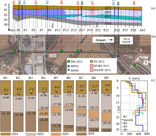
Figure 3.7 (a) Soil geological profile; (b) position of the test site and geotechnical surveys; (c) soil profiles from borehole investigations and shear wave velocities within the deposit. ... 24
Figure 3.8 HVRS plot obtained from in situ tests ... 25
Figure 3.9 Lateral views of “Paglia bridge”, Orvieto ... 26
Figure 3.10 Dimensions of the “Paglia bridge” cross section ... 27
Figure 3.11 Geographic position of the “Cesano bridge” (from Google Maps) ... 27
Figure 3.12 Global view of “Cesano bridge” ... 27
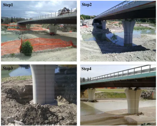
Figure 3.13 Images of the “Cesano bridge” piers at different construction steps ... 28
Figure 4.1 Photos of the instrumentation setup ... 30
Figure 4.2 KC1 Configurations: (a) KC1-1, (b) KC1-2 ... 31
Figure 4.3 Stabilization Diagram of the KC1 Configurations (KC1-1 and KC1-2)... 32
Figure 4.4 First three mode shapes of KC1 ... 33
Figure 4.5 Higher mode shapes of KC1 involving pier P3 ... 34
Figure 4.6 Auto MAC of KC1 ... 34
Figure 4.7 KC2 Configuration ... 35
Figure 4.8 Stabilization Diagram of the KC2 Configuration ... 35
Figure 4.9 First three mode shapes of KC2 ... 36
Figure 4.10 Auto MAC of KC2 ... 36
Figure 4.11 KC4 Configuration ... 37
Figure 4.12 Stabilization Diagram of the KC4 Configuration ... 37
Figure 4.13 First three mode shapes of KC4 ... 38
Figure 4.14 Auto MAC of KC4 ... 38
Figure 4.16 Accelerometers photos placed in P3 Configuration ... 40
Figure 4.17 Stabilization Diagram of the P3 Configuration ... 40
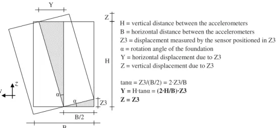
Figure 4.18 Simplified scheme of the rigid displacements due to the rocking for “Chiaravalle viaduct” ... 41
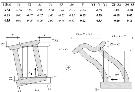
Figure 4.19 Contributions to the modal displacements: (a) foundation rigid translation and rocking and (b) pier deflection ... 41
Figure 4.20 Comparison between P3 and foundation rocking ... 42
Figure 4.21 “Chiaravalle viaduct” view after retrofitting works ... 43
Figure 4.22 Piers after retrofitting works... 43
Figure 4.23 “Chiaravalle viaduct” Configurations: (a) Conf-1, (b) Conf-2, (c) Conf-3 ... 44
Figure 4.24 Stabilization Diagram of the “Chiaravalle viaduct” (1, 2 and Conf-3) ... 45
Figure 4.25 First three mode shapes of KC1 ... 48
Figure 4.26 First three mode shapes of KC2 ... 48
Figure 4.27 First three mode shapes of KC4 ... 49
Figure 4.28 MAC of (a) KC1, (b) KC2, (c) KC4 ... 49
Figure 4.29 Contributions to the modal displacements: (a) foundation rigid translation and rocking and (b) pier deflection ... 50
Figure 4.30 “Paglia bridge” configurations: (a) Configuration Conf-1, (b) Configuration Conf-2 ... 52
Figure 4.31 Stabilization Diagram of the bridge configurations: (a) Conf-1, (b) Conf-2 .... 53
Figure 4.32 Views of the 1°Mode shape ... 56
Figure 4.33 Views of the 2°Mode shape ... 56
Figure 4.34 Views of the 3°Mode shape ... 56
Figure 4.35 Views of the 4°Mode shape ... 57
Figure 4.36 Views of the 5°Mode shape ... 57
Figure 4.37 Views of the 6°Mode shape ... 57
Figure 4.38 Views of the 7°Mode shape ... 58
Figure 4.39 Views of the 8°Mode shape ... 58
Figure 4.40 Views of the 9°Mode shape ... 58
Figure 4.41 Auto MAC of “Paglia bridge” ... 59
Figure 4.42 P1 Configuration ... 60
Figure 4.43 Stabilization Diagram of the P1 Configuration ... 61
Figure 4.44 Simplified scheme of the rigid displacements due to the rocking for “Paglia bridge” ... 61
Figure 4.45 Contributions to the modal displacements: (a) foundation rigid translation and rocking and (b) pier deflection ... 62
Figure 4.46 Comparison between 15AY and foundation rocking ... 62
Figure 4.47 “Cesano bridge” configurations: (a) Configuration Conf-1, (b) Configuration Conf-2 ... 64
Figure 4.48 P1 and P2 Configurations (Step1) ... 65
Figure 4.49 Photos of the instrumentation setup ... 66
Figure 4.50 Stabilization diagram of “Cesano bridge” configurations (Step 1): (a) Conf-1, (b) Conf-2 ... 67
Figure 4.51 Views of the 1°Mode shape ... 69
Figure 4.52 Views of the 2°Mode shape ... 69
Figure 4.54 Views of the 4°Mode shape ... 70
Figure 4.55 Views of the 5°Mode shape ... 70
Figure 4.56 Views of the 6°Mode shape ... 71
Figure 4.57 Views of the 7°Mode shape ... 71
Figure 4.58 Views of the 8°Mode shape ... 71
Figure 4.59 Views of the 9°Mode shape ... 72
Figure 4.60 Auto MAC of “Cesano bridge” ... 72
Figure 4.61 P1 and P2 Configurations (Step1) ... 74
Figure 4.62 Stabilization Diagram: (a) piers configuration, (b) global configuration ... 76
Figure 4.63 Simplified scheme of the rigid displacements due to the rocking for “Cesano bridge” ... 76
Figure 4.64 Contributions to the modal displacements “Cesano bridge” (Step1): (a) foundation rigid translation and rocking and (b) pier deflection ... 77
Figure 4.65 P1 and P2 Configurations (Step2) ... 78
Figure 4.66 Simplified scheme of the rigid displacements due to the rocking for “Cesano bridge” ... 79
Figure 4.67 Contributions to the modal displacements “Cesano bridge”: (a) foundation rigid translation and rocking and (b) pier deflection ... 80
Figure 4.68 P1 and P2 Configurations (Step3) ... 81
Figure 4.69 Simplified scheme of the rigid displacements due to the rocking for “Cesano bridge” ... 82
Figure 4.70 Contributions to the modal displacements “Cesano bridge”: (a) foundation rigid translation and rocking and (b) pier deflection ... 83
Figure 5.1 Fixed Base model (FB): (a) global view, (b) detail of one pier ... 85
Figure 5.2 Scheme of the adopted LPM ... 86
Figure 5.3 3D finite element model without not including the pile-cap interaction ... 88
Figure 5.4 Comparison between impedances from different models ... 89
Figure 5.5 Compliant base models (CB-P and CB-P&C): (a) global view, (b) detail of one pier ... 89
Figure 5.6 Comparison of foundation impedances obtained from Dezi et al. at different piers and impedances of LPM of P3 ... 91
Figure 5.7 Amplitude of displacements at P3, P12 and P19 obtained from tailored LPMs and the LPM of P3 ... 92
Figure 5.8 3D finite element model including the pile-cap interaction ... 93
Figure 5.9 Comparison of foundation impedances adopted for the CB-P and CB-P&C models ... 94
Figure 5.10 Conventional soil-structure interaction model (CB-CONV): (a) global view, (b) detail of one pier ... 95
Figure 5.11 P3 Configuration in Fixed base model (FB): (a) P3 position, (b) displacements layout ... 96
Figure 5.12 Contributions to the modal displacements: (a) foundation rigid translation and rocking and (b) pier deflection ... 97
Figure 5.13 P3 Configuration in Compliant base model (CB-P and CB-P&C): (a) P3 position, (b) sensor layout ... 97
Figure 5.14 P3 Configuration in Conventional base model (CB-CONV): (a) P3 position, (b) sensor layout ... 98
Figure 5.15 Conventional model of “Paglia bridge”: (a) global view, (b) detail of one pier
... 100
Figure 5.16 Conventional model of “Cesano bridge”: (a) global view, (b) detail of one pier ... 101
Figure 5.17 Sensitivity study of frequency variance according to the excavation depth (a) First bending mode; (b) First transversal mode ... 105
Figure 5.18 Configuration layout of P1 in “Cesano bridge”: (a) global view, (b) detail of one pier ... 106
Figure 5.19 Contributions to the modal displacements “Cesano bridge”: (a) foundation rigid translation and rocking and (b) pier deflection ... 107
Figure 6.1 (a) Mean displacement amplitudes obtained from the CB-P&C model; (b) stabilization diagrams of KC1, KC2 and KC4 ... 109
Figure 6.2 Comparison of numerical and experimental mode shapes ... 111
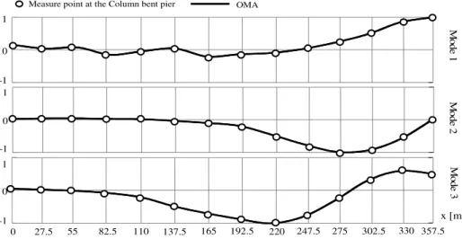
Figure 6.3 Modal displacements of pier P3 in “Chiaravalle viaduct” ... 112
Figure 6.4 Modal displacements of pier P1 in “Orvieto bridge” ... 113
List of Tables
Table 1. Height of the piers... 20
Table 2. Mechanical properties of concrete ... 21
Table 3. Mechanical and dynamic parameters ... 25
Table 4. Modal parameters of KC1-1 ... 32
Table 5. Modal parameters of KC1-2 ... 32
Table 6. Modal parameters of KC1 (PoSER) ... 33
Table 7. Modal parameters of KC2 ... 35
Table 8. Modal parameters of KC4 ... 38
Table 9. Modal parameters of P3 ... 40
Table 10. Rigid displacements of P3 due to the rocking ... 41
Table 11. Rigid displacements of P3 compare with foundation rocking ... 42
Table 12. Modal parameters of Conf-1 ... 45
Table 13. Modal parameters of Conf-2 ... 46
Table 14. Modal parameters of Conf-3 ... 46
Table 15. Modal parameters of KC1 after retrofitting works (PoSER) ... 47
Table 16. Modal parameters of KC2 after retrofitting works (PoSER) ... 47
Table 17. Modal parameters of KC3 and KC4 after retrofitting works (PoSER) ... 47
Table 18. Rigid displacements of P3 due to the rocking ... 50
Table 19. Progressive distances of the accelerometers from Ab1 ... 53
Table 20. Modal parameters of Conf-1 ... 54
Table 21. Modal parameters of Conf-2 ... 54
Table 22. Modal parameters of “Paglia Bridge” (PoSER) ... 55
Table 23. Modal parameters of P1 ... 60
Table 24. Rigid displacements of P1 due to the rocking ... 61
Table 25. Rigid displacements of P3 compare with foundation rocking ... 63
Table 26. Rigid displacements of P1 due to the rocking without deck deflection ... 63
Table 27. Progressive distances of the accelerometers from Ab1 ... 65
Table 28. Modal parameters of Conf-1 ... 67
Table 29. Modal parameters of Conf-2 ... 68
Table 30. Modal parameters of “Cesano Bridge” (PoSER) ... 68
Table 31. Frequency variable at different Step ... 73
Table 32. Modal parameters of Configuration P1 ... 75
Table 33. Modal parameters of Configuration P2 ... 75
Table 34. Rigid displacements of P1 due to the rocking (Step1) ... 77
Table 35. Rigid displacements of P2 due to the rocking (Step1) ... 77
Table 36. Modal parameters of Configuration P1 (Step2) ... 79
Table 37. Modal parameters of Configuration P2 (Step2) ... 79
Table 39. Rigid displacements of P2 due to the rocking (Step2) ... 80
Table 40. Modal parameters of Configuration P1 (Step3) ... 82
Table 41. Modal parameters of Configuration P2 (Step3) ... 82
Table 42. Rigid displacements of P1 due to the rocking (Step3) ... 83
Table 43. Rigid displacements of P2 due to the rocking (Step3) ... 83
Table 44. Parameters of LPMs for piers in proximity of BHs ... 90
Table 45. Parameters of LPM for P3 (CB-P&C) ... 94
Table 46. Elastic constants of springs calculated for each lithotype. ... 95
Table 47. Displacements of P3 in FB model ... 96
Table 48. Displacements of P3 in CB-P model ... 98
Table 49. Displacements of P3 in CB-P&C model... 98
Table 50. Displacements of P3 in CB-CONV model ... 99
Table 51. Comparison between frequencies of “Paglia Bridge” ... 100
Table 52. Mechanical properties of concrete (“Cesano bridge”) ... 102
Table 53. Mechanical and dynamic parameters (“Cesano bridge”) – Borehole B1... 103
Table 54. Comparison between modal parameters of “Cesano Bridge” – Step1 ... 104
Table 55. Comparison between modal parameters of “Cesano Bridge” – Step2 ... 104
Table 56. Comparison between modal parameters of “Cesano Bridge” – Step3 ... 104
Table 57. Comparison between modal parameters of “Cesano Bridge” – Step4 ... 104
Table 58. Analytical displacements of P1 “Cesano bridge” – Step1 ... 106
Table 59. Analytical displacements of P1 “Cesano bridge” – Step2 ... 106
Table 60. Analytical displacements of P1 “Cesano bridge” – Step3 ... 106
Table 61. Comparison of experimental and numerical fundamental frequencies of “Chiaravalle viaduct” ... 110
Table 62. Comparison of experimental and numerical fundamental frequencies of “Orvieto bridge” ... 113
Table 63. Comparison of experimental and numerical fundamental frequencies of “Cesano bridge” ... 114
Abstract
The scope of this thesis is to identify the significance of soil-structure interaction and site response on the dynamic behaviour of continuous multi-span r.c. viaducts, based on ambient vibration measurements and numerical simulations with finite element models.
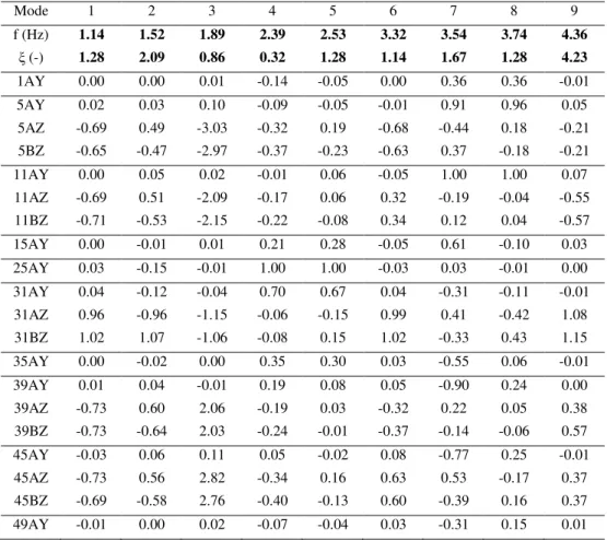
For this purpose, an 875 m long bridge, located in Central Italy, founded on piles in eluvial-colluvial soil deposit was instrumented and ambient vibration tests together with geophysical investigations were performed. Experimental modal properties were evaluated by means of operational modal analysis on accelerometric data and the role of soil-structure interaction in the interpretation of the tests was detected by means of finite element models characterised by different accuracy in addressing the interaction problem. In the soil-structure-interaction models the local site condition in correspondence with each bridge piers (determined by geotechnical and geophysical investigations) were taken into account in the definition of the soil-foundations impedances. Comparison between the experimental results obtained from ambient noise measurements on the free-field and on the viaduct deck, permits the identification of both predominant period of the site and the fundamental periods of the structure. In addition, comparisons between results obtained from the different numerical models with the measured dynamic response of the viaduct, in terms of fundamental frequencies and mode shapes, allow the identification of the contribution of different soil-structure interaction aspects such as the pile-soil-pile interaction, the radiation problem, the pile cap embedment as well as the variability of the soil stratigraphy along the longitudinal direction of the viaduct.
Referring to the transverse behaviour, some tests were performed in correspondence with one pier, measuring accelerations of the foundation cap (both translational and rotational components) and the pier bent, in order to identify the contribution to the transverse modal displacement due to the elastic deflection of the pier and the foundation rocking. The test results are compared with those obtained from a 3D finite element model of the viaduct, considering or not the soil-structure interaction problem.
In addition, other two case studies of viaducts, with different characteristics respect to the previous one, were presented, with the aim of extending the study of soil-structure interaction also for foundations with different geometrical characteristics: the first one called “Paglia bridge” is a three-spans continuous deck bridge with steel-concrete composite structure, composed by four steel beams with variable height and a r.c. slab with uniform thickness; the second one, called “Cesano bridge”, is a three-span continuous bridge with steel-concrete composite deck composed by a steel box-girder and a r.c. slab with uniform thickness.
Keywords: r.c. viaduct; Soil-Structure Interaction; dynamic identification; Operational Modal Analysis; finite element model; Foundation rocking.
Sommario
L’oggetto della tesi è lo studio dell’effetto dell'interazione terreno-fondazione-struttura e della risposta del sito sul comportamento dinamico di viadotti continui su più campate, sviluppato sia sperimentalmente tramite misurazioni di vibrazioni ambientali sia numericamente con l’ausilio di modelli raffinati agli elementi finiti.
A tal fine, si sono eseguite misure di vibrazione ambientale su un ponte multi campata di lunghezza 875 m, situato nell'Italia centrale, fondato su pali in un deposito eluviale-colluviale e per caratterizzare dinamicamente il terreno circostante si sono eseguite indagini geofisiche. Le proprietà modali sperimentali sono state valutate mediante l'analisi modale operativa su dati accelerometrici e il ruolo dell'interazione terreno-struttura nell'interpretazione dei test è stato riscontrato mediante modelli agli elementi finiti caratterizzati da diversa accuratezza nella modellazione delle fondazioni e dell’interazione con il terreno. Nei modelli di interazione terreno-struttura, è stata presa in considerazione la condizione locale del sito in corrispondenza di ciascun pilastro del ponte (derivante da indagini geotecniche e geofisiche) nella definizione delle impedenze tra fondazioni e terreno. Il confronto tra i risultati sperimentali ottenuti dalle misure di rumore ambientale sul campo libero e sull’impalcato consente di identificare sia il periodo predominante del sito che i periodi fondamentali della struttura. Inoltre, il confronto tra i risultati ottenuti dai diversi modelli numerici con la risposta dinamica misurata del viadotto, in termini di frequenze fondamentali e forme modali, consente l'identificazione del contributo di diversi aspetti di interazione tra struttura del suolo come l’interazione tra le pile, il problema della dissipazione per radiazione, l'ingombro della zattera e la variabilità della stratigrafia del suolo lungo la direzione longitudinale del viadotto.
Inoltre, con riferimento al comportamento trasversale, sono stati eseguiti alcuni test in corrispondenza di una pila del viadotto per misurare le accelerazioni del pulvino (componenti traslazionali e rotazionali) e della zattera in modo da identificare il contributo allo spostamento modale trasversale dovuto alla deformazione elastica delle pile e alla rotazione della fondazione. I risultati del test sono confrontati con quelli ottenuti dai modelli 3D del viadotto, includendo o meno il problema dell'interazione terreno struttura.
In aggiunta, vengono presentati altri due casi studio di viadotti con caratteristiche diverse al precedente, allo scopo di ampliare lo studio dell’interazione terreno-struttura anche per fondazioni con diverse caratteristiche geometriche; in particolare il ponte sul Paglia si tratta di un ponte ad impalcato continuo su tre campate avente struttura composta, con quattro travi di acciaio ad altezza variabile ed una soletta in c.a. di spessore uniforme, mentre il ponte sul Cesano si tratta di un ponte ad impalcato continuo su tre campate avente struttura composta, con travi di acciaio ‘a cassone’ ed una soletta in c.a. di spessore uniforme.
Parole chiave: Interazione terreno-struttura; identificazione dinamica degli edifici; analisi modale operativa; Modello agli elementi finiti; Rotazione della fondazione.
Introduction
The high Italian seismicity in conjunction with the existing dense transport infrastructure network require the seismic assessment and upgrading of key components of the network links (i.e. bridge, tunnels, earth-retaining system) to improve the overall earthquake resilience of communities. In this framework, system identification and structural health monitoring of structures have recently drawn attention within the civil engineering community for developing real time assessment tools and reducing uncertainties involved within the risk assessment procedure of existing structures. Estimation of the dynamic properties of structures using recorded vibration data allows the calibration of numerical models for the assessment of the structural safety and for the design of seismic retrofit. In this framework, many works are available in the literature, both for buildings (Luco JE. et al 1988, Foti D. 2014, Mirshafiei F. et al 2016, Omenzetter P. et al 2016, Ubertini F. et al 2017, Behmanesh et al 2016, Ranieri C. et al 2012) and for bridges, for which the previous considerations, especially holds since effects of non-structural components on the modal properties are very limited (Cabboi A. et al 2017, Omenzetter P. et al 2013, Cunha A. et al 2006, Zhang J. et al 2013, Zonta D. et al 2014, Polanco NR. et al 2014, Prendergast LJ. et al 2016, Chen GW. et al 2017, Li Y. et al 2017). Various testing techniques, differing for the involved equipment, time-consuming, costs, and dynamic input, can be adopted. The Ambient Vibration Test (AVT) is one of the most attractive methods for the evaluation of the dynamic properties of existing constructions in elastic range since it uses natural vibrations as input (e.g. micro tremors, wind, anthropic activities). Furthermore, small, light, and portable instrumentation is required. On the other hand, because of the low amplitude range of the ambient accelerations, the method requires the use of expensive low-noise wired accelerometers.
It is generally common practice to perform AVTs and then to calibrate finite element models by changing the mechanical properties of materials, achieving the best fit of the model results with the experimental data, especially when materials laboratory tests are not available. On the contrary, geometry of structural components is generally assumed in a deterministic way (assessed or determined through inspections) and the structure restraints at the base are assumed to be fixed. However, with reference to the latter hypothesis, it is well-known in the literature, from both numerical (Capatti MC et al 2017, Carbonari S. et al 2017, Dezi F. et al 2012, Carbonari S. et al 2011, Kappos AJ. et al 2002, Elgamal A. et al 2008, Sextos AG. et al 2003 [Part 1-2], Mylonakis G. et al 2000, Dezi F. et al 2016) and experimental studies (Safak E. 1995, Trifunac MD. et al 2001, Faraonis P. et al 2015), that Soil-Structure Interaction (SSI) may play an important role in the dynamic structural response, especially for medium or soft soil conditions and for existing bridges, which are generally characterised by foundations with relatively low dynamic stiffnesses, mainly deriving from the adoption of dated code prescriptions. In this topic, numerical models developed to interpret results of vibrational measurements should include the modelling of the soil-foundation dynamic compliance before the calibration process, essentially based on
the variation of the material mechanical properties to account for uncertainties related to the material heterogeneity and ageing effects.
The objective of this research work is to address the significance of soil-structure interaction and site response in the interpretation of vibrational tests performed on bridges. For this reason, the Chiaravalle viaduct, that is founded on piles and is connects the SS76 with the airport of Ancona (in Central Italy), is considered. Detailed experimental campaigns and surveys on both the soil deposit and the superstructure were performed to characterise the soil stratigraphy and the mechanical properties of the lithotypes, as well as the geometry of structural elements (e.g. girders, deck slab, piers, etc…) and the relevant mechanical characteristics of materials. Furthermore, AVTs were performed on both the free-field soil and the structure, to evaluate the presence of potential resonance effects between the site and structure and to identify the modal parameters of the bridge, usefull for the assessment of the finite element model to be used for the seismic upgrading design. As for the bridge, the measurement approach required acquisitions of data from more than one configuration of the sensors and the Covariance driven Stochastic Subspace Identification (SSI-Cov) approach (Magalhães F. et al 2011, Cantieni R. 2005) as well as the Post Separate Estimation Re-scaling (PoSER) technique (Dohler E. et al 2010) are adopted to perform the Operational Modal Analysis (OMA). At first, a refined 3D finite element model of the bridge is firstly developed starting from results of the experimental campaign on the superstructure and assuming the hypothesis of fixed base, obtaining fundamental frequencies and mode shapes rather different from the experimental ones. Considering the high level of knowledge of the structural geometry and the material properties, various numerical models accounting for the soil-foundation compliance are developed to improve the matching with the experimental data. The SSI is modelled according to the sub-structure approach, simulating the frequency-dependent soil-foundation impedances through Lumped Parameter Models (LPMs) (Wolf JP. 1988). In detail, the LPM developed (Carbonari S. et al 2018) in is adopted and calibrated to reproduce the dynamic impedances of soil-foundation systems obtained with models with different accuracy in accounting for the pile-soil-pile interaction, the radiation problem, the pile cap embedment as well as the variability of the soil stratigraphy along the longitudinal direction of the viaduct. Modal parameters obtained from the OMA are compared with those derived from all the finite element models of the bridge revealing the significance of SSI in the interpretation of vibrational tests performed on bridges.
For the sake of completeness, two more viaducts case studies with different geometrical characteristics are investigated, to expand the study to a larger case series. In particular, the work deals with some interesting aspects concerning the contribution of the foundation compliance on the dynamic measured response of the structure subjected to ambient vibrations. To this purpose, the Paglia bridge in Orvieto and Cesano bridge, in Corinaldo, are considered.
The present thesis work is subdivided into six chapters (in addition to the present introduction), and their contents are summarized hereinafter.
Chapter 1 describes the ambient vibration tests and their possible uses, the adopted instrumentation and the analysis methodology performed.
Chapter 2 presents the problem of soil-structure interaction (SSI) from a theoretical point of view; the formulation and the solution of the relevant dynamic problem of a superstructure, elastic-linear, supported by a rigid foundation on viscoelastic means are exposed. The direct method is presented, while the method for substructures is explained in a more rigorous way, through the study of the various problems from which it is constituted. The motion equations of the interacting system and the different solution methods are then formulated. Finally, a theoretical description of LPMs is provide.
Chapter 3 is dedicated to the general description of the viaducts. In addition to the description of all the structural elements of “Chiaravalle viaduct” (deck, stacks, abutments and foundations); the geological and geotechnical aspects of the area on which the structure is located are presented, from which the geotechnical model of the subsoil is defined; finally, a short description of “Paglia bridge” and “Cesano bridge”, useful as case studies to evaluate the contribution of the foundation rocking on transversal behaviour is presented.
Chapter 4 presents the results obtained from experimental data in terms of modal parameters with the operative modal analysis (OMA). The results are showed for all the viaducts investigated both for the overall behaviour of the deck and the behaviour of the piers.
Chapter 5 describes in detail the develop of the viaducts finite element model with different details level able to consider the soil-structure interaction problem. First of all, a fixed base model of the viaduct is presented, then how to insert an LPM in the model is shown, the different types of analysis that are carried out and the methodology of data extrapolation after a "Steady State" analysis are reported. In the final part, the conventional finite element model with springs along the piles is presented. Finally, analytical results of the foundation rocking are shown.
Chapter 1.
Ambient Vibration Tests (AVTs)
In a country with a high seismic risk such as Italy, the problems related to the design of new buildings as well as the assessment of seismic vulnerability of the built, especially with strategic importance such as hospitals, bridges and schools, constitute a research field of extreme actuality. In this sense, the knowledge of the dynamic characteristics of the construction, and therefore the methods for experimental modal analysis play a fundamental role for the calibration of the finite element models of the constructions on which to base any safety assessments, design of seismic upgrading interventions, or to correctly interpret the aspects that may cause changes in the dynamic characteristics of buildings over the time. Ambient vibration measurements are performed to evaluate modal parameters of the structures in order to develop and validate a numerical finite element models for the design of the seismic upgrading, but in the case of viaducts or bridges, these tests can be used also to evaluate the soil-structure interaction effects, through the foundation rocking of the piles in the viaducts, or a possible effect of the reduction in the depth of excavation around the piles in the bridges (Figure 1.1).
Figure 1.1 Fields of application of Ambient Vibration Tests
AVTs are performed with the aim of evaluating the modal parameters of the structure (vibration frequencies, modal shapes and damping ratios). To this purpose, piezoelectric monoaxial accelerometers PCB model 393B31 are placed at suitable configurations to capture both translational and rotational components of displacements. Sensors have been connected through coaxial cables to acquisition cards (24-bit NI 9234 acquisition cards and one chassis NI cDAQ-9178) coupled to a laptop equipped with dedicated software.
In ambient vibration tests, the input is not controlled and is assumed to have a flat spectrum such as a white noise. This assumption is not exactly true, and the input magnitude can be of a certain importance when, because of the limited number of available sensors and/or the
insufficient number of channels of the acquisition system, the structural response cannot be measured in just one test. In these cases, tests must be repeated in different times, considering different configurations (i.e. varying the sensor positions) and finally a merging operation of the recorded data is necessary. The Post Separate Estimation Re-scaling (PoSER) approach (Dohler E. et al 2010) is used to process data from non-simultaneous acquisitions; this method requires that a group of sensors, called reference sensors, are left in the same place for all the test configurations so that they can be used to scale the data of different tests, acquired by sensors moved in different places (roving sensors).
For the acquisitions, a time equal to 1000÷2000 times the period of the first mode is recommended and usually, if no more information are available, the fundamental frequency of the structure was preliminary estimated to be 1 Hz and therefore recordings with a duration of 1800 seconds (30 minutes) were made, dividing each time histories into 90 samples of 20 seconds. The analogical signal is sampled at 2048 Hz and all the frequency components in the analogic signal above the Nyquist frequency are removed through a low-pass filter to avoid aliasing.
All the recorded data were processed with standard signal processing techniques before performing the modal analyses. Initially, data were carefully inspected in order to cut those parts characterized by anomalous behaviours (signal clipping, intermittent noise, spikes and so on) due to sensor or measurement chain malfunctioning or due to signal saturation. Then, the contributions of spurious trends were eliminated through a baseline correction (adopting a second order polynomial) and the high frequency content was eliminated by filtering with a Butterworth low pass filter characterized by order 4 and a cut-off frequency of 20 Hz. Finally, signals were down-sampled at 51.2 Hz to decrease the number of data and make the successive analyses faster.
Different techniques were available to elaborate the recorder data, both in the time domain (Random Decrement, Least-Square Complex Exponential (LSCE), Ibrahim, ARMA and SSI-Cov) or in the frequency domain (Peak Picking, Averaged Normalized Power Spectral Density (ANSPD), Enhanced Frequency Domain Decomposition (EFDD) and Least-Square Complex Frequency (LSCF)).
In this thesis, the Stochastic Subspace Identification (SSI) technique (Magalhães F. 2011, Cantieni R. 2005) was used to identify the dynamic properties of the structure from the recordings.
In the case of the bridges, in addition to the tests carried out for the overall identification of the deck, experimental investigations can be performed to evaluate possible contributions of the soil-foundation compliance on the dynamic response of the bridge. For this purpose, some tests were performed in the piers with the aim of identifying the foundation translation and rocking.
Chapter 2.
Soil Structure Interaction (SSI)
Site geomorphology and interaction with the soil can significantly influence the seismic response of structures, as evidenced by post-earthquake investigations and in situ experiences (Sextos et al. 2003, Lupoi et al. 2005). The fixed-base structural models, commonly used for design, fail to capture the actual structural dynamic behaviour as they are not able to describe the deformability and dissipative capacity of the soil-foundation system. Moreover, in the case of motorway or railway viaducts, foundations of piers can be placed on non-homogeneous soils and, consequently, the seismic shaking can be variable at the different piers. In these cases, the Soil-Structure Interaction (SSI) and the non-synchronous seismic inputs must be considered in the analyses. Modern European codes such as EC8, require specific analyses to include these effects. The level of accuracy adopted to model the SSI problem may vary depending on the importance of the structure. However, even if models and analytical procedures are available, an integrated methodology is not yet available.
The procedure to include the effect of SSI in the non-linear response of bridges is based on the technique of decomposing the domain: the kinematic interaction analysis is performed in the frequency domain, with a procedure that considers radiation damping, pile-soil interaction and pile-soil-pile interaction; non-linear inertial interaction analysis, on the other hand, is performed in the time domain with the use of a finite element model of the superstructure.
To reproduce the frequency dependence behaviour of the soil-foundation system, Lumped Parameters Models (LPMs) are usually adopted and calibrated to reproduce the soil-foundation behaviour in a selected frequency range of interest. Therefore, from a structural point of view, considering the deformability of the soil-foundation system generally implies:
- a decrease of the overall stiffness of the structure;
- a modification of the seismic input to account for the actual foundation displacements (which are different for the free-field ones, especially in the case of pile foundations, and may be constituted by rotational components);
- the onset of waves that, propagating in the ground, increase the energy dissipation capabilities of the structure (radiation damping).
The general definition of the problem is therefore the evaluation of the mechanical response of a structure to a variable external excitation with time, taking into account the following aspects:
- deformability of the soil and foundation system; - dissipation of energy in the soil by geometric damping; - dissipation of energy in the soil due to its inelasticity;
2.1. SSI Direct approach
The topic of SSI can be analysed through two different approaches, the first one is known as a "direct approach", in which the structure and the soil (near field) are modelled simultaneously, together with surrounding constraints able to guarantee the radiation conditions. This approach, which usually requires high computational efforts, allows capturing the soil and structural responses simultaneously and must be used if both systems (soil and structure) behave nonlinearly. A sketch of the direct approach is reported in Figure 2.1, where surrounding constraints consisting of spring-viscous dashpot systems are used to account for the far-field compliance and damping.
Figure 2.1 Simple scheme of SSI direct approach
To describe the resolving system of an SSI direct approach, for simplicity, the overall soil-foundation-superstructure system can be divided into the following sub-systems
S E F S: Superstructure E: Embedded G ũ F: Foundation G: Ground ũ: Free-field motion
Figure 2.2 Scheme in subsystems of a soil-foundation-superstructure system
The dynamic equilibrium equations for the global system, expressed in the time domain, can be written as
0
0
0
0
0
0
0
0
0
0
( )
0
( )
S S SS SF S S E F F FS FF FF FE F E E EF EE E SS SF S S E FS FF FF FE F F EF EE E Et
t
+
+
+
+
+
=
M
u
C
C
u
M
u
C
C
C
C
u
M
u
C
C
u
K
K
u
K
K
K
K
u
f
K
K
u
f
&&
&
&&
&
&&
&
(1)where u represents the vector that groups subvectors uS, uF and uE, collecting displacements
of the nodes belonging to the superstructure, the interface and the soil, respectively; M, C and K represent the masses, damping and stiffnesses matrix, respectively and fF and fE are
vectors collecting forces deriving from the pile-soil-pile interactions as a consequence of the seismic wave propagation in the deposit.
If the soil is a viscoelastic medium, the displacements of the soil can be calculated with the relationship 0
( )
(
)
(
)
( )
( )
( )
(
)
(
)
( )
( )
t F FF FE F F E EF EE E Et
t
t
t
d
t
t
t
t
τ
τ
τ
τ
τ
τ
τ
−
−
= −
+
−
−
∫
u
h
h
f
u
u
h
h
f
u
%
%
(2)Operating in the field of validity of the overlapping principle of Boltzmann and for the principle of causality, we can note the effects of this force field as the sum of the effects induced by infinitesimal impulses applied in the generic instant τ, exploiting the convolution integral introduced in (2) to obtain the global response in terms of displacement.
This integral, takes into account the effects that an impulsive signal, generated by the effect of ũ at any point in the foundation, produces around itself by propagating through the surrounding ground. In particular, the terms of the h matrix are Green's elastodynamic functions: they describe the response of a viscoelastic system at a point different from that of the force application, taking into account the phenomena associated with the propagation of a signal in a viscoelastic medium such as internal damping of the ground and radiation damping, the damping associated with the propagation of the signal in the indefinite space.
The problem can be simplified by expressing equation (2) in the frequency domain, through the Fourier transform. By indicating with capital letters, the Fourier Transform of the relevant quantities in the time domain, the following expressions for the force vector can be obtained:
1
( )
( )
( )
( )
( )
( )
( )
( )
( )
( )
( )
( )
( )
( )
( )
( )
( )
( )
F FF FE F F E EF EE E E FF FE F F EF EE E Eω
ω
ω
ω
ω
ω
ω
ω
ω
ω
ω
ω
ω
ω
ω
ω
ω
ω
−
= −
−
=
= −
−
F
H
H
U
U
F
H
H
U
U
K
K
U
U
K
K
U
U
%
%
%
%
(3)Taking into account equation (3), system (1) can be re-written in the frequency domain as follows: 2 2 2
0
( )
( )
0
( )
0
0
0
0
0
0
( )
( )
( )
( )
0
( )
( )
( )
SS SS SS SF SF S S E S E FS FS FF FF FF FE FE F EF EF EE EE EE E G G FF FE F F G G EF EE Ei
i
i
i
i
i
i
ω
ω
ω
ω
ω
ω
ω
ω
ω
ω
ω
ω
ω
ω
ω
ω
ω
ω
ω
ω
+ +
−
+
+
+
−
+
+
=
+
−
+
=
=
K
M
C
K
C
U
K
C
K
M
C
K
C
U
K
C
K
M
C
U
K
K
U
F
K
K
U
%
%
%
E( )
ω
F
%
(4)Collecting the vector of displacements and introducing the matrix of impedances Z, equation (4) can be rewritten in the compact form
0
( )
0
( )
( )
0
( )
( )
SS SF S S EG FS FF FF FE F F EF EE E Eω
ω
ω
ω
ω
+
=
Z
Z
U
Z
Z
Z
Z
U
F
Z
Z
U
F
%
%
(5)System (5) represents the solving system according to the SSI direct approach. It is evident that the problem solution is very complex, since all the subsystems in which we have divided the problem are coupled.
2.2. SSI Substructure approach
The second approach is known as "substructures approach" and is consists in a technique where the SSI problem is solved by decomposing the whole soil-foundation-superstructure system into two subsystems (the soil-foundation system and the structural system). The response of the soil-foundation system subjected to the seismic excitation is firstly determined, obtaining the system compliance and the foundation input motion; then the structural response on compliant restraints subjected to the foundation motion is evaluated. The approach allows adopting specific analysis methodologies and tools to study the soil-foundation system (kinematic interaction analysis and impedances determination) and the superstructure system (inertial interaction analysis). The substructure approach is based on the superposition principle, valid for linear systems but can be also adopted to include structural nonlinearities.
1. solution of the kinematic interaction problem. This step allows capturing the soil-foundation interactions and leads to the evaluation of the soil-foundation input motion (FIM), namely the motion experienced by the foundation subjected to the seismic wave field. Due to the soil-foundation system linearity the problem is solved in the frequency domain in order to easily account for the frequency-dependent behaviour of the system.
2. Evaluation of the soil-foundation system dynamic stiffness. This step leads to the evaluation of the frequency-dependent dynamic impedance matrix of the soil-foundation system, detached from the superstructure. The real part of the impedance matrix, reflects the compliance of the soil-foundation system and it may be represented by a spring with a frequency-dependent coefficient, while the imaginary part captures the energy dissipation occurring in the soil as the foundation vibrates (mainly due to the radiation damping).
3. Calculation of the dynamic response of the structural system subjected to the FIM. Inertial interaction is taken into account in this step. In order to evaluate inertial effects in the soil-foundation system, the inertial contribution to the foundation motion, which may be determined at this step by subtracting the FIM to the inertial foundation displacement, needs to be evaluated and applied to the soil-foundation system at the foundation level. The global soil-foundation response is finally determined superimposing the latter results to those determined in step 1.
The inertial interaction analysis can be performed either through time and frequency domain analyses. Frequency-domain analyses are carried out by implementing the frequency-dependent dynamic impedance matrix previously computed in the finite element model (FEM) of the superstructure, at the foundation level. This generally presents difficulties since commercial structural analysis programs does not include library elements able to introduce fully coupled frequency-dependent matrices. In time-domain analyses, otherwise, it is possible to account for the linear or non-linear behaviour of the superstructure. However, the frequency dependent impedance matrix of the soil-foundation system cannot be used and an implementation strategy must be adopted. Generally, dynamic Lumped Parameter Models (LPMs) having frequency independent parameters are used; parameters are calibrated so that the dynamic impedance of the LPM approximates the soil-foundation one in the frequency range of interest. Figure 2.3 reports a scheme of the "sub-structures approach".
Figure 2.3 Simple scheme of SSI substructures approach
time-domain
FIMs
free field ground motion frequency-domain
=
FIMs
impedances
or frequency-domain
The substructure approach (applicable under the hypothesis of validity of the overlapping effects principle) allows to solve this system of equations by decoupling the soil-foundation system from that of the superstructure and solving two different systems of equations separately. The first phase is called kinematic interaction and analyses the substructure consisting of E and G (Figure 2.4)
E E: Embedded G ũ G: Ground ũ: Free-field motion F: Foundation F
Figure 2.4 Scheme in subsystems EG in SSI substructure approach
The solving system of this substructure makes it possible to derive the displacements to which the underground foundation is subjected due to the effect of the seismic input, in the absence of superstructure, the motion at the base of the structure (at interface F) and the dynamic impedance of the foundation soil system. This system is:
, , EG F K FF FE F E K EF EE E
=
U
Z
Z
F
U
Z
Z
F
%
%
(6)where UF,Kand UE,K are the “kinematic” displacements. Evaluating UE,K from the second
equation of (6) and replacing it in the first equation of (6), the following expression is obtained:
(
)
1(
)
1 , EG EG EG EG EG EG FF FE EE EF F K F FE EE E − −
−
=
−
Z
Z
Z
Z
U
F
%
Z
Z
F
%
(7)If we indicate with
ℑ =
Z
EGFF−
Z
EGFE(
Z
FEEG)
−1Z
EFEG the impedance of soil-structure system, the displacements UF,KandUE,K can be determined as follow(
)
1 1 , EG EG F K FIM F FE EE E − −
=
= ℑ
−
U
U
F
%
Z
Z
F
%
(8)(
)
1{
1(
)
1}
, EG EG EG EG E K EE E EF F FE EE E − −
−
=
−
ℑ
−
U
Z
F
%
Z
F
%
Z
Z
F
%
(9)S
: Impedance
FIM: Foundation Input Motion S: Sovrastructure
FIM
Figure 2.5 Scheme in subsystems S in SSI substructure approach
Taking into account equations (7) and (8), UE can be obtained from the third equation of
(5). It results
(
EG)
1(
EG)
E EE E EF F −=
−
U
Z
F
%
Z
U
(10)From the second equation of (5), it can be obtained:
(
S)
FS S
+
FF+ ℑ
F= ℑ
FIMZ U
Z
U
U
(11)So, the solving system of inertial interaction for the superstructure, is represented in the following form:
0
SS SF S S FS FF F FIM
=
+ ℑ
ℑ ⋅
Z
Z
U
Z
Z
U
U
(12)The system (12), in which the results of the kinematic interaction were highlighted (the influence of the foundation and of the soil on the superstructure), provides displacements and stresses on the superstructure. Determined UF, is also possible to determine the movements
of the underground foundation from (10). The difference between the latter and those obtained from the kinematic interaction phase are the so-called inertial displacements of the foundation.
2.3. Lumped parameter model for time-domain analysis
The analysis of the soil-foundation system allows evaluating the soil-foundation dynamic impedances, namely the complex-valued forces-displacements relationships which define the compliant restraints of the superstructure in the subsequent inertial interaction analysis. Different models have been developed over the years to this purpose, however, since foundation impedances are frequency-dependent functions, all procedures furnish results that may be adopted directly only if the inertial interaction analysis of the superstructure is performed in the frequency-domain.
Dezi et al. (2009), recently proposed a numerical model for the analysis of the 3D kinematic interaction of the groups of piles on horizontal-layer plots, based on the BEM-FEM pair where the piles are modelled with beam elements while the ground is schematised with horizontal, independent and infinite layers. The dynamics of the ground layer is described by means of the Green functions, which allow to consider both the pile-soil-pile interactions and the irradiation damping. These derive from a simplification of the Novak plan model, (1978) also developed by Gazetas and Dobry, (1984). The model allows to evaluate all the components of the impedance-dependent matrix of the foundation (eg translational, rotational and roto-translational impedances).
Foundation impedances are frequency-dependent functions, all previous procedures provide results that can be directly adopted in an analysis of the superstructure interaction in the frequency domain (inertial interactions). However, this type of analysis can only be used if the superstructure behaves linearly, moreover it is a typology of analysis less know to professional engineers than to the analysis in the time domain. If the analysis of the inertial interaction are developed in the time domain, as in the case of non-linear behaviour of the structure, the Lumped Parameter Model (LPM) must be introduced, obtained by assembling springs, masses and dampers to reproduce the behaviour dynamic of the foundation.
x
y
z
Figure 2.6 Soil-foundation system
A generic set of vertical piles placed in a stratified soil and connected at the head by a rigid cap is considered (Figure 2.6). The group of n piles of length L is modelled with elastic Euler-Bernoulli beam elements embedded in a medium constituted by independent horizontal viscoelastic infinite layers. Under the assumption that no gaps arise between piles and soil during the motion, the problem is linear, and the dynamic equilibrium condition of the system can be derived from the Lagrange-D’Alembert principle. By approximating the displacement field within the piles, according to the finite element approach, the following complex valued system of coupled linear algebraic equations can be obtained
( )
( )
( )
2
P
ω
P Pω
ω
ω
−
+
=
where KP, MP and ZP(ω) are the stiffness and mass matrices of the piles and the impedance
matrix of the soil, respectively, obtained by assembling the contributions of the elements,
U(ω) is the vector grouping the pile nodal displacements and f(ω) is the vector of the external nodal forces due to the free-field motion.
The cap that connects the pile heads is considered by introducing a rigid body constraint characterised by the geometric matrix A that permits to express the nodal displacement vector as a linear function of the 6 displacements of the rigid body master node F (UF) and the
displacements of the sections of the piles embedded in the layered media (UE),
F E
=
U
U A
U
(14)Taking (14) into account, (13) transforms into
FF FE F F EF EE E E
=
Z
Z
U
f
Z
Z
U
f
(15) Where(
2)
FF FE T P P P EF EEω
=
−
+
Z
Z
A
K
M
Z
A
Z
Z
F T P E
=
f
A f
f
(16)System (16) can be thus condensed as
( )
1 F F FE EE Eω
−ℑ
d
=
f
−
Z Z f
(17) Where( )
(
1)
FF FE EE EFω
−ℑ
=
Z
−
Z Z
Z
(18)is the 6x6 impedance matrix of the soil-foundation system that expresses forces to be applied at F in order to produce unit steady uncoupled vibrations of the node F itself. This matrix is complex-valued and is generically fully populated depending on the piles layout and the position of the reference node; however, in the case of doubly symmetric system, by locating the reference node F at the intersection of the two symmetry axes, the impedance matrix has the form
( )
ℑ
ℑ
ℑ
ℑ
ℑ
ℑ
ℑ
ℑ
=
ω
ℑ
− − rz ry rx z rx y y ry x xsym
0
0
0
0
0
0
0
0
0
0
0
0
0
(19)If time-domain inertial interaction analyses are performed, as in this case, suitable Lumped Parameter Models (LPMs) must be introduced to reproduce the foundation dynamic behaviour. LPMs are constituted by frequency-independent springs, dashpots and masses, suitably assembled and calibrated in order to reproduce the dynamic behaviour of the soil-foundation system. The numerical model of Dezi et al. (2009), in which piles are modelled with beam elements and the soil is schematized with independent horizontal infinite layers, is used for the definition of the foundation impedances, while the LPM parameters are determined in accordance to the model proposed by Carbonari et al. (2012).
c
zm
zk
rzI
z Vertical & torsionalk
zc
rz Planeyz
Plane xzk
yc
ym
yI
x Plane yzh
kyh
cyh
myk
yhc
yhm
yhm
xI
ym
xhk
ryc
ryk
xc
xk
xh Plane xzc
xhh
kxh
cxh
mx Master nodey
x
z
F
Figure 2.7 Scheme of the adopted LPM
In this thesis the LPM presented by Carbonari et al. (2012) is adopted to simulate the soil-foundation dynamic behaviour of each pier in the CB models (Figure 2.7). Each LPM is characterized by 24 parameters, namely the translational (mx, my and mz) and rotational masses (Ix, Iy and Iz), lumped at the external node of the LPM, the elastic (kx, ky, krx, kry, kz and krz) and viscous (cx, cy, crx, cry, cz and crz) constants that define the relevant spring-dashpot elements and two additional eccentric masses (mxh, myh) connected to the external node by stiff links (of lengths hx and hy) and to the ground by spring-dashpot elements (kxh, kyh, cxh, cyh). The adopted LPM is capable to reproduce the frequency dependent dynamic impedance
![Figure 4.9 represents the first three mode shapes of KC2 1 0 -1 1 0 -1 1 0 -1 x [m] 385 412.5 440 467.5 495 522.5 550 557.5 605 632.5357.5OMA](https://thumb-eu.123doks.com/thumbv2/123dokorg/2968169.27086/48.892.193.659.219.500/figure-represents-mode-shapes-kc-x-m-oma.webp)