UNIVERSITY
OF TRENTO
DEPARTMENT OF INFORMATION AND COMMUNICATION TECHNOLOGY
38050 Povo – Trento (Italy), Via Sommarive 14 http://www.dit.unitn.it
D
ESIGN OF ANI
NTEGRATEDA
NTENNA FORA
UTOMOTIVES
YSTEMSR. Azaro, G. Boato, F. De Natale, G. Franceschini, A. Martini and
A.Massa
May 2005
Design of an Integrated Antenna for
Automotive Systems
R. Azaro, G. Boato, F. De Natale, G. Franceschini, A. Martini and A. Massa Department of Information and Communication Technology
University of Trento, Via Sommarive 14, 38050 Trento, ITALY E-mail: [email protected]
Abstract - This paper describes the design process of an integrated antenna for an automotive rescue system. In order to fulfill the antenna design requirements in different frequency bands and to minimize the interference phenomena arising from the integration of different classes of antennas in a single device, a two-phases stochastic optimization approach is used. The experimental validation carried out on the developed prototype confirms the effectiveness of the proposed approach.
Introduction
An automotive rescue system able to fully exploit available wireless services such as timing, localization, and data exchange (e.g., SARSAT, GSM/GPRS and GPS) requires an antenna system operating in different frequency bands. Due to the automotive application constraints, important issues arise concerned with the coexistence of more antennas in a limited space as well as limited weight and volume. This paper describes the antenna system developed within the AIDER (Accident Information and Driver Emergency Rescue) project aimed at developing an accident management system able to optimize time and effectiveness of rescue operators. The design of an antenna for each wireless subsystem (COSPAS-SARSAT, GPS, GSM/GPRS)
is not critical in itself, while the design of an integrated antenna requires a great care to avoid mutual coupling effects arising when the radiating subsystems have to be placed in a single limited volume. Starting from the electrical guidelines of the rescue system and taking into account the geometrical constraints, the antenna design has been optimized through a two-phases strategy, as described in the following section. A prototype of the device has been built and validated through a set of experimental tests.
Antenna design and results
The design of the multifunction antenna was carried out by means of a two-phase process. The first two-phase is aimed at defining the more appropriate class of antennas for each wireless service by taking into account physical as well as electric constraints. As far as the COSPAS-SARSAT and the GSM/GPRS systems are concerned, a monopole antenna turns out to be a good choice. Since the GSM/GPRS system operates in two different frequency bands, a dual-band monopole is adopted by considering a LC tuning device allowing the multi-band operations. A more demanding task is related to the selection of a proper antenna subsystem for the GPS function. In fact, it is necessary to handle the effects of multi-path phenomena caused by reflections and to achieve a hemispherical coverage to receive signals from a large number of satellites. A good solution is represented by a right-hand polarized antenna with a good cross-polarization-rejection-ratio able to discriminate between direct and reflected signals. Since patch antennas are narrow-band devices and the resonant frequency varies depending on the ground plane size as well as on the dielectric loading [1], a conical version of
the so-called two-arm Archimedean spiral antenna was chosen. Spiral structures are relatively insensitive to mutual coupling phenomena [2] [3] and they present a wide hemispherical lobe as well as good cross-polarization-rejection-ratios [4].
The second phase deals with the integration of antenna subsystems (defined in the previous phase) to find their optimal physical parameters and placement as well as to solve interference problems. After the definition of the gain G
(
θ,ϕ,f)
and of the Voltage Standing Wave Ratio VSWR( )
f of the integrated multifunction antenna, and of the related requirements Gmin(
θ,ϕ,f)
and VSWRmax( )
f , f being the working frequency, θ and ϕ the angular coordinates, the following cost function is maximized( )
(
(
)
(
)
)
( )
( )
( )
∑
∑∑∑
− = − = − = − = ∆ ∆ − ∆ + ∆ ∆ ∆ ∆ ∆ ∆ − ∆ ∆ ∆ = Θ 1 0 max max 1 0 1 0 1 0 min min , 0 max , , , , , , , 0 max F i F i V v T t f i VSWR f i VSWR f i VSWR f i v t G f i v t G f i v t G ϕ θ ϕ θ ϕ θ κ (1) where κ ={
xa(0),ya(0),za(0) =0.0,γa;∀a∈(
SRS,GSM/GPRS,GPS)
}
, and(
(0), (0), (0) =0.0)
a a a y zx is the location of the a-th radiating subsystem on the ground
plane. The unknown array
a
γ defines the physical characteristics for each antenna sub-system. More in detail, γSRS =
{
lSRS,dSRS}
for the SARSAT monopole, γGSM ={
lGSM(1) ,lGSM(2) ,dGSM,L,C}
for the double band GSM/GPRSmonopole, and
{
GPS GPS GPS GPS GPS GPS}
GPS r ,r ,h ,h ,S ,d ) 2 ( ) 1 ( ) 2 ( ) 1 ( =γ for the GPS spiral antenna.
lumped components of the tuning circuit for the dual-band, ( (1) GPS r , (1) GPS h ) and ( (2) , (2) GPS GPS h
r ) the radius and the position of the lower (1) and of the upper (2) spiral turn of the GPS helix antenna, and SGPS the distance between two adjacent turns of the helix antenna.
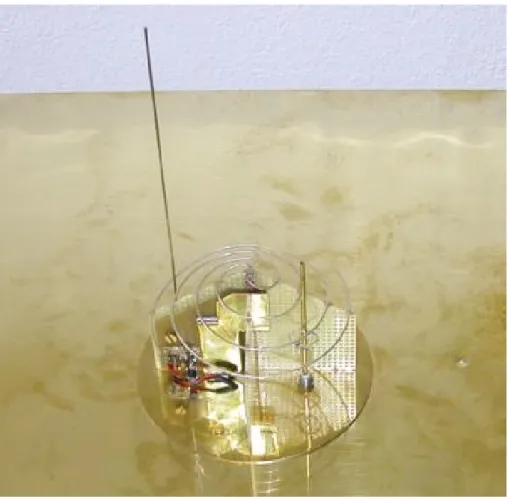
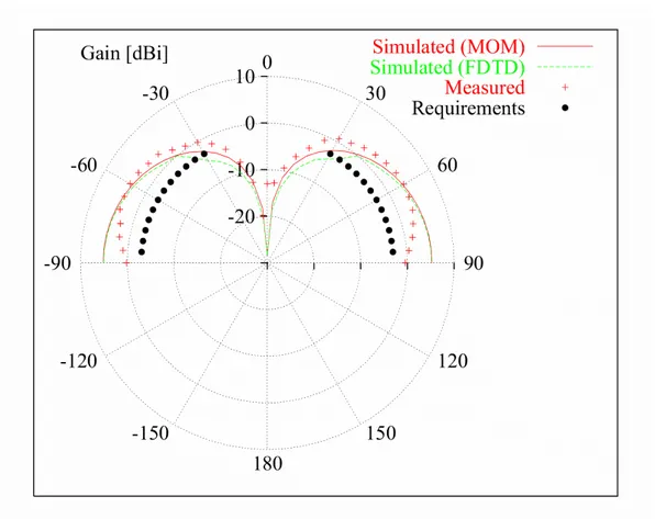
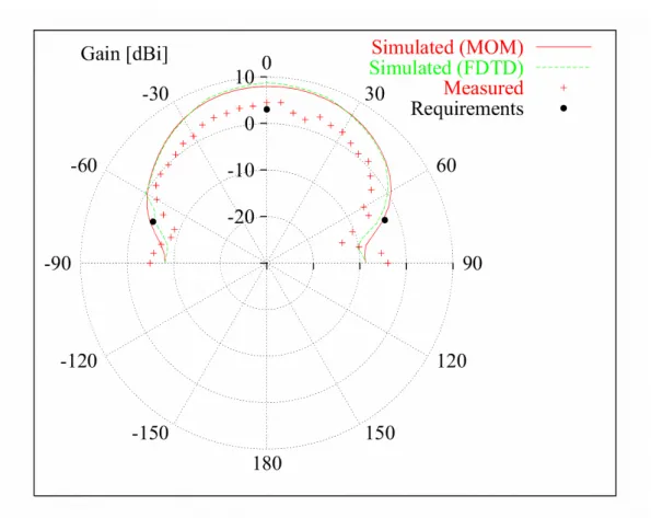
Figure 1 shows a photograph of the synthesized multifunction antenna as obtained at the end of the optimization process performed with a PSO-based approach [5] [6] according to the constraints detailed in Table 1. The maximum vertical dimension of the integrated antenna is due to the SARSAT monopole (lSRS =175mm), while the remaining part of the antenna is characterized by a maximum height of about 65mm and the diameter of wires is equal to dSRS =dGSM =dGPS =1mm. Figure 2 shows the behavior of the simulated and the measured gain function for the COSPAS-SARSAT band along a vertical plane. The measured gain values are always more than 3dB over the specifications. The simulated values have been obtained by means of a MoM-based and of an FDTD-based code.
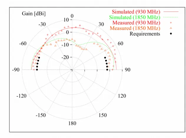
The same comparison is given for GSM/GPRS bands (Fig. 3). As requested, the gain of the synthesized antenna complies with the specifications near the central frequencies (930 MHz and 1.85 GHz). Furthermore, Fig. 4 shows measured and simulated gain values along a vertical plane for the GPS frequency band. The measured values satisfie the project constraints at
o
0 =
θ , while the antenna gain turns out to be of about 6dB under the required threshold at o
70 ± =
θ . Such a result can be considered acceptable since a pre-amplification of about 28dB is required, as well. To further assess the reliability of the integrated antenna, the polarization state of the
prototype in the GPS band has been evaluated. Similar results as those shown in Fig. 4 were also obtained in the orthogonal vertical plane, thus indicating the presence of a circular polarization. For the sake of completeness, Tab. 1 provides the measured VSWR values as well as the project requirements.
Conclusions
The design of an automotive multi-function antenna has been described. The results of the experimental and numerical validation have been reported to confirm the compliance with the specifications as well as the effectiveness of the design procedure.
Acknowledgments
This work has been partially supported in Italy by the "WILMA - Wireless Internet and Location Management Architecture" - Fondo Progetti 2002, Istituto Trentino di Cultura.
References
1 N. Padros, J. I. Ortigosa, J. Baker, M. F. Iskander, “Comparative study of high-performance GPS receiving antenna designs,” IEEE Trans. Antennas Propagat., vol. 45, pp. 698-706, Apr. 1997.
2 J. D. Kraus, Antennas. McGraw-Hill, New York, 1988.
3 C. A. Balanis, Antenna Theory: Analysis and Design. Wiley, New York, 1996.
4 D. M. Sazonov, Microwave Circuits and Antennas. Mir Publisher, Moscow, 1998.
5 A. Massa and M. Donelli, “A computational approach based on a particle swarm optimizer for microwave imaging of two-dimensional dielectric scatterers,” IEEE Trans. Microwave Theory Tech., in press. 6 J. R. Robinson and Y. Rahmat-Samii, “Particle swarm optimization in
electromagnetics,” IEEE Trans. Antennas Propagat., vol 52, pp. 771-778, Mar. 2004.
Tables captions:
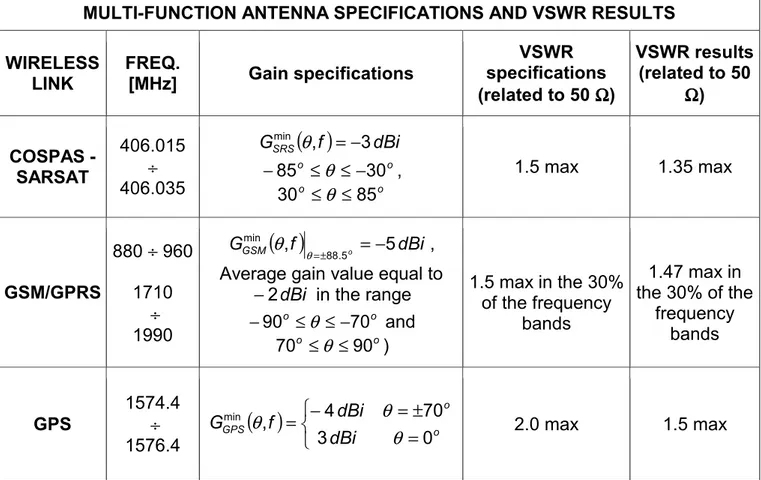
Table 1 Multi-function antenna specifications and VSWR results
Figure captions:
Fig. 1 A photograph of a prototype of the multifunction antenna Fig. 2 Multi-function antenna gain for COSPAS-SARSAT band ____________ Simulated (MOM)
--- Simulated (FDTD) +++++++++++ Measured
•••••••••••••• Requirements
Fig. 3 Multi-function antenna gain for GSM/GPRS bands ____________ Simulated (930 MHz)
--- Simulated (1850 MHz) +++++++++++ Measured (930 MHz) ∆∆∆∆∆∆∆∆∆∆∆∆ Measured (1850 MHz) •••••••••••••• Requirements
Fig. 4 Multi-function antenna gain for GPS band ____________ Simulated (MOM)
--- Simulated (FDTD) +++++++++++ Measured
MULTI-FUNCTION ANTENNA SPECIFICATIONS AND VSWR RESULTS WIRELESS LINK FREQ. [MHz] Gain specifications VSWR specifications (related to 50 ΩΩ) ΩΩ VSWR results (related to 50 Ω Ω Ω Ω) COSPAS - SARSAT 406.015 ÷ 406.035
( )
f dBi GSRSmin , 3 − = θ o o 30 85 ≤ ≤− − θ , o o 85 30 ≤θ ≤ 1.5 max 1.35 max GSM/GPRS 880 ÷ 960 1710 ÷ 1990( )
f dBi GGSM , 88.5o 5 min − = ± = θ θ ,Average gain value equal to dBi 2 − in the range o o 70 90 ≤ ≤ − − θ and o o 90 70 ≤θ ≤ ) 1.5 max in the 30% of the frequency bands 1.47 max in the 30% of the frequency bands GPS 1574.4 ÷ 1576.4