Optical Wireless Communications:
new opportunities and applications
Phd Course in Emerging Digital Technologies
Academic Year
2017/2018
Optical Wireless Communications:
new opportunities and applications
Author
Alessandro Sturniolo
Supervisor
Ernesto Ciaramella
Tutor
Giulio Cossu
Contents
Contents i
Acronyms v
Abstract ix
Acknoledgements xi
1 New frontiers of communications 1
1.1 Limits and issues of radio systems . . . 2
1.2 New opportunities and applications . . . 6
2 Optical Wireless Communication Systems 9 2.1 System configurations . . . 10
2.2 Transmitting devices . . . 12
2.2.1 Electrical characteristics of diodes . . . 12
2.2.2 Light Emitting Diodes . . . 14
2.3 Receiving devices . . . 17
2.3.1 Positive-Intrinsic-Negative diodes . . . 17
2.3.2 Avalanche Photodiodes . . . 17
2.3.3 Camera Image Sensors . . . 18
2.4 Channel properties . . . 19
2.4.1 Optical channel model . . . 19
2.4.2 Optical noise sources . . . 22
2.5 Modulation formats . . . 24
2.5.1 Non-Return to Zero . . . 25
2.5.2 DC-balanced modulations . . . 26 i
3 Embedded VLC indoor transmission system 29
3.1 State of the art . . . 29
3.2 System setup . . . 31
3.3 System characterization . . . 33
3.4 Impact of background light on BER . . . 35
3.5 Ethernet transmission . . . 39
4 Optical Camera Communications 43 4.1 State of the art . . . 43
4.2 Background theory . . . 45
4.2.1 Rolling shutter mechanism . . . 45
4.2.2 Pin-hole camera model . . . 47
4.3 Experimental setup . . . 48
4.4 Characterization . . . 50
4.5 RoI-detection algorithm . . . 51
4.5.1 Intensity-based detection . . . 51
4.5.2 Intensity and shape detection . . . 53
4.6 Applications of the detected RoI . . . 56
4.6.1 RoI-based signal normalization . . . 56
4.6.2 Packet repetition schemes for distance-related infor-mation loss . . . 59
5 Underwater Optical Wireless Communications 63 5.1 State of the art . . . 63
5.2 Underwater channel characteristics . . . 65
5.2.1 Water attenuation . . . 65
5.2.2 Sunlight background . . . 68
5.3 Optical modems design . . . 68
5.3.1 Optical Communication part . . . 69
5.3.2 Electronic layer . . . 72
5.3.3 Watertight containers . . . 74
5.4 Laboratory tests . . . 75
5.4.1 Experimental setup . . . 75
5.4.2 Analysis of the background light impact . . . 76
5.5 Field test . . . 79
5.5.1 Environmental conditions . . . 79
5.5.2 Experimental setup . . . 81
5.5.3 Fixed modems test . . . 83
5.5.4 Mobile transmission test . . . 85
CONTENTS iii
6 Conclusions 89
Acronyms
AC Alternating Current
ADC Analog-to-Digital Converter APD Avalanche Photodiode AR Augmented Reality
ARM/FPGA FPGA-based Application Real-time Microcontroller board ASK Amplitude Shift Keying
AUV Autonomous Underwater Vehicle AWGN Additive Gaussian White Noise BER Bit Error Ratio
BG Background
BJPR Beacon Jointed Packet Reconstruction CCD Charge-Coupled Device
CCT Correlated Color Temperature CDR Clock and Data Recovery CDS Correlated Double Sampler CIS Camera Image Sensor
CMOS Complementary Metal Oxide Semiconductor CSK Color Shift Keying
DC Direct Current
DD Displacement Damage DFB Distributed FeedBack D-LOS Directed Line-of-Sight DMT Discrete Multi-Tone
D-NLOS Directed Non-Line-of-Sight DSP Digital Signal Processing E.M. electromagnetic
EMI Electro-Magnetic Interference FFT Fast Fourier Transform FOV Field-of-View
FPGA Field-Programmable Gate Array FTU Formazin Turbidity Unit
fps frames per second GaN Gallium Nitride GS Global Shutter
HEP High-Energy Physics HetNet Heterogeneous Networks HT-DLOS High Tolerance DLOS
IM/DD Intensity Modulation with Direct Detection IoT Internet of Things
IPS Indoor Positioning System IR Infrared
vii LAN Local Area Network
LASER Light Amplification by Stimulated Emission of Radiation LD Laser Diode
LED Light Emitting Diode
LOON Littoral Ocean Observatory Network LOS Line-of-Sight
MIMO Multiple Input Multiple Output mm-wave Millimeter-Wave
MOS Metal Oxide Semiconductors ND-LOS Non-Directed Line-of-Sight ND-NLOS Non-Directed Non-Line-of-Sight NRZ Non-Return to Zero
OCC Optical Camera Communication OLED Organic Light Emitting Diode OOK On-Off Keying
OSNR Optical Signal-to-Noise Ratio OWC Optical Wireless Communication PAN Personal Area Network
Ph-LED Phosphor LED PIN Positive-Intrinsic-Negative PD photodiode
PRBS Pseudo Random Bit Sequence PSD Power Spectral Density
RMS Root-Mean-Square RoI Region of Interest
ROV Remotely Operated Vehicle RS Rolling Shutter
RX receiver RZ Return to Zero
SDCS Software Defined Communication Stack SNR Signal-to-Noise Ratio
TIA Trans-Impedance Amplifier TX transmitter
UAV Unmanned Autonomous Vehicle
UOWC Underwater Optical Wireless Communication UWSN Underwater Wireless Sensor Network
VCSEL Vertical Cavity Surface Emitting LASER VLC Visible Light Communication
VLCA Visible Light Communication Association VLCC Visible Light Communications Consortium VPN Virtual Private Network
WDM Wavelength Division Multiplexing YAG Yttrium Aluminum Garnet
Abstract
Optical Wireless Communications (OWCs) are a family of technologies for wireless communications which exploit optical signals for data transmission. More generally the term OWC is used to describe an optical communication in the near-Infrared (IR) portion of the electromagnetic spectrum, while transmissions in the visible range (380 − 780 nm) are usually referred to as Visible Light Communications (VLCs).
The first papers about OWC can be traced back to the ’70s [1], and to 2001 for VLC. InfraRed Data Association (IrDA), founded in 1993, pro-vided the standardization for IR communications to push the commercial development of this technology. On the other side, it was necessary to wait until 2003 for visible technology to become subject of interest outside the academic world with the founding of the Visible Light Communications Consortium (VLCC) in Japan , that in 2014 became Visible Light Commu-nication Association (VLCA) [2]. Although a vast segment of these writings is represented by telecommunications, there are relevant contributions, new concepts and ideas, that branched to address novel applications and fea-tures.
Moreover, the evolution of the Internet of Things (IoT) and of the ”always connected” paradigm has highlighted the limitations of widespread wireless radio systems. Interference, strictly regulated bandwidth and environmental constrains represent obstacles that affect Radio Frequency (RF) signals and hence limit the development of RF-based applications.
Among these, secure Personal Area Network (PAN), underwater communi-cations for autonomous vehicles or transmission systems for high radiation environments represent a range of applications that can be addressed by OWC technology.
This thesis addresses the study and the design of OWC and VLC systems as an alternative to RF communications, in particular whenever RF are not suitable for specific applications. The thesis is organized as follows:
Chapter 1 details the known limits and issues of RF systems and a brief ix
description of the OWC and VLC alternatives already explored for selected applications.
Chapter 2 presents a general description of OWC communications, describ-ing their general features, adopted devices, channel properties and modula-tion formats.
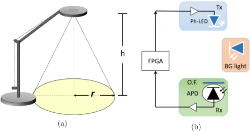
Chapter 3 describes the design and testing of a VLC prototype embedded in a common table lamp for indoor PAN with an extended characterization of its performances.
Chapter 4 reports the design and testing of a Optical Camera Communi-cation (OCC) system with a novel approach to the use of Region of Inter-est (RoI) algorithms to improve signal processing and reduce channel losses. Chapter 5 relates to the design, realization and testing of a pair of under-water optical modems that provide Ethernet connection in harsh conditions in an operative scenario.
Chapter 6 finally summarizes the contributions presented in the previous chapters and gives a picture of the future possible developments of the ap-plications explored in this thesis.
Acknoledgements
I would like to express my gratitude to professor Ernesto Ciaramella for his guidance and help along this three years that shaped me on a human and professional level.
I must highlight here that all the achievements of this thesis would not have been possible without Dr. Giulio Cossu. He mentored me in this journey and never refused to spend an helping word, whichever the situation. During my PhD I had the privilege to be hosted as visiting researcher at Northumbria University in Newcastle upon Tyne, UK. It was an incredible opportunity to be there and an absolute pleasure. I shared ideas and beau-tiful moments with professor Zabih Ghassemlooy and all the colleagues and friends of Newcastle: Navid, Andrew, Khald, Osama and Hubert.
Thanks to all the friends that I found here in Pisa and built my new life outside of my hometown: thanks to Mario, Antonella, Stella, Silvia e Fabio. To the friends that chose to come here from my hometown to follow my same path, helping me with my ”Romesickness”: thanks to Alessandro, Lorenzo and Federico.
I owe deep gratitude to my Buddhist community and my mentor Daisaku Ikeda for their constant support and encouragement.
I would like to state all my gratefulness for my family: my father, my mother and my grandmother. Although it required a fair share of hard work and effort to reach this point, I must admit that it was easy to touch the clouds by standing on the shoulders of giants.
Finally my greatest thanks goes to Sara, the person that have shared my everyday wins and losses, my happiness and my deep sorrows. Thanks for being with me and to be yourself and nothing less in every single day of our life together.
I love you.
Chapter 1
New frontiers of
communications
New technology trends and the sustained growth of mobile communications are stretching the limits of the widely adopted Radio Frequency (RF) wire-less technology. People working in Optical Wirewire-less Communication (OWC) explored since the ’70s the use of optical signals as an alternative [1]. A typ-ical OWC uses an opttyp-ical source, like a Light Emitting Diode (LED) or a Light Amplification by Stimulated Emission of Radiation (LASER) de-vice, as transmitter. By modulating the emitted optical power and using a photodetector to translate the optical signal into the electrical domain is possible to convey an information at a certain distance.
The development of high brightness and efficient visible LEDs for lighting infrastructures represents one of the main factors that allowed the creation of Visible Light Communication (VLC).
Nowaday, lighting accounts for up to 15% of the global electricity consump-tion and up to 5% of world greenhouse emissions [3]. Common LED lamps today use 85% less energy than incandescence-based lightbulbs and their diffusion has already showed a positive impact on energy consumption that will grow in future. Moreover, following the improvements in manufactur-ing and devices’ electronics, LED cost has substantially dropped in the last years [4].
Compared to traditional lighting devices (incandescence lightbulbs, fluores-cent tubes, halogen lamps etc.), LED lamps can benefit from a wider mod-ulation band due to a faster response to electric current variations. This feature can be exploited to deploy new services by means of lighting infras-tructures as novel medium for data network, achieving bit rates higher than
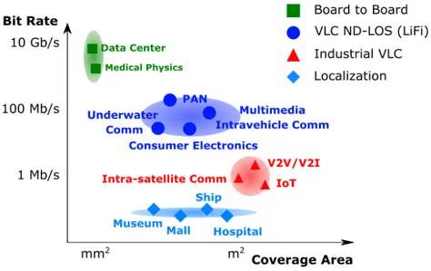
Figure 1.1: The different characteristics and performance of the novel OWC and VLC systems are paving the road for new wireless scenarios.
Wi-Fi systems (see Fig. 1.1).
1.1
Limits and issues of radio systems
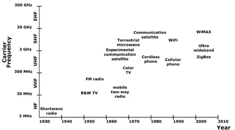
In the last century, wireless radio communications, which are now perva-sive, changed the life of citizens by various technological implementations, such as radio, TV, satellite, cellular, Bluetooth and Wi-Fi, as summarized in Fig. 1.2.
RF waves have strong potential in wireless communications: thanks to diffraction, the corresponding signals can cover wide areas and are robust to shadowing. However, the same physical features of RF wireless communica-tions that represent a unique advantage prevent their use in various wireless applications:
• are prone to interference phenomena limiting their use in sensible ap-plication scenarios (e.g. hospitals, high-security environments) or to jamming by external attackers;
electro-1.1. LIMITS AND ISSUES OF RADIO SYSTEMS 3
Figure 1.2: RF wireless applications presented with their frequency band and developing year
magnetic fields;
• due to strong attenuation in water are limited to very short transmis-sion distances (<< 1 m);
• long propagation radius, multipath and fading effects limit the density of wireless nodes that can be deployed and hence limit the user density. • propagation distance and robustness to shadowing also imply an easy access to transmitted information, that can be intercepted by un-wanted eavesdroppers.
• as the maximum bit rate achievable is a function of the maximum frequency available, reaching very high bit rate (e.g. 10 Gbit/s) is very hard using RF signals; these issues are partially accounted when higher carrier frequency is considered (e.g. 60 GHz), but this means approaching the domain of conventional optics, i.e. moving to the region where diffraction effects become lower and lower.
The issues related to the scarcity of resources available have their roots in the limits and rules that govern the RF spectrum allocation. The entire RF spectrum spans a range of approximately 300 GHz, with most part of it being licensed or subject to limitations (see Fig. 1.3). Instead, the visible light alone stretches from approximately 430 T Hz to 770 T Hz, giving an
THIS CHART WAS CREATED BY DELMON C. MORRISON JUNE 1, 2011
UNITED
STATES
THE RADIO SPECTRUMNON-FEDERAL EXCLUSIVE FEDERAL/NON-FEDERAL SHARED FEDERAL EXCLUSIVE
RADIO SERVICES COLOR LEGEND
ACTIVITY CODE
PLEASE NOTE: THE SPACING ALLOTTED THE SERVICES IN THE SPECTRUM
SEGMENTS SHOWN IS NOT PROPORTIONAL TO THE ACTUAL AMOUNT OF SPECTRUM OCCUPIED.
ALLOCATION USAGE DESIGNATION
SERVICE EXAMPLE DESCRIPTION
Primary FIXED Capital Letters
Secondary Mobile 1st Capital with lower case letters
U.S. DEPARTMENT OF COMMERCE National Telecommunications and Information Administration Office of Spectrum Management JANUARY 2016
* EXCEPT AERONAUTICAL MOBILE (R) ** EXCEPT AERONAUTICAL MOBILE
ALLOCATIONS FREQUENCY ST ANDARD FREQUENCY AND TIME SIGNAL (20 kHz) FIXED MARITIME MOBILE Radiolocation FIXED MARITIME MOBILE FIXED MARITIME MOBILE MARITIME MOBILE
FIXED AERONAUTICALRADIONA
VIGA TION Aeronautical Mobile AERONAUTICAL RADIONAVIGATION MaritimeRadionavigation (radiobeacons) Aeronautical Mobile AERONAUTICALRADIONA VIGA TION Aeronautical Radionavigation (radiobeacons)
NOT ALLOCATED RADIONAVIGATION
MARITIME MOBILE FIXED Fixed FIXED MARITIME MOBILE 0 kHz MARITIME RADIONA VIGA TION (radiobeacons) 0 9 14 19.9520.05 5961 70 90 110 130 160 190 200 275285 300 Radiolocation 300 kHz FIXED MARITIME MOBILE STANDARD FREQUENCY AND TIME SIGNAL (60 kHz) Aeronautical Radionavigation (radiobeacons) MARITIME RADIONAVIGATION (radiobeacons) Aeronautical Mobile Maritime Radionavigation (radiobeacons) Aeronautical Mobile Aeronautical Mobile RADIONA VIGA TION AERONAUTICAL RADIONA VIGA TION MARITIME MOBILE Aeronautical Radionavigation MARITIME MOBILE MOBILE BROADCASTING (AM RADIO)
MARITIME MOBILE(telephony)
MOBILE
FIXED STANDARD FREQ.
AND TIME SIGNAL (2500kHz) FIXED AERONAUTICALMOBILE (R) RADIO-LOCATION FIXED MOBILE AMA TEUR RADIOLOCA TION MOBILE FIXED MARITIME MOBILE MARITIME MOBILE FIXED MOBILE BROADCASTING AERONAUTICAL RADIONA VIGA TION (radiobeacons)
MOBILE (distress and calling)
MARITIME MOBILE(ships only) AERONAUTICAL RADIONA
VIGA
TION
(radiobeacons)AERONAUTICAL RADIONA
VIGA
TION
(radiobeacons)
MARITIME MOBILE(telephony)
MOBILE except aeronautical mobile
MOBILE
except aeronautical mobile
MOBILE
MOBILE
MARITIME MOBILE
MOBILE (distress and calling)
MARITIME MOBILE
MOBILE except aeronautical mobile BROADCASTING
AERONAUTICAL RADIONAVIGATION (radiobeacons)
Non-Federal Travelers Information Stations (TIS), a mobile service, are authorized in the 535-1705 kHz band. Federal TIS operates at 1610 kHz.
300 kHz 3 MHz
Maritime Mobile
3MHz 30 MHz
AERONAUTICAL MOBILE (OR)
FIXED
MOBILE
except aeronautical mobile (R)
FIXED MOBILE
except aeronautical mobileAERONAUTICALMOBILE (R)
AMATEUR MARITIME MOBILE
FIXED
MARITIMEMOBILE
FIXED
MOBILE
except aeronautical mobile (R)
AERONAUTICAL
MOBILE (R)
AERONAUTICAL
MOBILE (OR)
MOBILE
except aeronautical mobile (R)
FIXED STANDARD FREQUENCY AND TIME SIGNAL (5 MHz) FIXED MOBILE FIXED FIXED AERONAUTICAL MOBILE (R) AERONAUTICAL MOBILE (OR) FIXED MOBILE
except aeronautical mobile (R)
MARITIME MOBILE AERONAUTICAL MOBILE (R) AERONAUTICAL MOBILE (OR) FIXED AMA TEUR SA TELLITE AMA TEUR AMA TEUR BROADCASTING FIXED MOBILE except aeronautical mobile (R) MARITIME MOBILE FIXED AERONAUTICAL MOBILE (R) AERONAUTICAL MOBILE (OR) FIXED BROADCASTING FIXED ST ANDARD FREQUENCY AND TIME SIGNAL (10 MHz) AERONAUTICAL MOBILE (R) AMA TEUR FIXED Mobile except aeronautical mobile (R) AERONAUTICAL MOBILE (OR) AERONAUTICAL MOBILE (R) FIXED BROADCASTING
FIXEDMARITIME MOBILE
AERONAUTICAL MOBILE (OR) AERONAUTICAL MOBILE (R) RADIO ASTRONOMY FIXED Mobile
except aeronautical mobile (R)
BROADCASTING
FIXED
Mobile
except aeronautical mobile (R)
AMA
TEUR
Mobile
except aeronautical mobile (R)
FIXEDSTANDARD FREQUENCY
AND
TIME SIGNAL
(15 MHz)
AERONAUTICAL
MOBILE (OR)
BROADCASTING MARITIME MOBILE
AERONAUTICAL MOBILE (R) AERONAUTICAL MOBILE (OR) FIXED AMA TEUR SA TELLITE AMA TEUR SA TELLITE FIXED 3.0 3.025 3.155 3.23 3.4 3.5 4.0 4.063 4.438 4.65 4.7 4.75 4.85 4.995 5.005 5.06 5.45 5.68 5.73 5.59 6.2 6.525 6.685 6.765 7.0 7.1 7.3 7.4 8.1 8.195 8.815 8.965 9.04 9.4 9.9 9.995 10.005 10.1 10.15 11.175 11.275 11.4 11.6 12.1 12.23 13.2 13.26 13.36 13.41 13.57 13.87 14.0 14.25 14.35 14.99 15.01 15.1 15.8 16.36 17.41 17.48 17.9 17.97 18.03 18.068 18.168 18.78 18.9 19.02 19.68 19.8 19.99 20.01 21.0 21.45 21.85 21.924 22.0 22.855 23.0 23.2 23.35 24.89 24.99 25.01 25.07 25.21 25.33 25.55 25.67 26.1 26.175 26.48 26.95 26.96 27.23 27.41 27.54 28.0 29.7 29.8 29.89 29.91 30.0
BROADCASTING MARITIME MOBILEBROADCASTING
FIXED FIXEDMARITIME MOBILE FIXED
STANDARD FREQUENCY AND TIME SIGNAL (20 MHz) Mobile Mobile FIXED BROADCASTING FIXED AERONAUTICAL MOBILE (R) MARITIME MOBILE AMA TEUR SA TELLITE AMA TEUR FIXED Mobile
except aeronautical mobile (R)
FIXEDAERONAUTICAL
MOBILE (OR)
MOBILE
except aeronautical mobile
FIXED AMA TEUR SA TELLITE AMA TEUR STANDARD FREQ. AND TIME SIGNAL (25 MHz)
LAND MOBILE MARITIME MOBILE LAND MOBILE
FIXED
MOBILE
except aeronautical mobile
RADIO ASTRONOMYBROADCASTING MARITIME MOBILE LAND MOBILE
MOBILE
except aeronautical mobile
MOBILE
except aeronautical mobile
FIXED
LAND MOBILE
FIXED
MOBILE
except aeronautical mobile
FIXED FIXED MOBILE FIXED AMA TEUR SA TELLITE AMA TEUR
LAND MOBILE FIXED
FIXED MOBILE FIXED AMA TEUR MOBILE
except aeronautical mobile (R)
AMA
TEUR
FIXED
BROADCASTING MARITIME MOBILE
MOBILE
except aeronautical mobile
300 325 335 405 415 435 495 505 510 525 535 1605 1615 1705 1800 1900 2000 2065 2107 2170 2173.5 2190.5 2194 2495 2505 2850 3000
30 MHz 300 MHz
FIXED
MOBILE
LAND MOBILE MOBILE MOBILE MOBILE LAND MOBILE LAND MOBILE FIXED FIXEDFIXED FIXED FIXED FIXED
LAND MOBILE LAND MOBILE Radio astronomy FIXED MOBILE FIXED MOBILE LAND MOBILE MOBILE FIXED FIXED LAND MOBILE LAND MOBILE FIXED MOBILE LAND MOBILE FIXED MOBILE AMATEUR BROADCASTING (TELEVISION ) FIXED MOBILE RADIO ASTRONOMY MOBILE FIXED AERONAUTICAL RADIONA VIGA TION MOBILEMOBILE FIXEDFIXED BROADCASTING
(TELEVISION) BROADCASTING(FM RADIO) RADIONAVIGATIONAERONAUTICAL
AERONAUTICALMOBILE (R) AERONAUTICALMOBILE (R) AERONAUTICAL MOBILE AERONAUTICAL MOBILE AERONAUTICAL MOBILE (R) AERONAUTICAL MOBILE (R) MOBILE-SA TELLITE (space-to-Earth)MOBILE-SA TELLITE (space-to-Earth)
Mobile-satellite (space-to-Earth)Mobile-satellite (space-to-Earth) SPACE RESEARCH (space-to-Earth)SPACE RESEARCH (space-to-Earth)SPACE RESEARCH (space-to-Earth)SPACE RESEARCH (space-to-Earth)
SPACE OPERA
TION
(space-to-Earth)SPACE OPERA
TION
(space-to-Earth)SPACE OPERA
TION
(space-to-Earth)SPACE OPERA
TION (space-to-Earth) MET. SATELLITE (space-to-Earth) MET. SATELLITE (space-to-Earth)
MET. SATELLITE(space-to-Earth)MET. SATELLITE
(space-to-Earth) FIXED MOBILEAMATEUR- SA TELLITE AMA TEUR AMATEURFIXED MOBILE MOBILE-SA TELLITE (Earth-to-space) FIXED MOBILE FIXED LAND MOBILE FIXED LAND MOBILE RADIONA VIGA TION-SA TELLITE
MARITIME MOBILE MARITIME MOBILE MARITIME MOBILE
MOBILE except aeronautical mobileFIXED
LAND MOBILE
MARITIME MOBILE
MOBILE except aeronautical mobile
MARITIME MOBILE (AIS)
MOBILE except aeronautical mobile FIXEDFIXED
Land mobile
FIXED
MOBILE
FIXED
MOBILE except aeronautical mobile
Mobile
FIXED
MOBILE except aeronautical mobile
FIXED MOBILE
LAND MOBILE
MARITIME MOBILE (distress, urgency
, safety and calling)
MARITIME MOBILE (AIS)
MOBILE except aeronautical mobile FIXED Amateur AERONAUTICALMOBILE (R) MOBILE-SA TELLITE (Earth-to-space) BROADCASTING(TELEVISION) FIXED AMA TEUR
Land mobileFixed
30.0 30.56 32.0 33.0 34.0 35.0 36.0 37.0 37.5 38.0 38.25 39.0 40.0 42.0 43.69 46.6 47.0 49.6 50.0 54.0 72.0 73.0 74.6 74.8 75.2 75.4 76.0 88.0 108.0 117.975 121.9375 123.0875 123.5875 128.8125 132.0125 136.0 137.0 137.025 137.175 137.825 138.0 144.0 146.0 148.0 149.9 150.05 150.8 152.855 154.0 156.2475 156.7625 156.8375 157.0375 157.1875 157.45 161.575 161.625 161.775 161.9625 161.9875 162.0125 163.0375 173.2 173.4 174.0 216.0 217.0 219.0 220.0 222.0 225.0 300.0 FIXED Fixed Land mobile LAND MOBILE LAND MOBILE 300.0 328.6 335.4 399.9 400.05 400.15 401.0 402.0 403.0 406.0 406.1 410.0 420.0 450.0 454.0 455.0 456.0 460.0 462.5375 462.7375 467.5375 467.7375 470.0 512.0 608.0 614.0 698.0 763.0 775.0 793.0 805.0 806.0 809.0 849.0 851.0 854.0 894.0 896.0 901.0 902.0 928.0 929.0 930.0 931.0 932.0 935.0 940.0 941.0 944.0 960.0 1164.0 1215.0 1240.0 1300.0 1350.0 1390.0 1392.0 1395.0 1400.0 1427.0 1429.5 1430.0 1432.0 1435.0 1525.0 1559.0 1610.0 1610.6 1613.8 1626.5 1660.0 1660.5 1668.4 1670.0 1675.0 1695.0 1710.0 1761.0 1780.0 1850.0 2000.0 2020.0 2025.0 2110.0 2180.0 2200.0 2290.0 2300.0 2305.0 2310.0 2320.0 2345.0 2360.0 2390.0 2395.0 2417.0 2450.0 2483.5 2495.0 2500.0 2655.0 2690.0 2700.0 2900.0 3000.0 300 MHz AERONAUTICAL RADIONA VIGA TION FIXED MOBILE RADIONA VIGA TION SA TELLITE MOBILE SA TELLITE (Earth-to-space) ST ANDARD FREQUECY AND TIME SIGNAL - SA TELLITE (400.1 MHz) MET. AIDS (Radiosonde)
MOBILE SAT (S-E) SPACE RES. (S-E) Space Opn. (S-E)
MET. SAT.
(S-E)
MET
. AIDS
(Radiosonde)
SPACE OPN. (S-E)
MET-SA
T.
(E-S)
EARTH EXPL SAT. (E-S) Earth Expl Sat(E-S)
Earth Expl Sat
(E-S) EARTH EXPL SAT. (E-S) MET -SAT. (E-S) MET . AIDS (Radiosonde) Met-Satellite (E-S) Met-Satellite (E-S) METEOROLOGICAL AIDS (RADIOSONDE) MOBILE SA TELLITE (Earth-to-space) RADIO ASTRONOMY FIXED MOBILE FIXED MOBILE SP
ACE RESEARCH (space-to-space)
RADIOLOCA TION Amateur LAND MOBILE FIXED LAND MOBILE LAND MOBILE FIXED LAND MOBILE Meteorological Satellite (space-to-Earth) LAND MOBILE FIXED LAND MOBILE FIXED
LAND MOBILELAND MOBILE
LAND MOBILE
FIXED BROADCASTING(TELEVISION)
FIXED BROADCASTING
(TELEVISION)
LAND MOBILE (medical telemetry and medical telecommand)
RADIO ASTRONOMY BROADCASTING(TELEVISION)
BROADCASTING(TELEVISION) MOBILE FIXED MOBILE FIXED MOBILE FIXED MOBILE FIXED MOBILE LAND MOBILE FIXED LAND MOBILE AERONAUTICAL MOBILE LAND MOBILE AERONAUTICAL MOBILE FIXED LAND MOBILE FIXED LAND MOBILE FIXED MOBILE RADIOLOCA TION FIXED FIXED LAND MOBILE FIXED MOBILE FIXED LAND MOBILE FIXED FIXED LAND MOBILE FIXED MOBILE FIXEDFIXED AERONAUTICAL RADIONAVIGATION RADIONA VIGA TION-SA TELLITE (space-to-Earth)(space-to-space) EARTH
EXPLORATION-SATELLITE(active)
RADIO-LOCATION RADIONA VIGA TION-SATELLITE (space-to-Earth) (space-to-space) SPACE RESEARCH (active) Space research (active) Earth exploration-satellite (active) RADIO-LOCATION SPACE RESEARCH(active)
AERONAUTICALRADIO - NAVIGATION
Amateur AERONAUTICAL RADIONA VIGA TION FIXED MOBILE RADIOLOCA TION FIXED MOBILE ** Fixed-satellite (Earth-to-space) FIXED MOBILE **
LAND MOBILE (medical telemetry and medical telecommand)
SPACE RESEARCH(passive) RADIO ASTRONOMY EARTH EXPLORA TION - SA TELLITE (passive)
LAND MOBILE (telemetry and telecommand) LAND MOBILE (medical telemetry and medical telecommand Fixed-satellite (space-to-Earth)
FIXED (telemetry and
telecom
mand)
LAND MOBILE(telemetry & telecommand)
FIXED
MOBILE **
MOBILE (aeronautical telemetry)MOBILE SA
TELLITE (space-to-Earth) AERONAUTICAL RADIONA VIGA TION-SA TELLITE (space-to-Earth)(space-to-space) MOBILE SA TELLITE (Earth-to-space) RADIODETERMINA TION-SATELLITE (Earth-to-space) MOBILE SA TELLITE (Earth-to-space) RADIODETERMINA TION-SATELLITE (Earth-to-space) RADIO ASTRONOMY MOBILE SA TELLITE (Earth-to-space) RADIODETERMINA TION-SATELLITE (Earth-to-space) Mobile-satellite (space-to-Earth) MOBILE SA TELLITE(Earth-to-space) MOBILE SA TELLITE (Earth-to-space)
RADIO ASTRONOMYRADIO ASTRONOMY
FIXED
MOBILE **
METEOROLOGICAL
AIDS
(radiosonde)METEOROLOGICALSATELLITE (space-to-Earth)METEOROLOGICALSATELLITE (space-to-Earth)
FIXED MOBILE FIXED MOBILE SP ACE OPERA TION (Earth-to-space) FIXED MOBILE MOBILE SA TELLITE (Earth-to-space) FIXEDMOBILE SPACE RESEARCH (passive)RADIO ASTRONOMYMETEOROLOGICAL
AIDS (radiosonde) SPACE RESEARCH (Earth-to-space) (space-to-space) EARTH EXPLORATION- SATELLITE (Earth-to-space) (space-to-space) FIXED MOBILE SPACE OPERA TION (Earth-to-space) (space-to-space) MOBILE FIXED SPACE RESEARCH (space-to-Earth) (space-to-space) EARTH EXPLORATION- SATELLITE (space-to-Earth) (space-to-space) SPACE OPERATION (space-to-Earth) (space-to-space) MOBILE (ling of sight only including aeronautical telemetry, but excluding
flight testing of mannedaircraft)
FIXED (line of sight only)
FIXED
SPACE RESEARCH (space-to-Earth) (deep space)
MOBILE**Amateur FIXED MOBILE** Amateur RADIOLOCA TION RADIOLOCA TION MOBILE FIXED Radio- location Mobile Fixed BROADCASTING - SA TELLITE Fixed Radiolocation Fixed Mobile Radio- location BROADCASTINGSATELLITE FIXED MOBILE RADIOLOCA TION RADIOLOC A TION MOBILE MOBILE AMA TEUR AMA TEUR Radiolocation MOBILE FIXED Fixed AmateurRadiolocation MOBILE SA TELLITE (space-to-Earth) RADIODETERMINA TION-SATELLITE (space-to-Earth) MOBILE SA TELLITE (space-to-Earth) RADIODETERMINA TION-SATELLITE (space-to-Earth) FIXED MOBILE** MOBILE** FIXED
Earth exploration-satellite(passive)
Space research(passive)
Radio astronomy MOBILE**
FIXEDEXPLORATION-SATELLITE(passive)EARTH
RADIO ASTRONOMY SPACE RESEARCH(passive) AERONAUTICAL RADIONA VIGA TION METEOROLOGICAL AIDS Radiolocation Radiolocation RADIOLOCATION MARITIME RADIO-NAVIGATION MOBILE FIXED BROADCASTING BROADCASTING Radiolocation Fixed(telemetry)
FIXED (telemetry and
telecom
mand)
LAND MOBILE (telemetry & telecommand)
AERONAUTICAL RADIONA VIGA TION AERONAUTICAL RADIONA VIGA TION AERONAUTICAL RADIONA VIGA TION AERONAUTICAL RADIONA VIGA TION AERONAUTICAL RADIONA VIGA TION
Space research(active)
Earthexploration-satellite (active)
EARTH
EXPLORATION-SATELLITE(active)
Fixed FIXED FIXED MOBILE ISM – 24.125 ± 0.125 ISM – 5.8 ± .075 GHz 3GHz Radiolocation Amateur AERONAUTICAL RADIONA VIGA TION (ground based) RADIOLOCA TION Radiolocation FIXED-SA TELLITE (space-to-Earth) Radiolocation FIXED AERONAUTICAL RADIONA VIGA TION MOBILE FIXED MOBILE RADIO ASTRONOMY
Space Research (passive)
RADIOLOCA TION RADIOLOCA TION RADIOLOCA TION METEOROLOGICAL AIDS Amateur FIXED
SPACE RESEARCH (deep space)(Earth-to-space)
Fixed FIXED-SA TELLITE (space-to-Earth) AERONAUTICAL RADIONA VIGA TION RADIOLOCA TION Radiolocation MARITIME RADIONA VIGA TION RADIONA VIGA TION Amateur FIXED
RADIO ASTRONOMY BROADCASTING-SA
TELLITE Fixed Mobile Fixed Mobile FIXED MOBILE
SPACE RESEARCH(passive)
RADIO ASTRONOMY
EARTH EXPLORA
TION
-SATELLITE (passive) FIXED
FIXED MOBILE FIXED-SA TELLITE (space-to-Earth) FIXED MOBILE MOBILE AERONAUTICAL RADIONA VIGA TION Standard frequency
and time signalsatellite
(Earth-to-space) FIXED FIXED MOBILE** FIXED MOBILE** FIXED SA TELLITE (Earth-to-space) Amateur MOBILE BROADCASTING-SA TELLITE FIXED-SA TELLITE (space-to-Earth) MOBILE FIXED MOBILE INTER-SA TELLITE AMA TEUR AMA TEUR-SA
TELLITERadio- location
Amateur
RADIO- LOCATIONFIXED
INTER-SA TELLITE RADIONA VIGA TION RADIOLOCA TION-SA TELLITE (Earth-to-space) FIXED-SA TELLITE (Earth-to-space) MOBILE-SA TELLITE (Earth-to-space) MOBILE INTER-SA TELLITE 30 GHz Earth
exploration-satellite(active)
Space research (active)
RADIOLOCA TION RADIOLOCA TION AERONAUTICAL RADIONA VIGATION (ground based) FIXED-SATELLITE (space-to-Earth) FIXED RADIONA VIGA TION-SA TELLITE (Earth-to-space) AERONAUTICAL RADIONA VIGATION AERONAUTICAL RADIONA VIGATION RADIONA VIGA TION-SA TELLITE (space-to-Earth)(space-to-space) AERONAUTICAL RADIONA VIGA TION FIXED-SA TELLITE (Earth-to-space) Earth exploration-satellite (active) Space research Radiolocation EARTH
EXPLORATION-SATELLITE(active)
SPACE RESEARCH(active)
RADIOLOCA TION Earth exploration-satellite (active) Radiolocation Space research (active) EARTH
EXPLORATION-SATELLITE(active)
SPACE RESEARCH(active)
RADIOLOCA TION Radiolocation Space research (active) EARTH
EXPLORATION-SATELLITE(active)
SPACE RESEARCH(active)
RADIOLOCATION AERONAUTICAL RADIONAVIGATION Earth exploration-satellite (active) Radiolocation Space research (active) EARTH
EXPLORATION-SATELLITE(active)
SPACE RESEARCH(active)
RADIOLOCATION RADIONAVIGATION Earth exploration-satellite (active) Space research (active) EARTH
EXPLORATION-SATELLITE(active)
SPACE RESEARCH(active)
MARITIME RADIONA VIGA TION RADIOLOCA TION MARITIME RADIONA VIGA TION RADIOLOCA TION MARITIME RADIONA VIGA TION Amateur RADIOLOCA TION MOBILE FIXED-SA TELLITE (Earth-to-space) FIXED FIXED-SA TELLITE (Earth-to-space) FIXED FIXED-SA TELLITE (Earth-to-space)(space-to-Earth) FIXED FIXED-SA TELLITE (Earth-to-space)(space-to-Earth) MOBILE FIXED-SA TELLITE (Earth-to-space) MOBILE FIXED MOBILE FIXED FIXEDFIXED
SPACE RESEARCH (Earth-to-space)FIXEDMOBILE-SA
TELLITE (space-to-Earth) FIXED Mobile-satellite (space-to-Earth) FIXED-SA TELLITE (space-to-Earth) FIXED Mobile-satellite (space-to-Earth) METEOROLOGICAL SATELLITE (space-to-Earth)
FIXED-SA TELLITE (space-to-Earth) FIXED Mobile-satellite (space-to-Earth) FIXED-SA TELLITE (space-to-Earth) FIXED-SA TELLITE (Earth-to-space) MOBILE-SA TELLITE (Earth-to-space) FixedFIXED
Mobile-satellite(Earth-to-space)(no airborne)
FIXED SA TELLITE (Earth-to-space) EAR TH EXPLORA SA TELLITE (space-to-Earth)
Mobile-satellite(Earth-to-space)(no airborne)
FIXED EARTH EXPLORA TION- SATELLITE (space-to-Earth) FIXED-SA TELLITE (Earth-to-space)
METEOROLOGICAL- SATELLITE (space-to-Earth)
FIXED Mobile-satellite(Earth-to-space)(no airborne) FIXED-SA TELLITE (Earth-to-space) EAR TH EXPLORA TION-SA TELLITE (space-to-Earth)
Space research (deep space)(space-to-Earth)
SPACE RESEARCH (deep space)(space-to-Earth)
FIXED
SPACE RESEARCH (space-to-Earth)
FIXED
Earth
exploration -satellite (active)
Radio-location Space research (active) EARTH
EXPLORATION-SATELLITE (active)
RADIO-LOCATION SPACE RESEARCH (active) Radiolocation RADIOLOCA TION RadiolocationRadiolocation Radiolocation Meteorological Aids Earth exploration - satellite (active) Radio-location Space research (active) EARTH EXPLORATIONSATELLITE (active) RADIO-LOCATION SPACE RESEARCH (active) Radiolocation Radiolocation Amateur-satellite Amateur Radiolocation RADIOLOCA TION RADIOLOCA TION FIXED EARTH EXPLORA TION-SA TELLITE (passive)
SPACE RESEARCH (passive)
EARTH EXPLORA
TION-SA
TELLITE (passive)
SPACE RESEARCH (passive)
FIXED-SA TELLITE (space-to-Earth) FIXED FIXED-SA TELLITE (space-to-Earth) FIXEDFIXED FIXED-SA TELLITE (Earth-to-space) Space research (active) EARTH EXPLORATION -SATELLITE (active) SPACE RESEARCH (active) AeronatuicalRadionavigation EARTH
EXPLORATIONSATELLITE (active)
RADIO -LOCATION SPACE RESEARCH Radio-location Space research RADIO - LOCATIONSpace research FIXED-SATELLITE (Earth-to-space) Space research Radio - location FIXED-SA TELLITE (Earth-to-space) Mobile-satellite (Earth-to-space)
Space researchMobile-satellite (space-to-Earth)
FIXED-SA
TELLITE (Earth-to-space)
Mobile-satellite (Earth-to-space)
Space researchMOBILE
SPACE RESEARCH FixedFIXED SPACE RESEARCH Mobile FIXED-SA TELLITE (Earth-to-space) AERONAUTICALRADIONA VIGA TION AERONAUTICAL RADIONA VIGA TION RADIOLOCA TION
Space research (deep space)(Earth-to-space)
RADIOLOCA TION RADIOLOCA TION EARTH EXPLORATION- SATELLITE (active) RADIO-LOCATION SPACE RESEARCH (active) Earth exploration-satellite (active) Radio-location Space research (active) Radiolocation FIXED-SA TELLITE (Earth-to-space)FIXED FIXED-SA TELLITE (space-to-Earth) SPACE RESEARCH(passive) EAR TH EXPLORA TION -SATELLITE (passive) FIXED-SA TELLITE (space-to-Earth) FIXED-SA TELLITE (space-to-Earth) MOBILE-SA TELLITE (space -to-Earth) Standard frequencyand
time signalsatellite
(space-to-Earth) FIXED-SA TELLITE (space-to-Earth) MOBILE-SA TELLITE (space-to-Earth) FIXED EAR TH EXPLORA TION -SATELLITE (passive)
SPACE RESEARCH(passive)FIXED
MOBILE**
EARTH
EXPLORATION- SATELLITE (passive)
MOBILE** FIXED SPACE RESEARCH (passive) RADIOASTRONOMY MOBILE FIXED FIXED MOBILE FIXED MOBILE EAR TH EXPLORA TION -SATELLITE - (passive) SP ACE RESEARCH(passive)
RADIOASTRONOMYexploration -Earth satellite (active) RADIONA VIGA TION FIXED-SA TELLITE (Earth-to-space) FIXED
Standard frequency and time signal satellite(Earth-to-space)
FIXEDFIXED EARTH EXPLORATION -SATELLITE (space-to-Earth) SPACE RESEARCH (space-to-Earth) MOBILE INTER-SATELLITE Inter-satellite FIXED INTER-SA TELLITE FIXED-SA TELLITE (Earth-to-space) FIXED-SA TELLITE (Earth-to-space) RADIOLOCA TION MARITIME RADIONA VIGA TION AERONAUTICAL RADIONA VIGA TION INTER-SA TELLITE Inter-satellite Earth
exploration -satellite (active)
FIXED FIXED-SA TELLITE (Earth-to-space) FIXED Space research Radiolocation Radiolocation Radiolocation RADIOLOCA TION RADIOLOCA TION Earth exploration-satellite (active) 3.0 3.1 3.3 3.5 3.6 3.65 3.7 4.2 4.4 4.5 4.8 4.94 4.99 5.0 5.01 5.03 5.15 5.25 5.255 5.35 5.46 5.47 5.57 5.6 5.65 5.83 5.85 5.925 6.425 6.525 6.7 6.875 7.025 7.075 7.125 7.145 7.19 7.235 7.25 7.3 7.45 7.55 7.75 7.85 7.9 8.025 8.175 8.215 8.4 8.45 8.5 8.55 8.65 9.0 9.2 9.3 9.5 9.8 10.0 10.45 10.5 10.55 10.6 10.68 10.7 11.7 12.2 12.7 13.25 13.4 13.75 14.0 14.2 14.4 14.5 14.7145 14.8 15.1365 15.35 15.4 15.43 15.63 15.7 16.6 17.1 17.2 17.3 17.7 17.8 18.3 18.6 18.8 19.3 19.7 20.2 21.2 21.4 22.0 22.21 22.5 22.55 23.55 23.6 24.0 24.05 24.25 24.45 24.65 24.75 25.05 25.25 25.5 27.0 27.5 29.5 30.0 MOBILE FIXED-SA TELLITE (space-to-Earth) FIXED-SA TELLITE (space-to-Earth) FIXED-SA TELLITE (Earth-to-space) Earth exploration -satellite (active) Amateur-satellite(space-to-Earth) FIXED-SA TELLITE (Earth-to-space) FIXED - SATELLITE (Earth-to-space) MOBILE - SATELLITE (Earth-to-space)
Standard Frequency Time Signaland
Satellite (space-to-Earth) FIXED MOBILE RADIOASTRONOMY SPACE RESEARCH (passive) EARTH EXPLORA TION -SATTELLITE (passive) RADIONA VIGA TION INTER-SA TELLITE RADIONA VIGA TIONRadiolocation FIXED FIXED MOBILE MobileFixed BROADCASTING MOBILE
SPACE RESEARCH (passive)
EAR
TH EXPLORA
TION-SATELLITE (passive) SPACE RESEARCH (passive)
EAR TH EXPLORA TION-SA TELLITE (passive) EAR TH EXPLORA TION-SATELLITE (passive) SPACE RESEARCH (passive) MOBILE FIXED MOBILE SATELLITE (space-to-Earth) MOBILE- SATELLITE RADIONAVIGATION
RADIONAVIGA TION-SATELLITE FIXED-SATELLITE (space-to-Earth) AMA TEUR AMA TEUR-SA TELLITE SPACE RESEARCH (passive) RADIO ASTRONOMY EARTH EXPLORATION-SATELLITE (passive) MOBILE FIXED RADIO- LOCA TION INTER-SA TELLITE RADIO-NAVIGATION RADIO-
NAVIGATION-SATELLITE AMATEUR
AMA TEUR - SA TELLITE RADIOLOCATION EAR TH EXPLORA TION- SATELLITE (passive)
SPACE RESEARCH(passive)
SPACE RESEARCH (passive) RADIO ASTRONOMY MOBILE FIXED RADIO ASTRONOMY INTER-SATELLITE RADIONA VIGA TION RADIONA VIGA TION-SATELLITE SPACE RESEARCH(Passive) RADIO ASTRONOMY EARTH EXPLORATION-SATELLITE(Passive) MOBILE FIXED MOBILE FIXED MOBILE FIXED FIXED-SATELLITE (space-to-Earth) RADIOLOCA TION AMA TEUR AMA TEUR-SA TELLITE Amateur
Amateur-satelliteEARTH EXPLORA
TION-
SATELLITE (passive)
MOBILE
SPACE RESEARCH
(deep space) (space-to-Earth) MOBILE
MOBILE SATELLITE (space-to-Earth) SPACE RESEARCH (Earth-to-space) FIXED-SATELLITE (space-to-Earth) BROADCASTING-SATELLITE INTER- SA TELLITE EAR TH EXPLORA TION-SA TELLITE (passive)
SPACE RESEARCH (passive)
FIXED MOBILE** SPACE RESEARCH (passive) EAR TH EXPLORA TION-SATELLITE (passive) RADIONA VIGA TION
RADIO- LOCATION
SPACE RESEARCH
(deep space) (Earth-to-space)
Radio- location Space research (deep space) (Earth-to-space)
Radiolocation RADIOLOCA TION EAR TH EXPLORA TION -SATTELLITE (active) RADIO LOCATION SPACE RESEARCH (active)
Earthexploration -sattellite (active)
Radio location Space research (active) EAR TH EXPLORA TION -SATELLITE(passive) FIXED MOBILE
SPACERESEARCH (passive)
FIXED MOBILE FIXED-SA TELLITE (space-to-Earth) EARTH EXPLORA TION SATELLITE (Earth-to-space) Earth explorationsatellite(space-to-Earth) FIXED-SATELLITE (space-to-Earth) FIXED MOBILE BROADCASTING-SATELLITE BROADCASTING
FIXED- SATELLITE(space-to-Earth)
FIXED MOBILE BROADCASTING BROADCASTING SA TELLITE FIXED MOBILE** FIXED-SA TELLITE (Earth-to-space) RADIO ASTRONOMY FIXED-SA TELLITE (Earth-to-space) MOBILE-SA TELLITE (Earth-to-space) MOBILE MOBILE-SA TELLITE (Earth-to-space) MOBILE-SA TELLITE (Earth-to-space) MOBILE FIXEDFIXED MOBILE FIXED-SA TELLITE (Earth-to-space) FIXED MOBILE FIXED-SA TELLITE (Earth-to-space) MOBILE-SA TELLITE (Earth-to-space) FIXED MOBILE FIXED-SA TELLITE (Earth-to-space) EAR TH EXPLORA TION-SA TELLITE (passive)
SPACE RESEARCH (passive)
INTER- SATELLITE SA TELLITE EARTH EXPLORA TION-SA TELLITE (passive)
SPACE RESEARCH (passive)
FIXED MOBILE EAR TH EXPLORA TION-SA TELLITE (passive)
SPACE RESEARCH (passive)
INTER- SATELLITE FIXED MOBILE INTER- SATELLITE EARTH EXPLORA TION-SA TELLITE (passive)
SPACE RESEARCH (passive)
MOBILE FIXED RADIO- LOCATION INTER- SATELLITE FIXED MOBILE
INTER- SATELLITEINTER- SATELLITE
EAR TH EXPLORA TION-SA TELLITE SPACE RESEARCH FIXED MOBILE ** INTER- SATELLITE MOBILE BROADCASTING FIXED- SATELLITE (space-to-Earth) Space research (space-to-Earth) MOBILE Amateur RADIOASTRONOMY RADIOLOCA TION
Space research (space-to-Earth)
Amateur RADIOLOCA TION Space research(space-to-Earth) AMA TEUR RADIOLOCA TION FIXED-SATELLITE (Earth-to-space) MOBILE-SATELLITE (Earth-to-space) Space research (space-to-Earth) FIXED MOBILE FIXED-SATELLITE (Earth-to-space) FIXED MOBILE EARTH EXPLORATION-SATELLITE(active) SPACE RESEARCH (active) RADIO-LOCATION RADIO- LOCA TION MOBILE FIXED FIXED MOBILE RADIO ASTRONOMY RADIO-LOCATION RADIO-NAVIGATION RADIO- NAVIGATION-SATELLITE RADIO ASTRONOMYSPACE RESEARCH (passive) EAR TH EXPLORA TION-SATELLITE (passive) SP ACE
RESEARCH (passive)FIXED
MOBILE SPACERESEARCH(passive) EARTH EXPLORA TION-SATELLITE (passive) SP ACE RESEARCH (passive) EAR TH EXPLORA TION-SATELLITE (passive) SP ACE RESEARCH (passive) INTER-SATELLITE FIXED MOBILE Amateur FIXED-SATELLITE (space-to-Earth) MOBILE-SATELLITE (space-to-Earth) Radio astronomy FIXED MOBILE INTER-SATELLITE EAR TH EXPLORA TION-SATELLITE (active) RADIOASTRONOMY Radio astronomy Amateur - satellite Amateur FIXED MOBILE RADIO ASTRONOMY SPACE RESEARCH(passive) RADIO ASTRONOMY EARTH EXPLORA TION-SATELLITE (passive) FIXED MOBILE RADIO ASTRONOMY RADIOLOCA TION EAR TH EXPLORA TION-SATELLITE (passive) FIXED RADIO ASTRONOMY FIXED-SATELLITE (space-to-Earth) MOBILE- SATELLITE (space-to-Earth) FIXED MOBILE FIXED MOBILE FIXED-SATELLITE (space-to-Earth) INTER-SATELLITE EARTH EXPLORA TION- SATELLITE (passive)
SPACE RESEARCH(passive) INTER-SATELLITE SPACE RESEARCH(passive)
EAR TH EXPLORA TION- SATELLITE (passive) EAR TH EXPLORA TION- SATELLITE (passive) INTER-SATELLITE SPACE RESEARCH(passive) EAR TH EXPLORA TION- SATELLITE (passive)
SPACE RESEARCH(passive)
FIXED MOBILE MOBILE SATELLITE INTER-SATELLITE SPACE RESEARCH(passive) EARTH EXPLORA TION- SATELLITE (passive) RADIO ASTRONOMYFIXED MOBILE FIXED-SATELLITE (Earth-to-space) RADIO ASTRONOMY SP
ACE RESEARCH (passive)
FIXED FIXED-SA TELLITE (Earth-to-space) RADIO ASTRONOMY MOBILE FIXED MOBILE FIXED-SATELLITE (space-to-Earth) EAR TH EXPLORA TION- SATELLITE (passive) SP ACE RESEARCH(passive) FIXED-SA TELLITE (space-to-Earth) RADIO-NA VIGA TION RADIO-NAVIGA TION-SATELLITE RADIO-LOCATIONRADIOLOCA TION RADIOASTRONOMY Radioastronomy
SPACE RESEARCH(passive)
RADIOASTRONOMY FIXED MOBILE MOBILE-SA TELLITE (Earth-to-space) RADIO ASTRONOMY RADIONA VIGA TION-SA TELLITE RADIO NA VIGA TION FIXED FIXED-SA TELLITE (Earth-to-space) NOT ALLOCA TED MOBIL-ESA TELLITE (space-to-Earth) RADIOLOCA TION RADIOLOCA TION MOBILE FIXED-SA TELLITE (space-to-Earth) Amateur FIXED FIXED-SA TELLITE (space-to-Earth)
MOBILE MOBILE-SATELLITE (space-to-Earth) MOBILE FIXED MOBILE FIXED FIXEDFIXED 30.0 31.0 31.3 31.8 32.3 33.0 33.4 34.2 34.7 35.5 36.0 37.0 37.5 38.0 38.6 39.5 40.0 40.5 41.0 42.0 42.5 43.5 45.5 46.9 47.0 47.2 48.2 50.2 50.4 51.4 52.6 54.25 55.78 56.9 57.0 58.2 59.0 59.3 64.0 65.0 66.0 71.0 74.0 76.0 77.0 77.5 78.0 81.0 84.0 86.0 92.0 94.0 94.1 95.0 100.0 102.0 105.0 109.5 111.8 114.25 116.0 122.25 123.0 130.0 134.0 136.0 141.0 148.5 151.5 155.5 158.5 164.0 167.0 174.5 174.8 182.0 185.0 190.0 191.8 200.0 209.0 217.0 226.0 231.5 232.0 235.0 238.0 240.0 241.0 248.0 250.0 252.0 265.0 275.0 300.0 30GHz 300 GHz Amateur- satellite Amateur-satellite
Amateur-satelliteASTRONOMYRADIO RADIOASTRONOMY RADIOASTRONOMY RADIOASTRONOMY BROADCASTING SATELLITE SPACE RESEARCH(space-to-Earth) RADIONA VIGA TION- SATELLITERADIO-NAVIGA
TION-SATELLITE Space research (space-to-Earth) Space research(space-to-Earth)
RADIOASTRONOMY RADIO
ASTRONOMY
ISM - 6.78 ± .015 MHz ISM - 13.560 ± .007 MHz ISM - 27.12 ± .163 MHz ISM - 40.68 ± .02 MHz
3 GHz
ISM - 915.0± .13 MHz ISM - 2450.0± .50 MHz
3 GHz
ISM - 122.5± 0.500 GHz
This chart is a graphic single-point-in-time portrayal of the Table of Frequency Allocations used by the FCC and NTIA. As such, it may not completely reflect all aspects, i.e. footnotes and recent changes made to the Table of Frequency Allocations. Therefore, for complete information, users should consult the Table to determine the current status of U.S. allocations.
For sale by the Superintendent of Documents, U.S. Government Printing Office
Internet: bookstore.gpo.gov Phone toll free (866) 512-1800; Washington, DC area (202) 512-1800Facsimile: (202) 512-2250 Mail: Stop SSOP, Washington, DC 20402-0001
ISM - 61.25± 0.25 GHz ISM - 245.0± 1 GHz AERONAUTICAL MOBILE AERONAUTICAL MOBILE SATELLITE AERONAUTICAL RADIONAVIGATION AMATEUR AMATEUR SATELLITE BROADCASTING BROADCASTING SATELLITE EARTH EXPLORATION SATELLITE FIXED FIXED SATELLITE INTER-SATELLITE LAND MOBILE LAND MOBILE SATELLITE MARITIME MOBILE SATELLITE MARITIME RADIONAVIGATION METEOROLOGICAL METEOROLOGICAL SATELLITE MARITIME MOBILE MOBILE MOBILE SATELLITE RADIO ASTRONOMY RADIODETERMINATION SATELLITE RADIOLOCATION RADIOLOCATION SATELLITE RADIONAVIGATION RADIONAVIGATION SATELLITE SPACE OPERATION SPACE RESEARCH STANDARD FREQUENCY AND TIME SIGNAL
STANDARD FREQUENCY AND TIME SIGNAL SATELLITE
MOBILE SA TELLITE (space-to-Earth) FIXED MOBILE BROADCASTINGSATELLITE RADIOASTRONOMY MOBILE FIXED RADIONA VIGA TION Radiolocation FIXED RADIO ASTRONOMY MOBILE LAND MOBILE Radiolocation FIXED-SATELLITE (space-to-Earth) FIXED SA TELLITE (space-to-Earth) RADIOLOCA TION RADIO ASTRONOMY RADIO ASTRONOMY RADIOASTRONOMY MOBILE MOBILE FIXEDFIXED RADIO ASTRONOMY RADIO ASTRONOMY RADIOASTRONOMY RADIOASTRONOMY RadiolocationRadiolocation RadiolocationRadiolocation RADIO ASTRONOMY FIXED-SA TELLITE (space-to-Earth)
SPACE RESEARCH(space-to-Earth) AERONAUTICALMOBILE (R)
MOBILE **
SPACE OPERA
TION (Earth-to-space)
Figure 1.3: US RF spectrum allocation [5]
unlicensed spectrum roughly 1000 times bigger than RF.
Since the ’50s, wireless networks improved their capacity by a factor 106, redoubling the available data rate approximately every 30 months, as pre-dicted by Cooper’s Law [6].
According to Cisco Visual Networking Index [7], mobile communications de-mand is expected to grow at a rate of more than 50% per year. With the advent of the Internet of Things (IoT), the number of devices connected to the global network will reach 20 billion in 2020. The general trend can be already observed with the milestone reached in 2017, of more object (8.35 billion) connected than human beings alive (7.5 billions) [8].
As shown in Fig. 1.4, more than 60% of all wireless data were sent through Wi-Fi in 2017. Both reported and predicted demand of mobile traffic high-light the growing of the unmet demand due to shortage of wireless capacity through the years.
In order to increase the capacity of wireless radio systems there are three ways:
• Obtain more bandwidth by releasing new spectrum • Enhance the spectral efficiency
1.1. LIMITS AND ISSUES OF RADIO SYSTEMS 5
Figure 1.4: Demand for wireless data traffic recorded and forecast [9]
• Multiply the availability of nodes
The complexity of the first solution can be deducted by the picture pre-sented in Fig. 1.3, portraying the current frequency allocation in the USA, which clearly represent the ongoing congestion of the RF spectrum. For example WiGig technology, defined by IEEE 802.11ad and IEEE 802.11ay, operate in the 60 GHz spectrum, taking advantage of 14 GHz of spectrum shared with other applications. In order to achieve the required perfor-mance, WiGig and other Millimeter-Wave (mm-wave) technologies require solutions like beam-forming, using multiple antennas and individual phase shifters. These devices can highly increase hardware complexity, power con-sumption and costs.
About increasing the efficiency of spectrum usage, in the last 25 years it has accounted only for a minor improvement of the capacity [10] that cannot solve the foreseen request of new resources.
Node multiplication in mobile networks is usually achieved by splitting ex-isting cells, e.g. Heterogeneous Networks (HetNet). This process adds com-plexity to the network management due to an exponential growth in node-to-node handover of moving devices. Moreover, the interference between nodes need to be addressed, reducing the available bandwidth, i.e. dividing a cell in two different nodes do not duplicate its capacity.
1.2
New opportunities and applications
The previous section exposed the problems that affect wireless RF systems, highlighting various application that are not suitable for their implementa-tion. While taking advantage of many of the improvements of radio com-munications, VLC shows substantial differences due to the very nature of the carrier: the visible light. These features have paved the road for novel wireless applications and higher bit rates.
High-speed wireless data transmissions
The availability of a wider spectrum and of a higher carrier frequency con-tribute to the realization of high-speed wireless systems (> 10 Gbit/s bit rate) that are not possible with RF signals. This opens the way to wireless links for data centers and other high-demanding applications.
Personal Area Networks (PAN)
The advent of IoT brought a great variety of devices for communication as-sistance, entertainment, fitness and medical monitoring. These ”wearable” devices currently operate by means of RF systems, such as Bluetooth or ZigBee, building up what is called a Personal Area Network (PAN). While their application needs only 1−2 m range, both Bluetooth and ZigBee trans-mit up to 10 m, exposing the user to dangerous intrusions and data losses. Compared to RF emissions, light is absorbed by optically opaque obstacles and, due to its shorter wavelength (0.3 − 1.6 µm), is not diffracted or scat-tered by macroscopic objects (> 1 mm). These characteristics account for a natural confinement of optical signals in close environments that result for an embedded security level at the physical layer.
Underwater Optical Wireless
The use of RF electromagnetic waves has pushed the exploration and ex-ploitation of air and space, allowing for fast and reliable communications even at very long distance. Surprisingly, it is estimated that only the 5% of the world’s oceans and 1% of the oceans floor has been explored [11]. The reason for this is that water represents a heavy absorbing medium for RF electromagnetic waves, limiting their use for near surface applications and forcing the use of low bit rate (< 40 kb/s) acoustic systems for underwater transmissions [12]. Sea-water has a low-loss window in the visible region that
1.2. NEW OPPORTUNITIES AND APPLICATIONS 7 can be conveniently exploited by Underwater Optical Wireless Communica-tions (UOWCs). Thanks to this, UOWCs can offer much higher bit-rates, compared to acoustic modems, although at shorter distances. Combining high-speed and wireless transmission, the UOWCs represent a valid alter-native, which is rapidly gaining popularity for deployment on Unmanned Autonomous Vehicles (UAVs), Remotely Operated Vehicles (ROVs) and Underwater Wireless Sensor Networks (UWSNs).
Communications in high-radiation environment
Strong ionizing radiations represent not only a source of potential harm to biological tissues but can also impair communication systems. Either by ionization or Displacement Damage (DD), radiation can damage or hamper the performance of devices and wiring, reducing their lifetime in a consistent way. By reducing the amount of exposed matter, wireless systems provide a favourable solutions to this issue. However, often high-radiation environ-ments are related to high levels of Electro-Magnetic Interference (EMI) that can hinder RF communications. Being immune to EMI, OWC systems can overcome this limit, offering a viable solution for high-radiation applications, e.g. High-Energy Physics (HEP) experiments detectors or intra-satellite and inter-satellite communications.
Optical Camera Communications
VLC that use digital optical cameras as receiver (RX) instead of photodiodes (PDs) are called Optical Camera Communications (OCCs).
Digital camera sensors can be generally described as a compact array of PDs this offers unique features for a VLC system:
• spatial and color domains separation of multiple transmitter (TX) not possible with a single PD-based RX [13];
• large field of view;
• low bit rate transmissions with non-flickering illumination using low frame-rate cameras [14].
However, OCC-based VLC links, are affected by issues related to ambient noise, low data rates and mobility [15]. In OCC, the limited number of frames per second (fps) at the RX represent one of the main limitations in data transmission.
Nonetheless, due to the pervasive presence of digital camera in consumer electronics, OCC technology represent today the strongest candidate for the initial deploy of VLC systems.
Among the possible applications of OCCs there are Indoor Positioning Sys-tem (IPS), integration in IoT sysSys-tems, smart cities and Augmented Real-ity (AR) systems, e.g. to transmit information to visitors in expositions or to dispatch evacuation direction in close environments.
Chapter 2
Optical Wireless
Communication Systems
A communication system conveys information from a source to a destination positioned at a certain distance. This system is characterized by a set of building blocks, as portrayed in Fig. 2.1:
1. The source of information, generates the data to be transmitted; 2. The modulator, which converts the logical data into a physical signal
(e.g. electrical signal);
3. The transmitter, translating the modulated signal into a form suitable for the transmission medium (channel);
4. The channel, which links the source to the destination;
5. The receiver, to recover the translated signal from the channel; 6. The demodulator, to extract again the information from the signal;
Figure 2.1: Building block scheme for a generalized communication system. 9
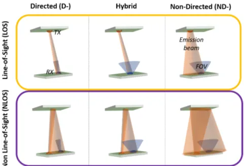
Figure 2.2: OWC links possible configuration. TX is the transmitter, RX is the receiver and FOV is the Field-of-View.
7. The destination, which is the final target of the information.
In this chapter, we will focus on the building blocks that are necessary to the realization of a communication system, describing how this general scheme applies to the optical wireless case.
A more detailed description of the specific OWC applications will be pre-sented in the next chapters.
2.1
System configurations
Link geometry deeply influences OWC systems performance and the device choice. Based on TX/RX Field-of-View (FOV) and link directionality, we can define 6 different configurations (see Fig. 2.2). Related to FOV, links can be defined as Directed (D-) or Non-Directed (ND-). Link directionality can be defined Line-of-Sight (-LOS) for a direct communication between TX and RX or as Non-Line-of-Sight (-NLOS) if the optical link is maintained through a reflected or diffused beam.
• In Directed Line-of-Sight (D-LOS) (see Fig. 2.2, top left) TX and RX are directed along the same optical axis in two opposing directions
2.1. SYSTEM CONFIGURATIONS 11 with no obstacles in between. The communication channel is com-pressed in a narrow beam by using a small angle emitter at TX side and a narrow FOV at RX side. This configuration is usually adopted for point-to-point topology. In terms of optical power, this geometry is the lowest power-demanding due to the high confinement of the signal in a narrow beam and hence a high power density, a reduced noise from ambient light and multipath-induced signal distortion at the RX side. However this configuration requires a careful alignment of TX and RX reducing the link mobility or requiring a tracking system. Moreover, the breaking of the LOS by intervening objects (shadowing) disrupts the communication, heavily limiting the use of this configuration in many environments.
• In order to increase the link robustness to misalignment and shadow-ing, Non-Directed Line-of-Sight (ND-LOS) configuration (top right) represents a valid alternative to implement point-to-multipoint and broadcast topologies. In ND-LOS systems, using a wider emission angle and a wider RX FOV, the need for TX-RX careful alignment is usually removed, allowing for devices mobility. However, link robust-ness is improved at the expenses of power efficiency, background noise and multipath dispersion rejection, affecting overall link performance. • A trade-off between these configurations is represented by the hybrid Line-of-Sight (LOS) configuration (top central), which uses either narrow TX emission angle or RX FOV. In particular in High Toler-ance DLOS (HT-DLOS), a larger emission angle and a narrow RX FOV can be used to achieve high communication performance while providing robustness to misalignment, useful to realize a point-to-point topology requiring just a coarse alignment. The opposite situation can be used in multipoint-to-point or star topologies.
• Directed Non-Line-of-Sight (D-NLOS) systems (bottom left), due to use of reflected paths are more robust to both shadowing and misalignment than D-LOS systems, although having lower perfor-mances. However, the use of direct configuration still poses a major constrain to mobility related to the need for alignment, even if not so accurate.
• Non-Directed Non-Line-of-Sight (ND-NLOS) configuration, also defined as diffused, is the most robust configuration (bottom right) regarding both alignment and shadowing, due to the use of wide
emis-sion TXs and wide FOV RXs. It is obvious that the high optical path loss and multipath dispersion, together with a higher degree of back-ground noise, greatly reduces the performance of diffused systems. Still, this configuration is considered the more versatile in terms of achievable topologies and applications.
• Hybrid NLOS configuration (bottom central), like their LOS coun-terparts, represents trade-offs between direct and non-direct perfor-mances and robustness, leveraging different TX emission angle and RX FOV.
2.2
Transmitting devices
A typical optical TX employs a semiconductor diode that emits light. When this diode is forward biased, electrons flow in the semiconductor, recombin-ing with the holes within. Electron-hole recombination generates photons by electroluminescence effect, with an energy, and hence a wavelength, de-pendent on the semiconductor band-gap. The optical emission can be spon-taneous, as in LEDs and Organic Light Emitting Diodes (OLEDs), or stim-ulated, as in lasers, like Laser Diodes (LDs), Distributed FeedBack (DFB) lasers and Vertical Cavity Surface Emitting LASERs (VCSELs).
This thesis will deal only with OWCs based on LEDs. In what follows we will then focus our attention only on this type of sources.
2.2.1 Electrical characteristics of diodes
From an electrical point of view, diodes are non-linear devices, with an I-V characteristic (see Fig. 2.3) that obeys to the Shockley equation [16]
Id= I0[exp(qVd/ηkBT ) − 1] (2.2.1)
where kB is the Boltzmann constant, q is the electron charge, T is the
junction temperature, η is the diode ideality factor that depends on the semiconductor, Vdis the junction voltage and I0 represents the device
leak-age current when biased in the reverse direction (Vd < 0).
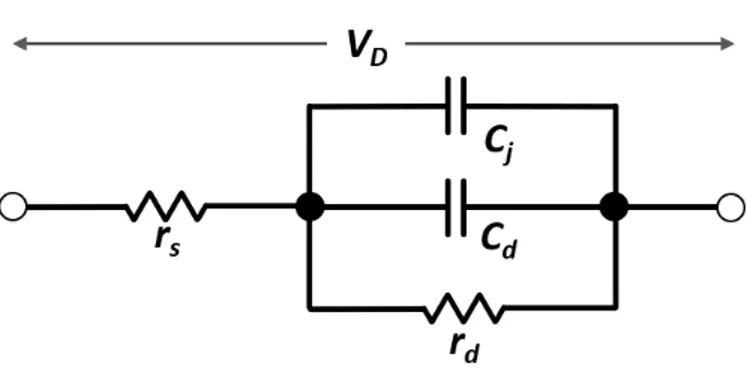
From the I-V characteristic (see Fig. 2.3) it can be easily seen that diodes are non-linear devices. Hence, the use of high-amplitude signals may cause distortions due to clipping effects. By keeping the device in the small signal regime is possible to avoid non-linear effects that appear at higher voltages. In small signals regime, diodes can be modeled as the forward biased (Vd> 0)
2.2. TRANSMITTING DEVICES 13
Figure 2.3: I-V characteristic of a semiconductor diode: Vbr is the device
breakdown voltage, Vd is the diode voltage knee. Three colored areas
rep-resent the three diodes regimes.
rdis the diode small signals resistance.
The diode intrinsic capacitance is modeled as the sum of the junction capacitance Cj = dQj dV ,
related to the variation of the total depletion-layer charge Qj at the P-N
in-terface as a function of the applied voltage V , and the depletion capacitance Cd=
q kBT
τTId,
related to charge diffusion and storage effects in the bulk of the semiconduc-tor, with τT being the minority carriers total transit time and Idthe forward
current.
For lighting applications the value of Idcan be very high, thus the resulting
intrinsic capacitance, C = Cj + Cd, of the device can be very large. By
denoting the series resistance rs, it is possible to calculate the diode time
constant τ = rsC.
So the −3dB electrical cut-off frequency of the device is fel=
1 2πτ ∼
0.35
τ (2.2.2)
Common LEDs used for lighting show typical values in the 10 − 20 M Hz range, while VCSELs can go up to > 10 GHz.
Figure 2.4: Diode forward bias equivalent circuit: Vd is the voltage applied
to the diode, rs is a general series resistance, rd is the diode’s resistance
for small signals, Cj is the junction capacitance and Cd is the diffusion
capacitance.
2.2.2 Light Emitting Diodes
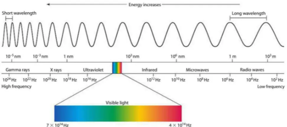
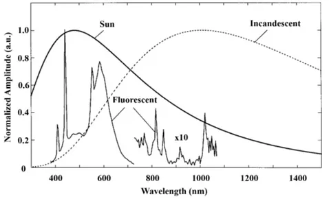
The visible light, the region of the electromagnetic spectrum which is de-tectable by the human eye, ranges from approximately 380 nm and 780 nm, as presented in Fig. 2.5. Single-color LEDs are easy to obtain but lighting applications require a bright white light. The realization of a white LED source can take two different designs. The simpler and older version, named RGB-LED, is made by proportionally mixing red, green and blue LED chips together with combining optics to blend the three emissions. The human eye perceives this mixture as white light, unable to separate the single colors. Another design, named Phosphor LED (Ph-LED), uses a blue Gallium Ni-tride (GaN) LED coated by a Yttrium Aluminum Garnet (YAG) phosphor layer. The blue light emitted from the LED is partially absorbed by the phosphor layer that re-emits the light at a longer wavelengths, producing a white radiation.
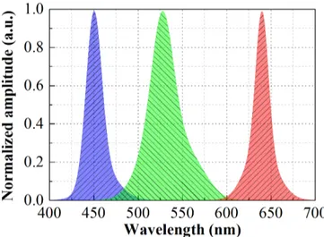
In terms of electrical bandwidth, single colored LEDs, like those used in RGB design, have an approximated value of 12 M Hz. In a Ph-LED, the slow response of the phosphor layer greatly limits the cut-off frequency to 2 − 3 M Hz, as demonstrated by the small-signal frequency response in Fig. 2.6. This two designs lead to distinctive optical spectra distributions p(λ), the former Fig. 2.7 characterized by three separated peaks, one for each color, the latter shows the singular peak of the blue component to-gether with the broad emission spectrum of the phosphors at higher wave-lengths Fig. 2.8. It is clear, from Fig. 2.7 and Fig. 2.8, that LEDs’s p(λ)
2.2. TRANSMITTING DEVICES 15
Figure 2.5: Classification of the electromagnetic spectrum as a function of radiation wavelength or frequency.
Figure 2.6: Normalized frequency response of a Ph-LED. The grey dashed line represent the response of the white light originating by the phosphor layer. The blue line is the original response of the blue LED below the phosphor, obtained by optically filtering the white emission.
Figure 2.7: Normalized optical amplitude spectral distribution of a RGB-LED. The three peaks refer to the red (right), green (center) and blue (left) LED emissions.
Figure 2.8: Normalized optical amplitude spectral distribution of a Ph-LED. Two different types of LEDs are presented, based on their Correlated Color Temperature: a cold white (higher 450 nm peak, in blue) and a warm white (higher 600 nm peak, in yellow) Ph-LEDs.
2.3. RECEIVING DEVICES 17 has a peaked emission with an optical bandwidth of 20 − 50 nm. This value is narrower than that of many common lighting sources (e.g. incandescent lamps) but still wider than monochromatic sources (e.g. lasers).
2.3
Receiving devices
In emitting diodes, light is produced by the radiative recombination of an electron-hole pair, in a transition between conduction and valence band. This generates a photon of a given wavelength, dependent on the energy gap. By using a different structure, a diode can also be used for the oppo-site process.
An impinging external photon is absorbed by an electron in the valence band giving it enough energy to move to the conduction band and generating an electron-hole pair. Applying an external field is then possible to move the charge carriers in the semiconductor and generate a current. This devices are called PDs and can be used for light detection by measuring the photo-generated current.
Although various other devices can be used for photon detection, e.g. pho-totubes or photomultipliers, here we will focus only on PDs, being the only devices covered in this thesis.
2.3.1 Positive-Intrinsic-Negative diodes
In Positive-Intrinsic-Negative (PIN) diodes, a region of undoped intrinsic semiconductor is introduced between two doped regions, P and N [17]. When reverse biased, the electrical field propagates through almost the entire in-trinsic region. Thanks to photoelectric effect, absorbed photons create free charge carriers in the intrinsic region. Hence, a PD exposed to light gener-ates a photocurrent due to the transport of these charge carriers.
As we have seen in Section 2.2.1, carrier transit time τT plays an important
role in limiting the frequency response of PDs in optical communications. However, in order to increase the light harvesting capabilities of the RX, in OWC the employed devices have relatively large areas; that gives an increase of the device capacitance and hence reduces the PD’s electrical frequency response.
2.3.2 Avalanche Photodiodes
The general structure of Avalanche Photodiodes (APDs) is very similar to that of PIN PDs, with the main difference being the number of electron-hole
pair generated for each absorbed photon. In APDs, the depletion region is designed to have a high electrical field in order to provide an acceleration to the generated carriers. Due to the augmented kinetic energy, the impact of the accelerated charge carrier with the semiconductor lattice creates new free charge carriers in the material. This field-induced avalanche effect multiplies the number of generated carriers per photon.
The main disadvantage of the avalanche process is the generation of an excess of shot noise caused by the amount of current flowing into the diode. In OWC, this effect combined with common high intensity ambient light, can degrade the quality of the signal, as explained in Section 2.4. Moreover, due to a non-unitary photocurrent gain, APDs show strong non-linear behaviour as a function of the incident optical power, unlike PINs that show an almost linear behaviour over a wide range of input optical intensities. For this reason, APDs are usually limited to applications that are more robust to their poor linearity, like in systems based on digital signals.
2.3.3 Camera Image Sensors
Camera Image Sensors (CISs), used in many applications, are constituted of arrays of photodetectors that can record not only the intensity of the light focused on it but a complete image. VLC system exploit the imaging capacity, together with the ability to distinguish different colors, to realize compact Multiple Input Multiple Output (MIMO) and Color Shift Key-ing (CSK) systems [18].
In these devices the technologies adopted are mainly two: the Complementary Metal Oxide Semiconductor (CMOS) and the semiconductor Charge-Coupled Device (CCD).
A CMOS sensor is based on an array of PIN PDs, while in CCD image sensor, p-doped Metal Oxide Semiconductors (MOS) capacitors are used as pixel light detectors. When the capacitor bias goes beyond the inver-sion threshold incoming photons are converted into electron charges at the semiconductor-oxide interface. The generated charge carriers are initially stored and then transported in a second step to a serial output register to extract the pixels information.
The two technologies also differ for pixel readout modes. CCD cameras often use Global Shutter (GS) readout mode, exposing simultaneously every pixel at the same instant. The signal from each pixel is transferred serially to a single Analog-to-Digital Converter (ADC) only after the complete frame has been exposed (Fig. 2.9). The delay introduced depends on the sensor size and limits the camera frame rate and hence the device bandwidth as
![Figure 1.3: US RF spectrum allocation [5]](https://thumb-eu.123doks.com/thumbv2/123dokorg/2928615.18910/20.918.244.752.199.533/figure-us-rf-spectrum-allocation.webp)
![Figure 1.4: Demand for wireless data traffic recorded and forecast [9]](https://thumb-eu.123doks.com/thumbv2/123dokorg/2928615.18910/21.918.160.678.204.457/figure-demand-wireless-data-traffic-recorded-forecast.webp)