A
A
l
l
m
m
a
a
M
M
a
a
t
t
e
e
r
r
S
S
t
t
u
u
d
d
i
i
o
o
r
r
u
u
m
m
–
–
U
U
n
n
i
i
v
v
e
e
r
r
s
s
i
i
t
t
à
à
d
d
i
i
B
B
o
o
l
l
o
o
g
g
n
n
a
a
DOTTORATO DI RICERCA IN
SCIENZE CHIRURGICHE
Ciclo XXVII
Settore Concorsuale di afferenza: 06/E3
Settore Scientifico disciplinare: Med 29
TITOLO TESI
New Application of Piezoelectric Ultrasounds
in Maxillo-facial bone surgery
Presentata da:
Dott. Luigi Piersanti
Coordinatore Dottorato
Relatore
Prof. Andrea Stella
Prof. Claudio Marchetti
Index:
1
Introduction
3
1a Background
3
1b Utrasonic device History
4
2
Aim of the study
7
3
Maxillo-Facial Surgery field of Piezosurgery application
8
3a Orthognatic Surgery
8
3b Oncologic Surgery
16
3c Extractive Surgery
31
4
Appendix
40
4a Preprosthetic Surgery
41
4b Orthodontics Surgery
44
4c Pediatric Surgery
45
4d Oral Surgery
48
1) Introduction
1a) Background
In the last decades maxillo-facial surgery techniques have rapidly developed due to request of less-invasive surgery and due to the introduction of osteointegration and its increasing use in anatomically compromised site in preprosthetic surgery. So the research’s effort in cranio-facial surgery were focused on major level of precision and safety in bone surgery in order to reduce patient’s disconfort. (1)
Up until now, bone as been cut by either manual or motorized instrument, manual instrument offer good control when they are used to remove small quantities of bone from zone with minimal mineralization. However, manual instruments are difficult to control in the cortical bone especially in case where a precise cut is require. For the most part they are used for performing coarse cuts on large portion of bone.
Motorized instruments, however are used when the bone is very compact. Their function is based on the conversion of electric or pneumatic energy into mechanical energy used for cutting with either a bur or a saw.
These instruments generates a significant amount of heat in the cutting site that can be reduced to a minimum with water irrigation.
The overheating of the nearby tissue in a cutting site can alter the healing response; reduced rotational velocity can limit heat production by attrition but inevitably affects the cutting action.
The use of motorized cutting instruments reduces tactile sensitivity. A minor rotational speed is usually compensated for by an increase in manual pressure. This results in the consequent increase of macro-vibrations of the instrument which reduce surgical sensitivity.
This particularly problematic when passing bone from the cortical bone to the spongeous bone of soft tissue, such as it is done during an osteotomy above the mandibular canal or when a bony window is opened during maxillary sinus surgery. The force necessary to cut the dense cortical bone must be immediately reduced when the structure become less dense with the risk of injuring the underlying tissue.
Power ultrasonics was first introduced in dentistry in 1952 when Catuna used an industrial ultrasonic drilling machine to cut cavities in extracted teeth [11]. First patented by Lewis Balamuth in 1945 [2], and reported upon in 1951 [3,4], the industrial device was originally designed to cut hard and brittle materials such as tungsten carbide, glass and ceramics. Cutting was achieved through the application of high intensity ultrasound to an abrasive slurry on the surface of the work piece, which gradually ground it away. Catuna and Balamuth's innovative use of a novel industrial device and subsequent trials lead to the development of a specialised dental device that operated on the same principles as its industrial counterpart [5]. However, even though many surgical benefits over conventional air powered drills were promised by this ultrasonic device, the requirement for an abrasive paste restricted the view of the dental operator while its high cost may have hampered its overall success.
1b) Ultrasonic Device History
The first application of ultrasonics in the periodontal treatment of oral prophylaxis was reported by Zinner in 1955 [6]. Initial trials of early ultrasonic scalers produced favourable results over hand instruments, reducing procedure time, patient discomfort and damage to soft tissue surrounding the tooth. Despite these findings strengthening the case for the adoption of ultrasonic devices for routine prophylaxis treatment, it was also found they could potentially scratch the root surface and dentine of the tooth if applied to the tooth surface with a large force. However, it should be recognised that applying the vibrating device with large levels of force to the tooth surface is unnecessary and illustrates an incorrect use of the device. Apart from damaging tissue, the application of high pressures also reduces vibrational amplitude of the ultrasonic device reducing its performance [7,8]. Parallel to the studies on dental scaling, investigations into the potential use of ultrasonicinstruments in bone cutting procedures were undertaken during the 1950s. Although the very first devices, such as those reported by Balamuth, relied on an abrasive slurry, towards the end of the 1950s Richman discussed the use of an ultrasonic device in dentistry which
operated without slurry [9], applying the device to various endodontic treatments such as root planning. However, the use of ultrasonic devices in endodontics was significantly improved twenty years later by Martin through the application of a biological agent enhancing microorganism eradication, during root cleaning and disinfection [19, 11]. A few years after Richman, Mararow [12] and McFall et al [13] also reported upon the use of ultrasonic devices directly cutting bone tissue without the requirement of an abrasive slurry. These novel bone cutting trials utilising ultrasonics during the 1950s and 1960s, whether they required an abrasive slurry or not, discussed the advantages and disadvantages of ultrasonic devices when compared to traditional bone burs or saws. Richman reported that in 32 clinical cases where an ultrasonic device was used to plan alveolar bone (bone surround the tooth), healing was uneventful without postoperative complications . Richman also noted increased patient acceptance of the ultrasonic method after a reduction in patient discomfort from the postoperative site, an observation independently made by Postle during the same year . Reports throughout the following decades further discussed advantages and disadvantages of ultrasonic osteotomy. However, even though Mararow [12] indicated that the ultrasonic devices could inhibit bone healing, further studies by McFall et al [13] reported little difference between recovery times between traditional and ultrasonic devices. Aro et al [15] concurred with McFall et al and Horton et al, although finding that initial healing was slower in bone cut ultrasonically. Comparisons between studies investigating the performance of ultrasonic devices with oscillating burs or saws during the 1970s and early 1980s are often difficult to directly compare due to the differences in the ultrasonic devices as well as the location and type of bone dissected. The use of cooling fluid is discussed in these studies, although not always providing a consistent opinion as to whether it should be used in operation or not. Aro et al [15] reported that in 1974 Polyakov et al stated that the temperature of the cutting site with an ultrasonic saw without the presence of a cooling fluid did not exceed 780C, however, the value that Picht et al reported in 1977 was considerably higher at 1500C. Picht et al also reported that during bone dissection with a bone saw, the temperature reached 600C, however with coolant the temperature of bone during cutting with both the ultrasonic device and bone reached 400C. From this study Picht et al illustrated that without cooling fluids ultrasonic devices had the potential to raise the temperature of bone higher than traditional bone saws,
however the presence of cooling made temperature increases comparable. Picht et al therefore derived the same conclusions as McFall et al [13] that cooling fluid was necessary during ultrasonic cutting.
Many modern ultrasonic bone cutting devices deliver a fluid, generally through an internal channel located through the handpiece of the ultrasonic device, to an outlet positioned near the cutting blade and cutting site. This aims to cool both the cutting blade and surgical site, thus preventing narcosis, and to assist the removal of tissue debris from the tool-tissue interface, keeping the site clear for the surgeon to view while also removing any swarf which could, through frictional heating, could burn and damage the edge of the dissection [5,]. Studies have shown greater promotion of osteoblast (cells responsible for bone formation) in dissected regions without osteonecrosis and burnt swarf. This is probably due to intact and unblocked Haversian channels (or canals), which allow oxidation and communication between the dissected area and sites that produce osteoblasts, to permit the cells and proteins necessary for recovery to reach the dissected regions quicker than if they were damaged through osteonecrosis or blocked with burnt debris [14,15].
Although ultrasonic oral prophylaxis had become a mainstream periodontic treatment by the 1990s, the use of ultrasonics in osteotomy and osteoplasty (the repair of bone) had not progressed from experimental instruments and trials. The success of dental scaling devices may be partly due to the development from early scaling tips, which were bulky, to slender tips capable of accessing hard to reach areas. However, the ability to manufacture slender and reliable inserts is also important for the control of tissue heating during osteotomy.
It was not until 2001 that the first commercial ultrasonic device specifically designed for bone cutting applications entered the market. Known as the Piezosurgeryr Device, this system built upon ultrasonic scaler technology and was developed through a collaboration between of a maxillofacial surgeon, Vercellotti, and Italian company Mectron S.p.A [16]. Possibly two important factors can account for the instrument's success; the collaboration between the surgeon and the engineering company, and advancements in transducer control electronics. The partnership between the surgeon and the design company allowed the product to be developed with direct influence from the user. This ensured that the device would be practical (early attempts at bone cutting devices were difficult to use and cumbersome) and more likely to be accepted by the surgeon [17, 18]. Meanwhile, during operation, the application of different pressures by the surgeon, the presence of cooling fluid and heating within the piezoceramics elements due to extended use are factors which could cause the device's resonant frequency to change. This could lead to difficulties in tracking it the resonant frequency, however advances in modern electronics has allowed this to be adequately solved. The application of a 50kHz pulse every 10ns to the excitation frequency of the Piezosurgery Device transducer is a novel design feature which assists the device to efficiently cut bone efficiently [16].
[1] Lundgren S, Moy P, Johansson C, Nilsson H. Augmentation of the maxillary sinus floor with particulated mandible: a histologic and histomorphometric study. Int J Oral Maxillofac Implants. 1996 Nov-Dec;11(6):760-6
[2] T. Thoe, D. Aspinwall, and M. Wise, \Review on ultrasonic machining," International Journal of Machine Tools and Manufacture, vol. 38, no. 4, pp. 239{255, 1998.
[3] A. Cohan, \New method machines: sintered carbides, sintered borides, hardened tool steels," Joural of Metals, vol. 3, pp. 219{217, 1951.
[4] S. Kelley, \Hard, brittle materials machined using ultrasonic vibrations," Materials and Methods, vol. 34, pp. 92{94, 1951. [5] L. Balamuth, \Ultrasonics and dentistry," Sound: Its Uses and Control, vol. 2, no. 2, pp. 15{19, 1963
[6] D. Zinner, \Recent ultrasonic dental studies, inceeding periodontia, without the use of an abrasive," Jorunal of Dental Research, vol. 34, no. 5, pp. 748{749, 1955.
[7] W. Johnson and J. Wilson, \The application of the ultrasonic dental unit to scaling procedures," Journal of Periodontology, vol. 28, pp. 264{271, 1957.
[9] M. J. Richman, \The use of ultrasonics in root canal therapy and root resection," Journal of Dental Medicine, vol. 12, no. 1, pp. 12{18, 1957.
[10] A.Walmsley, W. Laird, and P. Lumley, \Ultrasound in dentistry. part 2{periodontology and endodontics," Journal of Dentistry, vol. 20, no. 1, pp. 11{17, 1992.
[11] H. Martin, \Ultrasonic disinfection of the root canal," Oral Surgery, Oral Medicine, Oral Pathology, vol. 42, no. 1, pp. 92{99, 1976.
[12] H. Mararow, \Bone repair after expwerimentally prodced defects," Journal of Oral Surgery, vol. 18, pp. 107{114, 1960. [13] T. McFall, G. Yamane, and G. Burnett, \Comparison of the cutting e_ect on bone of an ultrasonic cutting device and rotary burs," Journal of Oral Surgery, vol. 19, pp. 200{209, 1961.
[14] J.-L. Beziat, J.-C. Bera, B. Lavandier, and A. Gleizal, \Ultrasonic osteotomy as a new technique in craniomaxillofacial surgery," International Journal of Oral Maxillofacial Surgery, vol. 36, pp. 493{500, 2007.
[15] H. Aro, H. Kallioniemi, A. Aho, and P. Kellokumpu-Lehtinen, \Ultrasonic device in bone cutting: A histological and scanning electron microscopical study," Acta orthopaedica Scandinavica, vol. 52, pp. 5{10, 1982.
[16] Vercellotti T: Technological characteristics and clinical indications of piezoelectric bone surgery. Minerva Stomatol 53:207, 2004 [17] M. Labanca, F. Azzola, R. Vinci, and L. F. Rodella, \Piezoelectric surgery: Twentyyears of use," British Journal of Oral and Maxillofacial Surgery, vol. 46, no. 4, pp. 265{269, 2008.[18] M. F. McKneally, \Ethical problems in surgery: Innovation leading to unforeseen complications," World Journal of Surgery, vol. 23, no. 8, pp. 786{788, 1999.
2) Aim of the study
Piezoelectric instrumentation seems to offer 3 important advantages for cutting bone structures. Be more precise because it is produced by micro-vibrations from the cutting insert.
Be safer because the ultrasonic frequency used, does not affect soft tissue.
Thirdly, the less invasive cutting action produces minor tissue damage and consequently probably a better healing The aim of this study is to evaluate the effectiveness of piezoelectric device capability in maxillo-facial surgery, in order to take advantage of these favourable capacity.
So considering the several potential application of the piezoelectric technology, we would like to design a protocol in order to verify how this new device can modify the surgical technique, the surgical time, the patients healing and its quality of life.
3) Maxillo-Facial Surgery field of Piezosurgery application
In this protocol, we tested Piezosurgery device in several maxilla-facial surgery fields:Orthognatic Surgery Oncologic Surgery Extractive Surgery
3a) Orthognatic Surgery
Perform Le Fort I osteotomy or mandibular bone cut in this patients, request precise and safe cut not only because the several vascular and nerve structures are involved but also because millimetre movements are needed in order to satisfy the surgical plans.
(A, B) Le Fort I Osteotomy performed with Piezosurgery Device
A B
(C, D) Maxillary Tripartition, thin Piezosurgeru tip can easily go through the teeth roots
Obviously Piezosurgery is a strong advice in this situation and we try to use this strength property to take a step forward in orthognathic plan and surgery performance, trying to plane a waferless upper maxilla reposition designed customized titanium plates and cutting guide with a small osteotomy line almost exploitable by the thin Piezosurgery insert.
So the purpose of study was to develop a CAD-CAM technique that would enable fabrication of surgical cutting guides and titanium fixation plates to allow the upper maxilla to be repositioned correctly without a surgical splint. The surgical cutting guides were used to pilot the virtually planned osteotomy line during surgery and the custom-made fixation titanium plates allowed the maxilla to be repositioned as desired.
Materials and Methods
To evaluate the utility of this new procedure, the reproducibility of computer-aided surgical planning was analyzed in a group of patients who underwent orthognathic surgery at the Oral and Maxillo-facial-Surgery Unit of the S. Orsola Malpighi University Hospital (Bologna, Italy). The present results were compared with previously published data from a sample of similar patients in whom maxillary repositioning was performed using a standard intraoperative dental splint and a surgical navigation system.(1) The present protocol was submitted to and approved by the institutional review board (ethical committee approval number 238/2012/0/Disp PL02). At all times, the authors complied fully with the tenets of the World Medical
Association Declaration of Helsinki as they apply to medical research protocols and ethical conduct.
Ten patients were recruited during presurgical orthognathic clinical examinations conducted in the authors’ surgical unit. All patients were fully informed about the planned procedure and gave written informed consent.
A complete CAD-CAM workflow for orthognathic surgery has 3 steps: 1) virtual planning of the surgical treatment,
2) CAD-CAM and 3D printing of customized surgical devices, and 3) computer-aided surgery.
VIRTUAL PLANNING
Planning began with acquisition of a cone-beam computed tomographic (CBCT) scan of the craniofacial skeleton and associated soft tissue of each patient. Patient-specific imaging data were obtained using a New Tom VGI CBCT scanner (QR, Verona, Italy). Voxel-based data were acquired using a slice thickness of 0.625 mm, slice spacing of 0.312 mm, a gantry tilt of 0_, and a resolution of 512 _ 512 pixels. Data were exported in Digital Imaging and Communications in Medicine (DICOM) format and processed (by the surgeon) using Surgicase CMF 5.0 software (Materialise, Leuven, Belgium). After choosing a suitable threshold value, the software facilitated volume segmentation and creation of 3D virtual models of the maxillofacial skeleton and facial soft tissues. Dental models were incorporated with the 3D
reconstruction of the CT scan using virtual fiducial markers and a best-match algorithm for surfaces This allowed the surgeon to plan surgery completely in 3 dimensions. Cephalometric analysis was performed in 3 dimensions, 2 as were simulation of the desired movements of the maxilla and mandible and, if required, simulation of the appearance of soft tissues after surgery. Planned movements were exported as numerical data and sent to the laboratory responsible for CAD-CAM device production, together with DICOM data from the CT scan.
CAD-CAM AND 3D PRINTING
CAD-CAM devices were produced by SINTAC (Padua, Italy). Surgical planning data sent to the laboratory were used to design and manufacture customized surgical devices; these were cutting guides and bone fixation plates. CAD of the surgical devices used Rhino 4.0 software (Robert McNeel & Associates, Seattle, WA). DICOM data were used to generate a 3D virtual model of the facial skeleton of each patient using a specific 3D environment. Next, customized cutting guides were designed to allow the surgeon to precisely transfer the location and orientation of the osteotomy line from a virtual plan to the real surgical environment. Cutting guides were virtually modeled, with reference to the 2 sides of the maxilla, and were designed to cover most bone surfaces exposed during surgery. The guides followed the natural curvatures of the maxillozygomatic buttress and the anterior maxillary walls. The authors assumed that this would maximize stability, adhesion, and correct positioning during actual surgery. The exact position of the osteotomy line was drawn by each surgeon using a Web-based remote-control service (e-works meeting; e-works srl, Campogalliano, Modena, Italy) available in the SINTAC laboratory. Eight holes (2.0 mm in diameter) were inserted to allow guide fixation using titanium screws and a very thin osteotomy line was designed in order to be as much as possible precise (Fig 1A). All holes for screw fixation were placed carefully to ensure that the roots of teeth would not be damaged when the screws were inserted. Customized bone fixation plates constituted the second group of components. Such plates permit repositioning of the upper maxilla in a planned location. Plates were designed to ensure the desired sagittal, transverse, and vertical movements of the maxilla. Planning data were numerically sent to the SINTAC laboratory and inserted into the 3D virtual environment used in the design. Each virtual osteotomized maxilla was created using patient-specific data with reference to a standard 3D coordinate system based on the Frankfurt plane (right orbital and left orbital; the midpoint was between the right and left poria). All virtual operations were viewed by the surgeons using Web-based remote connections. In this manner, the entire set of planned spatial movements of the maxilla was stored completely in the fixation plate. The holes created to position the cutting guides also were used to fix the plates (the transfer principle; Fig 1B).
1A) Presurgical Cutting guide plane 1B) Presurgical custom made plates plane
Stereolithographic (STL) files of the cutting guides and plates were manufactured by direct metal laser sintering (DMLS) using the EOSINT M270 system (Electro- Optical SystemsGmbH,Munich, Germany). DMLS fuses metal powder into a solidmass and then melts the mass locally using a focused laser beam. As in other additive manufacturing technologies, the components were constructed in layers. Each cutting guide (Fig 2A) was created using a 3D Dimension Soluble Support Technology (SST) RP machine (Stratasys, Eden Prairie, MN). The bone fixation plates (Fig 2B) were composed of EOS Titanium Ti64 (Electro-Optical Systems), a pre-alloyed Ti6AIV4 alloy available in a fine-powder form, which exhibits excellent mechanical properties and corrosion resistance, has low specific weight, and is highly biocompatible, rendering the material particularly suitable for the production of biomedical implants. To allow surgeons to engage in preoperative training and to facilitate a better understanding of the authors’ approach, ‘‘biomodels’’ of each maxilla (before surgery and after the planned osteotomy) were manufactured directly on the SST RP machine. All physical components were sent to the surgeons before surgery. The surgeons also received STL files showing the cutting guides in the planned positions; these were used during computer-aided surgery.
2A) Cad-Cam Cutting Guides 2B) Titanium custom made plate
COMPUTER-AIDED SURGERY
Upper maxilla repositioning was performed in a waferless manner using a CAD-CAM device under the control of a navigation tool; the authors used the concept of simulation-guided navigation.(1) The navigation tool was the eNlite Navigation System featuring the iNtellect Cranial Navigation Platform 1.0 (Stryker, Freiburg, Germany). The navigation
adapted for repositioning the upper maxilla without a navigation system. The upper maxilla was accessed through an intraoral incision. The cutting guides were introduced into the surgical field and stabilized in the correct position using the good anatomic engagement afforded by the natural curvature of the maxilla-zygomatic buttress and the anterior maxillary walls. Use of the navigation tool ensured correct positioning of the guide. The boundaries, surfaces, and screw holes of the cutting guides were used as reference points. When the surgeon was encouraged, after the performance of a navigation check, to move the guide slightly from the initial position (ie, after manual placement), that event was recorded. Each cutting guide was fixed in place with titanium screws (Fig 3A) and a piezoelectric saw (tip diameter, 0.55 mm, Genova, Italy) was used to perform the osteotomy. The cutting guides were removed and the Le Fort I osteotomy was completed. Next, bone fixation plates were used, 1 on each side, to reposition the upper maxillary bone in the correct location. As mentioned earlier, the fixation plates were designed to allow attachment to the maxilla using the holes through which the cutting guides had been fixed. This ensured that the relative positions of the 2 components were mutually correct (Fig 3B). Many holes are included in the plate so that if a hole fails, the surgeon can use another hole in the same plate. A single surgical team performed all procedures and the roles played by team members did not change throughout the study.
3A) Cutting guide fixated with screws 3B) Cad-Cad Custom made plates after Le Fort I osteotomy
EVALUATION OF ACCURACY To evaluate the reproducibility of the CAD-CAM orthognathic surgical method, the virtually planned and actually achieved positions of the upper maxilla were compared. Postoperative CT scans were obtained 1month after surgery, using the same machine for all patients, and data were compared with those of the preoperative CT scans. After choosing suitable threshold values, each DICOM dataset was processed to create a 3D model of the postoperative maxillofacial skeleton (threshold value, 300 HU) and 3D model of the bone fixation plates alone (threshold, 1,900 HU). Pre- and postoperative datasets were compared using Rapidform XOS2 software (INUS Technology, Seoul, Korea) by evaluating differences between the virtual and actual positions of the upper maxilla and fixation plates with the aid of the Hausdorf function. Each surface deviation was represented on a color map Overlap errors were evaluated using a threshold value smaller than <2 mm, and the frequency of such errors was used as a measurement of accuracy. By this definition, the accuracy was 100% in 7 patients (range in all patients, 62 to 100%; median, 92.7%). The error interval was largest in patient 1 (_3.4 to +3.2 mm) and smallest in patient 6 (_0.07 to +0.02 mm). The initial positions of the cutting guides, guided by the navigation check, were found to be correct in 7 cases
and required small adjustments in 3 cases. The number of holes in the plates was always sufficient to allow stable fixation, even when at least 1 hole had been drilled to a diameter that did not allow a screw to become fixed. All plates were functional; no standard plate was substituted intraoperatively. All patients healed uneventfully; no infection of the DMLS bone fixation plates was noted.
Overlap of preoperative planes and postoperative CBCT with a color map
Discussion
To ensure good esthetic and functional results after orthognathic surgery, it is essential to correctly reposition the upper maxilla in line with the preoperative plan. Accurate maxillary relocation is the key feature of orthognathic surgery, because this bony segment is located in the center of the face and usually guides all movements of the facial bones, particularly those of the opposite jaw. However, the optimal method of 3D control of intraoperative maxillary movements during surgery remains controversial. Traditionally, the maxilla is repositioned intraoperatively using surgical splints placed based on intra- or extraoral measurements. Such measurements are rather inaccurate, and the splints are typically constructed manually using surgical models. Many sources of potential error are apparent, and unsatisfactory outcomes, with maxillary malpositioning as great as 5 mm, can ensue.(3) However, most maxillofacial
surgeons worldwide still use this method. A 3D preoperative plan, loaded as a 3D object in the software of the navigation system, allowed the surgeon to visualize any mismatch between the native bone and the planned position of the osteotomized fragment and to determine in real time whether the actual repositioning agreed with that planned. Using this method, the mean reproducibility of the preoperative surgical plan was 86.5% (error, <2 mm). Such results were particularly promising for vertical control of the maxilla, because this method, despite having the intrinsic limitation of the need to check many reference points at different times, was the first serious attempt to introduce strict reproduction of such vertical movement. Nevertheless, such navigation has not become a standard procedure, although many groups have worked with this technique in recent years. This could reflect the high costs of commercial navigation systems and the need to invest in research to overcome current technical limitations. However, splints fabricated using modern CAD-CAM techniques are finding applications in orthognathic surgery. Such splints are a new affordable solution to bridging the gap between virtual planning and the operating theater. It is indeed true that the use of virtual casts improves splint accuracy, especially for splint correlation with the skeletal structure. However, the use of splints does not improve vertical control of the maxilla.(4) To address this problem, Zinser et al1 described a system, adopted in 8 patients, to reposition skeletal segments using 3 sequential occluding wafers. The first splint was used to define reference points on the skull, the second to reposition the maxilla, and the third for the final occlusion. The advantage of this technique was that the maxilla could be independently relocated in all positions, allowing, according to the researchers, precise vertical and horizontal leveling in relation to the cranial base. Polley and Figueroa (5) introduced the concept of occlusal-based devices to transfer virtual surgical planning to the operative field. An initial drill guide was used to establish stable references or landmarks. After mobilization of the skeletal segment, a final positioning guide, referable to the drilled landmarks, was used to transfer the skeletal segment in line with the dictates of virtual surgical planning. The maxilla was fixed in a traditional way using manually bended plates. The device was designed using 3D CAD-CAM technology and manufactured using stereolithographic techniques. The device was used successfully to treat 24 patients. Bai et al (6) described a case series in which they used a CAD-CAM locating guide and manually pre-bent titanium plates on stereolithographic model. In a preliminary study, Li et al (7) described their experience in 6 patients using a new CAD-CAM template to guide the osteotomy and reposition the upper maxilla during bimaxillary orthognathic surgery.
Manual bending of plates was used to fix the maxilla. Preliminary results obtained by comparing postoperative CT scans with data from the virtual plane showed that the ‘‘errors’’ in maxilla positioning were smaller than 1 mm. However, all these protocols are relatively complex and time consuming compared with the use of standard surgical splints.(8) Moreover, the authors sought to improve the results obtained with navigation by developing a more rapid and less expensive method. Therefore, they developed their CAD-CAM method based on the use of a surgical cutting guide and customized bone fixation plates to allow appropriate repositioning of the maxillary bone. The results have been promising, because reproducibility has improved from 86.5 to 92%. The cutting guides are easy to place and generally ensure unequivocal positioning. The guides facilitate reproduction of the planned Le Fort I osteotomy line by the surgeon, allowing precise bone removal even if the maxilla must be moved upward or tilting of the occlusal plane is necessary. Moreover, the method features careful design of the positions of predrilled holes; the authors chose sites where the anterior walls of the maxillary sinus were sufficiently thick to ensure stable fixation of the bone plates, and they avoided the roots of teeth. However, the authors’ real innovation is their use of bone fixation plates that guide maxillary repositioning. Using the holes predrilled in cutting guides, the CAD CAM plates are easily placed. This
allows control of the sagittal, transverse, and vertical movements of the maxilla precisely in line with the preoperative virtual plan, thus avoiding all potential errors caused by autorotation of the mandible. All reports cited earlier defined reference systems for the cutting or repositioning of guides; usually, occlusal systems were used to this end. In the authors’ system, the cutting guides are placed manually; no mechanical reference system is required. However, the authors used a navigation system to determine correct positioning. They found that correct positioning was achieved in most cases, but some exceptions were noted. Thus, they must improve shape-related positioning in the future. The present procedure shortened operative times. Although the osteotomy phase was of longer duration, plate modeling and checking of the final maxillary position were greatly accelerated. In conclusion, the present results tend to confirm that the use of CAD-CAM cutting guides and customized titanium plates for upper maxilla repositioning represents a promising method to allow accurate reproduction of preoperative virtual planning without surgical splints. Several benefits are apparent. The method allows direct operative transfer of virtual surgical plans to the theater; it is easy to use, relatively inexpensive, and clinically efficient; and it shortens the surgical duration.
1. Mazzoni S, Badiali G, Lancellotti L, et al: Simulation guided navigation. A new approach to improve intraoperative three-dimensional reproducibility during orthognathic surgery. J Craniofac Surg 21:1698, 2010
2. Swennen GRJ, Schutyser FAC, Hausamen J-E: Three dimensional Cephalometry. New York, NY, Springer Science & Business Media, 2005
3. Ellis E: III: Accuracy of model surgery: Evaluation of an old technique and introduction of a new one. J Oral Maxillofac Surg 48: 1161, 1990
4. Hernandez-Alfaro F, Guijarro-Martinez R: New protocol for three dimensional surgical planning and CAD-CAM splint generation in orthognathic surgery: An in vivo study. Int J Oral Maxillofac Surg 42:1547, 2013
5. Polley JW, Figueroa AA: Orthognathic positioning system: Intraoperative system to transfer virtual surgical plan to operating field during orthognathic surgery. J Oral Maxillofac Surg 71: 911, 2013
6. Bai S, Shang H, Liu Y, et al: Computer aided design and computer aided manufacturing locating guides accompanied with prebent titanium plates in orthognathic surgery. J Oral Maxillofac Surg 70:2419, 2012
7. Li B, Zhang L, Sun H, et al: A novel method of computer aided orthognathic surgery using individual CAD/CAM templates: A combination of osteotomy and repositioning guides. Br J Oral Maxillofac Surg 51:e239, 2013
8. Marchetti C, Bianchi A, Bassi M, et al: Mathematical modeling and numerical simulation in maxilla-facial virtual surgery (VISU). J Craniofac Surg 17:661, 2006
3B) Oncologic Surgery
Based on the experience of Cad-Cam plate and cutting guide we decide to apply this procedures in Oncologic Surgery, in order to increase our cut precision with the combination of Virtual presurgical plan , cutting guide and Piezosurgery device, and make a better fibula flap cutting design to create maximum fit between fibula and custom-made reconstruction plate.
Here a Maxillary Fibromixoid Tumor treatment case
1) Preop CT 2) 3D Reconstruction and tumor resection plane
1 2
3,4) 3D presurgical Cad-Cad plate and fibula reconstruction, with implant rehabilitation
3D recontruction and fibula bone cuttin guide plane
Surgical Piezosurgery tumor resection based on cuttin guide orientation
In order to calculate the precision between surgical plane and surgical result, we design a protocol study based on mandibular treatment.
Reconstruction of mandibular defects represents a challenge in head and neck reconstructive surgery after oncologic resection. Currently, microvascular free-flap reconstruction is the first choice. The fibula free flap, introduced by Hidalgo in 1989, is used routinely. It must be shaped by multiple osteotomies to reproduce preoperative mandibular contours. The bone can be fixed to a reconstructive titanium plate that is usually manually bent by the surgeon intraoperatively, eventually using the native mandible as a template (preplating).
During this procedure two are the passage who request precise cut and nerve and vessel preservation: the oncological resection who need to perform a free of disease cut and the fibula osteotomy how need precise cut in order to be fit as much as possible fibula flap with reconstruction plate. So we decided to design a protocol to test surgical cutting guide and Cad-Cam custom made plate using performing osteotomy with Piezosurgery device
A previous study presented four different methods of preshaping the reconstructive mandibular plate.(1)
Computer-aided design/computer-aided manufacturing and rapid prototyping, introduced in the last decade, have facilitated improvement of the precision of mandibular reconstruction. Using the indirect computer-aided design/computer aided manufacturing method, it is possible to print computed tomographic scan data to produce a three-dimensional stereolithographic model of the mandible (biomodel), on which a reconstructive plate can be manually bent preoperatively. Although this method is currently used widely and reduces procedure time, shaping precision is limited by at least three factors:
1) bone deformities are printed together with healthy bone,
2) the elastic properties of the manually bent titanium plate cause positioning bias, and 3) positioning of the manually bent plate is not guided during the operative procedure.
To address these chapter, the use of a direct computer-aided design/computer-aided manufacturing procedure with the manufacture of a custom-made reconstructive mandibular plate through direct metal laser sintering was introduced. Several articles have been published to evaluate the application of aided design/ computer-aided manufacturing systems to the clinical demands of maxillofacial surgery. Scolozzi et al. evaluated the accuracy and reliability of non preformed mesh plates versus three-dimensionally preformed titanium mesh plates for posttraumatic orbital volume restoration. (2), Chen et al.(3) evaluated the accuracy of computed tomography–based osteotomy templates on cadaver mandibles and the outcome after intraoral vertical ramus osteotomy for correction of mandibular prognathism. They concluded that the system is rather convenient for vertical osteotomy in intraoral vertical ramus osteotomy, increasing the intraoperative accuracy and efficiency. Ibrahim et al. evaluated the ability of three methods to reproduce the mandibular anatomy and the dimensional error associated with each. They concluded that the selective laser sintering prototype exhibited greater dimensional accuracy than did the PolyJet (Objet Geometries Ltd., Rehovot, Israel) or 3DP (3D Systems, Rock Hill, S.C.) models. (4) Weitz et al. evaluated the
accuracy of a surgical template-aided implant placement produced by rapid prototyping using a Digital Imaging and Communications in Medicine data set from cone-beam tomography. They concluded that the accuracy of the low-dose Sirona Galileos Digital Imaging and Communicat ons in Medicine data set showed a high deviation that was not suitable for accurate transfer in implant surgery. (5) Ciocca et al. published some articles focused on prosthetically guided maxillofacial surgery. They described examples of the use of custom-made surgical guides for mandibular sectioning and the laser printing of custom-made titanium bone plates to support the free fibula flap according to aesthetic and functional requirements.
The aim of the present study was to evaluate the accuracy of computer-aided design/computer aided manufacturing custom-made surgical guides and bone plates in reconstructing the mandible with free vascularized flaps, comparing the prosthetically guided maxillofacial surgery and indirect computer-aided design/computer-aided manufacturing technologies.
PATIENTS AND METHODS
The protocol was applied to seven consecutive mandibular reconstructed patients. All patients were affected by tumor lesions that required mandibular resection and reconstruction using a microvascular free flap; all were treated at the Maxillofacial Unit of S. Orsola-Malpighi Hospital, Bologna, Italy. Prosthetically guided maxillofacial surgery computer-aided mandibular reconstruction involved three steps:
1) the virtual planning of the surgical treatment,
2) computer-aided design/computer-aided manufacturing and rapid prototyping procedures for the design and manufacture of the customized surgical devices, and
3)the surgery itself.
Virtual Planning Planning began with the acquisition of a high-resolution tomographic scan of the patient’s craniofacial skeleton and soft tissue and with an angiographic computed tomographic scan of the lower leg as a donor site. Computed tomographic imaging was performed using a multidetector computed tomography scanner (HiSpeed CT scanning station; General Electric, Milan, Italy). Volumetric data were acquired (0.625-mm slice thickness; 0.312-mm slice spacing; 0-degree gantry tilt; 512 × 512-pixel resolution). Digital Imaging and Communications in Medicine– format data were processed by the surgeons using CMF software, version 6.0 (Materialise, Leuven, Belgium). After a suitable threshold value was set, this software allowed creation of three-dimensional virtual models of the maxillofacial skeleton and the fibula and simulation of mandibular osteotomies (Fig. 1).
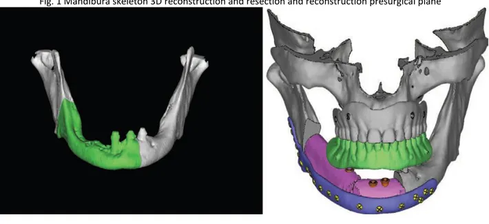
Fig. 1 Mandibura skeleton 3D reconstruction and resection and reconstruction presurgical plane
The planned surgery was used to design and manufacture the customized surgical devices (mandibular cutting guides, fibular cutting guides, and reconstructive plates). The computer-aided design of the surgical device was conducted using Rhino software, version 4.0 (Robert McNeel & Associates, Seattle, Wash.). Computer-Aided Design Procedure The customized mandible cutting guides were designed to precisely reproduce the site and orientation of the osteotomies for tumor ablation from the virtual plan into the surgical environment.
The mandibular guides were designed with points of reference to allow only the planned positioning on the mandible: arms were included to allow the precise engagement of the device on the mandible. Four holes (2.4-mm diameter) were created for fixation of the guides to the mandible with titanium screws, as described by Leiggener et al.9 A fibular osteotomy guide was used.
This allows the free flap to fit the defect perfectly, as planned preoperatively. The third component of the device was the customized reconstructive bone plate that supported the fibula/iliac free flap. The bone plate was designed by thickening the outer surface of the healthy side of the mandible to obtain an ideal aesthetic contour and avoid bone deformities on the side affected by the tumor. Positioning of the reconstructive plate could be guided using this method; the holes created to fix the guide were also used to position the reconstructive plates (“transferring principle”). Computer-Aided Manufacturing and Rapid Prototyping Procedures
The solid-to-layer files of the guide and plate were then manufactured by direct metal laser sintering using an EOSINT M270 system (Electro- Optical Systems, GmbH, Munich, Germany). Direct metal laser sintering was used to fuse the metal powder into a solid form and then melt it locally with a focused laser beam. As with other additive manufacturing technologies, the components were built up additively in layers. The cutting guide, created using Electro-Optical Systems Cobalt-Chrome MP1 (Electro-Optical Systems), was a multipurpose cobalt-chrome-molybdenum– based superalloy powder optimized for direct metal laser sintering on EOSINT M systems. The bone plate was produced using Electro-Optical Systems Titanium Ti64 (Electro-Optical Systems), a prealloyed Ti6AIV4 alloy
in fine-powder form with excellent mechanical properties and corrosion resistance, low specific weight, and good biocompatibility, characteristics that make it particularly suitable for the production of biomedical implants. To provide the surgeons “biomodels” of the mandible in the preoperative condition and after the planned osteotomy, the biomodels were manufactured directly using a three-dimensional soluble support technology rapid prototyping machine (Stratasys, Eden Prairie, Minn.) (Fig. 2).
Fig.2 Cad-Cam Titanium custom made plate
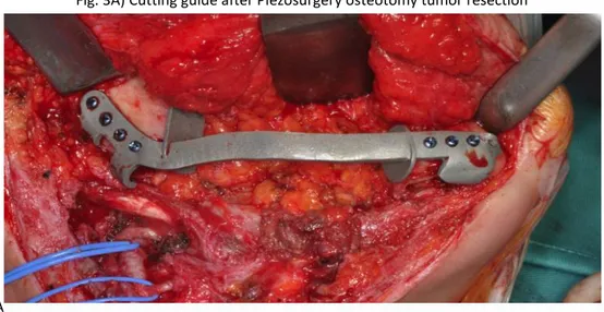
The mandibles were accessed through a sub– transmandibular/cervicolateral incision, and the tumors were delineated. The cutting guide was introduced into the field and fixed to the mandibular bone, leaving the proposed surgical margins within safe tissues. The cutting guides were fixed with titanium screws (Fig. 3A ), and a Piezosurgery device (Mectron, Genova Italy) was then used to perform the osteotomy. The cutting guides were removed after resection of the mandible
Fig. 3A) Cutting guide after Piezosurgery osteotomy tumor resection
A
The reconstructive bone plates were positioned and used to support the fibula/iliac free flaps to restore the original mandibular contour. The bone plate was introduced and fixed to the mandible using the same holes with which the cutting guide had been fixed to ensure correct mutual positioning of the two components (Fig. 3B e C, D).
Fig. 3B) Fibula Cutting guide presurgical planes
3D) Fibula and Cad-Cam Custom made plate reconstruction
Study Design The study included patients affected by mandibular tumors that required mandibular resection and reconstruction using a free fibula flap.
All patients were evaluated by computed tomographic scans obtained preoperatively and 1 month after surgery, using the same machine and identical parameters. All the values were compared with the criterion standard value that was 0 mm/degree of difference with respect to the natural, intended preoperative position of the bone. In those cases in which cancer altered the external lines of the native anatomy, the criterion standard with which to compare the values after surgery was considered the mirrored healthy surface of the contralateral side. For this reason, a positive or negative value was given to all measurements to better describe in what direction the alteration occurred; however, in terms of statistics, only absolute values were considered. Mandibular angle shift landmarks are listed in Table 1 with their original negative/positive values: a negative value was given if the malposition was toward the median line of the skull (x plane/frontal plane); and, with respect to the sagittal plane (lateral y plane), a positive value was given when the mandible angle landmark was shifted toward and negative if shifted back. The patients were divided into test and control groups (Table 2).
To evaluate the accuracy of the prosthetically guided maxillofacial surgery method, the virtual plan was compared with the postoperative computed tomographic scan. The control group included five patients who underwent reconstruction by indirect preplating: the standard osteosynthesis plates were manually bent preoperatively on a stereolithographic model of the mandible
A number of factors indicative of the precision/accuracy of the reconstruction were evaluated on the postoperative computed tomographic scan of each patient. The results achieved in the test group were compared with those of the control group. Accuracy Evaluation The factors indicative of the precision and accuracy of the reconstruction were as follows:
1) themidline deviation on the vertical and horizontal plane,
2) the variation on the horizontal and sagittal planes of the mandibular angle (angle shift),
3) the angular deviation of the mandibular arch as a contracture toward the median axis or as a lateral expansion, and
4) the condyle position (Fig. 4).
The first parameter was calculated at the median line of the inferior border of the mandible; this point was detected on the horizontal and vertical planes to determine its lateral deviation and retrusion, respectively.
The second parameter (the mandibular angle shift) was measured on the horizontal and vertical (sagittal) planes for the left and right ramus.
The third parameter, the angular deviation of the mandibular arch, was a measure of the contracture/reduction of the arch and was intended to measure the preservation of the native mandibular occlusal arch position.
Thecondylar position (fourth parameter) was assessed taking into account the external pole of each condyle, as shown in the image; this was also calculated on the horizontal and vertical planes.
Statistical analysis was conducted using t test, and t values were calculated with 10 degrees of freedom; the threshold was p = 0.05, and the confidence interval for difference was 95 percent.
RESULTS
No significant difference in midline deviation between the control and test groups was identified (Table 3). The mean deviation on the vertical (frontal) plane was 1.713 mm in the test group and 1.061 mm in the control group (p = 0.380); on the horizontal plane, the mean deviation was 0.728 mm in the test group and 3.436 mm in the control group (p = 0.232). However, on the horizontal plane, three patients showed a 0-mm deviation in the test group (60 percent of patients), compared with four cases in the control group (57.1 percent). The mean values of the right mandibular angle shift (Table 1) in the test group were as follows: in the right angle, 1.899 mm on the frontal (x) plane and 2.006 mm on the lateral (y) plane; in the left angle, 1.539 mm on the frontal plane and 1.400 mm on the lateral plane. In the control group, the mean values were 2.451 mm on the frontal (x) plane (p = 0.294) and 1.613 mm on the lateral (y) plane (p = 0.628); the shift of the left mandibular angle was 1.652 mm on the frontal (x) plane (p = 0.824) and 5.042 mm on the lateral (y) plane (p = 0.006). The differences between groups were not statistically significant, with the exception of that between the left angle shift on the lateral (y) plane (p = 0.006). The mean angular deviations of the mandibular body (mandible arch contracture or expansion) (Table 4) in the test group were 0.941 degree in the right body and 2.240 degrees in the left body; in the control group, they were 8.941 degrees in the right body (p = 0.054) and 8.198 degrees in the left body (p = 0.085). The difference between groups in terms of the facial contracture of the external profile at the lower margin of the mandible was near significant value (p = 0.054) for the right, but not for the left (p = 0.085). The mean values of the condyle position (Table 5) in the test group were 0.789 in the left condyle and 1.297 in the right. In the control group, the mean values of the left and right condyles were 2.457 and 4.458, respectively. The difference between groups was significant for the right (p = 0.035), but not for the left (p = 0.068).
DISCUSSION
Computer-aided design/computer-aided manufacturing and rapid prototyping technologies have been introduced in the field of maxillofacial bone reconstruction to increase precision and reduce morbidity and procedure time. The accuracy evaluation of the precision of both surgical techniques, prosthetically guided maxillofacial surgery and the indirect computer-aided design/computer-aided manufacturing procedure, was carried out by comparing preoperative and postoperative computed tomography data using specific anatomical landmarks. These were positioned at the extreme lateral point of the condyles and at the median mental position to evaluate the eventual malposition of the condyle after surgery and the eventual deviation of the mandibular arch (frontal plane rotation). Moreover, an angular measurement of the mandibular arch was taken to assess the contracture or expansion of the mandible. Linear measurement of the mandibular angle shift (toward the front or back) was also performed. These parameters were particularly important for prosthetic rehabilitation because maintenance of the occlusal arch and the position of the mandibular angle are fundamental for generation of appropriate intermaxillary postoperative relationships. Results showed that a highly accurate reproduction was obtained using the prosthetically guided maxillofacial surgery computer-aided design/computer-aided manufacturing procedure, which was in some instances
statistically different from the conventional reconstructive technique (indirect computer-aided design/computer-aided manufacturing). Midline deviation: No significant difference between the test and control groups was documented, including when the difference in the mean value on the y plane (horizontal) was greater. This was because of the possibility of precise shaping of the reconstructive plate using the preplating technique on the rapidly prototyped resin biomodel. The stereolithographic models facilitated more accurate contouring of the bone plate without eventual alteration of the anatomy because of the cancer. Mandibular angle shift: Only one left angle shift on the lateral plane showed a statistically significant difference between the groups. This may be due to the precision of the indirect and prosthetically guided maxillofacial surgery computer-aided design/computeraided manufacturing techniques in terms of mandibular body length. Angular deviation of the body axis: The data showed an important difference in the arch deviation (nearly a statistically significant difference in the right body) (p = 0.054). All patients in the control group exhibited higher
degrees of deviation than those in the test group, determining a facial contracture of the external profile at the lower margin of the mandible. This causes evident aesthetic alteration and variation of the occlusal arch that increases the difficulty associated with oral rehabilitation: the position of the reconstructed bone is either too lateral (lateral defect) or too retruded (anterior defect) with respect to the occlusal plane of the upper jaw, causing transversal arch incoordination. This problem has a marked effect on maxillofacial prosthetic rehabilitation in terms of patient satisfaction and home hygienic care and maintenance. Condylar position: The postoperative condylar position yielded better control in the test group versus the control group. The difference was statistically significant for only the left condyle, likely because six of seven patients in the test group and four of five patients in the control group underwent surgical procedures on the left side. These data confirm that the deviation is more significant in condyles of the operated side when prosthetically guided maxillofacial surgery is not used. This important result influenced the functional activity of the condyle. However, except two mean values (midline x plane and right angle y plane), all mean values of the test group were lower than those of the control group, evidencing an improvement of
the accuracy when using prosthetically guided maxillofacial surgery. The surgical protocol presented in this article offers also several clinical advantages. These were analyzed qualitatively but not quantitatively on the basis of the surgeon’s experience. The first advantage is that the virtual environment permitted ideal preoperative planning for tumor ablation: the boundaries of the resection were placed accurately in safe tissues. The cutting guide allowed the site and orientation of the planned osteotomies to be replicated accurately during surgery. The second advantage is that intraoperative time was not consumed by approximately and repeatedly modeling the plate to the native mandible (as in conventional procedures that do not use stereolithographic models). This
technique reduced surgical time by approximately 2 hours (corresponding to approximately €1.340) because of the rapidity of fibula insetting and the elimination of preplating. Moreover, the cost of
the commercial bone plate (corresponding to approximately €700) was avoided, because of the direct rapid prototyping of the bone plate. Finally, no complications occurred postoperatively. The
reconstruction plate provided an appropriate bone-plate relationship and maintained correct occlusal centric relation. Condylar distortion and poor functional outcome were avoided. The patients regained good masticatory performance 3 weeks after surgery. Potential drawbacks of this technique include difficulties in adapting to situations in which the surgical plane changes intraoperatively (i.e., positive margins), and the cost of designing and prototyping the device. To avoid positive margins during surgery, the times between computed tomographic scan examination, the beginning
of the computer-aided design/computer-aided manufacturing procedure, and surgery should be minimized to not more than 2 weeks. Further investigations are necessary to compare the tolerance and mechanical properties of custom-made titanium reconstruction plates with those of the commercially available plates that are currently used in reconstructive surgery
CONCLUSIONS
Seven consecutive patients underwent mandibular reconstruction by means of a novel method involving computer-aided design/computer- computer-aided manufacturing prosthetically guided maxillofacial surgery to produce a custom-made surgical guide and reconstructive plate. The virtual planning of a guide for mandibular segment repositioning/osteotomies and a reconstructive plate manufactured using direct metal laser sintering technology facilitated restoration of mandibular function and native mandibular contour when using microvascular free flaps. This method also provides the surgeon better procedural control and reduces procedure time, and the prosthodontist is provided with an anatomy suitable for restoration using implant-supported oral prostheses.
1. Marchetti C, Bianchi A, Mazzoni S, Cipriani R, Campobassi A. Oromandibular reconstruction using a fibula osteocutaneous free flap: Four different “preplating” techniques. Plast Reconstr Surg. 2006;118:643–651.
2. Scolozzi P, Momjian A, Heuberger J. Computer-aided volumetric comparison of reconstructed orbits for blow-out fractures with nonpreformed versus 3-dimensionally preformed titanium mesh plates: A preliminary study. J Comput Assist Tomogr. 2010;34:98– 104.
3. Chen XY, Chen SL, Zhang X, Li JP, Deng W. Accuracy of intraoral vertical ramus osteotomy with a stereolithographic template. Ann Plast Surg. 2011;66:88–91.
4. Ibrahim D, Broilo TL, Heitz C, et al. Dimensional error of selective laser sintering, three-dimensional printing and PolyJet models in the reproduction of mandibular anatomy. J Craniomaxillofac Surg. 2009;37:167–173.
5. Weitz J, Deppe H, Stopp S, Lueth T, Mueller S, Hohlweg- Majert B. Accuracy of templates for navigated implantation made by rapid prototyping with DICOM datasets of cone beam computer tomography (CBCT). Clin Oral Investig. 2011;15:1001–1006. 6. Ciocca L, Mazzoni S, Fantini M, Persiani F, Baldissara P, Marchetti C, Scotti R. A CAD/CAM-prototyped anatomical condylar prosthesis connected to a custom-made bone plate to support a fibula free flap. Med Biol Eng Comput. 2012;50:743–749.
7. Ciocca L, Mazzoni S, Fantini M, Marchetti C, Scotti R. The design and rapid prototyping of surgical guides and bone plates to support iliac free flaps for mandible reconstruction. Plast Reconstr Surg. 2012;129:859e–861e.
8. Ciocca L, Mazzoni S, Fantini M, Persiani F, Marchetti C, Scotti R. CAD/CAM guided secondary mandibular reconstruction of a discontinuity defect after ablative cancer surgery. J Craniomaxillofac Surg. 2012;40:e511–e515.
9. Leiggener C, Messo E, Thor A, Zeilhofer HF, Hirsch JM. A selective laser sintering guide for transferring a virtual plan to real time surgery in composite mandibular reconstruction with free fibula osseous flaps. Int J Oral Maxillofac Surg. 2009;38:187–192.
3c) Extractive Surgery
Introduction
Third molar surgery is one of the most common procedures performed by oral and maxillofacial surgeons (1). Extraction of the mandibular third molar may range from relatively easy to extremely difficult depending on its location, depth, angulation, and the density of the bone (2). One of the most critical phases during extraction is the osteotomy, for which many techniques are used, and if they are performed improperly, they can be dangerous (3). Piezosurgery is a relatively new osteotomy technique using micro vibrations of scalpels at ultrasonic frequencies to perform safe and effective osteotomies. Piezoelectric surgery is effective in osteotomies because it works selectively, being largely inert against soft tissues, including nerves and blood vessels, a significant advantage compared with a bur (4). When used appropriately, Piezosurgery causes less damage at the structural and cellular levels compared with other techniques. Also, new bone formation is more rapid than with rotating burs (5).
Several previous studies have demonstrated that the micrometric cutting action of Piezosurgery requires a longer surgery time compared with bur use, potentially causing more discomfort in the postoperative period(6), (7), (8). The study purpose was to evaluate piezosurgery devices versus a conventional osteotomy for the removal of lower third molars; the investigators hypothesize that surgical technique using piezosurgery devices was overall less invasive than traditional surgical techniques using drills mounted on a handpiece at high or low speed. The primary endpoint of the study were to evaluate: surgical time, pain, trismus, and swelling. Secondary endpoint was evaluate Patient’s clinical quality of life using Postoperative Symptom Severity scale.
The aim of this study was to evaluate Piezosurgery devices versus a conventional osteotomy for the removal of lower third molars, evaluating whether the surgical technique using Piezosurgery devices was overall less invasive than traditional surgical techniques using drills mounted on a handpiece at high or low speed.
Patients and Methods
This study followed the Declaration of Helsinki on medical protocol and ethics. The Ethical Review Board of S. Orsola-Malpighi Hospital, AOU, approved the study.
Ten consecutive patients who required removal of both impacted lower third molars were recruited. Using a flip coin decision, we alternately remove both molars using a conventional rotating handpiece or a Piezosurgery unit (Mectron Piezosurgery, Medical Technology, Carasco, GE, Italy). At least 30 days passed between the two extractions.
Inclusion criteria were molars that required muco-periostal flap and osteoplasty, teeth of the same difficulty score on both sides, according to the Yuasa Scale (9), and age in the range 18-25 years. Exclusion criteria were teeth affected by acute infections, such as pericoronitis, an acute alveolar abscess, or oral submucous fibrosis at the time of the operation.
All patients were informed about the procedures, postoperative recovery times, and possible complications, and signed a detailed consent form. After we had taken a full medical and dental history, at a minimum orthopantomograms (OPGs) were taken, and treatment began.
Surgical Technique
Prophylactic therapy was given to all patients: amoxicillin with clavulanic acid 2 g, 1 h before the operation. All operations were performed under local anesthesia, using mepivacaine with 1:100,000 adrenaline bitartrate. In both groups, a conventional Ward’s incision was made to reflect the flap, then a mucoperiosteal flap was raised with a periosteal (Molt’s No. 9) elevator to expose the impacted tooth and surrounding bone. Osteoplasty was performed on the buccal and lingual sides. On the test side, the Piezosurgery (Mectron Piezosurgery) surgical kit (OT5, OT7, OT1) was used. On the control side, a carbide round bur in a straight handpiece at 35,000 rpm was used. On both sides, odontotomy, when needed, was completed using a tungsten carbide fissure bur in a no-air-spray high-speed handpiece, taking care to avoid contact with the bone.
At all times, cutting of bone and teeth was accompanied by copious irrigation with chilled saline solution. After the tooth had been removed, the extraction socket was debrided and closed with 4/0 absorbable, synthetic, braided sutures. The duration of the operation was noted in each case. Postoperatively, patients were instructed to take amoxicillin with clavulanic acid 1 g at 8 h after the surgery and 0.5 g, four times daily for 4 days, and analgesic therapy as needed.
A) Piezosurgery Osteoplasty B) Macrovibration drill Osteolasty
A B
C) Coronectomy
C
D) Piezosurgery Roots separation E) Macrovibration Drill Roots separation
Evaluation
Pain, trismus, and swelling were evaluated at baseline and 7 days post-operatively. Post-operative pain was assessed with a visual analog scale (VAS) of 10 units and a graphic rating scale (10). The number of analgesic tablets taken was also recorded. Trismus was evaluated by measuring the interincisal distance (cm) at maximum mouth opening with a ruler (11). Swelling was measured according to Schultze-Mosgau (12) using digital calipers from the lingual aspect of the crown of the first mandibular molar to the tangent of the skin of the cheek (13).
A questionnaire, the Postoperative Symptom Severity (PoSSe) scale, was given to each patient after surgery. These questions are commonly used in the clinical assessment of patients who have had third molars extracted. The scale consists of seven subscales that include the patient’s ability to enjoy food, speak properly, perceive altered sensations, and their appearance, pain, sickness, and interference with daily activities. (14)
Data were entered into a spreadsheet (Excel; Microsoft, Inc., Redmond, WA) over the course of the study. Descriptive statistics were computed for all study variables using the SPSS software (ver. 12.0 for Windows; SPSS Inc., Chicago, IL). F, G) Swelling and Trismus Evaluation
F G
E) VAS scale fro pain evaluation
Results
Ten consecutive patients were included in the study. All had both asymptomatic impacted mandibular third molars. Their mean age (SD) was 22.4 (2.3) years. In each patient, both of the teeth had the same difficulty index, according to the Yuasa Scale. In particular, the teeth had the same scores for depth, ramus relationship, and width of roots. Using a randomized, flip coin list we divided the two third molars in each patient into the test group (Piezosurgery extraction) and the control group (conventional rotating handpiece). The mean (SD) surgery time in the test group was 36.8 (10.6) min, while in the control group, it was 30.8 (6.1) min (P = 0.115). Postoperative swelling occurred in both groups. We measured it before surgery and 7 days post-operatively using digital calipers. At 1 week after surgery, the mean (SD) swelling in the test group was 2.75 cm (0.23 cm), lower than in the control group, 3.1 cm (0.39 cm) (P = 0.027).
Patients were asked to take post-operative analgesic therapy as needed. There was no difference in total analgesic tablet numbers in the groups (test: 48; mean per day 0.6, versus control: 47; mean per day 0.6) . A VAS of 10 units was completed by the patients every day for 6 days post-operatively. There was no difference between the groups (Fig 2). Trismus was evaluated every day post-operatively, by measuring the interincisal distance (cm) at maximum mouth opening with a ruler. Except at day 2, no difference was identified between the groups. (Fig 3).
To understand patient feelings, we used a health-related quality-of-life questionnaire, the PoSSe scale. The full-scale results were better in the test group: mean value (SD) 24.7% (10.3%) versus the control group, 33.1% (9.3%) (P = 0.036). The speech, appearance, and interference with daily activity subscale scores were also better in the test group than in the control group.(Tab 1, Fig 1)